

Page 1

Firepower MST 220i
3-IN-1 Multi Process
Welding Systems
Operating
Manual
www.Firepower.com
English
Canadien Français
Americas Español
Revision: AA Issue Date: May 13, 2014 Manual No.: 0-5343
Page 2

WE APPRECIATE YOUR BUSINESS!
Congratulations on receiving your new Firepower product. We are proud to have you as our customer
and will strive to provide you with the best service and support in the industry. This product is backed
by our extensive warranty and world-wide service network.
We know you take pride in your work and we feel privileged to provide you with this high performance
product that will help you get the job done.
YOU ARE IN GOOD COMPANY!
Firepower is a Global Brand of Arc Welding Products for Victor Technologies Inc. We distinguish
ourselves from our competition through market-leading innovation and truly dependable products that
will stand the test of time.
We strive to enhance your productivity, efficiency and welding performance enabling you to excel in
your craft. We design products with the welder in mind delivering- advanced features, durability, ease
of use and ergonomic comfort.
Above all, we are committed to a safer working environment within the welding industry. Your
satisfaction with this product and its safe operation is our ultimate concern. Please take the time to
read the entire manual, especially the Safety Precautions.
If you have any questions or concerns regarding your new Firepower product, please contact our
friendly and knowledgeable Customer Service Team at:
1-800-462-2782 (USA) and 1-905-827-4515 (Canada),
or visit us on the web at www.Firepower.com
Page 3

!
WARNINGS
Read and understand this entire Manual and your employer’s safety practices before installing,
operating, or servicing the equipment.
While the information contained in this Manual represents the Manufacturer’s best judgment,
the Manufacturer assumes no liability for its use.
Operating Manual Number 0-5343 for:
Firepower MST 220i Portable system Package Part Number: 1444-0872
Published by:
Victor Technologies, Inc.
16052 Swingley Ridge Road,
Suite 300 St. Louis, MO 63017
USA
www.Firepower.com
Copyright © 2014 by
Victor Technologies, Inc.
® All rights reserved.
Reproduction of this work, in whole or in part, without written permission of the
publisher is prohibited.
The publisher does not assume and hereby disclaims any liability to any party for any
loss or damage caused by any error or omission in this Manual, whether such error
results from negligence, accident, or any other cause.
Publication Date: May 13, 2014
Revision Date:
Record the following information for Warranty purposes:
Where Purchased: ____________________________________
Purchase Date: ____________________________________
Equipment Serial #: ____________________________________
Page 4

TABLE OF CONTENTS
SECTION 1: SAFETY INSTRUCTIONS AND WARNINGS ............................................... 1-1
1.01 Arc Welding Hazards ....................................................................................... 1-1
1.02 General Safety Information For Victor CS Regulator ......................................... 1-5
1.03 Principal Safety Standards .............................................................................. 1-7
1.04 Symbol Chart .................................................................................................. 1-8
1.05 Precautions De Securite En Soudage A L’arc .................................................. 1-9
1.06 Dangers relatifs au soudage à l’arc ................................................................. 1-9
1.07 Informations Générales de Sécurité .............................................................. 1-14
1.08 Principales Normes De Securite ................................................................... 1-16
1.09 Graphique de Symbole .................................................................................. 1-17
SECTION 2: INTRODUCTION ............................................................................. 2-1
2.01 How To Use This Manual ................................................................................ 2-1
2.02 Equipment Identification ................................................................................. 2-1
2.03 Receipt Of Equipment ..................................................................................... 2-1
2.04 Description ..................................................................................................... 2-1
2.05 Transportation Methods .................................................................................. 2-2
2.06 User Responsibility ......................................................................................... 2-2
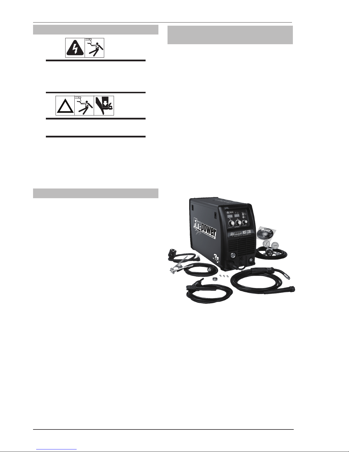
2.07 Firepower MST 220i Portable System Package (Part No. 1444-0872) ............ 2-2
2.08 Duty Cycle ....................................................................................................... 2-3
2.09 Specifications ................................................................................................. 2-4
2.10 Optional Accessories ...................................................................................... 2-5
2.11 Volt-Ampere Curves ........................................................................................ 2-6
SECTION 3: INSTALLATION, OPERATION AND SETUP ................................................ 3-1
3.01 Environment ................................................................................................... 3-1
3.02 Location .......................................................................................................... 3-1
3.03 Ventilation ....................................................................................................... 3-1
3.04 Electricity Supply ........................................................................................... 3-1
3.05 Electromagnetic Compatibility ........................................................................ 3-4
3.06 Firepower Regulator ....................................................................................... 3-5
3.07 Leak Testing The System ................................................................................ 3-8
3.08 When You Finish Using The Regulator ............................................................ 3-8
3.09 Storage Of The Regulator ............................................................................... 3-8
3.10 Firepower MST 220i Power Source Controls, Indicators And Features ........... 3-9
3.11 Attaching the Firepower Fusion 220A MIG Gun ............................................ 3-16
3.12 Installing 33/44 lb Spool (12" diameter) ...................................................... 3-17
3.13 Installing 12.5 lb Spool ( 8" diameter) .......................................................... 3-18
3.14 Installing 1 lb Spool (4" diameter) ................................................................ 3-19
3.15 Inserting Wire Into The Wire Feed Mechanism ............................................. 3-20
3.16 Feed Roller Pressure Adjustment .................................................................. 3-21
3.17 Changing the Feed Roll ................................................................................. 3-21
3.18 Wire Reel Brake ............................................................................................ 3-22
3.19 Setup For MIG (GMAW) Welding With Gas Shielded MIG Wire .................... 3-22
3.20 Setup For MIG (FCAW) Welding With Flux Core (Gasless) Wire ................... 3-24
3.21 Setup For SPOOL GUN MIG (GMAW) Welding With Gas Shielded MIG Wire 3-25
3.22 Setup For LIFT TIG (GTAW) Welding ............................................................. 3-26
3.23 Setup For STICK (SMAW) Welding .............................................................. 3-28
Page 5

TABLE OF CONTENTS
SECTION 4:
BASIC WELDING GUIDE ............................................................................. 4-1
4.01 MIG (GMAW/FCAW) Basic Welding Technique ............................................... 4-1
4.02 MIG (GMAW/FCAW) Welding Troubleshooting ............................................... 4-5
4.03 STICK (SMAW) Basic Welding Technique ....................................................... 4-8
4.04 Effects of Arc Welding Various Materials ........................................................ 4-8
4.05 STICK (SMAW) Welding Troubleshooting ..................................................... 4-16
4.06 TIG (GTAW) Basic Welding Technique .......................................................... 4-18
4.07 TIG (GTAW) Welding Problems ..................................................................... 4-20
SECTION 5: POWER SOURCE PROBLEMS AND ROUTINE SERVICE REQUIREMENTS ............ 5-1
5.01 Power Source Problems ................................................................................. 5-1
5.02 Routine Service and Calibration Requirements ............................................... 5-2
5.03 Cleaning the Welding Power Source ............................................................... 5-5
5.04 Cleaning the Feed Rolls ................................................................................... 5-6
SECTION 6: KEY SPARE PARTS .......................................................................... 6-1
6.01 Firepower Fusion 220A MIG Gun .................................................................... 6-1
6.02 Power Source Spare Parts .............................................................................. 6-2
APPENDIX 1: FIREPOWER MST 220i CIRCUIT DIAGRAM ............................................ A-1
FIREPOWER - LIMITED WARRANTY TERMS ......................................INSIDE REAR COVER
GLOBAL CUSTOMER SERVICE CONTACT INFORMATION ................................. REAR COVER
Page 6

This Page Intentionally Blank
Page 7
FIREPOWER MST 220i
Manual 0-5343 1-1 SAFETY INSTRUCTIONS AND WARNINGS
1.01 Arc Welding Hazards
WARNING
ELECTRIC SHOCK can kill.
Touching live electrical parts can cause
fatal shocks or severe burns. The electrode
and work circuit is electrically live when
ever the output is on. The input power circuit and machine internal circuits are also
live when power is on. In semi-automatic
or automatic wire welding, the wire, wire
reel, drive roll housing, and all metal parts
touching the welding wire are electrically
live. Incorrectly installed or improperly
grounded equipment is a hazard.
1. Do not touch live electrical parts.
2. Wear dry, hole-free insulating gloves and body
protection.
3. Insulate yourself from work and ground using dry
insulating mats or covers.
4. Disconnect input power or stop engine before
installing or servicing this equipment. Lock input
power disconnect switch open, or remove line
fuses so power cannot be turned ON accidentally.
5. Properly install and ground this equipment
according to its Owner’s Manual and national,
state, and local codes.
6. Turn OFF all equipment when not in use.
Disconnect power to equipment if it will be left
unattended or out of service.
7. Use fully insulated electrode holders. Never dip
holder in water to cool it or lay it down on the
ground or the work surface. Do not touch holders
connected to two welding machines at the same
time or touch other people with the holder or
electrode.
8. Do not use worn, damaged, undersized, or poorly
spliced cables.
9. Do not wrap cables around your body.
10. Ground the workpiece to a good electrical (earth)
ground.
11. Do not touch electrode while in contact with the
work (ground) circuit.
12. Use only well-maintained equipment. Repair or
replace damaged parts at once.
13. In confined spaces or damp locations, do not use
a welder with AC output unless it is equipped with
a voltage reducer. Use equipment with DC output.
14. Wear a safety harness to prevent falling if working
above floor level.
15. Keep all panels and covers securely in place.
SECTION 1: SAFETY INSTRUCTIONS AND WARNINGS
!
WARNING
PROTECT YOURSELF AND OTHERS FROM POSSIBLE SERIOUS INJURY OR DEATH. KEEP CHILDREN
AWAY. PACEMAKER WEARERS KEEP AWAY UNTIL CONSULTING YOUR DOCTOR. DO NOT LOSE THESE
INSTRUCTIONS. READ OPERATING/INSTRUCTION MANUAL BEFORE INSTALLING, OPERATING OR
SERVICING THIS EQUIPMENT.
Welding products and welding processes can cause serious injury or death, or damage to other equipment or
property, if the operator does not strictly observe all safety rules and take precautionary actions.
Safe practices have developed from past experience in the use of welding and cutting. These practices must be
learned through study and training before using this equipment. Some of these practices apply to equipment
connected to power lines; other practices apply to engine driven equipment. Anyone not having extensive
training in welding and cutting practices should not attempt to weld.
Safe practices are outlined in the American National Standard Z49.1 entitled: SAFETY IN WELDING AND
CUTTING. This publication and other guides to what you should learn before operating this equipment are
listed at the end of these safety precautions. HAVE ALL INSTALLATION, OPERATION, MAINTENANCE, AND
REPAIR WORK PERFORMED ONLY BY QUALIFIED PEOPLE.
Page 8
FIREPOWER MST 220i
SAFETY INSTRUCTIONS AND WARNINGS 1-2 Manual 0-5343
WARNING
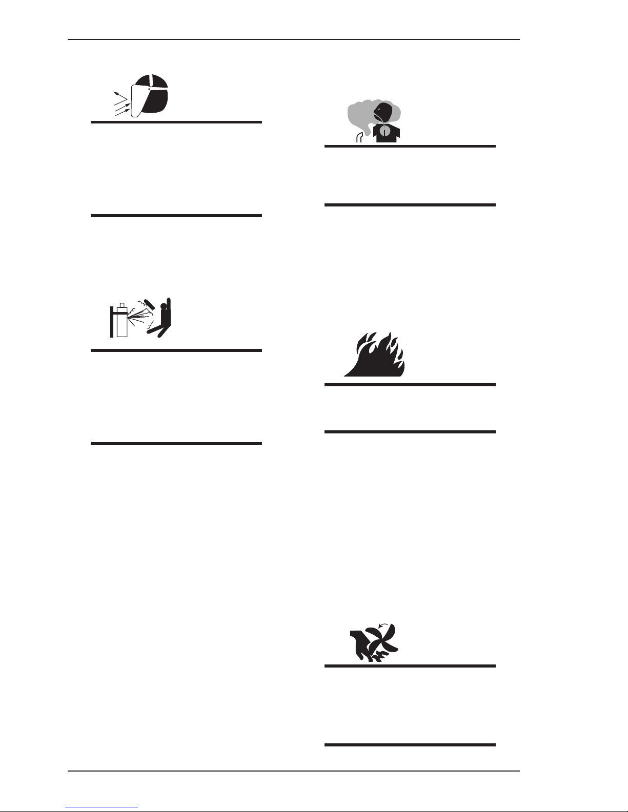
ARC RAYS can burn eyes and skin; NOISE
can damage hearing. Arc rays from the
welding process produce intense heat and
strong ultraviolet rays that can burn eyes
and skin. Noise from some processes can
damage hearing.
1. Wear a welding helmet fitted with a proper shade
of filter (see ANSI Z49.1 listed in Safety Standards)
to protect your face and eyes when welding or
watching.
2. Wear approved safety glasses. Side shields
recommended.
3. Use protective screens or barriers to protect others
from flash and glare; warn others not to watch the
arc.
4. Wear protective clothing made from durable,
flame-resistant material (wool and leather) and
foot protection.
5. Use approved ear plugs or ear muffs if noise level
is high.
WARNING
FUMES AND GASES can be hazardous to
your health.
Welding produces fumes and gases.
Breathing these fumes and gases can be
hazardous to your health.
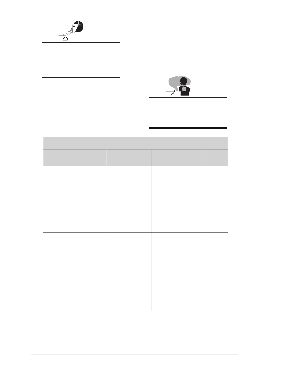
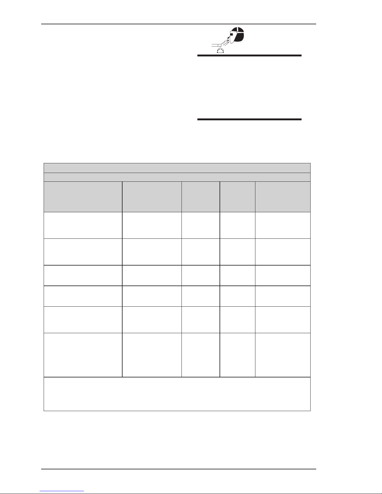
AWS F2.2:2001 (R2010), Adapted with permission of the American Welding Society (AWS), Miami, Florida
Guide for Shade Numbers
Process
Electrode Size in.
(mm)
Arc Current
(Amperes)
Minimum
Protective
Shade
Suggested*
Shade No.
(Comfort)
Shielded Metal Arc Welding
(SMAW)
Less than 3/32 (2.4)
3/32-5/32 (2.4-4.0)
5/32-1/4 (4.0-6.4)
More than 1/4 (6.4)
Less than 60
60-160
160-250
250-550
7
8
10
11
10
12
14
Gas Metal Arc Welding (GMAW)
and Flux Cored Arc Welding
(FCAW)
Less than 60
60-160
160-250
250-550
7
10
10
10
11
12
14
Gas Tungsten arc Welding
(GTAW)
Less than 50
50-150
150-500
8
8
10
10
12
14
Air Carbon Arc Cutting (CAC-A)
(Light)
(Heavy)
Less than
500
500-1000
10
11
12
14
Plasma Arc Welding (PAW)
Less than 20
20-100
100-400
400-800
6
8
10
11
6 to 8
10
12
14
Plasma Arc Cutting (PAC)
Less than 20
20-40
40-60
60-80
80-300
300-400
400-800
4
5
6
8
8
9
10
4
5
6
8
9
12
14
* As a rule of thumb, start with a shade that is too dark to see the weld zone. Then go to a lighter shade
which gives sufficient view of the weld zone without going below the minimum. In oxyfuel gas welding,
cutting, or brazing where the torch and/or the flux produces a high yellow light, it is desirable to use a
filter lens that absorbs the yellow or sodium line of the visible light spectrum.
Page 9
FIREPOWER MST 220i
Manual 0-5343 1-3 SAFETY INSTRUCTIONS AND WARNINGS
1. Keep your head out of the fumes. Do not breathe
the fumes.
2. If inside, ventilate the area and/or use exhaust at
the arc to remove welding fumes and gases.
3. If ventilation is poor, use an approved air-supplied
respirator.
4. Read the Material Safety Data Sheets (MSDSs)
and the manufacturer’s instruction for metals,
consumables, coatings, and cleaners.
5. Work in a confined space only if it is well ventilated,
or while wearing an air-supplied respirator.
Shielding gases used for welding can displace air
causing injury or death. Be sure the breathing air
is safe.
6. Do not weld in locations near degreasing, cleaning,
or spraying operations. The heat and rays of the
arc can react with vapors to form highly toxic and
irritating gases.
7. Do not weld on coated metals, such as galvanized,
lead, or cadmium plated steel, unless the coating
is removed from the weld area, the area is well
ventilated, and if necessary, while wearing an airsupplied respirator. The coatings and any metals
containing these elements can give off toxic fumes
if welded.
WARNING
WELDING can cause fire or explosion.
Sparks and spatter fly off from the
welding arc. The flying sparks and hot
metal, weld spatter, hot workpiece, and
hot equipment can cause fires and burns.
Accidental contact of electrode or welding
wire to metal objects can cause sparks,
overheating, or fire.
1. Protect yourself and others from flying sparks and
hot metal.
2. Do not weld where flying sparks can strike
flammable material.
3. Remove all flammables within 35 ft (10.7 m) of the
welding arc. If this is not possible, tightly cover
them with approved covers.
4. Be alert that welding sparks and hot materials from
welding can easily go through small cracks and
openings to adjacent areas.
5. Watch for fire, and keep a fire extinguisher nearby.
6. Be aware that welding on a ceiling, floor, bulkhead,
or partition can cause fire on the hidden side.
7. Do not weld on closed containers such as tanks
or drums.
8. Connect work cable to the work as close to the
welding area as practical to prevent welding
current from travelling long, possibly unknown
paths and causing electric shock and fire hazards.
9. Do not use welder to thaw frozen pipes.
10. Remove stick electrode from holder or cut off
welding wire at contact tip when not in use.
WARNING
FLYING SPARKS AND HOT METAL can
cause injury.
Chipping and grinding cause flying metal.
As welds cool, they can throw off slag.
1. Wear approved face shield or safety goggles. Side
shields recommended.
2. Wear proper body protection to protect skin.
WARNING
CYLINDERS can explode if damaged.
Shielding gas cylinders contain gas under
high pressure. If damaged, a cylinder can
explode. Since gas cylinders are normally
part of the welding process, be sure to
treat them carefully.
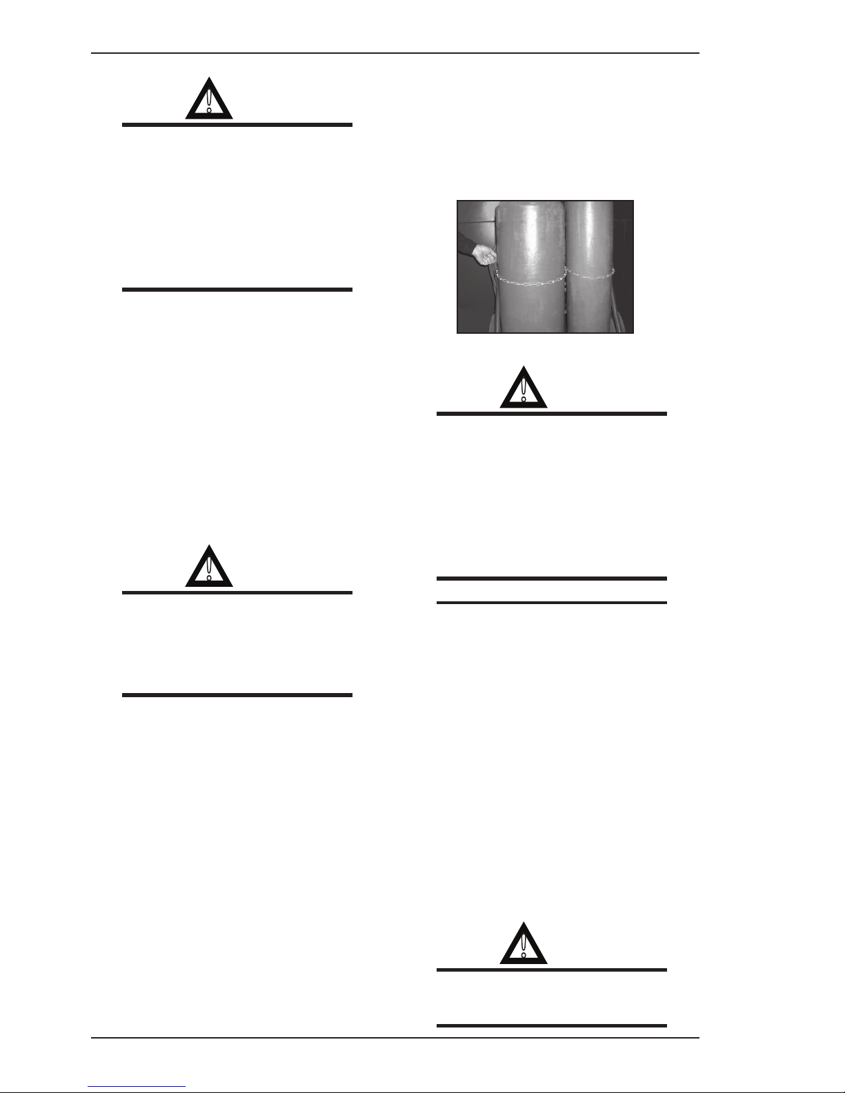
1. Protect compressed gas cylinders from excessive
heat, mechanical shocks, and arcs.
2. Install and secure cylinders in an upright position
by chaining them to a stationary support or
equipment cylinder rack to prevent falling or
tipping.
3. Keep cylinders away from any welding or other
electrical circuits.
4. Never allow a welding electrode to touch any
cylinder.
5. Use only correct shielding gas cylinders,
regulators, hoses, and fittings designed for the
specific application; maintain them and associated
parts in good condition.
6. Turn face away from valve outlet when opening
cylinder valve.
7. Keep protective cap in place over valve except
when cylinder is in use or connected for use.
Page 10

FIREPOWER MST 220i
SAFETY INSTRUCTIONS AND WARNINGS 1-4 Manual 0-5343
8. Read and follow instructions on compressed
gas cylinders, associated equipment, and CGA
publication P-1 listed in Safety Standards.
!
WARNING
Engines can be dangerous.
WARNING
ENGINE EXHAUST GASES can kill.
Engines produce harmful exhaust gases.
1. Use equipment outside in open, well-ventilated
areas.
2. If used in a closed area, vent engine exhaust
outside and away from any building air intakes.
WARNING
ENGINE FUEL can cause fire or explosion.
Engine fuel is highly flammable.
1. Stop engine before checking or adding fuel.
2. Do not add fuel while smoking or if unit is near
any sparks or open flames.
3. Allow engine to cool before fuelling. If possible,
check and add fuel to cold engine before beginning
job.
4. Do not overfill tank — allow room for fuel to
expand.
5. Do not spill fuel. If fuel is spilled, clean up before
starting engine.
WARNING
MOVING PARTS can cause injury.
Moving parts, such as fans, rotors, and belts can cut
fingers and hands and catch loose clothing.
1. Keep all doors, panels, covers, and guards
closed and securely in place.
2. Stop engine before installing or connecting
unit.
3. Have only qualified people remove guards or
covers for maintenance and troubleshooting
as necessary.
4. To prevent accidental starting during servicing,
disconnect negative (-) battery cable from
battery.
5. Keep hands, hair, loose clothing, and tools
away from moving parts.
6. Reinstall panels or guards and close doors
when servicing is finished and before starting
engine.
WARNING
SPARKS can cause BATTERY GASES TO
EXPLODE; BATTERY ACID can burn eyes
and skin.
Batteries contain acid and generate explosive gases.
1. Always wear a face shield when working on a
battery.
2. Stop engine before disconnecting or connecting
battery cables.
3. Do not allow tools to cause sparks when working
on a battery.
4. Do not use welder to charge batteries or jump start
vehicles.
5. Observe correct polarity (+ and –) on batteries.
WARNING
STEAM AND PRESSURIZED HOT
COOLANT can burn face, eyes, and skin.
The coolant in the radiator can be very hot
and under pressure.
1. Do not remove radiator cap when engine is hot.
Allow engine to cool.
2. Wear gloves and put a rag over cap area when
removing cap.
3. Allow pressure to escape before completely
removing cap.
!
WARNING
WARNING: This product contains chemicals, includ-
ing lead, known to the State of California to cause
birth defects and other reproductive harm.
Wash
hands after handling.
Page 11
FIREPOWER MST 220i
Manual 0-5343 1-5 SAFETY INSTRUCTIONS AND WARNINGS
NOTE
Considerations About Welding And The
Effects of Low Frequency Electric and
Magnetic Fields
The following is a quotation from the General Conclusions Section of the U.S. Congress, Office of
Technology Assessment, Biological Effects of Power
Frequency Electric & Magnetic Fields - Background
Paper, OTA-BP-E-63 (Washington, DC: U.S. Government Printing Office, May 1989): “...there is now
a very large volume of scientific findings based on
experiments at the cellular level and from studies with
animals and people which clearly establish that low
frequency magnetic fields interact with, and produce
changes in, biological systems. While most of this
work is of very high quality, the results are complex.
Current scientific understanding does not yet allow us
to interpret the evidence in a single coherent framework. Even more frustrating, it does not yet allow
us to draw definite conclusions about questions of
possible risk or to offer clear science-based advice
on strategies to minimize or avoid potential risks.”
To reduce magnetic fields in the workplace, use the
following procedures.
1. Keep cables close together by twisting or
taping them.
2. Arrange cables to one side and away from the
operator.
3. Do not coil or drape cable around the body.
4. Keep welding Power Source and cables as far
away from body as practical.
ABOUT PACEMAKERS:
The above procedures are among
those also normally recommended for
pacemaker wearers. Consult your doctor
for complete information.
1.02 General Safety Information For
Victor CS Regulator
A Fire Prevention
Welding and cutting operations use fire or combustion as a basic tool. The process is very useful when
properly controlled. However, it can be extremely
destructive if not performed cor rectly in the proper
environment.
1. The work area must have a fireproof floor.
2. Work benches or tables used during welding
or cutting operations must have fireproof
tops.
3. Use heat resistant shields or other approved
material to protect nearby walls or unprotected
flooring from sparks and hot metal.
4. Keep an approved fire extinguisher of the
proper size and type in the work area. Inspect
it regularly to ensure that it is in proper working order. Know how to use the fire extinguisher.
5. Move combustible materials away from the
work site. If you can not move them, protect
them with fireproof covers.
!
WARNING
NEVER perform welding, heating, or cutting operations on a container that has
held toxic, combustible or flammable liquids, or vapors. NEVER perform welding,
heating, or cutting operations in an area
containing combustible vapors, flam mable
liquids, or explosive dust.
B Housekeeping
!
WARNING
NEVER allow oxygen to contact grease, oil,
or other flam mable substances. Although
oxygen by itself will not burn, these sub
stances become highly explosive. They
can ignite and burn violently in the pres
ence of oxygen.
Keep ALL apparatus clean and free of grease, oil and
other flammable substances.
Page 12
FIREPOWER MST 220i
SAFETY INSTRUCTIONS AND WARNINGS 1-6 Manual 0-5343
C Ventilation
!
WARNING
Ade quately ventilate welding, heating, and
cutting work areas to prevent accumula
tion of explosive or toxic concen trations
of gases. Certain combinations of metals,
coatings, and gases generate toxic fumes.
Use respiratory protection equipment
in these circumstances. When welding/
brazing, read and understand the Mate
rial Safety Data Sheet for the welding/
brazing alloy.
D Personal Protection
Gas flames produce infrared radiation which may
have a harm ful effect on the skin and especially on the
eyes. Select goggles or a mask with tempered lenses,
shaded 4 or darker, to protect your eyes from injury
and provide good visibility of the work.
Always wear protective gloves and flame-resistant clothing to protect skin and clothing from sparks and slag.
Keep collars, sleeves, and pockets buttoned. DO NOT
roll up sleeves or cuff pants.
When working in a non-welding or cutting environment, always wear suitable eye protection or face
shield.
!
WARNING
Practice the following safety and operation
precautions EVERY TIME you use pressure
regulation equipment. Deviation from the
following safety and operation instructions
can result in fire, explosion, damage to
equipment, or injury to the operator.
E Compressed Gas Cylinders
The Department of Transportation (DOT) approves
the design and manufacture of cylinders that contain
gases used for welding or cutting operations.
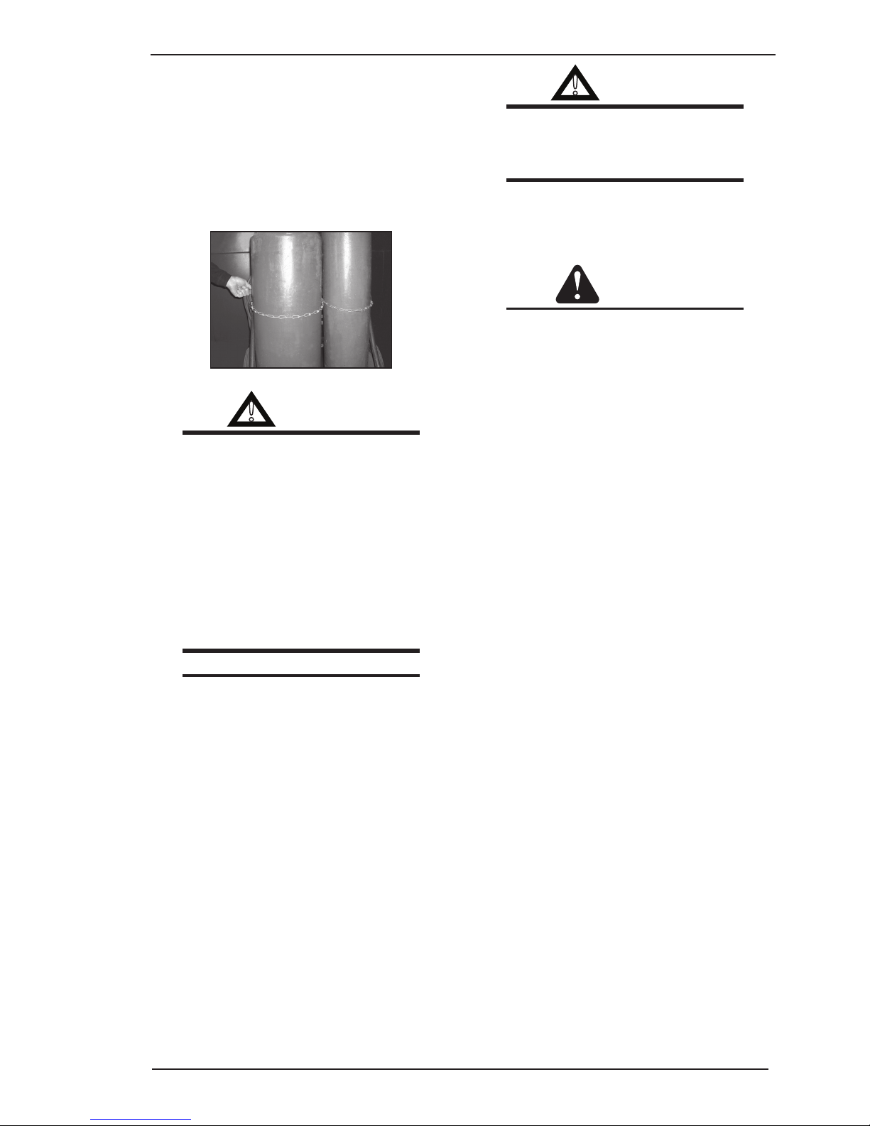
1. Place the cylinder (Figure 1-1) where you will
use it. Keep the cylinder in a vertical position.
Secure it to a cart, wall, work bench, post, etc.
Art # A-12127
Figure 1-1: Gas Cylinders
!
WARNING
Cylinders are highly pressurized. Handle
with care. Serious accidents can result
from improper handling or mis use of
compressed gas cylinders DO NOT drop
the cylinder, knock it over, or expose it to
excessive heat, flames or sparks. DO NOT
strike it against other cylinders. Contact
your gas supplier or refer to CGA P-1
“Safe Handling of Compressed Gases in
Containers” publication.
NOTE
CGA P-1 publication is available by writing the Compressed Gas Association,
4221 Walney Road, 5th Floor, Chantilly,VA
20151-2923
2. Place the valve protection cap on the cylinder
whenever mov ing it, placing it in storage, or not
using it. Never drag or roll cylinders in any way.
Use a suitable hand truck to move cylin ders.
3. Store empty cylinders away from full cylinders.
Mark them “EMPTY” and close the cylinder
valve.
4. NEVER use compressed gas cylinders without
a pressure reducing regulator attached to the
cylinder valve.
5. Inspect the cylinder valve for oil, grease, and
damaged parts.
!
WARNING
DO NOT use the cylinder if you find oil,
grease or damaged parts. Inform your
gas supplier of this condition immediately.
Page 13

FIREPOWER MST 220i
Manual 0-5343 1-7 SAFETY INSTRUCTIONS AND WARNINGS
6. Momentarily open and close (called “cracking”)
the cylinder valve to dislodge any dust or dirt
that may be present in the valve.
CAUTION
Open the cylinder valve slightly. If you
open the valve too much, the cylinder
could tip over. When cracking the cylinder
valve, DO NOT stand directly in front of the
cylinder valve. Always perform cracking
in a well ventilated area. If an acetylene
cylinder sprays a mist when cracked, let
it stand for 15 minutes. Then, try to crack
the cylinder valve again. If this problem
persists, contact your gas supplier.
1.03 Principal Safety Standards
Safety in Welding and Cutting, ANSI Standard Z49.1,
from American Welding Society, 550 N.W. LeJeune
Rd., Miami, FL 33126.
Safety and Health Standards, OSHA 29 CFR 1910,
from Superintendent of Documents, U.S. Government
Printing Office, Washington, D.C. 20402.
Recommended Safe Practices for the Preparation for
Welding and Cutting of Containers That Have Held
Hazardous Substances, American Welding Society
Standard AWS F4.1, from American Welding Society,
550 N.W. LeJeune Rd., Miami, FL 33126.
National Electrical Code, NFPA Standard 70, from
National Fire Protection Association, Batterymarch
Park, Quincy, MA 02269.
Safe Handling of Compressed Gases in Cylinders, CGA
Pamphlet P-1, from Compressed Gas Association,
1235 Jefferson Davis Highway, Suite 501, Arlington,
VA 22202.
Code for Safety in Welding and Cutting, CSA Standard
W117.2, from Canadian Standards Association,
Standards Sales, 178 Rexdale Boulevard, Rexdale,
Ontario, Canada M9W 1R3.
Safe Practices for Occupation and Educational Eye and
Face Protection, ANSI Standard Z87.1, from American
National Standards Institute, 1430 Broadway, New
York, NY 10018.
Cutting and Welding Processes, NFPA Standard
51B, from National Fire Protection Association,
Batterymarch Park, Quincy, MA 02269.
Page 14
FIREPOWER MST 220i
SAFETY INSTRUCTIONS AND WARNINGS 1-8 Manual 0-5343
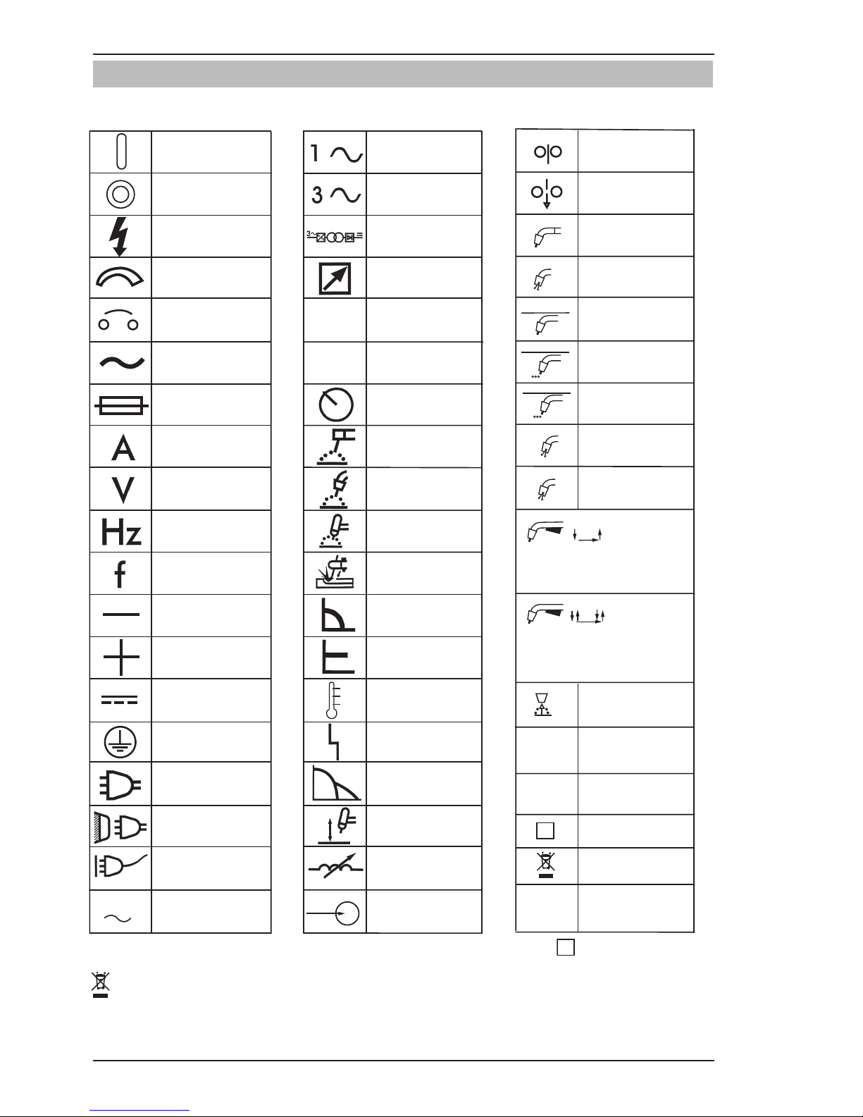
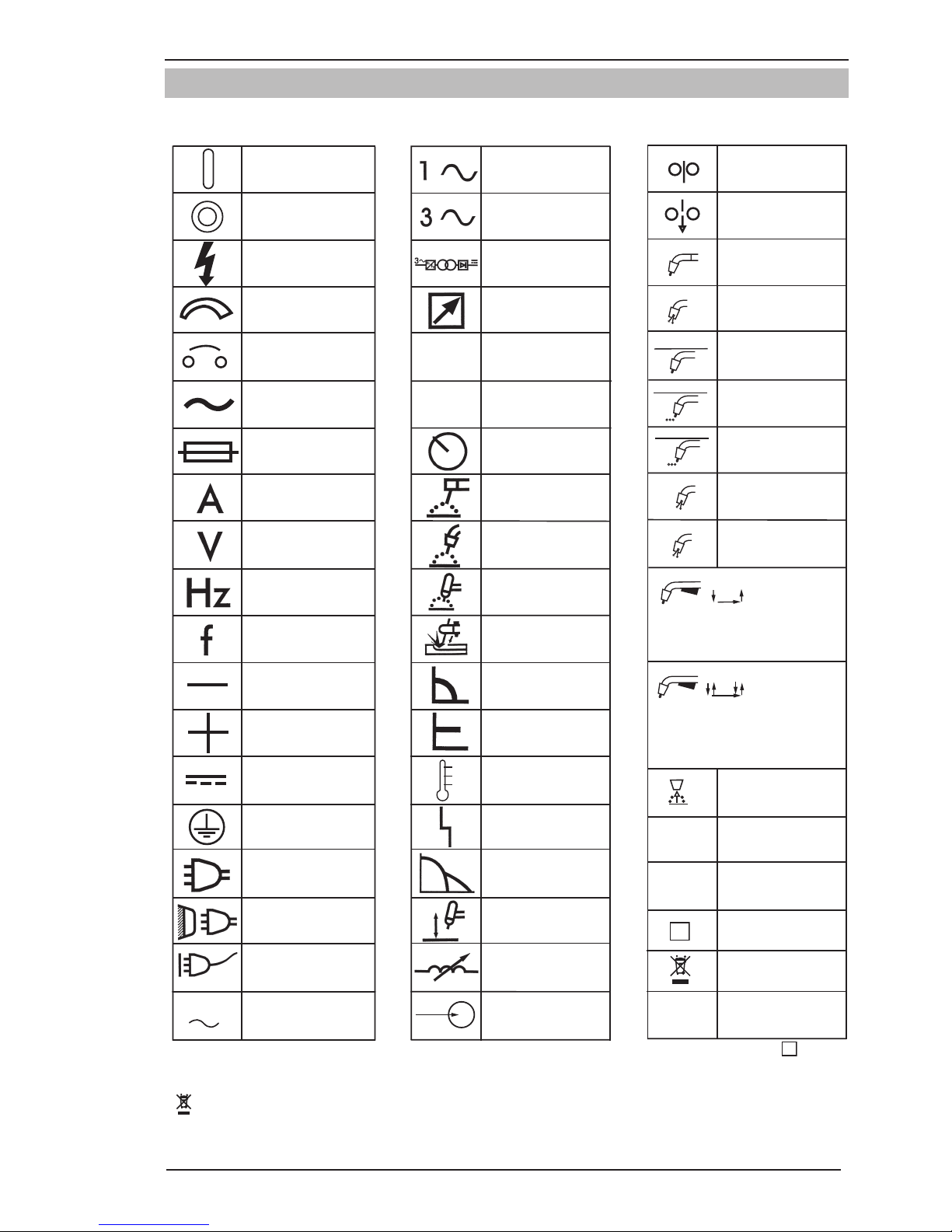
1.04 Symbol Chart
Note that only some of these symbols will appear on your model.
Gas Tungsten Arc
Welding (GTAW)
Air Carbon Arc
Cutting (CAC-A)
Constant Current
Constant Voltage
Or Constant Potential
High Temperature
Fault Indication
Arc Force
Touch Start (GTAW)
Variable Inductance
Voltage Input
Single Phase
Three Phase
Three Phase Static
Frequency ConverterTransformer-Rectifier
Dangerous Voltage
Off
On
Panel/Local
Shielded Metal
Arc Welding (SMAW)
Gas Metal Arc
Welding (GMAW)
Increase/Decrease
Circuit Breaker
AC Auxiliary Power
Remote
Duty Cycle
Percentage
Amperage
Voltage
Hertz (cycles/sec)
Frequency
Negative
Positive
Direct Current (DC)
Protective Earth
(Ground)
Line
Line Connection
Auxiliary Power
Receptacle RatingAuxiliary Power
Art # A-04130_AB
115V 15A
t
t1
t2
%
X
IPM
MPM
t
V
Fuse
Wire Feed Function
Wire Feed Towards
Workpiece With
Output Voltage Off.
Preflow Time
Postflow Time
Spot Time
Spot Weld Mode
Continuous Weld
Mode
Press to initiate wirefeed and
welding, release to stop.
Purging Of Gas
Inches Per Minute
Meters Per Minute
Welding Gun
Burnback Time
Press and hold for preflow, release
to start arc. Press to stop arc, and
hold for preflow.
4 Step Trigger
Operation
2 Step Trigger
Operation
S
See Note
See Note
S
Note: For environments with increased hazard of electrical shock, Power Supplier bearing the mark conform to EN50192
when used in conjunction with hand torches with exposed tips, if equipped with properly installed standoff guides.
Cannot be disposed with household garbage.
Page 15

FIREPOWER MST 220i
Manual 0-5343 1-9 SAFETY INSTRUCTIONS AND WARNINGS
1.05 Precautions De Securite En Soudage A L’arc
!
MISE EN GARDE
LE SOUDAGE A L’ARC EST DANGEREUX
PROTEGEZ-VOUS, AINSI QUE LES AUTRES, CONTRE LES BLESSURES GRAVES POSSIBLES OU LA MORT.
NE LAISSEZ PAS LES ENFANTS S’APPROCHER, NI LES PORTEURS DE STIMULATEUR CARDIAQUE (A
MOINS QU’ILS N’AIENT CONSULTE UN MEDECIN). CONSERVEZ CES INSTRUCTIONS. LISEZ LE MANUEL
D’OPERATION OU LES INSTRUCTIONS AVANT D’INSTALLER, UTILISER OU ENTRETENIR CET EQUIPEMENT.
Les produits et procédés de soudage peuvent sauser des blessures graves ou la mort, de même que des
dommages au reste du matériel et à la propriété, si l’utilisateur n’adhère pas strictement à toutes les règles
de sécurité et ne prend pas les précautions nécessaires.
En soudage et coupage, des pratiques sécuritaires se sont développées suite à l’expérience passée. Ces pratiques doivent être apprises par étude ou entraînement avant d’utiliser l’equipement. Toute personne n’ayant
pas suivi un entraînement intensif en soudage et coupage ne devrait pas tenter de souder. Certaines pratiques
concernent les équipements raccordés aux lignes d’alimentation alors que d’autres s’adressent aux groupes
électrogènes.
La norme Z49.1 de l’American National Standard, intitulée “SAFETY IN WELDING AND CUTTING” présente
les pratiques sécuritaires à suivre. Ce document ainsi que d’autres guides que vous devriez connaître avant
d’utiliser cet équipement sont présentés à la fin de ces instructions de sécurité.
SEULES DES PERSONNES QUALIFIEES DOIVENT FAIRE DES TRAVAUX D’INSTALLATION, DE REPARATION,
D’ENTRETIEN ET D’ESSAI.
1.06 Dangers relatifs au soudage à
l’arc
AVERTISSEMENT
L’ELECTROCUTION PEUT ETRE MORTELLE.
Une décharge électrique peut tuer ou
brûler gravement. L’électrode et le circuit
de soudage sont sous tension dès la mise
en circuit. Le circuit d’alimentation et les
circuits internes de l’équipement sont
aussi sous tension dès la mise en marche.
En soudage automatique ou semi-automa
tique avec fil, ce dernier, le rouleau ou la
bobine de fil, le logement des galets d’en
trainement et toutes les pièces métalliques
en contact avec le fil de soudage sont sous
tension. Un équipement inadéquatement
installé ou inadéquatement mis à la terre
est dangereux.
1. Ne touchez pas à des pièces sous tension.
2. Portez des gants et des vêtements isolants, secs
et non troués.
3 Isolez-vous de la pièce à souder et de la mise à la
terre au moyen de tapis isolants ou autres.
4. Déconnectez la prise d’alimentation de l’équipement ou arrêtez le moteur avant de l’installer ou
d’en faire l’entretien. Bloquez le commutateur en
circuit ouvert ou enlevez les fusibles de l’alimentation afin d’éviter une mise en marche accidentelle.
5. Veuillez à installer cet équipement et à le mettre à
la terre selon le manuel d’utilisation et les codes
nationaux, provinciaux et locaux applicables.
6. Arrêtez tout équipement après usage. Coupez
l’alimentation de l’équipement s’il est hors d’usage
ou inutilisé.
7. N’utilisez que des porte-électrodes bien isolés.
Ne jamais plonger les porte-électrodes dans l’eau
pour les refroidir. Ne jamais les laisser traîner par
terre ou sur les pièces à souder. Ne touchez pas
aux porte-électrodes raccordés à deux sources
de courant en même temps. Ne jamais toucher
quelqu’un d’autre avec l’électrode ou le porteélectrode.
8. N’utilisez pas de câbles électriques usés, endommagés, mal épissés ou de section trop petite.
9. N’enroulez pas de câbles électriques autour de
votre corps.
10. N’utilisez qu’une bonne prise de masse pour la
mise à la terre de la pièce à souder.
11. Ne touchez pas à l’électrode lorsqu’en contact avec
le circuit de soudage (terre).
Page 16
FIREPOWER MST 220i
SAFETY INSTRUCTIONS AND WARNINGS 1-10 Manual 0-5343
12. N’utilisez que des équipements en bon état. Réparez ou remplacez aussitôt les pièces endommagées.
13. Dans des espaces confinés ou mouillés, n’utilisez
pas de source de courant alternatif, à moins qu’il
soit muni d’un réducteur de tension. Utilisez plutôt
une source de courant continu.
14. Portez un harnais de sécurité si vous travaillez en
hauteur.
15. Fermez solidement tous les panneaux et les
capots.
AVERTISSEMENT
LE RAYONNEMENT DE L’ARC PEUT BRÛLER LES YEUX ET LA PEAU; LE BRUIT
PEUT ENDOMMAGER L’OUIE.
L’arc de soudage produit une chaleur et
des rayons ultraviolets intenses, suscep
tibles de brûler les yeux et la peau. Le
bruit causé par certains procédés peut
endommager l’ouïe.
1. Portez une casque de soudeur avec filtre oculaire
de nuance appropriée (consultez la norme ANSI
Z49 indiquée ci-après) pour vous protéger le
visage et les yeux lorsque vous soudez ou que
vous observez l’exécution d’une soudure.
AWS F2.2 : 2001 (R2010), Modifié avec l’accord de l’American Welding Society (AWS), Miami, Florida
Guide de teinte des lentilles
Procédé
Taille de l’électrode
enmm (po)
Courant
d’arc
(ampères)
Gamme
d’intensité
minimum
Numéro de teinte
recommandée*
(Confort)
Soudage à l’arc avec
électrode enrobée (procédé
SMAW)
Moins de 2,4 (3/32)
3/32-5/32 (2,4-4,0)
5/32-1/4 (4,0-6,4)
Plus de 1/4 (6,4)
Moins de 60
60-160
160-250
250-550
7
8
10
11
10
12
14
Soudage à l’arc sous gaz
avec fil plein (procédé
GMAW) et soudage avec fil
fourré (procédé FCAW)
Moins de 60
60-160
160-250
250-550
7
10
10
10
11
12
14
Soudage à l’électrode
réfractaire (procédé GTAW)
Moins de 50
50-150
150-500
8
8
10
10
12
14
Coupage à l’arc avec
électrode de carbone et jet
d’air (procédé AAC)
(Clair)
(Sombre)
Moins de
500 500-
1000
10
11
12
14
Soudage à l’arc au plasma
(procédé PAW)
Moins de 20
20-100
100-400
400-800
6
8
10
11
6 à 8
10
12
14
Coupage plasma (procédé
PAC)
Moins de 20
20-40
40-60
60-80
80-300
300-400
400-800
4
5
6
8
8
9
10
4
5
6
8
9
12
14
* En règle générale, commencer avec une teinte plus foncée pour voir la zone de soudage. Réduire ensuite
progressivement vers la teinte qui permet de voir la zone de soudage sans dépasser le minimum. Lors
dusoudage, du coupage ou du brasage au gaz oxygéné, la torche ou le fondant produit une puissante
lumière jaune; il est préférable d’utiliser un filtre qui absorbe cette lumière jaune ou le sodium du spectre
de la lumière visible.
Tableau 1-1
Page 17

FIREPOWER MST 220i
Manual 0-5343 1-11 SAFETY INSTRUCTIONS AND WARNINGS
AVERTISSEMENT
LE SOUDAGE PEUT CAUSER UN INCENDIE OU UNE EXPLOSION
L’arc produit des étincellies et des pro
jections. Les particules volantes, le
métal chaud, les projections de soudure
et l’équipement surchauffé peuvent causer
un incendie et des brûlures. Le contact
accidentel de l’électrode ou du fil-électrode
avec un objet métallique peut provoquer
des étincelles, un échauffement ou un
incendie.
1. Protégez-vous, ainsi que les autres, contre les
étincelles et du métal chaud.
2. Ne soudez pas dans un endroit où des particules
volantes ou des projections peuvent atteindre des
matériaux inflammables.
3. Enlevez toutes matières inflammables dans un
rayon de 10, 7 mètres autour de l’arc, ou couvrezles soigneusement avec des bâches approuvées.
4. Méfiez-vous des projections brulantes de soudage
susceptibles de pénétrer dans des aires adjacentes
par de petites ouvertures ou fissures.
5. Méfiez-vous des incendies et gardez un extincteur
à portée de la main.
6. N’oubliez pas qu’une soudure réalisée sur un
plafond, un plancher, une cloison ou une paroi
peut enflammer l’autre côté.
7. Ne soudez pas un récipient fermé, tel un réservoir
ou un baril.
8. Connectez le câble de soudage le plus près
possible de la zone de soudage pour empêcher
le courant de suivre un long parcours inconnu,
et prévenir ainsi les risques d’électrocution et
d’incendie.
9. Ne dégelez pas les tuyaux avec un source de
courant.
10. Otez l’électrode du porte-électrode ou coupez le fil
au tube-contact lorsqu’inutilisé après le soudage.
11. Portez des vêtements protecteurs non huileux,
tels des gants en cuir, une chemise épaisse, un
2. Portez des lunettes de sécurité approuvées. Des
écrans latéraux sont recommandés.
3. Entourez l’aire de soudage de rideaux ou de cloisons pour protéger les autres des coups d’arc ou
de l’éblouissement; avertissez les observateurs de
ne pas regarder l’arc.
4. Portez des vêtements en matériaux ignifuges
et durables (laine et cuir) et des chaussures de
sécurité.
5. Portez un casque antibruit ou des bouchons
d’oreille approuvés lorsque le niveau de bruit est
élevé.
AVERTISSEMENT
LES VAPEURS ET LES FUMEES SONT
DANGEREUSES POUR LA SANTE.
Le soudage dégage des vapeurs et des
fumées dangereuses à respirer.
1. Eloignez la tête des fumées pour éviter de les
respirer.
2. A l’intérieur, assurez-vous que l’aire de soudage
est bien ventilée ou que les fumées et les vapeurs
sont aspirées à l’arc.
3. Si la ventilation est inadequate, portez un respirateur à adduction d’air approuvé.
4. Lisez les fiches signalétiques et les consignes
du fabricant relatives aux métaux, aux produits
consummables, aux revêtements et aux produits
nettoyants.
5. Ne travaillez dans un espace confiné que s’il
est bien ventilé; sinon, portez un respirateur à
adduction d’air. Les gaz protecteurs de soudage
peuvent déplacer l’oxygène de l’air et ainsi causer
des malaises ou la mort. Assurez-vous que l’air
est propre à la respiration.
6. Ne soudez pas à proximité d’opérations de dégraissage, de nettoyage ou de pulvérisation. La chaleur
et les rayons de l’arc peuvent réagir avec des
vapeurs et former des gaz hautement toxiques et
irritants.
7. Ne soudez des tôles galvanisées ou plaquées au
plomb ou au cadmium que si les zones à souder
ont été grattées à fond, que si l’espace est bien
ventilé; si nécessaire portez un respirateur à
adduction d’air. Car ces revêtements et tout métal
qui contient ces éléments peuvent dégager des
fumées toxiques au moment du soudage.
Page 18
FIREPOWER MST 220i
SAFETY INSTRUCTIONS AND WARNINGS 1-12 Manual 0-5343
pantalon revers, des bottines de sécurité et un
casque.
AVERTISSEMENT
LES ETINCELLES ET LES PROJECTIONS
BRULANTES PEUVENT CAUSER DES
BLESSURES.
Le piquage et le meulage produisent
des particules métalliques volantes. En
refroidissant, la soudure peut projeter du
éclats de laitier.
1. Portez un écran facial ou des lunettes protectrices approuvées. Des écrans latéraux sont
recommandés.
2. Portez des vêtements appropriés pour protéger la peau.
AVERTISSEMENT
LES BOUTEILLES ENDOMMAGEES PEUVENT EXPLOSER
Les bouteilles contiennent des gaz protec
teurs sous haute pression. Des bouteilles
endommagées peuvent exploser. Comme
les bouteilles font normalement partie du
procédé de soudage, traitez-les avec soin.
1. Protégez les bouteilles de gaz comprimé contre
les sources de chaleur intense, les chocs et les
arcs de soudage.
2. Enchainez verticalement les bouteilles à un support
ou à un cadre fixe pour les empêcher de tomber
ou d’être renversées.
3. Eloignez les bouteilles de tout circuit électrique ou
de tout soudage.
4. Empêchez tout contact entre une bouteille et une
électrode de soudage.
5. N’utilisez que des bouteilles de gaz protecteur,
des détendeurs, des boyauxs et des raccords
conçus pour chaque application spécifique; ces
équipements et les pièces connexes doivent être
maintenus en bon état.
6. Ne placez pas le visage face à l’ouverture du robinet de la bouteille lors de son ouverture.
7. Laissez en place le chapeau de bouteille sauf si en
utilisation ou lorsque raccordé pour utilisation.
8. Lisez et respectez les consignes relatives aux
bouteilles de gaz comprimé et aux équipements
connexes, ainsi que la publication P-1 de la CGA,
identifiée dans la liste de documents ci-dessous.
AVERTISSEMENT
LES MOTEURS PEUVENT ETRE DANGEREUX
LES GAZ D’ECHAPPEMENT DES MO
-
TEURS PEUVENT ETRE MORTELS.
Les moteurs produisent des gaz d’échappement
nocifs.
1. Utilisez l’équipement à l’extérieur dans des aires
ouvertes et bien ventilées.
2. Si vous utilisez ces équipements dans un endroit
confiné, les fumées d’échappement doivent être
envoyées à l’extérieur, loin des prises d’air du
bâtiment.
AVERTISSEMENT
LE CARBURANT PEUR CAUSER UN
INCENDIE OU UNE EXPLOSION.
Le carburant est hautement inflammable.
1. Arrêtez le moteur avant de vérifier le niveau e
carburant ou de faire le plein.
2. Ne faites pas le plein en fumant ou proche d’une
source d’étincelles ou d’une flamme nue.
3. Si c’est possible, laissez le moteur refroidir avant
de faire le plein de carburant ou d’en vérifier le
niveau au début du soudage.
4. Ne faites pas le plein de carburant à ras bord:
prévoyez de l’espace pour son expansion.
5. Faites attention de ne pas renverser de carburant.
Nettoyez tout carburant renversé avant de faire
démarrer le moteur.
AVERTISSEMENT
DES PIECES EN MOUVEMENT PEUVENT
CAUSER DES BLESSURES.
Des pièces en mouvement, tels des ven
tilateurs, des rotors et des courroies peuvent couper doigts et mains, ou accrocher
des vêtements amples.
Page 19
FIREPOWER MST 220i
Manual 0-5343 1-13 SAFETY INSTRUCTIONS AND WARNINGS
1. Assurez-vous que les portes, les panneaux, les
capots et les protecteurs soient bien fermés.
2. Avant d’installer ou de connecter un système,
arrêtez le moteur.
3. Seules des personnes qualifiées doivent démonter
des protecteurs ou des capots pour faire l’entretien
ou le dépannage nécessaire.
4. Pour empêcher un démarrage accidentel pendant
l’entretien, débranchez le câble d’accumulateur à
la borne négative.
5. N’approchez pas les mains ou les cheveux de pièces en mouvement; elles peuvent aussi accrocher
des vêtements amples et des outils.
6. Réinstallez les capots ou les protecteurs et fermez
les portes après des travaux d’entretien et avant
de faire démarrer le moteur.
AVERTISSEMENT
DES ETINCELLES PEUVENT FAIRE EXPLOSER UN ACCUMULATEUR; L’ELECTROLYTE D’UN ACCUMU-LATEUR PEUT
BRULER LA PEAU ET LES YEUX.
Les accumulateurs contiennent de l’élec
trolyte acide et dégagent des vapeurs
explosives.
1. Portez toujours un écran facial en travaillant sur
un accumu-lateur.
2. Arrêtez le moteur avant de connecter ou de déconnecter des câbles d’accumulateur.
3. N’utilisez que des outils anti-étincelles pour travailler sur un accumulateur.
4. N’utilisez pas une source de courant de soudage pour charger un accumulateur ou survolter
momentanément un véhicule.
5. Utilisez la polarité correcte (+ et –) de l’accumulateur.
AVERTISSEMENT
LA VAPEUR ET LE LIQUIDE DE REFROIDISSEMENT BRULANT SOUS PRESSION
PEUVENT BRULER LA PEAU ET LES
YEUX.
Le liquide de refroidissement d’un radia
-
teur peut être brûlant et sous pression.
1. N’ôtez pas le bouchon de radiateur tant que le
moteur n’est pas refroidi.
2. Mettez des gants et posez un torchon sur le bouchon pour l’ôter.
3. Laissez la pression s’échapper avant d’ôter complètement le bouchon.
!
AVERTISSEMENT
AVERTISSEMENT: Ce produitcontient des produits
chimiques, notamment du plomb, reconnu par
l’Étatde la Californie pour causerdes malformations congénitaleset d’autresdommages touchant
le système reproductif.
Se laver les mains après
manipulation.
REMARQUE
Facteurs relatifs au soudage et aux effets
des champs magnétiques et électriques
de basse fréquence
Voici une citation tirée du chapitre des conclusions
générales du document de base de l’Office of
Technology Assessment (bureau des évaluations
technologiques) del’U.S. Congress, « Biological
Effects of Power Frequency Electric & Magnetic Fields
», OTA-BP-E-63 (Washington, DC : U.S. Government
Printing Office, mai 1989) : « ... il existe de nos
jours, un nombre très élevé de travaux scientifiques
qui rapportent les résultats d’expériences menées
au niveau cellulaire et d’études auprès d’homme et
d’animaux qui établissent nettement le rapport entre
les champs magnétiques de basse fréquence et les
systèmes biologiques, soit par des interactions ou des
modifications. Quoique la plupart de ces travaux soient
de très bonne qualité, les résultats sont complexes.
Àla lumière des connaissances scientifiques actuelles,
il nous est encore impossible d’interpréter les évidences
en un seul cadre de référence cohérent. La situation est
toutefois très contrariante. En effet, il nous est aussi
impossible de tirer des conclusions définitives quant
aux risques éventuels ou de proposer des stratégies
fondées sur des faits scientifiques visant à atténuer ou
éviter des risques potentiels ».
Pour atténuer les champs magnétiques sur les lieux
detravail, respectez les procédures qui suivent :
1. Maintenez les câbles l’un près de l’autre en les
entrelaçant ou les reliant ensemble au ruban.
2. Acheminez les câbles à un côté du soudeur,
le plus loin possible.
3. N’enroulez pas de câble autour du corps.
4. Maintenez le bloc d’alimentation du poste
desoudage et les câbles aussi loin que
possible du corps.
Page 20
FIREPOWER MST 220i
SAFETY INSTRUCTIONS AND WARNINGS 1-14 Manual 0-5343
STIMULATEURS CARDIAQUES :
Les procédures décrites ci-dessus sont
habituellement celles recommandées pour
les porteurs de stimulateurs cardiaques.
Pour de plus amples renseignements,
consulter unmédecin.
1.07 Informations Générales de
Sécurité
A Prévention D’incendie
Les opérations de soudage utilisent le feu ou la combustion comme outil de base. Ce processus est très utile
quand il est cor rectement contrôlé.
1. La zone doit comporter un sol ignifugé.
2. Les établis ou tables utilisés pendant les
opérations de soudage doivent avoir un
revêtement ignifuge.
3. Utilisez des écrans résistants à la chaleur
ou en matériau approuvé pour protéger les
cloisons proches ou le sol vul nérable des
étincelles et du métal chaud.
4. Gardez un extincteur approuvé du bon type et de
la bonne taille dans la zone de travail. Inspectez-le
régulièrement pour vous assurer qu’il est en état
de fonctionner. Apprenez à vous en servir.
5. Enlevez tous les matériaux combustibles de la
zone de travail. Si vous ne pouvez pas les enlever,
protégez-les avec une cou vre ignifuge.
!
AVERTISSEMENT
N’effectuez JAMAIS d’opérations de soudage sur un récipient qui a contenu des
liquides ou vapeurs toxiques, combusti
bles ou inflammables. N’effectuez JAMAIS
d’opérations de soudage dans une zone
contenant des vapeurs combustibles, des
liquides inflammables ou des poussières
explosives.
B Entretien des Locaux
!
AVERTISSEMENT
Ne laissez jamais l’oxygène en contact
avec la graisse, l’huile ou d’autres subs
tances inflammables. Bien que l’oxygène
elle même ne brûle pas, ces substances
peuvent devenir extrême ment explosives.
Elles peuvent prendre feu et brûler violemment en présence d’oxygène.
Gardez TOUS les appareils propres et exempts de
graisse, huile ou autres substances inflammables.
C Aération
!
AVERTISSEMENT
Ventilez les zones de soudage, chauffage
et découpage de façon adéquate pour
éviter l’accumulation de gaz explosifs
ou toxiques. Certaines combinaisons de
métaux, revêtements et gaz génèrent des
fumées toxiques: Utilisez un équipement
de protection respiratoire dans ces cir
constances. Si vous soudez ou brasez,
lisez et assimilez la fiche technique de
sécurité de matériau relative à l’alliage de
soudage/brasage.
D Protection Personnelle
Les flammes de gaz produisent une radiation infrarouge qui peut avoir un effet néfaste sur la peau, et
particulièrement sur les yeux. Choisissez des lunettes
ou un masque avec des verres trempés assombris au
niveau 4 ou plus sombre, pour protéger vos yeux des
dommages et garder une bonne visibilité sur le travail.
Portez en permanence des gants de protection et des
vête ments ignifuges pour la protection de la peau
et des vêtements contre les étincelles et le laitier.
Gardez col, manches et poches boutonnés. Il ne faut
pas remonter vos manches ou les pantalons à revers.
Quand vous travaillez dans un environnement non
dédié au soudage ou découpage, portez toujours une
protection des yeux appropriées ou un masque facial.
!
AVERTISSEMENT
Mettez en pratique les procédures de sécurité et de mode opératoire suivantes à
chaque fois que vous utilisez cet appareil
de régulation de pression. Si vous déviez
de ces procédures, cela peut entraîner
incendie, explosion, dégâts matériels et/
ou blessures corporelles pour l’opérateur.
Page 21
FIREPOWER MST 220i
Manual 0-5343 1-15 SAFETY INSTRUCTIONS AND WARNINGS
E Bouteilles de Gaz Comprimé
Le Département des Transports américain (DOT)
approuve la conception et la fabrication des bouteilles
qui contiennent les gaz utilisés pour les opérations de
soudage ou de découpage.
1. Placez la bouteille (Le schéma 1) là où elle sera
utilisée. Gardez-la en position verticale. Fixez-la sur
un chariot une cloison, un établi, etc.
Art # A-12127
Le schéma 1-1: Cylindres de gaz
!
AVERTISSEMENT
Les bouteilles sont sous haute pression.
Manipulez-les avec précautions. Des accidents
sérieux peuvent résulter d’une mauvaise manu
tention ou d’un mauvais emploi des bouteilles de
gaz comprimé. NE faites PAS tomber la bouteille,
ne la cognez pas, ne l’exposez pas à une chaleur
excessive, aux flammes ou étincelles. NE la
cognez PAS contre d’autres bouteilles. Contactez
votre fournisseur de gaz ou reportez vous à la
publication CGA P-1 “Manipulation sécurisée
des gaz comprimés en conteneur” pour plus
d’informations sur l’utilisation et la manutention
des bouteilles.
AVIS
Ce document CGA p. t peut être obtenu
en écrivant à “Compressed Gas Asso
ciation”, 4221 Walney Roed, 5th Floor.
Chantilly, VA 20151.2923, USA.
2. Placez le bouchon de protection de vanne sur
la bouteille à chaque fois que vous la déplacez
ou ne l’utilisez pas. Ne faites jamais glisser ou
rouler d’aucune manière les bouteilles. Utilisez
un diable approprié pour les déplacer.
3. Entreposez les bouteilles vides à l’écart des
bouteilles pleines. Marquez-les “VIDE” et
refermez leur vanne.
4. N’utilisez JAMAIS des bouteilles de gaz comprimé sans un régulateur de pression en série
sur la vanne de bouteille.
5. Inspectez la vanne de bouteille pour y détecter de l’huile ou de la graisse, ou dès pièces
endommagées.
!
AVERTISSEMENT
N’UTILISEZ PAS la bouteille si vous trouvez de l’huile, de la graisse ou des pièces
endommagées. Informez immédiate ment
votre fournisseur de’ gaz de cet état.
6. Ouvrez et fermez momentanément la vanne
de la bouteille, délogeant ainsi d’éventu lIes
poussières ou saletés. qui pour raient être
présentes dans la vanne.
MISE EN GARDE
Ouvrez la vanne de bouteille légèrement.
Si vous l’ouvrez trop en grand, la bouteille
pourrait se renverser. Quand vous ouvrez/
fermez rapidement la vanne de bouteille,
ne vous tenez pas directement devant.
Opérez toujours cette opération dans une
zone bien ventilée. Si une bouteille d’acé
tylène crache un brouillard, laissez reposer
pendant 15 minutes. Essayez de nouveau
la vanne. Si le problème persiste, con tactez
votre fournisseur de gaz.
Page 22

FIREPOWER MST 220i
SAFETY INSTRUCTIONS AND WARNINGS 1-16 Manual 0-5343
1.08 Principales Normes De Securite
Safety in Welding and Cutting, norme ANSI Z49.1,
American Welding Society, 550 N.W. LeJeune Rd.,
Miami, FL 33128.
Safety and Health Standards, OSHA 29 CFR 1910,
Superintendent of Documents, U.S. Government
Printing Office, Washington, D.C. 20402.
Recommended Safe Practices for the Preparation for
Welding and Cutting of Containers That Have Held
Hazardous Substances, norme AWS F4.1, American
Welding Society, 550 N.W. LeJeune Rd., Miami, FL
33128.
National Electrical Code, norme 70 NFPA, National Fire
Protection Association, Batterymarch Park, Quincy,
MA 02269.
Safe Handling of Compressed Gases in Cylinders,
document P-1, Compressed Gas Association, 1235
Jefferson Davis Highway, Suite 501, Arlington, VA
22202.
Code for Safety in Welding and Cutting, norme CSA
W117.2 Association canadienne de normalisation,
Standards Sales, 276 Rexdale Boulevard, Rexdale,
Ontario, Canada M9W 1R3.
Safe Practices for Occupation and Educational Eye
and Face Protection, norme ANSI Z87.1, American
National Standards Institute, 1430 Broadway, New
York, NY 10018.
Cutting and Welding Processes, norme 51B NFPA,
National Fire Protection Association, Batterymarch
Park, Quincy, MA 02269.
Page 23
FIREPOWER MST 220i
Manual 0-5343 1-17 SAFETY INSTRUCTIONS AND WARNINGS
Soudage á L’arc Avec
Electrode Non Fusible
(GTAW)
Decoupe Arc Carbone
(CAC-A)
Courant Constant
Tension Constante
Ou Potentiel Constant
Haute Température
Force d’Arc
Amorçage de L’arc au
Contact (GTAW)
Inductance Variable
Tension
Mono Phasé
Trois Phasé
Tri-Phase Statique
Fréquence Convertisseur
Transformateur-Redresseur
Tension dangereuse
Hors Tension
SousTension
Panneau/Local
Soudage Arc Electrique
Avec Electrode Enrobé
(SMAW)
Soudage á L’arc Avec
Fil Electrodes Fusible
(GMAW)
Augmentez/Diminuer
Disjoncteur
Source AC Auxiliaire
Distant
Facteur de Marche
Pourcentage
Intensité de Courant
Tension
Hertz (cycles/sec)
Fréquence
Négatif
Positif
Courant Continue (DC)
Terre de Protection
Ligne
Connexion de la Ligne
Source Auxiliaire
Classement de PriseSource Auxiliaire
Art # A-07639F_AC
115V 15A
t
t1
t2
%
X
IPM
MPM
t
Fusible
Déroulement du Fil
Alimentation du Fil Vers
la Pièce de Fabrication
Hors Tension
Durée de Pré-Dèbit
Durée de Post-Dèbit
Duréc du Pulse
Soudure Par Point
Appuyez pour démarrer
l’alimentation du fils et la soudure,
le relâcher pour arrêter.
Purge Du Gaz
Mode Continu de
Soudure
Pouces Par Minute
Mètres Par Minute
Torche de Soudage
Probléme de Terre
Maintenez appuyez pour pré-dèbit,
relailez pour initier l’arc. Appuyez
pour arrêter l’arc, et mainteuir pour
pré-dèbit.
Détente à 4-Temps
Détente à 2-Temps
V
S
S
Voir Note
Voir Note
Avis : Pour les environnements avec des risques de choc électrique, le fournisseur d’énergie portant la marque conforme
à EN50192 lorsqu’utilisé en conjonction avec des lampes de poche avec des conseils exposés, si équipés avec des guide à
l’hauteur de buse correctement installé.
Ne pas déposer avec les déchets ménagers.
Indication d’erreur
1.09 Graphique de Symbole
Seulement certains de ces symboles apparaîtront sur votre modèle.
Page 24

FIREPOWER MST 220i
SAFETY INSTRUCTIONS AND WARNINGS 1-18 Manual 0-5343
This Page Intentionally Blank
Page 25
FIREPOWER MST 220i
Manual 0-5343 2-1 INTRODUCTION
SECTION 2: INTRODUCTION
2.03 Receipt Of Equipment
When you receive the equipment, check it against the
invoice to make sure it is complete and inspect the
equipment for possible damage due to shipping. If there
is any damage, notify the carrier immediately to file a
claim. Furnish complete information concerning damage
claims or shipping errors to the location in your area
listed in the inside back cover of this manual.
Include all equipment identification numbers as described above along with a full description of the parts
in error.
2.04 Description
The Firepower MST 220i is a self contained single
phase multi process welding system that is capable of
performing MIG (GMAW/FCAW), STICK (SMAW) and
LIFT TIG (GTAW) welding processes. The Power Source
is equipped with an integrated wire feed unit, digital voltage and amperage meters, and a host of other features
in order to fully satisfy the broad operating needs of the
modern welding professional. The Power Source is also
fully compliant to Standard CSA E60974-1, UL 60974-1.
The Firepower MST 220i provides excellent welding
performance across a broad range of applications when
used with the correct welding consumables and procedures. The following instructions detail how to correctly
and safely set up the machine and give guidelines on
gaining the best efficiency and quality from the Power
Source. Please read these instructions thoroughly before using the unit.
2.01 How To Use This Manual
To ensure safe operation, read the entire manual, including the chapter on safety instructions and warnings.
Throughout this manual, the words WARNING,
CAUTION, and NOTE may appear. Pay particular attention to the information provided under these headings.
These special annotations are easily recognized as
follows:
WARNING
Gives information regarding possible electrical shock injury. Warnings will be enclosed
in a box such as this.
!
WARNING
A WARNING gives information regarding
possible personal injury.
CAUTION
A CAUTION refers to possible equipment
damage.
NOTE
A NOTE offers helpful information concern
-
ing certain operating procedures.
You will also notice icons from the safety section appearing throughout the manual. These are to advise
you of specific types of hazards or cautions related to
the portion of information that follows. Some may have
multiple hazards that apply and would look something
like this:
2.02 Equipment Identification
The unit’s identification number (specification or part
number), model, and serial number usually appear on
a nameplate attached to the control panel. In some
cases, the nameplate may be attached to the rear panel.
Equipment which does not have a control panel such
as gun and cable assemblies is identified only by the
specification or part number printed on the shipping
container. Record these numbers on the bottom of page
i for future reference.
Page 26
FIREPOWER MST 220i
INTRODUCTION 2-2 Manual 0-5343
2.05 Transportation Methods
WARNING
ELECTRIC SHOCK can kill. DO NOT TOUCH
live electrical parts. Disconnect input power
conductors from de-energized supply line
before moving the welding power source.
!
WARNING
FALLING EQUIPMENT can cause serious
personal injury and equipment damage.
Lift Power Source with handles built into the top of the
front and rear molded panels.
Use handcart or similar device of adequate capacity.
If using a fork lift vehicle, place and secure Power
Source on a proper skid before transporting.
2.06 User Responsibility
This equipment will perform as per the information contained herein when installed, operated, maintained and
repaired in accordance with the instructions provided.
This equipment must be checked periodically. Defective
equipment (including welding leads) should not be used.
Parts that are broken, missing, plainly worn, distorted or
contaminated, should be replaced immediately. Should
such repairs or replacements become necessary, it is
recommended that such repairs be carried out by appropriately qualified persons approved by Firepower.
Advice in this regard can be obtained by contacting an
Accredited Firepower Distributor.
This equipment or any of its parts should not be altered
from standard specification without prior written approval of Firepower. The user of this equipment shall
have the sole responsibility for any malfunction which
results from improper use or unauthorized modification from standard specification, faulty maintenance,
damage or improper repair by anyone other than appropriately qualified persons approved by Firepower.
2.07 Firepower MST 220i Portable System
Package (Part No. 1444-0872)
• Firepower MST 220i Power Source
• Firepower Fusion 12' Mig Gun Euro
• Firepower regulator
• Electrode Holder with 13ft (4m)-20mm
2
lead
• Work Clamp with 10ft (3.1m)-20mm
2
lead
• Shielding Gas hose assembly
• 20 to 15A power cord adapter
• Drive Rolls:
.030"/.035" (0.8/0.9mm) V knurled groove/flux cored
• MST Contact Tips (1 each)
.023"(0.6 mm)
.030"(0.8 mm)
.035"(0.9 mm) (fitted)
• Spring for 8" spools
• Operating Manual
• DVD
Art # A-12523
Figure 2-1: Firepower MST 220i System Packaged
1444-0872
Page 27
FIREPOWER MST 220i
Manual 0-5343 2-3 INTRODUCTION
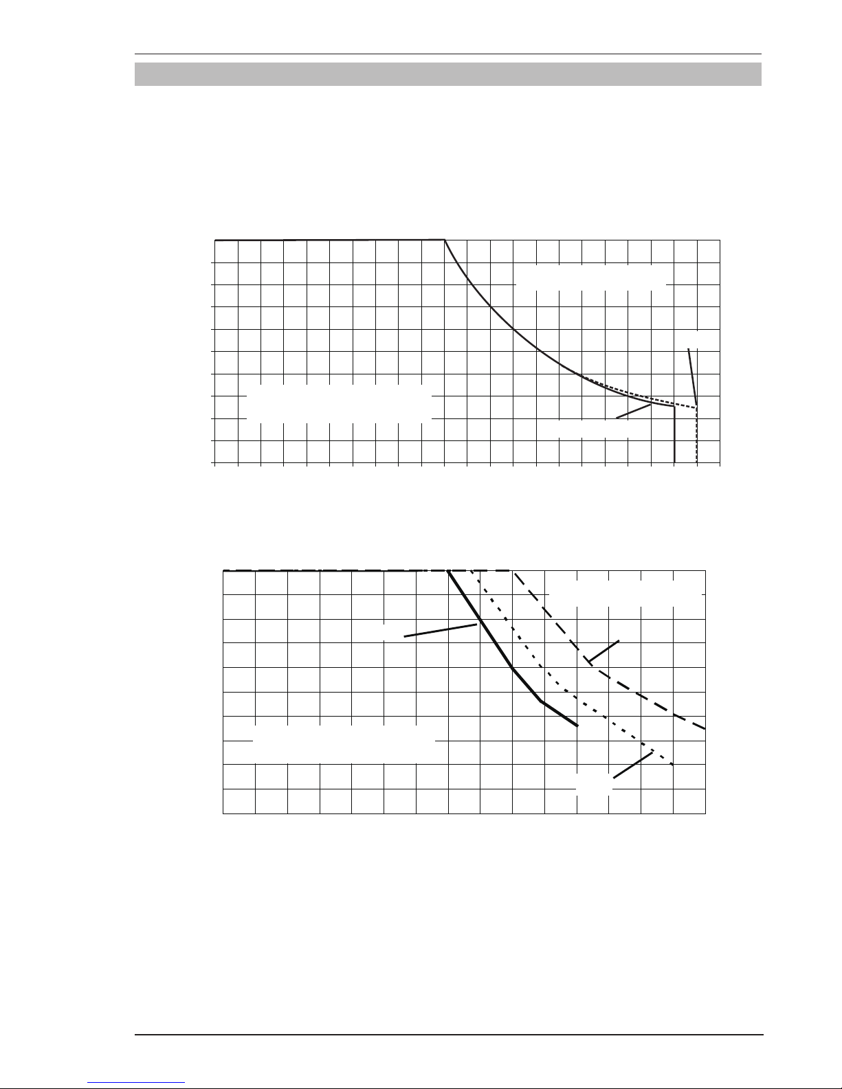
2.08 Duty Cycle
The rated duty cycle of a Welding Power Source, is a statement of the time it may be operated at its rated welding
current output without exceeding the temperature limits of the insulation of the component parts. To explain the
10 minute duty cycle period the following example is used. Suppose a Welding Power Source is designed to operate at a 20% duty cycle, 210 amperes at 24.5 volts. This means that it has been designed and built to provide the
rated amperage (210A) for 2 minutes, i.e. arc welding time, out of every 10 minute period (20% of 10 minutes is
2 minutes). During the other 8 minutes of the 10 minute period the Welding Power Source must idle and allowed
to cool. The thermal cut out will operate if the duty cycle is exceeded.
10 20 30 40 50 60 70 80 90 100 110 120 130 140 150 160 170 180 190 200 210 220
FIREPOWER MST 220i
Welding Current (AMPS)
SAFE OPERATING REGION
(MIG, TIG & STICK)
0
0
10
20
30
40
60
70
50
80
100
90
Duty Cycle (PERCENTAGE)
MIG
STICK / TIG
Art # A-12524
Figure 2-2: Firepower MST 220i Duty Cycle on 208/230VAC
Welding Current (AMPS)
Duty Cycle (PERCENTAGE)
Art # A-12525
0
10
20
30
40
50
60
70
80
90
100
0102030405060708090100 110 120 130140 150
FIREPOWER MST 220i
SAFE OPERATING REGION
(MIG, TIG & STICK)
TIG
STICK
MIG
Figure 2-3: Firepower MST 220i Duty Cycle on 115V AC
Page 28

FIREPOWER MST 220i
INTRODUCTION 2-4 Manual 0-5343
2.09 Specifications
Description Firepower MST 220i Multi Process 3 in 1 Welder
Power Source Part No. 1444-0872
Power Source Dimensions H17.12” x W10.47” x D 24.29” (435mm x 266mm x D617mm)
Power Source Mass 57.3lb (26.5kg)
Cooling Fan Cooled
Welder Type Multi Process Welding System
Applicable Standard CSA E60974-1-00 / UL60974-1
Number of Phases Single Phase
Nominal Supply Voltage 208/230 VAC ± 15% 115VAC± 15%
Nominal Supply Frequency 50/60Hz 50/60HZ
Welding Current Range
MIG Mode
STICK Mode
TIG Mode
10-210 Amps
10-200 Amps
10-200 Amps
10-140 Amps
10-110 Amps
10-150 Amps
Wirefeed Speed Range 100 - 600 IPM 100 - 400 IPM
MIG Welding Voltage Range 14.5 - 24.5V DC 14.5 - 19.5V DC
Nominal OCV 70V DC
Single Phase Generator Requirement 7.5 kVA *3.7 kVA
MIG (GMAW/FCAW) Welding Output, 104°F, 10 min. 210A @ 20%,24.5V
122A @ 60%, 20.1V
95A @ 100%, 18.8V
110A @ 45%,19.5V
99A @ 60%, 19.0V
77A @ 100%, 17.9V
STICK (SMAW) Welding Output,1040°F, 10 min. 200A @ 25%,28.0V
130A @ 60%, 25.2V
101A @ 100%, 24.0V
110A @ 35%,24.4V
90A @ 60%, 23.6V
70A @ 100%, 22.8V
TIG (GTAW) Welding Output, 104°F, 10 min. 200A @ 25%,18.0V
130A @ 60%, 15.2V
101A @ 100%, 14.0V
150A @ 35%,16.0V
115A @ 60%, 14.6V
90A @ 100%, 13.6V
230 VAC ± 15% 208 VAC ± 15% 115 VAC ± 15%
Effective Input Current (I1
eff
)
for MIG (GMAW/FCAW)
for STICK (SMAW)
for LIFT TIG (GTAW)
11.2A
15.8A
11.5A
14.4A
16.8A
11.7A
15.5A
17.8A
17.4A
Maximum Input Current (I1
max
)
for MIG (GMAW/FCAW)
for STICK (SMAW)
for LIFT TIG (GTAW)
25.0A
31.6A
22.9A
32.2A
33.6A
23.3A
24.5A
30.1A
29.4A
Open Circuit Voltage 70 V
Protection Class IP23S
Table 2-1: Firepower MST 220i Specifications
Note 1: The Effective Input Current should be used for the determination of cable size & supply requirements.
Note 2: Motor start fuses or thermal circuit breakers are recommended for this application. Check local re-
quirements for your situation in this regard.
Note 3: Generator Requirements at the Maximum Output Duty Cycle.
* Some 115 VAC, 15 amp/20 amps electrical outlets fitted with GFCI (Ground Fault Circuit Interrupt) protection
against a nuisance trip with this equipment due to worn or out of tolerance components in the GFCI. In such
cases have the 115 VAC, 15 amp/20 amp FGCI electrical outlet replaced by a qualified electrical trades person.
Page 29

FIREPOWER MST 220i
Manual 0-5343 2-5 INTRODUCTION
NOTE
The recommended time delay fuse or circuit breaker size for 115V is 30 amp. An individual branch
circuit capable of carrying 30 amperes and protected by fuses or circuit breaker is recommended for
this application. Fuse size is based on not more than 200 percent of the rated input amperage of the
welding Power Source (Based on Article 630, National Electrical Code)
Firepower continuously strives to produce the best product possible and therefore reserves the right
to change, improve or revise the specifications or design of this or any product without prior notice.
Such updates or changes do not entitle the buyer of equipment previously sold or shipped to the cor
-
responding changes, updates, improvements or replacement of such items
.
The values specified in the table above are optimal values, your values may differ. Individual equipment
may differ from the above specifications due to in part, but not exclusively, to any one or more of the
following; variations or changes in manufactured components, installation and conditions and local
power grid supply conditions.
2.10 Optional Accessories
DESCRIPTION PART NUMBER
TIG Torch, 26V, 12.5 ft, 25mm & Accessory Kit 1444-0021
Firepower Spool Gun, 160A, Euro Back End
1444-0894
Firepower Fusion 220A MIG Gun, 12 ft, Euro Back End
1442-0882
Basic Utility Cart
1444-0900
Single Cylinder Cart
1444-0901
Roll Cage
1442-0902
Foot Control, 15 ft, 8 Pin, for remote amperage control when TIG welding
1442-0025
Drive Roll .023"/.035" (0.6/0.9mm) V groove/solid wire
1444-0913
Drive Roll .023"/.030" (0.6/0.8mm) V groove/solid wire
1444-0914
Drive Roll .030"/.035" (0.8/0.9mm) V knurled groove/flux cored [Fitted]
1444-0915
Ground Clamp & Lead Assembly, 6 ft, 25mm
1443-0495
Electrode Holder & Lead Assembly, 13 ft, 50mm
1443-0494
Firepower GF250-50-580 Argon Flowgauge Regulator
0781-9832
Power Adapter - 230V to 115V, 15A
1444-0911
Spring Adaptor for 8" spools
1444-0912
Gas Hose, 6 ft, Male 5/8-18UNF one end [Fitted]
1443-0490
Firepower Parts Storage Box
1421-0098
Table 2-2: Firepower MST 220i Options and Accessories List
Page 30

FIREPOWER MST 220i
INTRODUCTION 2-6 Manual 0-5343
2.11 Volt-Ampere Curves
Voltage-Amperage Curves shows maximum voltage and amperage output capabilities of welding power source.
Curves of other settings fall between curves shown.
Art # A-11297
Figure 2-4: Firepower MST 220i Volt-Ampere Curves
Page 31

FIREPOWER MST 220i
Manual 0-5343 3-1 INSTALLATION/SETUP
3.01 Environment
This Power Source is designed for use in environments
with increased hazard of electric shock. Additional safety
precautions may be required when using unit in an
environment with increased hazard of electric shock.
Please refer to relevant local standards for further
information prior to using in such areas.
A. Examples of environments with increased hazard of
electric shock are:
1. In locations in which freedom of movement
is restricted, so that the operator is forced to
perform the work in a cramped (kneeling, sitting or lying) position with physical contact with
conductive parts.
2. In locations which are fully or partially limited
by conductive elements, and in which there is
a high risk of unavoidable or accidental contact
by the operator.
3. In wet or damp hot locations where humidity
or perspiration considerably reduces the skin
resistance of the human body and the insulation
properties of accessories.
B. Environments with increased hazard of electric shock
do not include places where electrically conductive parts
in the near vicinity of the operator, which can cause
increased hazard, have been insulated.
3.02 Location
Be sure to locate the welder according to the following
guidelines:
A. In areas, free from moisture and dust.
B. Ambient temperature between 14° F (0° C) to 104°
F (40° C).
C. In areas, free from oil, steam and corrosive gases.
D. In areas, not subjected to abnormal vibration or
shock.
E. In areas, not exposed to direct sunlight or rain.
SECTION 3: INSTALLATION, OPERATION AND SETUP
F. Place at a distance of 12" (305mm) or more from
walls or similar that could restrict natural air flow
for cooling.
G. The enclosure design of this Power Source meets the
requirements of IP23S as outlined in EN 60529. This
provides adequate protection against solid objects
(greater than 1/2", 12mm) and direct protection from
vertical drops. Under no circumstances should the
Power Source be operated or connected in a micro
environment that will exceed the stated conditions.
For further information please refer to EN 60529.
H. Precautions must be taken against the power source
toppling over. The power source must be located on
a suitable horizontal surface in the upright position
when in use.
WARNING
This equipment should be electrically con
-
nected by a qualified electrician.
3.03 Ventilation
!
WARNING
Since the inhalation of welding fumes can
be harmful, ensure that the welding area is
effectively ventilated.
3.04 Electricity Supply
The Electricity Supply voltage
should be within 208/230V AC ± 15% or 115 V AC ±
15%. Too low a supply voltage may cause poor welding
performance in STICK mode such as the arc snuffing
out during welding. Too high a supply voltage will cause
components to overheat and possibly fail. The Welding
power Source must be:
• Correctly installed, if necessary, by a qualied electrician.
• Correctly earthed (electrically) in accordance with
local regulations.
• Connected to the correct size power point and fuse as
per the Specifications on page 2-4.
Page 32

FIREPOWER MST 220i
INSTALLATION/SETUP 3-2 Manual 0-5343
WARNING
The Firepower MST 220i must be electrically connected by a qualified electrical trades-person. Dam
age to the PCA (Power Control Assembly) could occur if 265 VAC or higher is applied to the Primary
Power Cable.
WARNING
ELECTRIC SHOCK can kill; SIGNIFICANT DC VOLTAGE is present after removal of input power. DO NOT
TOUCH live electrical parts.
SHUT DOWN welding power source, disconnect input power employing lockout/tagging procedures. Lock-out/
tagging procedures consist of padlocking line disconnect switch in open position, removing fuses from fuse box,
or shutting OFF and red-tagging circuit breaker or other disconnecting device.
Power Cords Included With Power Supply
Attached to the power supply is an input power cord with a 208/230Volt 50 Amp NEMA 6-50 P for plug. Supplied
adapter allow for connection of the power supply input cable plug to 115 V input power.
Art# A-11275
Figure 3-1: 115 VAC Adapter
Electrical Input Requirements
Operate the welding power source from a single-phase 50/60 Hz, AC power supply. The input voltage must match
one of the electrical input voltages shown on the input data label on the unit nameplate. Contact the local electric
utility for information about the type of electrical service available, how proper connections should be made, and
inspection required. The line disconnect switch provides a safe and convenient means to completely remove all
electrical power from the welding power supply whenever necessary to inspect or service the unit. The Welding
Power Source must be:
Do not connect in input (WHITE or BLACK) conductor to the ground terminal.
Do not connect the ground (GREEN) conductor to an input line terminal.
• Correctly installed, if necessary, by a qualied electrician.
• Correctly earthed (electrically) in accordance with local regulations.
• Connected to the correct size power point, fuse and primary supply lead based on Table 3-1.
Refer to Figure 3-1 and Table 3-1.
Page 33

FIREPOWER MST 220i
Manual 0-5343 3-3 INSTALLATION/SETUP
WARNING
An electrical shock or fire hazard is probable if the following electrical service guide recommendations
are not followed. These recommendations are for a dedicated branch circuit sized for the rated output
and duty cycle of the welding Power Source.
50 / 60 Hz Single Phase Supply
Supply Voltage 208/230V AC 115V AC
Input Current at Maximum Output 32 Amps 30 Amps
Maximum Recommended Fuse* or Circuit Breaker Rating
* Time Delay Fuse, UL class RK5. Refer to UL248
50 Amps 30 Amps
Maximum Recommended Fuse^ or Circuit Breaker Rating
^Normal Operating, UL class K5. Refer to UL248
50 Amps 30 Amps
Minimum Recommended Cord Size 12 AWG 12 AWG
Maximum Recommended Extension Cord Length 50 ft 25 ft
Minimum Recommended Grounding Conductor Size 12 AWG 12AWG
Table 3-1: Electrical Service Guide
CAUTION
The time-delay fuses or circuit breaker of an individual branch circuit may have nuisance tripping when
welding with this product due to the amperage rating of the time-delay fuses or circuit breaker.
Art# A-11240
Primary Power Cable
115
115V,V,
20A,1Ø
15A,1Ø
208/230V, 50A,1Ø
The Adapter enable
connection to all these
power outlets
115 VAC Adapter
Figure 3-2: Electrical Input Connections
Page 34

FIREPOWER MST 220i
INSTALLATION/SETUP 3-4 Manual 0-5343
3.05 Electromagnetic Compatibility
!
WARNING
Extra precautions for Electromagnetic Compatibility may be required when this Welding Power Source
is used in a domestic situation.
A. Installation and Use - Users Responsibility
The user is responsible for installing and using the welding equipment according to the manufacturer’s instructions.
If electromagnetic disturbances are detected then it shall be the responsibility of the user of the welding equipment to resolve the situation with the technical assistance of the manufacturer. In some cases this remedial action
may be as simple as earthing the welding circuit, see NOTE below. In other cases it could involve constructing an
electromagnetic screen enclosing the Welding Power Source and the work, complete with associated input filters.
In all cases, electromagnetic disturbances shall be reduced to the point where they are no longer Troublesome.
NOTE
The welding circuit may or may not be earthed for safety reasons. Changing the earthing arrangements
should only be authorized by a person who is competent to assess whether the changes will increase
the risk of injury, e.g. by allowing parallel welding current return paths which may damage the earth
circuits of other equipment.
B. Assessment of Area
Before installing welding equipment, the user shall make an assessment of potential electromagnetic problems in
the surrounding area. The following shall be taken into account.
1. Other supply cables, control cables, signaling and telephone cables; above, below and adjacent to the welding
equipment.
2. Radio and television transmitters and receivers.
3. Computer and other control equipment.
4. Safety critical equipment, e.g. guarding of industrial equipment.
5. The health of people around, e.g. the use of pace-makers and hearing aids.
6. Equipment used for calibration and measurement.
7. The time of day that welding or other activities are to be carried out.
8. The immunity of other equipment in the environment: the user shall ensure that other equipment being used
in the environment is compatible: this may require additional protection measures.
The size of the surrounding area to be considered will depend on the structure of the building and other activities
that are taking place. The surrounding area may extend beyond the boundaries of the premises.
C. Methods of Reducing Electromagnetic Emissions
1. Electricity Supply
Welding equipment should be connected to the Electricity Supply according to the manufacturer’s
recommendations. If interference occurs, it may be necessary to take additional precautions such as filtering
of the Electricity Supply. Consideration should be given to shielding the supply cable of permanently installed
welding equipment in metallic conduit or equivalent. Shielding should be electrically continuous throughout
its length. The shielding should be connected to the Welding Power Source so that good electrical contact is
maintained between the conduit and the Welding Power Source enclosure.
Page 35

FIREPOWER MST 220i
Manual 0-5343 3-5 INSTALLATION/SETUP
2. Maintenance of Welding Equipment
The welding equipment should be routinely maintained according to the manufacturer’s recommendations. All
access and service doors and covers should be closed and properly fastened when the welding equipment is in
operation. The welding equipment should not be modified in any way except for those changes and adjustments
covered in the manufacturer’s instructions.
3. Welding Cables
The welding cables should be kept as short as possible and should be positioned close together but never
coiled and running at or close to the floor level.
4. Equipotential Bonding
Bonding of all metallic components in the welding installation and adjacent to it should be considered. However,
metallic components bonded to the work piece will increase the risk that the operator could receive a shock by
touching the metallic components and the electrode at the same time. The operator should be insulated from
all such bonded metallic components.
5. Earthing/grounding of the Work Piece
Where the work piece is not bonded to earth for electrical safety, nor connected to earth because of its size and
position, e.g. ship’s hull or building steelwork, a connection bonding the work piece to earth may reduce emissions in some, but not all instances. Care should be taken to prevent the earthing of the work piece increasing
the risk of injury to users, or damage to other electrical equipment. Where necessary, the connection of the
work piece to earth should be made by direct connection to the work piece, but in some countries where direct
connection is not permitted, the bonding should be achieved by suitable capacitance, selected according to
national regulations.
6. Screening and Shielding
Selective screening and shielding of other cables and equipment in the surrounding area may alleviate problems
of interference. Screening the entire welding installation may be considered for special applications.
3.06 Firepower Regulator
Pressure regulator (Figure 3-3) attached to the cylinder valve reduce high cylinder pressures to suitable low working pressures for welding, cutting, and other applications.
LOW PRESSURE
GAUGE (DELIVERY)
HIGH PRESSURE
GAUGE (SUPPLY)
INLET
CONNECTION
OUTLET
CONNECTION
PRESSURE
ADJUSTING
SCREW
A-12435
Figure 3-3: Firepower Regulator
!
WARNING
Use the regulator for the gas and pressure for which it is designed. NEVER alter a regulator for use
with any other gas.
Page 36

FIREPOWER MST 220i
INSTALLATION/SETUP 3-6 Manual 0-5343
NOTE
Regulators purchased with open 1/8”, 1/4”, 3/8”, or 1/2” NPT ports must be assembled to their intended
system.
1. Note the maximum inlet pressure stamped on the regulator. DO NOT attach the regulator to a system that
has a higher pressure than the maximum rated pressure stamped on the regulator.
2. The regulator body will be stamped “IN” or “HP” at the inlet port. Attach the inlet port to the system supply
pressure connection.
3. Wrap pipe threads with Teflon tape 1 1/2 to 2 turns to effect a seal. If other sealants are used, they must
be compatible with the gas that will be used in the system.
4. If gauges are to be attached to the regulator and the regu lator is stamped and listed by a third party (i.e.
“UL” or “ETL”). The following requirements must be met:
a) Inlet gauges over 1000 PSIG (6.87 mPa) shall conform with the requirements of UL 404, “Indicating
Pressure Gauges for Compressed Gas Service.”
b) Low pressure gauges must be UL recognized for the class of regulator they are being used on accord-
ing to UL252A.
!
WARNING
DO NOT use a regulator that delivers pressure exceeding the pressure rating of the downstream equip
ment unless pro visions are made to prevent over-pressurization (i.e. system relief valve). Make sure
the pressure rating of the down stream equipment is compatible with the maximum delivery pressure
of the regulator.
5. Be sure that the regulator has the correct pressure rating and gas service for the cylinder used.
6. Carefully inspect the regulator for damaged threads, dirt, dust, grease, oil, or other flammable substances.
Remove dust and dirt with a clean cloth. Be sure the inlet swivel filter is clean and in place. Attach the
regulator (Figure 3-4) to the cylinder valve. Tighten securely with a wrench.
!
WARNING
DO NOT attach or use the regulator if oil, grease, flamma ble substances or damage is present! Have a
qualified repair technician clean the regulator or repair any damage.
Art # A-12436
Figure 3-4: Regulator to Cylinder Valve
Page 37

FIREPOWER MST 220i
Manual 0-5343 3-7 INSTALLATION/SETUP
7. Before opening the cylinder valve, turn the regulator adjusting screw counterclockwise until there is no
pressure on the adjusting spring and the screw turns freely.
8. Relief Valve (where provided): The relief valve is designed to protect the low pressure side of the regulator
from high pres sures. Relief valves are not intended to protect down stream equipment from high pressures.
!
WARNING
DO NOT tamper with the relief valve or remove it from the regulator.
!
WARNING
Stand to the side of the cylinder opposite the regulator when opening the cylinder valve. Keep the cyl
inder valve between you and the regulator. For your safety, NEVER STAND IN FRONT OF OR BEHIND
A REGULATOR WHEN OPENING THE CYLINDER VALVE!
9. Slowly and carefully open the cylinder valve (Figure 3-5) until the maximum pressure shows on the high
pressure gauge.
Art # A-09828
Figure 3-5: Open Cylinder Valve
10. On all cylinders, except acetylene, open the valve completely to seal the valve packing. On gaugeless
regulators, the indicator will register the cylinder contents open.
11. On acetylene cylinders, open the valve 3/4 of a turn and no more than 1-1/2.
!
WARNING
Acetylene delivery pressure must not exceed 15 PSIG (103 kPa) or 30 PSIG (207 kPa). Acetylene can
dissociate (decompose with explosive violence) above these pressure limits.
CAUTION
Keep the cylinder valve wrench, if one is required, on the cylinder valve to turn OFF the cylinder quickly,
if necessary.
12. Attach the desired downstream equipment.
Page 38

FIREPOWER MST 220i
INSTALLATION/SETUP 3-8 Manual 0-5343
3.07 Leak Testing The System
Leak test the system before putting into operation.
1. Be sure that there is a valve in the downstream equipment to turn OFF the gas flow.
2. With the cylinder valve open, adjust the regulator to deliver the maximum required delivery pressure.
3. Close the cylinder valve.
4. Turn the adjusting screw/knob counterclockwise one turn.
a) If the high-pressure gauge reading drops, there is a leak in the cylinder valve, inlet fitting, or high-
pressure gauge.
b) If the low-pressure gauge drops, there is a leak in the down stream equipment, hose, hose fitting, outlet
fitting or low-pressure gauge. Check for leaks using an approved leak detector solution.
c) If the high-pressure gauge drops and the low-pressure gauge increases at the same time, there is a
leak in the regulator seat.
d) If the regulator requires service or repair, take it to a qualified repair technician.
5. Once leak testing has been performed and there are no leaks in the system, slowly open the cylinder valve
and proceed.
!
WARNING
If a leak has been detected anywhere in the system, dis continue use and have the system repaired. DO
NOT use leaking equipment. Do not attempt to repair a leaking system while the system is under pressure.
3.08 When You Finish Using The Regulator
1. Close the cylinder valve.
2. Open the valve on the downstream equipment. This drains all pressure from the system.
3. Close the valve on the downstream equipment.
4. Turn the adjusting screw counterclockwise to release the ten sion on the adjusting spring.
5. Check the gauges after a few minutes for verification that the cylinder valve is closed completely.
3.09 Storage Of The Regulator
When the regulator is not in use and has been removed from the cylinder, it should be stored in an area where
it will be pro tected from dust, oil, and grease. The inlet and outlet should be capped to protect against internal
contamination and prevent insects from nesting.
Page 39

FIREPOWER MST 220i
Manual 0-5343 3-9 INSTALLATION/SETUP
3.10 Firepower MST 220i Power Source Controls, Indicators And Features
10
Art # A-12526
3
4
5
6
7
89
11
10
12
13
2
1
14
16
15
21
3A
4T
SOFT
HARD
E(S)
22
99
11
2
6
4T
44
77
33
66
88
2
4
8
Figure 3-6: Front and Control Panel Figure 3-7: Rear Panel Connections
Art # A-10938
17
Figure 3-8: Wire Feed Compartment Control
Page 40

FIREPOWER MST 220i
INSTALLATION/SETUP 3-10 Manual 0-5343
1. Power Indicator
The power indicator is illuminated when the correct mains power is applied to the power source and when the
ON/OFF switch located on the rear panel is in the ON position.
2. Thermal Overload Indicator (Fault Indicator)
This welding power source is protected by a self resetting thermostat. The indicator will illuminate if the duty
cycle of the power source has been exceeded. Should the thermal overload indicator illuminate the output
of the power source will be disabled. Once the power source cools down this light will go OFF and the over
temperature condition will automatically reset. Note that the mains power switch should remain in the on
position such that the fan continues to operate thus allowing the unit to cool sufficiently. Do not switch the
unit OFF should a thermal overload condition be present.
3. Digital Wirespeed/Amperage Meter (Left Digital Display)
MIG Mode
This digital meter is used to display the pre-set (preview) Wirefeed Speed in IPM (Inches per minute) in MIG
mode and actual welding amperage of the power source when welding. At times of non-welding, the digital
meter will display a pre-set (preview) value of Wirefeed Speed. This value can be adjusted by varying the
Amperage Control Knob (4).
STICK and LIFT TIG Modes
The digital meter is used to display the pre-set (preview) amperage in STICK / LIFT TIG modes and actual
welding amperage of the power source when welding. At times of non-welding, the amperage meter will
display a pre-set (preview) value in both STICK and LIFT TIG modes. This value can be adjusted by varying
the Amperage Control Knob (4).
When welding, this digital meter will display actual welding amperage in all modes.
At the completion of welding, the digital meter will hold the last recorded amperage value for a period of
approximately 10 seconds in all modes. The amperage meter will hold the value until; (1) any of the front
panel controls are adjusted in which case the unit will revert to preview mode, (2) welding is recommenced,
in which case actual welding amperage will be displayed, or (3) a period of 10 seconds elapses following the
completion of welding in which case the unit will return to preview mode.
NOTE
The preview functionality provided on this power source is intended to act as a guide only. Some dif
ferences may be observed between preview values and actual welding values due to factors including
the mode of welding, differences in consumables/gas mixtures, individual welding techniques and the
transfer mode of the welding arc (ie dip versus spray transfer). Where exact settings are required (in
the case of procedural work), it is recommended that alternate measurement methods be utilized to
ensure output values are accurate.
3A Wirespeed Indicator
The Wirespeed Indicator illuminates when MIG mode is selected to identify that the Digital Wirespeed/Amperage Meter is previewing Wirespeed in IPM (inches per minute).
The Wirespeed Indicator extinguishes when the user is MIG (GMAW/FCAW) welding or depressing the MIG
gun trigger and the Digital Wirespeed/Amperage Meter displays actual welding amperage of the power source.
Page 41

FIREPOWER MST 220i
Manual 0-5343 3-11 INSTALLATION/SETUP
4. Wirespeed/Amperage Control
In MIG mode, the Wirespeed/Amperage control knob adjusts the speed of the wire feed motor (which in turn
adjusts the output current by varying the amount of MIG wire delivered to the welding arc). The optimum wire
speed depends upon the material type and the welding application. The setup chart on the inside of the wire
feed compartment door provides a brief summary of the required settings for a basic range of MIG (GMAW/
FCAW) welding applications.
In STICK and LIFT TIG modes, the Wirespeed/Amperage control knob adjusts the amount of amperage (weld
current) delivered to the welding arc by the Power Source. It directly adjusts the Power Source to deliver the
desired level of weld current.
NOTE
The preview functionality provided on this power source is intended to act as a guide only. Some dif
ferences may be observed between preview values and actual welding values due to factors including
the mode of welding, differences in consumables/gas mixtures, individual welding techniques and the
transfer mode of the welding arc (ie dip versus spray transfer). Where exact settings are required (in
the case of procedural work), it is recommended that alternate measurement methods be utilized to
ensure output values are accurate.
5. MIG Torch Adaptor (Euro Style)
The MIG torch adaptor is the connection point for the MIG welding torch. Connect the torch by pushing the
torch connector into the brass torch adaptor firmly and screwing the plastic torch nut clockwise to secure in
position. To remove the MIG Torch simply reverse these directions.
6. Positive Welding Output Terminal
The positive welding terminal is used to connect the welding output of the power source to the appropriate
welding accessory such as the MIG gun (via the MIG polarity lead), electrode holder lead or work lead. Positive welding current flows from the power source via this dinse type terminal. It is essential, however, that the
male plug is inserted and turned securely to achieve a sound electrical connection.
CAUTION
Loose welding terminal connections can cause overheating and result in the male plug being fused in
the dinse terminal.
7. MIG Polarity Lead
The polarity lead is used to connect the MIG gun to the appropriate positive or negative output terminal (allowing polarity reversal for different welding applications). In general, the polarity lead should be connected
in to the positive welding terminal (+) when using steel, stainless steel or aluminum electrode wire. When
using gasless wire, the polarity lead is generally connected to the negative welding terminal (-). If in doubt,
consult the manufacturer of the electrode wire for the correct polarity. It is essential, however, that the male
plug is inserted and turned securely to achieve a sound electrical connection.
CAUTION
Loose welding terminal connections can cause overheating and result in the male plug being fused in
the dinse terminal.
Page 42
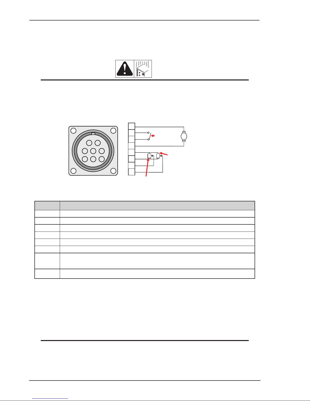
FIREPOWER MST 220i
INSTALLATION/SETUP 3-12 Manual 0-5343
8. Negative Welding Output Terminal
The negative welding terminal is used to connect the welding output of the power source to the appropriate
welding accessory such as the MIG gun (via the MIG polarity lead), TIG torch or work lead. Negative welding
current flows to the power source via this dinse type terminal. It is essential, however, that the male plug is
inserted and turned securely to achieve a sound electrical connection.
CAUTION
Loose welding terminal connections can cause overheating and result in the male plug being fused in
the dinse terminal.
9. Remote Control Socket
The 8 pin Remote Control Socket is used to connect remote control devices to the welding power source. To
make connections, align keyway, insert plug, and rotate threaded collar fully clockwise.
Trigger Switch
Remote Wirespeed in MIG (GMAW/FCAW) mode
Remote Amps in LIFT TIG (GTAW) mode
Remote Volts in
MIG (GMAW/FCAW)
1
2
3
4
5
6
7
8
WV
3
4
5
6
7
8
1
2
Negative
Spool Gun Motor
Positive
Art # A-10421_AC
Figure 3-9: Remote Control Socket
Socket Pin
Function
1 Spool Gun Motor Negative
2
Trigger Switch Input
3
Trigger Switch Input
4
Spool Gun Motor (+24V DC)
5
5k ohm (maximum) connection to 5k ohm remote control potentiometer.
6
Zero ohm (minimum) connection to 5k ohm remote control potentiometer.
7
Wiper arm connection to 5k ohm remote control Wirespeed MIG mode potentiometer. Wiper
arm connection to 5k ohm remote control Amps LIFT TIG mode potentiometer.
8
Wiper arm connection to 5k ohm remote control Volts MIG mode potentiometer.
Table 3- 2
Note that the local/ remote switch (item 18) located in the wirefeed compartment should be set to remote for
the amperage/voltage controls to be operative.
10. Multifunction Control - Voltage, Down Slope & Arc Force
The multifunction control knob is used to adjust Voltage (MIG Mode), Down slope (LIFT TIG Mode) and Arc
Force (STICK Mode) depending on the welding mode selected.
NOTE
The preview functionality provided on this power source is intended to act as a guide only. Some dif
ferences may be observed between preview values and actual welding values due to factors including
the mode of welding, differences in consumables/gas mixtures, individual welding techniques and the
transfer mode of the welding arc (ie dip versus spray transfer). Where exact settings are required (in
the case of procedural work), it is recommended that alternate measurement methods be utilized to
ensure output values are accurate.
Page 43

FIREPOWER MST 220i
Manual 0-5343 3-13 INSTALLATION/SETUP
When MIG Mode is Selected
In this mode the control knob is used to adjust the output voltage of the unit. The welding voltage is increased
by turning the knob clockwise or decreased by turning the knob anti-clockwise. The optimum voltage level
required will dependent on the type of welding application. The setup chart on the inside of the wire feed
compartment door provides a brief summary of the required output settings for a basic range of MIG welding
applications.
When STICK Mode is Selected
In this mode the multifunction control knob is used to adjust arc force. Arc force control provides an adjustable amount of welding force (or “dig”) control. This feature can be particularly beneficial in providing the
operator the ability to compensate for variability in joint fit-up in certain situations with particular electrodes.
In general increasing the arc force control toward ‘10’ (maximum arc force) allows greater penetration control
to be achieved. Arc force is increased by turning the control knob clockwise or decreased by turning the knob
anti-clockwise
When LIFT TIG Mode is Selected
In this mode the multifunction control knob is used to adjust down slope. Down slope allows the user to
select the ramp down time at the completion of the weld. The main function of down slope is to allow the
welding current to be gradually reduced over a pre-set time frame such that the welding pool is given time
to cool sufficiently.
Note that when in 2T normal mode (refer item 12), the unit will enter down slope mode as soon as the trigger
switch is released (ie if the multifunction control knob is set to 5, the unit will ramp down from the present
welding current to zero over 5 seconds). If no down slope time is selected then the welding output will cease
immediately. If the unit is set to 4T latch mode, to enter down slope mode the trigger must be held in for the
selected time period (ie press and release trigger to commence welding, then press and hold trigger again to
enter down slope mode). Should the trigger be released during the down slope phase (4T only), the output
will cease immediately.
11. Arc Control (Inductance)
The arc control operates in MIG mode only and is used to adjust the intensity of the welding arc. Lower arc
control settings make the arc softer with less weld spatter. Higher arc control settings give a stronger driving arc which can increase weld penetration. Soft means maximum inductance while Hard means minimum
inductance.
12. Trigger Mode Control (MIG and LIFT TIG Mode only)
The trigger mode control is used to switch the functionality of the of the torch trigger between 2T (normal)
and 4T (latch mode)
2T (Normal Mode)
In this mode, the torch trigger must remain depressed for the welding output to be active. Press and hold the
torch trigger to activate the power source (weld). Release the torch trigger switch to cease welding.
4T (Latch Mode)
This mode of welding is mainly used for long welding runs to reduce operator fatigue. In this mode the operator can press and release the torch trigger and the output will remain active. To deactivate the power source,
the trigger switch must again be depressed and released, thus eliminating the need for the operator to hold
the torch trigger.
Note that when operating in LIFT TIG mode, the power source will remain activated until the selected downslope
time has elapsed (refer Item 10).
Page 44

FIREPOWER MST 220i
INSTALLATION/SETUP 3-14 Manual 0-5343
13. Process Selection Control
The process selection control is used to select the desired welding mode. Three modes are available, MIG
(GMAW/FCAW), LIFT TIG (GTAW) and STICK (SMAW) modes. Refer to section 3.19 or 3.20 for MIG (GMAW/
FCAW) set up details, section 3.22 for LIFT TIG (GTAW) set-up details or section 3.23 for STICK (SMAW)
set-up details.
Note that when the unit is powered OFF the mode selection control will automatically default to MIG mode.
This is necessary so as to prevent inadvertent arcing should an electrode holder be connected to the unit and
mistakenly be in contact with the work piece during power up.
14. Digital Voltage Meter (Right Digital Display)
MIG Mode
This digital meter is used to display the pre-set (preview) Voltage in MIG mode and actual welding voltage
of the power source when welding. At times of non-welding, the digital meter will display a pre-set (preview)
value of Voltage. This value can be adjusted by varying the Multifunction Control Knob (10).
STICK and LIFT TIG Modes
This digital meter is used to display the Welding Output Terminal Voltage in STICK / LIFT TIG modes during
non-welding or welding. This value cannot be adjusted by varying the Multifunction Control Knob (10).
When welding, this digital meter will display actual welding voltage in all modes.
At the completion of welding, the digital meter will hold the last recorded voltage value for a period of approximately 10 seconds in all modes. The voltage meter will hold the value until; (1) any of the front panel controls
are adjusted in which case the unit will revert to preview mode, (2) welding is recommenced, in which case
actual welding amperage will be displayed, or (3) a period of 10 seconds elapses following the completion of
welding in which case the unit will return to preview mode.
NOTE
The preview functionality provided on this power source is intended to act as a guide only. Some dif
ferences may be observed between preview values and actual welding values due to factors including
the mode of welding, differences in consumables/gas mixtures, individual welding techniques and the
transfer mode of the welding arc (ie dip versus spray transfer). Where exact settings are required (in
the case of procedural work), it is recommended that alternate measurement methods be utilized to
ensure output values are accurate.
15. Gas Inlet (MIG mode only for MIG Gun or Spool Gun operation)
The Gas Inlet connection,5/8-18 UNF female thread is used to supply the appropriate MIG welding gas to the
Power Source. Refer to section 3.18 or 3.19 for MIG (GMAW/FCAW) set up details
!
WARNING
Only Inert Shielding Gases specifically designed for welding applications should be used.
16. ON / OFF Switch
This Single Phase circuit breaker performs a dual function.
It is used to turn the unit ON/OFF and it will also trip in the event of a fault.
WARNING
When the front digital displays are lit, the machine is connected to the Electricity Supply and the internal
electrical components are at Mains voltage potential.
Page 45

FIREPOWER MST 220i
Manual 0-5343 3-15 INSTALLATION/SETUP
17. Wiredrive Motor Circuit Breaker
The 4A Circuit Breaker protects the unit from electrical faults and will operate in the event of a motor overload.
NOTE
If a circuit breaker trips, a short cooling period must be allowed before an attempt is made to reset the
unit by pressing the circuit breaker reset button
.
18. Local / Remote Switch (located in wirefeed compartment)
The local/ remote switch is used only when a remote control device (such as a TIG torch with remote current
control) is fitted to the unit via the remote control socket (item 9). When the local/ remote switch is in the
remote position, the unit will detect a remote device and work accordingly. When in the local mode, the unit
will not detect the remote device and will operate from the power source controls only. Note that the trigger
will operate at all times on the remote control socket irrespective of the position of the local/ remote switch
(ie in both local and remote modes).
Should a remote device be connected and the local/ remote switch set to remote, the maximum setting of
the power source will be determined by the respective front panel control, irrespective of the remote control
device setting. As an example, if the output current on the power source front panel is set to 50% and the
remote control device is set to 100%, the maximum achievable output from the unit will be 50%. Should 100%
output be required, the respective front panel control must be set to 100%, in which case the remote device
will then be able to control between 0-100% output.
19. Burnback Control (located in wirefeed compartment)
The burnback control is used to adjust the amount of MIG wire that protrudes from the MIG gun after the
completion of MIG welding (commonly referred to as stick out). To decrease the burnback time (or lengthen
the amount of wire protruding from the MIG gun at the completing of welding), turn the burnback control
knob anti-clockwise. To increase the burnback time (or shorten the amount of wire protruding from the torch
at the completing of welding), turn the Burnback Control knob clockwise.
20. MIG Gun & Spool Gun Switch
The MIG Gun / Spool Gun switch is used to switch welding mode between MIG Gun functionality and Spool
Gun functionality
21. Cooling Fan
The Firepower MST 220i is designed with an intelligent fan control. When the 220i is switched ON the cooling
fan will come ON for approximately 3 seconds then automatically switch the fan OFF. The cooling fan will remain
OFF until it is required for cooling purposes. This has two main advantages; (1) to minimize power consumption, and (2) to minimize the amount of contaminants such as dust that are drawn into the power source.
Note in STICK mode the fan operates continuously.
Page 46
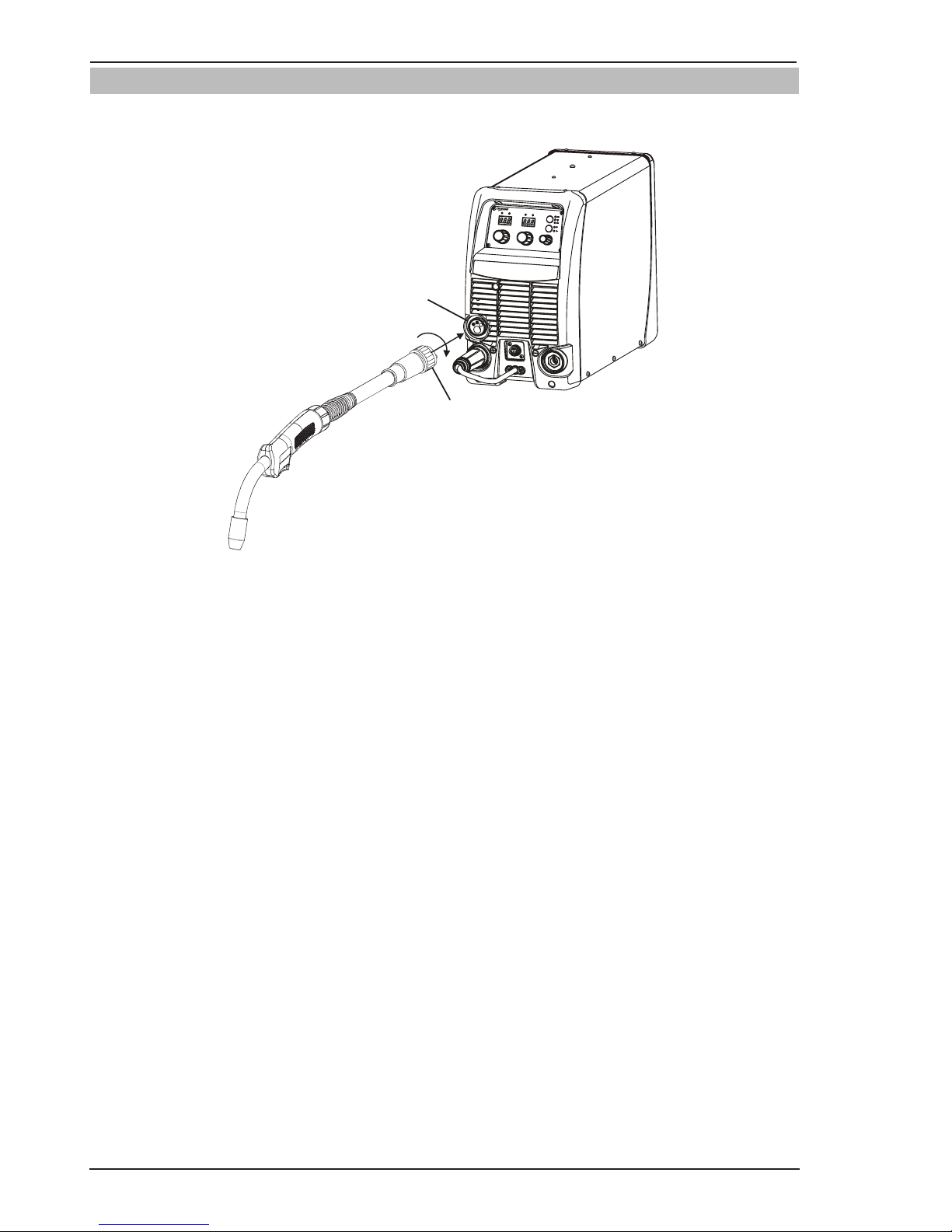
FIREPOWER MST 220i
INSTALLATION/SETUP 3-16 Manual 0-5343
3.11 Attaching the Firepower Fusion 220A MIG Gun
Fit the MIG Torch to the power source by pushing the MIG torch connector into the MIG torch adaptor and screwing the plastic torch nut clockwise to secure the MIG torch to the MIG torch adaptor.
Art # A-12527
MIG Torch Adaptor
MIG Torch Connector
Figure 3-10: Attaching MIG Gun
Page 47
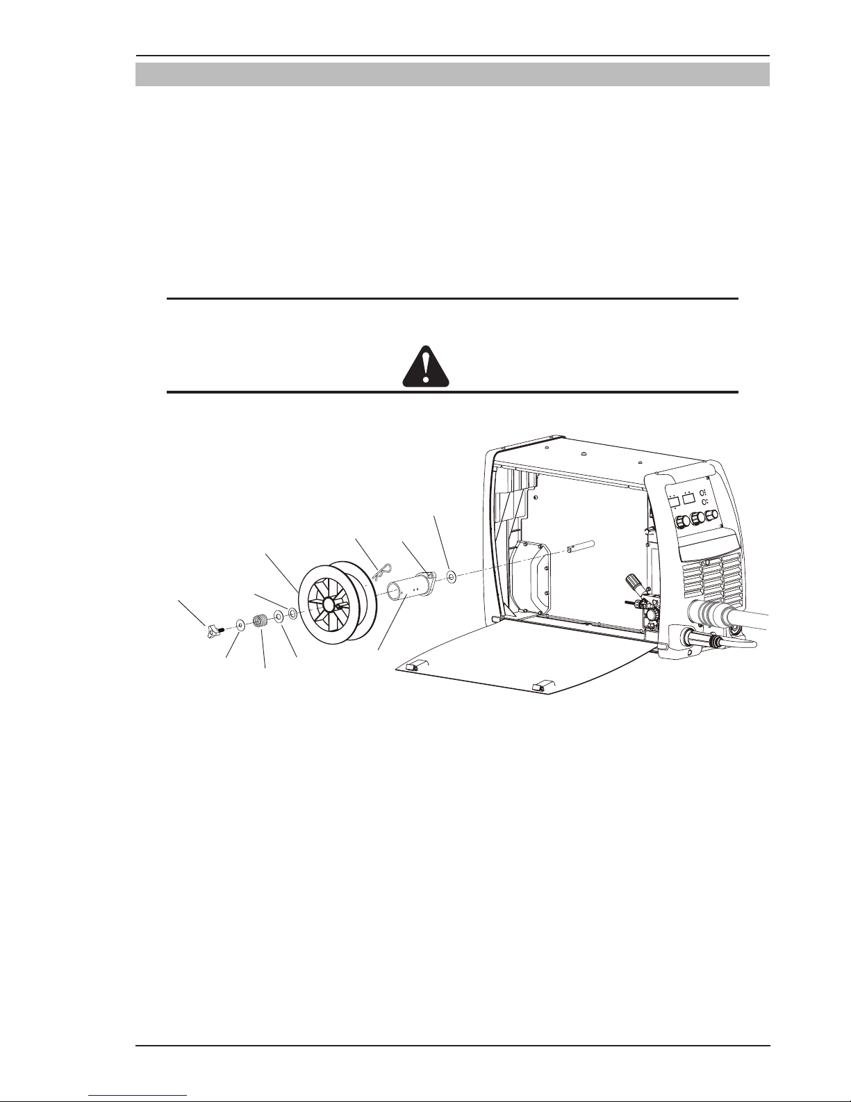
FIREPOWER MST 220i
Manual 0-5343 3-17 INSTALLATION/SETUP
3.12 Installing 33/44 lb Spool (12" diameter)
As delivered from the factory, the unit is fitted with a Wire Spool Hub which accepts a Spool of 33/44 lb. or 12"
diameter.
Installation of wire spool, Refer to Figure 3-11.
1. Remove Wire Spool Hub Retaining Clip. Grasp the loop and pull.
2. Place Wire Spool onto the hub, loading it so that the wire will feed off the bottom of the spool as the spool
rotates counter clockwise. Make sure to align the spool alignment pin on the hub with the mating hole in
the wire spool.
3. Replace the Wire Spool Hub Retaining Clip in the set of holes closest to the spool.
NOTE
The Hub tension has been pre-adjusted at the factory. However if adjustment is required, refer to Sec
-
tion 3.18
CAUTION
Use care in handling the spooled wire as it will tend to “unravel” when loosened from the spool. Grasp
the end of the wire firmly and don’t let go of it.
Wire Spool
Hub Nut
Spring
33/44 lb (12")
Wire Spool
Retaining Clip
Use inner holes on
Spool Hub
Flat Washer
Small Hole
Fiber Washer
Spool Hub
Keyed Washer
Flat Washer
Large Hole
Pin
Art # A-12528
Figure 3-11: 33/44 lb (12") Spool Installation
Page 48

FIREPOWER MST 220i
INSTALLATION/SETUP 3-18 Manual 0-5343
3.13 Installing 12.5 lb Spool ( 8" diameter)
In order to fit a 12.5 lb spool (8" diameter) assemble parts in the sequence shown in Figure 3-9.
Installation of wire spool:
1. Remove Wire Spool Hub Retaining Clip. Grasp the loop and pull.
2. Place Wire Spool onto the hub, loading it so that the wire will feed off the bottom of the spool as the spool
rotates counter clockwise. Make sure to align the spool alignment pin on the hub with the mating hole in
the wire spool.
3. Replace the Wire Spool Hub Retaining Clip in the set of holes closest to the spool.
NOTE
The Hub tension has been pre-adjusted at the factory. However if adjustment is required, refer to sec
-
tion 3.18.
CAUTION
Use care in handling the spooled wire as it will tend to “unravel” when loosened from the spool. Grasp
the end of the wire firmly and don’t let go of it.
Wire Spool
Hub Nut
Spring
12.5 lb (8")
Wire Spool
Retaining Clip
Use inner holes on
Spool Hub
Flat Washer
Small Hole
Fiber Washer
Spool Hub
Keyed Washer
Flat Washer
Large Hole
Pin
Art # A-12529
Figure 3-12: 12.5lb (8") Spool Installation
Page 49

FIREPOWER MST 220i
Manual 0-5343 3-19 INSTALLATION/SETUP
3.14 Installing 1 lb Spool (4" diameter)
In order to fit a 1 lb spool (4" diameter) assemble parts in the sequence shown in Figure 3-13.
Installation of wire spool:
1. Remove Wire Spool Hub Retaining Clip. Grasp the loop and pull.
2. Place Fiber Washer and Large Spring onto the Shaft, then load the Wire Spool on the Shaft so that the wire
will feed off the bottom of the spool as spool rotates counter clockwise.
3. Then place Flat Washer Large Hole, Keyed Washer, Spring, Flat Washer Small Hole as shown in Figure
3-13. Finally secure with Wire Spool Hub Nut.
NOTE
The Hub tension has been pre-adjusted at the factory. However if adjustment is required, refer to sec
-
tion 3.18.
CAUTION
Use care in handling the spooled wire as it will tend to “unravel” when loosened from the spool. Grasp
the end of the wire firmly and don’t let go of it.
Fiber
Washer
Art # A-12530
Wire Spool
Hub Nut
Spring
1lb (4") Diameter
Wire Spool
Flat Washer
Small Hole
Keyed Washer
Flat Washer
Large Hole
Large
Spring
Figure 3-13: 1 lb (4") Spool Installation
Page 50

FIREPOWER MST 220i
INSTALLATION/SETUP 3-20 Manual 0-5343
3.15 Inserting Wire Into The Wire Feed Mechanism
Release the tension from the pressure roller by turning the adjustable wire drive tension knob in an anti-clockwise
direction. Then to release the pressure roller arm push the tension screw toward the back of the machine which
releases the pressure roller arm (Figure 3-14). With the MIG welding wire feeding from the bottom of the spool
(Figure 3-15) pass the electrode wire through the inlet guide, between the rollers, through the outlet guide and into
the MIG gun. Re-secure the pressure roller arm and wire drive tension screw and adjust the pressure accordingly
(Figure 3-14). Remove the contact tip from the MIG gun. With the MIG gun lead reasonably straight, feed the wire
through the MIG gun by depressing the trigger switch. Fit the appropriate Velocity contact tip.
WARNING
Before connecting the work clamp to the work make sure the Electricity Supply is switched OFF.
The electrode wire will be at welding voltage potential while it is being feed through the system.
Keep MIG gun away from eyes and face.
Wire Drive Tension Knob
Pressure Arm
Outlet Guide
Inlet Guide
Art # A-12531
Figure 3-14: Wire Drive Assembly Components
MIG Welding Wire
Art # A-12532
Figure 3-15: MIG Welding Wire - Installation
Page 51

FIREPOWER MST 220i
Manual 0-5343 3-21 INSTALLATION/SETUP
3.16 Feed Roller Pressure Adjustment
The pressure (top) roller applies pressure to the grooved feed roller via an adjustable pressure screw. These
devices should be adjusted to a minimum pressure that will provide satisfactory WIREFEED without slippage. If
slipping occurs, and inspection of the wire contact tip reveals no wear, distortion or burn back jam, the conduit
liner should be checked for kinks and clogging by metal flakes and swarf. If it is not the cause of slipping, the feed
roll pressure can be increased by rotating the pressure screw clockwise.
WARNING
Before changing the feed roller ensure that the Electricity Supply to the power source is switched OFF.
CAUTION
The use of excessive pressure may cause rapid wear of the feed rollers, shafts and bearing.
3.17 Changing the Feed Roll
To change feed roll remove the feed roll retaining screw by turning in an anti-clockwise direction. Once the feed roll
is removed then to replace feed roll simply reverse these directions. Note: Be sure not to lose key that is located
on Drive Motor Shaft. This key must align with drive roll groove for proper operation.
A dual groove feed roller is supplied as standard. It can accommodate 0.6/0.8mm diameter hard wires. Select the
roller required with the chosen wire size marking facing outward.
GROOVE “B”GROOVE “A”
GROOVE “A” SIZE
GROOVE “B” SIZE
A-09583
Figure 3-16: Dual Groove Feed Roller
Feed Roll Retaining Screw
Art # A-12533
Figure 3-17: Changing the Feed Roll
Page 52

FIREPOWER MST 220i
INSTALLATION/SETUP 3-22 Manual 0-5343
3.18 Wire Reel Brake
The wire reel hub incorporates a friction brake which is adjusted during manufacture for optimum braking.
If it is considered necessary, adjustment can be made by turning the Thumb Screw inside the open end of the
hub clockwise to tighten the brake. Correct adjustment will result in the wire reel circumference continuing no
further than 1/8"-3/16" (3-5mm) after release of the trigger. The electrode wire should be slack without becoming
dislodged from wire spool.
CAUTION
Overtension of brake will cause rapid wear of mechanical WIREFEED parts, overheating of electrical
componentry and possibly an increased incidence of electrode wire Burnback into contact tip.
Spool Hub Tension
Thumb Screw
Art # A-12534
Figure 3-18: Wire Reel Brake
3.19 Setup For MIG (GMAW) Welding With Gas Shielded MIG Wire
A. Select MIG mode with the process selection control. (Refer to Section 3.10 for further information)
B. Connect the MIG polarity lead to the positive welding terminal (+). If in doubt, consult the electrode wire manu-
facturer. Welding current flows from the Power Source via dinse type terminals. It is essential, however, that
the male plug is inserted and turned securely to achieve a sound electrical connection.
C. Fit the MIG gun to the power source. (Refer to section 3.11 Attaching the Firepower Fusion 220A MIG Gun).
D. Connect the work lead to the negative welding terminal (-). If in doubt, consult the electrode wire manufacturer.
Welding current flows from the Power Source via dinse type terminals. It is essential, however, that the male
plug is inserted and turned securely to achieve a sound electrical connection.
E. Fit the welding grade shielding gas regulator/flowmeter to the shielding gas cylinder (refer to Section 3.06)
then connect the shielding gas hose from the rear of the power source to the regulator/flowmeter outlet.
F. Refer to the Weld Guide located on the inside of the wirefeed compartment door for further information.
G. Switch the LOCAL/REMOTE switch inside the
wire feed compartment to LOCAL to use the
Power Sources Wirespeed and Voltage controls.
H. Switch the MIG GUN/SPOOL GUN switch inside
the wire feed compartment to MIG GUN.
Page 53

FIREPOWER MST 220i
Manual 0-5343 3-23 INSTALLATION/SETUP
!
WARNING
Before connecting the work clamp to the work make sure the Electricity Supply is switched OFF.
Secure the welding grade shielding gas cylinder in an upright position by chaining it to a suitable sta
-
tionary support to prevent falling or tipping.
CAUTION
Loose welding terminal connections can cause overheating and result in the male plug being fused in
the terminal.
Remove any packaging material prior to use. Do not block the air vents at the front or rear of the Weld
-
ing Power Source.
Positive Welding
Terminal (+)
MIG Polarity Lead
Work Lead
Negative Welding
Terminal (-)
Art # A-12535
Shielding Gas Hose Fitted with Quick Connect
MIG Gun
Figure 3-19: Setup for MIG Welding with Gas Shielded MIG Wire
Page 54

FIREPOWER MST 220i
INSTALLATION/SETUP 3-24 Manual 0-5343
3.20 Setup For MIG (FCAW) Welding With Flux Core (Gasless) Wire
A. Select MIG mode with the process selection control (refer to Section 3.10 for further information).
B. Connect the MIG polarity lead to the negative welding terminal (-). If in doubt, consult the electrode wire
manufacturer. Welding current flows from the power source via dinse type terminals. It is essential, however,
that the male plug is inserted and turned securely to achieve a sound electrical connection.
C. Connect the work lead to the positive welding terminal (+). If in doubt, consult the electrode wire manufacturer.
Welding current flows from the power source via dinse type terminals. It is essential, however, that the male
plug is inserted and turned securely to achieve a sound electrical connection.
D. Refer to the Weld Guide located on the inside of the wirefeed compartment door for further information.
E. Switch the LOCAL/REMOTE switch inside the
wire feed compartment to LOCAL to use the
Power Sources Wirespeed and Voltage controls.
F. Switch the MIG GUN/SPOOL GUN switch inside
the wire feed compartment to MIG GUN.
WARNING
Before connecting the work clamp to the work make sure the Electricity Supply is switched OFF.
CAUTION
Loose welding terminal connections can cause overheating and result in the male plug being fused in
the terminal.
Remove any packaging material prior to use. Do not block the air vents at the front or rear of the Weld
-
ing Power Source.
Work Lead
Positive Welding
Terminal (+)
Negative Welding
Terminal (-)
MIG Polarity Lead
Art # A-12536
MIG Gun
Figure 3-20: Setup for MIG Welding with Gasless MIG Wire
Page 55

FIREPOWER MST 220i
Manual 0-5343 3-25 INSTALLATION/SETUP
3.21 Setup For SPOOL GUN MIG (GMAW) Welding With Gas Shielded MIG Wire
Select the Process Selection Control to MIG for Spool Gun welding.
For setup and operation of the spool gun, please refer to the spool gun operations manual.
Switch the MIG GUN/SPOOL GUN switch inside the wire feed compartment to SPOOL GUN.
Connect the shielding gas for the to the Shielding Gas Inlet on the rear panel of the Power Source.
1. Make sure the welding power source is turned
OFF before connecting the welding gun.
NOTE
If the Firepower MST 220 has already been
setup for MIG Welding you will have to re
move the MIG Gun and retract the welding
wire out of the wirefeeder before beginning
the next step.
2. Insert the back end of the Spool gun into the
MIG Gun connector and tighten the Locking
Nut to secure the Spool gun in the MIG Gun
Adapter.
3. Connect gas supply fitting and tighten with a
wrench.
4. Align Control Plug to panel fitting and tighten
securely.
MIG Gun Adaptor
Spool Gun
Locking Nut
Art #
A-12537
Page 56
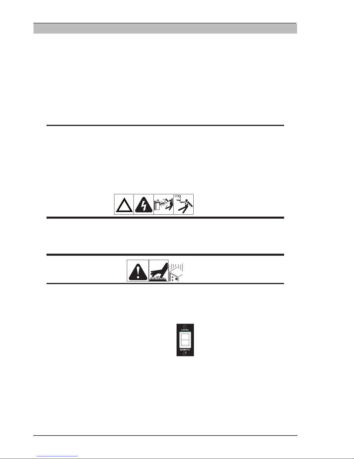
FIREPOWER MST 220i
INSTALLATION/SETUP 3-26 Manual 0-5343
3.22 Setup For LIFT TIG (GTAW) Welding
A. Select LIFT TIG mode with the process selection control (refer to Section 3.10 for further information).
B. Connect the TIG Torch to the negative welding terminal (-). Welding current flows from the power source via
dinse type terminals. It is essential, however, that the male plug is inserted and turned securely to achieve a
sound electrical connection.
C. Connect the work lead to the positive welding terminal (+). Welding current flows from the Power Source via
dinse type terminals. It is essential, however, that the male plug is inserted and turned securely to achieve a
sound electrical connection.
D. Connect the TIG torch trigger switch via the 8 pin socket located on the front of the power source as shown
below. The TIG torch will require a trigger switch to operate in LIFT TIG Mode.
NOTE
A 26V TIG torch with an 8 pin plug must be used to turn the weld current ON/OFF via the TIG torch
trigger switch to TIG weld OR a Foot Control with an 8 pin plug must be used to turn the weld current
ON/OFF as well as providing remote control of the weld current.
E. Fit the welding grade shielding gas regulator/flowmeter to the shielding gas cylinder (refer to Section 3.06)
then connect the shielding gas hose from the TIG torch to the regulator/flowmeter outlet. Note that the TIG
torch shielding gas hose is connected directly to the regulator/flowmeter. The power source is not fitted with
a shielding gas solenoid to control the gas flow in LIFT TIG mode therefore the TIG torch will require a gas
valve.
!
WARNING
Before connecting the work clamp to the work and inserting the electrode in the TIG Torch make sure
the Electricity Supply is switched OFF.
Secure the welding grade shielding gas cylinder in an upright position by chaining it to a stationary
support to prevent falling or tipping.
CAUTION
Remove any packaging material prior to use. Do not block the air vents at the front or rear of the Weld
-
ing Power Source.
Loose welding terminal connections can cause overheating and result in the male plug being fused in
the terminal.
F. Switch the LOCAL/REMOTE switch inside the
wire feed compartment to LOCAL to use the
Power Sources Amperage control or REMOTE
for remote amperage using a Foot Control.
Page 57

FIREPOWER MST 220i
Manual 0-5343 3-27 INSTALLATION/SETUP
Positive Welding
Terminal (+)
Negative Welding
Terminal (-)
Work Lead
TIG Torch
TIG Remote Control
Art # A-12538
Connect to shielding gas
regulator/flow gauge.
Secure the gas cylinder
in an upright position by
chaining it to a stationary
support to prevent falling
or tipping.
Note: A 26V TIG torch with an 8 pin plug
must be used to turn the weld current on/off
via the TIG torch trigger switch to TIG weld
OR a Foot Control with an 8 pin plug must be
used to turn the weld current on/off as well as
providing remote control of the weld current.
Figure 3-22: Setup for TIG Welding
Page 58
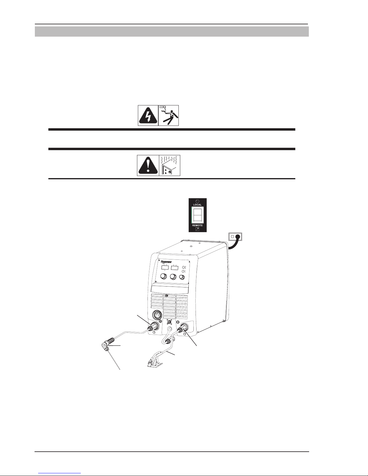
FIREPOWER MST 220i
INSTALLATION/SETUP 3-28 Manual 0-5343
3.23 Setup For STICK (SMAW) Welding
A. Connect the Electrode Holder lead to the positive welding terminal (+). If in doubt, consult the electrode manu-
facturer. Welding current flows from the Power Source via dinse type terminals. It is essential, however, that
the male plug is inserted and turned securely to achieve a sound electrical connection.
B. Connect the work lead to the negative welding terminal (-). If in doubt, consult the electrode manufacturer.
Welding current flows from the power source via dinse type terminals. It is essential, however, that the male
plug is inserted and turned securely to achieve a sound electrical connection.
C. Select STICK mode with the process selection control (refer to Section 3.10 for further information).
WARNING
Before connecting the work clamp to the work and inserting the electrode in the electrode holder make
sure the Electricity Supply is switched OFF.
CAUTION
Remove any packaging material prior to use. Do not block the air vents at the front or rear of the
Welding Power Source.
D. Switch the LOCAL/REMOTE switch inside the wire
feed compartment to LOCAL to use the Power Sources
Amperage control or REMOTE for remote amperage
control using a Hand Pendant Control.
Positive Welding
Terminal (+)
Negative Welding
Terminal (-)
Work Lead
Electrode Holder
Art # A-12539
Figure 3-23: Setup for Manual Arc Welding
Page 59

FIREPOWER MST 220i
Manual 0-5343 4-1 BASIC WELDING
SECTION 4:
BASIC WELDING GUIDE
4.01 MIG (GMAW/FCAW) Basic Welding
Technique
Two different welding processes are covered in this section GMAW and FCAW, with the intention of providing
the very basic concepts in using the MIG mode of welding, where a MIG Gun is hand held, and the electrode
(welding wire) is fed into a weld puddle, and the arc is
shielded by an inert welding grade shielding gas or inert
welding grade shielding gas mixture.
GAS METAL ARC WELDING (GMAW): This process,
also known as MIG welding, CO
2
welding, Micro Wire
Welding, short arc welding, dip transfer welding, wire
welding etc., is an electric arc welding process which
fuses together the parts to be welded by heating them
with an arc between a solid continuous, consumable
electrode and the work. Shielding is obtained from an
externally supplied welding grade shielding gas or welding grade shielding gas mixture. The process is normally
applied semi automatically; however the process may be
operated automatically and can be machine operated.
The process can be used to weld thin and fairly thick
steels, and some non-ferrous metals in all positions.
Art # A-8991_AB
Shielding Gas
Molten Weld Metal
Solidified
Weld Metal
Nozzle
Electrode
Arc
Base Metal
GMAW Process
Figure 4-1
FLUX CORED ARC WELDING (FCAW): This is an electric
arc welding process which fuses together the parts to be
welded by heating them with an arc between a continuous flux filled electrode wire and the work. Shielding is
obtained through decomposition of the flux within the
tubular wire. Additional shielding may or may not be
obtained from an externally supplied gas or gas mixture.
The process is normally applied semi automatically;
however the process may be applied automatically or
by machine. It is commonly used to weld large diameter
electrodes in the flat and horizontal position and small
electrode diameters in all positions. The process is
used to a lesser degree for welding stainless steel and
for overlay work.
Art # A-08992_AB
Molten
Slag
Nozzle
(Optional)
FCAW Process
Flux Cored
Electrode
Arc
Shielding Gas
(Optional)
Slag
Molten Metal
Base Metal
Solidified
Weld Metal
Figure 4-2
Position of MIG Gun
The angle of MIG Gun to the weld has an effect on the
width of the weld.
Push
Vertical
Drag/Pull
Art # A-07185_AB
Figure 4-3
The MIG Gun should be held at an angle to the weld joint.
(See Secondary Adjustment Variables below)
Hold the MIG Gun so that the welding seam is viewed at
all times. Always wear the welding helmet with proper
filter lenses and use the proper safety equipment.
CAUTION
Do NOT pull the MIG Gun back when the
arc is established. This will create excessive
wire extension (stick-out) and make a very
poor weld.
The electrode wire is not energized until the MIG Gun
trigger switch is depressed. The wire may therefore be
placed on the seam or joint prior to lowering the helmet.
Direction of
Travel
5° to 15°
Longitudinal
Angle
90°
Transverse
Angle
Art # A-08993
Figure 4-4
Page 60
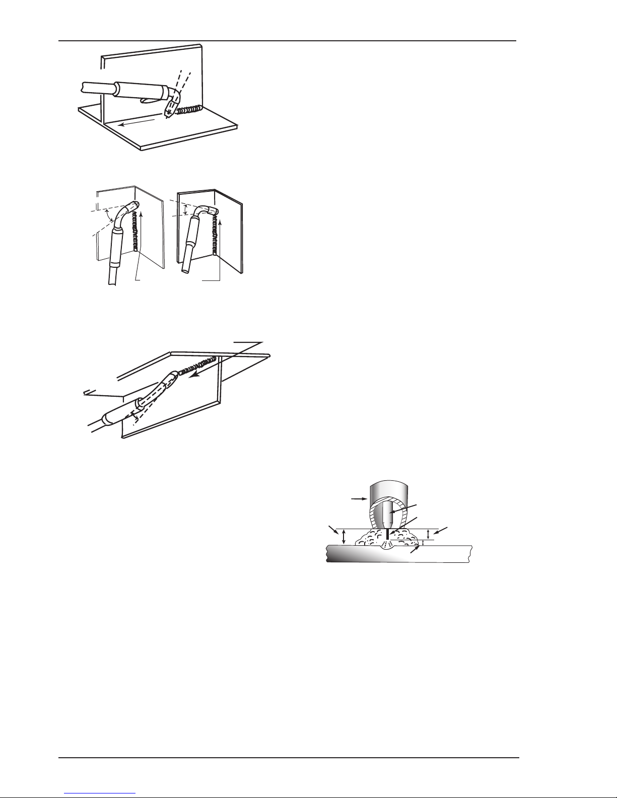
FIREPOWER MST 220i
BASIC WELDING 4-2 Manual 0-5343
Direction of
Travel
5° to 15°
Longitudinal Angle
30° to 60°
Transverse Angle
Art # A-08994
Figure 4-5
Vertical Fillet Welds
Art # A-08995
30° to 60°
Transverse
Angle
30° to 60°
Transverse
Angle
Direction of Travel
10°
Longitudinal Angle
10° to 20° Longitudinal
Angle
Figure 4-6
Art # A-08996
30° to 60°
Transverse Angle
Direction of Travel
5° to 15°
Longitudinal
Angle
Figure 4-7
Distance from the MIG Gun Nozzle to the Work
Piece
The electrode wire stick out from the MIG Gun nozzle
should be between 3/8" - 3/4" (10 - 20 mm). This distance may vary depending on the type of joint that is
being welded.
Travel Speed
The speed at which the molten pool travels influences
the width of the weld and penetration of the welding run.
MIG Welding (GMAW) Variables
Most of the welding done by all processes is on carbon
steel. The items below describe the welding variables in
short-arc welding of .023 - 1/4" (0.6 mm - 6.4 mm) mild
sheet or plate. The applied techniques and end results
in the GMAW process are controlled by these variables.
Preselected Variables
Preselected variables depend upon the type of material
being welded, the thickness of the material, the welding
position, the deposition rate and the mechanical properties. These variables are:
• Type of electrode wire
• Size of electrode wire
• Type of gas (not applicable for FCAW self shielding
wires)
• Gas flow rate (not applicable for FCAW self shielding wires)
Primary Adjustable Variables
These control the process after preselected variables
have been found. They control the penetration, bead
width, bead height, arc stability, deposition rate and
weld soundness. They are:
• Arc Voltage
• Welding current (wire feed speed)
• Travel speed
Secondary Adjustable Variables
These variables cause changes in primary adjustable
variables which in turn cause the desired change in the
bead formation. They are:
1. Sick-out (distance between the end of the contact tube (tip) and the end of the electrode wire).
Maintain at about 3/8" (10 mm) stick-out
2. Wire Feed Speed. Increase in wire feed speed
increases weld current, Decrease in wire feed
speed decreases weld current.
Art # A-08997_AD
Gas Nozzle
Electrode Wire
Average Arc Length
Electrode Stick-Out
Tip to
Work Distance
Actual Stick-out
Contact Tip (Tube)
Figure 4-8
3. Nozzle Angle. This refers to the position of the
MIG Gun in relation to the joint. The transverse
angle is usually one half the included angle between plates forming the joint. The longitudinal
angle is the angle between the centre line of the
MIG Gun and a line perpendicular to the axis of
the weld. The longitudinal angle is generally
called the Nozzle Angle and can be either trailing (pulling) or leading (pushing). Whether the
operator is left handed or right handed has to be
considered to realize the effects of each angle
in relation to the direction of travel.
Page 61
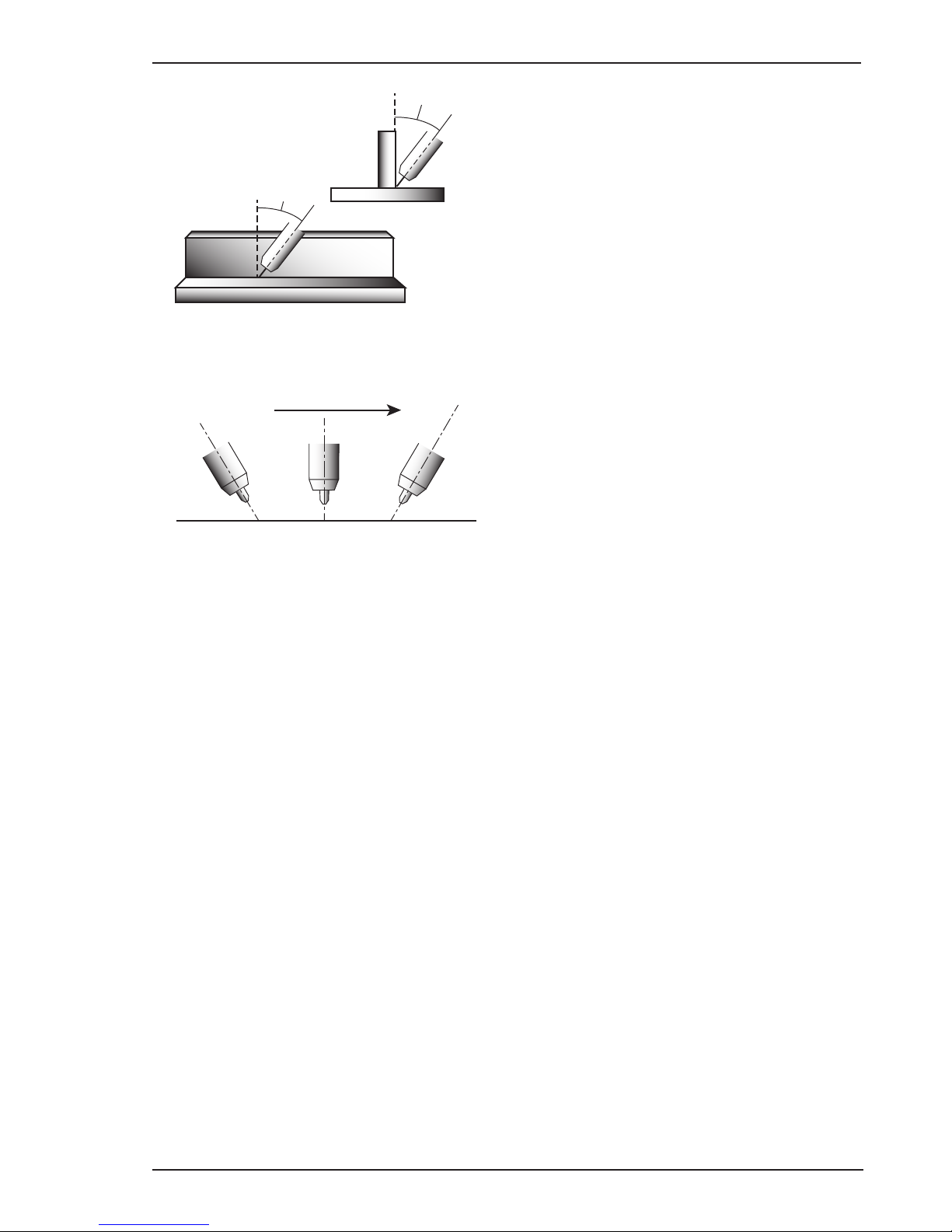
FIREPOWER MST 220i
Manual 0-5343 4-3 BASIC WELDING
Transverse and Longitudinal
Nozzle Axes
Art # A-08998_AB
Longitudinal
Angle
Axis of Weld
Transverse
Angle
Figure 4-9
Art # A-08999_AC
Nozzle Angle, Right Handed Operator
Direction of Gun Travel
Leading or “Pushing”
Angle
(Forward Pointing)
Trailing or “Pulling”
Angle
(Backward Pointing)
90°
Figure 4-10
Establishing the Arc and Making Weld Beads
Before attempting to weld on a finished piece of work,
it is recommended that practice welds be made on a
sample metal of the same material as that of the finished piece.
The easiest welding procedure for the beginner to
experiment with MIG welding is the flat position. The
equipment is capable of flat, vertical and overhead
positions.
For practicing MIG welding, secure some pieces of
1/16" or 3/16" (1.6 mm or 5.0 mm) mild steel plate 6" x
6" (150 mm x 150 mm). Use .035" (0.9 mm) flux cored
gasless wire or a solid wire with shielding gas.
Setting of the Power Source
Power source setting requires some practice by the
operator, as the welding plant has two control settings
that have to balance. These are the Wirespeed control
(refer to section 3.06.4) and the welding Voltage Control (refer to section 3.06.10). The welding current is
determined by the Wirespeed control, the current will
increase with increased Wirespeed, resulting in a shorter
arc. Less wire speed will reduce the current and lengthen
the arc. Increasing the welding voltage hardly alters the
current level, but lengthens the arc. By decreasing the
voltage, a shorter arc is obtained with a little change in
current level.
When changing to a different electrode wire diameter,
different control settings are required. A thinner electrode wire needs more Wirespeed to achieve the same
current level.
A satisfactory weld cannot be obtained if the Wirespeed
and Voltage settings are not adjusted to suit the electrode wire diameter and the dimensions of the work
piece.
If the Wirespeed is too high for the welding voltage,
“stubbing” will occur as the wire dips into the molten
pool and does not melt. Welding in these conditions
normally produces a poor weld due to lack of fusion.
If, however, the welding voltage is too high, large drops
will form on the end of the wire, causing spatter. The
correct setting of voltage and Wirespeed can be seen
in the shape of the weld deposit and heard by a smooth
regular arc sound. Refer to the Weld Guide located on
the inside of the wirefeed compartment door for setup
information.
Electrode Wire Size Selection
The choice of Electrode wire size and shielding gas used
depends on the following:
• Thickness of the metal to be welded
• Type of joint
• Capacity of the wire feed unit and Power Source
• The amount of penetration required
• The deposition rate required
• The bead prole desired
• The position of welding
• Cost of the wire
Page 62

FIREPOWER MST 220i
BASIC WELDING 4-4 Manual 0-5343
Firepower MIG, Lift TIG, Stick Wire Selection Chart
Art # A-12540
Table 4-1
NOTE
Please refer to the inside panel of the machine for the same chart.
Page 63

FIREPOWER MST 220i
Manual 0-5343 4-5 BASIC WELDING
4.02 MIG (GMAW/FCAW) Welding Troubleshooting
Solving Problems Beyond the Welding Terminals
The general approach to fix MIG (GMAW/FCAW) welding problems is to start at the wire spool then work through
to the MIG Gun. There are two main areas where problems occur with GMAW; Porosity and Inconsistent wire feed.
Solving Problems Beyond the Welding Terminals - Porosity
When there is a gas problem the result is usually porosity within the weld metal. Porosity always stems from some
contaminant within the molten weld pool which is in the process of escaping during solidification of the molten
metal. Contaminants range from no gas around the welding arc to dirt on the work piece surface. Porosity can
be reduced by checking the following points.
FAULT/CONDITION CAUSE
1 Shielding gas cylinder contents
and flow meter.
Ensure that the shielding gas cylinder is not empty and the
flow meter is correctly adjusted to 31.75 CFH.
2 Shielding gas cylinder contents
and flow gauge.
Ensure that the shielding gas cylinder is not empty and the
flow meter is correctly adjusted to workshop welding: 28-35
CFH or outdoors welding: 35-46 CFH.
3 Gas leaks. Check for gas leaks between the regulator/cylinder connec-
tion and in the gas hose to the Power Source.
4 Internal gas hose in the Power
Source.
Ensure the hose from the solenoid valve to the MIG Gun
adapter has not fractured and that it is connected to the MIG
Gun adapter.
5 Welding in a windy environment. Shield the weld area from the wind or increase the gas flow.
6 Welding dirty, oily, painted,
oxidized or greasy plate.
Clean contaminates off the work piece.
7 Distance between the MIG Gun
nozzle and the work piece.
Keep the distance between the MIG Gun nozzle and the work
piece to a minimum.
8 Maintain the MIG Gun in good
working order.
A Ensure that the gas holes are not blocked and gas is exiting
out of the MIG Gun nozzle.
B Do NOT restrict gas flow by allowing spatter to build up inside
the MIG Gun nozzle.
C Check that the MIG Gun O-rings are not damaged.
Table 4-2: Solving Problems beyond the Welding Terminals - Porosity
Page 64

FIREPOWER MST 220i
BASIC WELDING 4-6 Manual 0-5343
Solving Probelms Beyond the Welding Terminals - Inconsistent Wire Feed
!
WARNING
Disengage the feed roll when testing for gas flow by ear.
Wire feeding problems can be reduced by checking the following points.
FAULT CAUSE
1 Feed roller driven by motor in the
cabinet slipped.
Wire spool brake is too tight.
2 Wire spool unwound and tangled. Wire spool brake is too loose.
3 Worn or incorrect feed roller size A Use a feed roller matched to the size you are welding.
B Replace feed roller if worn.
4 Wire rubbed against the misaligned
guides and reduced wire feed ability.
Misalignment of inlet/outlet guides
5 Liner blocked with swarf A Increased amounts of swarf are produced by the wire
passing through the feed roller when excessive pressure is applied to the pressure roller adjuster.
B Swarf can also be produced by the wire passing
through an incorrect feed roller groove shape or size.
C Swarf is fed into the conduit liner where it accumu-
lates thus reducing wire feed ability.
6 Incorrect or worn contact tip A The Velocity contact tip transfers the weld current
to the electrode wire. If the hole in the contact tip is
too large then arcing may occur inside the contact tip
resulting in the wire jamming in the contact tip.
B When using soft wire such as aluminum it may be-
come jammed in the contact tip due to expansion of
the wire when heated. A Velocity contact tip designed
for soft wires should be used.
7 Poor work lead contact to work piece If the work lead has a poor electrical contact to the
work piece then the connection point will heat up and
result in a reduction of power at the arc.
8 Bent liner This will cause friction between the wire and the liner
thus reducing wire feed ability
Table 4-3: Wire Feeding Problems
Page 65

FIREPOWER MST 220i
Manual 0-5343 4-7 BASIC WELDING
Basic MIG (GMAW/FCAW) Welding Troubleshooting
FAULT CAUSE REMEDY
1 Undercut A Welding arc voltage too
high.
A Decrease voltage or increase the wire feed speed.
B Incorrect MIG Gun angle B Adjust angle.
C Excessive heat input C Increase the MIG Gun travel speed and/or decrease
welding current by decreasing the voltage or decreasing
the wire feed speed.
2 Lack of penetration A Welding current too low A Increase welding current by increasing wire feed speed
and increasing voltage.
B Joint preparation too narrow
or gap too tight
B Increase joint angle or gap.
C Shielding gas incorrect C Change to a gas which gives higher penetration.
3 Lack of fusion Voltage too low Increase voltage.
4 Excessive spatter A Voltage too high A Decrease voltage or increase the wirespeed control.
B Voltage too low B Increase the voltage or decrease wirespeed.
5 Irregular weld shape A Incorrect voltage and
current settings. Convex,
voltage too low. Concave,
voltage too high.
A Adjust voltage and current by adjusting the voltage
control and the wirespeed control.
B Wire is wandering. B Replace Velocity contact tip.
C Incorrect shielding gas C Check shielding gas.
D Insufficient or excessive
heat input
D Adjust the wirespeed control or the voltage control.
6 Weld cracking A Weld beads too small A Decrease travel speed
B Weld penetration narrow
and deep
B Reduce current and voltage and increase MIG Gun
travel speed or select a lower penetration shielding gas.
C Excessive weld stresses C Increase weld metal strength or revise design
D Excessive voltage D Decrease voltage.
E Cooling rate too fast E Slow the cooling rate by preheating part to be welded
or cool slowly.
7 Cold weld puddle A Loose welding cable con-
nection.
A Check all welding cable connections.
B Low primary voltage B Contact supply authority.
C Fault in power source C Have an Accredited Firepower Service Provider test
then replace the faulty component.
8 Arc does not have a
crisp sound that short
arc exhibits when the
wirefeed speed and
voltage are adjusted
correctly
The MIG Gun has been connected to the wrong voltage
polarity on the front panel.
Connect the MIG Polarity Cable to the positive (+)
welding terminal for solid wires and gas shielded flux
cored wires. Refer to the electrode wire manufacturer
for the correct polarity.
9 Poor weld result from
setup chart parameters
Contact tip has arc marks in
the bore causing excessive
drag on the wire.
Replace the contact tip with only a Genuine Firepower
Velocity contact tip.
Table 4-4: MIG (GMAW /FCAW) Welding Problems
Page 66

FIREPOWER MST 220i
BASIC WELDING 4-8 Manual 0-5343
4.03 STICK (SMAW) Basic Welding Technique
Size of Electrode
The electrode size is determined by the thickness of metals being joined and can also be governed by the type
of welding machine available. Small welding machines will only provide sufficient current (amperage) to run the
smaller size electrodes.
For thin sections, it is necessary to use smaller electrodes otherwise the arc may burn holes through the job. A
little practice will soon establish the most suitable electrode for a given application.
Storage of Electrodes
Always store electrodes in a dry place and in their original containers.
Electrode Polarity
Electrodes are generally connected to the ELECTRODE HOLDER with the Electrode Holder connected positive
polarity. The WORK LEAD is connected negative polarity and is connected to the work piece. If in doubt consult
the electrode data sheet or your nearest Accredited Firepower Distributor.
4.04 Effects of Arc Welding Various Materials
A. High tensile and alloy steels
The two most prominent effects of welding these steels are the formation of a hardened zone in the weld
area, and, if suitable precautions are not taken, the occurrence in this zone of under-bead cracks may result.
Hardened zone and under-bead cracks in the weld area may be reduced by using the correct electrodes, preheating, using higher current settings, using larger electrodes sizes, short runs for larger electrode deposits
or tempering in a furnace.
Hydrogen controlled Electrodes must be used for this application.
B. Austenitic manganese steels
The effect on manganese steel of slow cooling from high temperatures is to embrittle it. For this reason it is
absolutely essential to keep manganese steel cool during welding by quenching after each weld or skip welding to distribute the heat.
C. Cast Iron
Most types of cast iron, except white iron, are weldable. White iron, because of its extreme brittleness, generally cracks when attempts are made to weld it. Trouble may also be experienced when welding white-heart
malleable, due to the porosity caused by gas held in this type of iron.
D. Copper and alloys
The most important factor is the high rate of heat conductivity of copper, making preheating of heavy sections
necessary to give proper fusion of weld and base metal.
Arc Welding Practice
The techniques used for arc welding are almost identical regardless of what types of metals are being joined. Naturally enough, different types of electrodes would be used for different metals as described in the preceding section.
Welding Position
The electrodes dealt with in this publication can be used in most positions, i.e. they are suitable for welding in
flat, horizontal, vertical and overhead positions. Numerous applications call for welds to be made in positions
intermediate between these. Some of the common types of welds are shown in Figures 4-11 through 4-18.
Page 67

FIREPOWER MST 220i
Manual 0-5343 4-9 BASIC WELDING
Art # A-07687
Figure 4-11: Flat Position, Down Hand Butt Weld
Art # A-07688
Figure 4-12: Flat Position, Gravity Fillet Weld
Art # A-07689
Figure 4-13: Horizontal Position, Butt Weld
Art # A-07690
Figure 4-14: Horizontal-Vertical (HV) Position
Art A-07691
Figure 4-15: Vertical Position, Butt Weld
Art # A-07692
Figure 4-16: Vertical Position, Fillet Weld
Art# A-07693
Figure 4-17: Overhead Position, Butt Weld
Art # A-07694
Figure 4-18: Overhead Position, Fillet Weld
Joint Preparations
In many cases, it will be possible to weld steel sections
without any special preparation. For heavier sections
and for repair work on castings, etc., it will be necessary to cut or grind an angle between the pieces being
joined to ensure proper penetration of the weld metal
and to produce sound joints.
In general, surfaces being welded should be clean and
free of rust, scale, dirt, grease, etc. Slag should be
removed from oxy-cut surfaces. Typical joint designs
are shown in Figure 4-19.
Page 68

FIREPOWER MST 220i
BASIC WELDING 4-10 Manual 0-5343
Gap varies from
1/16” (1.6mm) to 3/16” (4.8mm)
depending on plate thickness
Joint
Open Square Butt
1/16” (1.6mm) max
1/16” (1.6mm)
Single Vee Butt Joint
Not less than
70°
Double Vee Butt Joint
1/16” (1.6mm)
Lap Joint
Tee Joints
(
Fillet both sides of the
joint)
Edge Joint
Fillet Joint
Corner Weld
Plug Weld Plug Weld
Not less than
70°
Single Vee Butt Joint
Not less than
45°
1/16” (1.6mm) max
Art # A-10672
Figure 4-19: Typical Joint Designs for Arc Welding
Arc Welding Technique - A Word to Beginners
For those who have not yet done any welding, the simplest way to commence is to run beads on a piece of scrap
plate. Use mild steel plate about 1/4" (6.4 mm) thick and a 1/8" (3.2 mm) electrode. Clean any paint, loose scale
or grease off the plate and set it firmly on the work bench so that welding can be carried out in the downhand
position. Make sure that the work clamp is making good electrical contact with the work, either directly or through
the work table. For light gauge material, always clamp the work lead directly to the job, otherwise a poor circuit
will probably result.
The Weldor
Place yourself in a comfortable position before beginning to weld. Get a seat of suitable height and do as much
work as possible sitting down. Don't hold your body tense. A taut attitude of mind and a tensed body will soon
make you feel tired. Relax and you will find that the job becomes much easier. You can add much to your peace of
mind by wearing a leather apron and gauntlets. You won't be worrying then about being burnt or sparks setting
alight to your clothes.
Place the work so that the direction of welding is across, rather than to or from, your body. The electrode holder
lead should be clear of any obstruction so that you can move your arm freely along as the electrode burns down.
Page 69

FIREPOWER MST 220i
Manual 0-5343 4-11 BASIC WELDING
If the lead is slung over your shoulder, it allows greater
freedom of movement and takes a lot of weight off
your hand. Be sure the insulation on your cable and
electrode holder is not faulty, otherwise you are risking
an electric shock.
Striking the Arc
Practice this on a piece of scrap plate before going on
to more exacting work. You may at first experience
difficulty due to the tip of the electrode "sticking" to the
work piece. This is caused by making too heavy a contact with the work and failing to withdraw the electrode
quickly enough. A low amperage will accentuate it. This
freezing-on of the tip may be overcome by scratching
the electrode along the plate surface in the same way
as a match is struck. As soon as the arc is established,
maintain a 1/16" -1/8" (1.6 mm - 3.2 mm) gap between
the burning electrode end and the parent metal. Draw
the electrode slowly along as it melts down.
Another difficulty you may meet is the tendency, after
the arc is struck, to withdraw the electrode so far that
the arc is broken again. A little practice will soon remedy
both of these faults.
Art # A-10673
20°
1/16” (1.6 mm)
Figure 4-20: Striking an Arc
Arc Length
The securing of an arc length necessary to produce a
neat weld soon becomes almost automatic. You will
find that a long arc produces more heat. A very long
arc produces a crackling or spluttering noise and the
weld metal comes across in large, irregular blobs. The
weld bead is flattened and spatter increases. A short
arc is essential if a high quality weld is to be obtained
although if it is too short there is the danger of it being
blanketed by slag and the electrode tip being solidified
in. If this should happen, give the electrode a quick twist
back over the weld to detach it. Contact or "touch-weld"
electrodes such as E7014 do not stick in this way, and
make welding much easier.
Rate of Travel
After the arc is struck, your next concern is to maintain
it, and this requires moving the electrode tip towards
the molten pool at the same rate as it is melting away.
At the same time, the electrode has to move along the
plate to form a bead. The electrode is directed at the weld
pool at about 20º from the vertical. The rate of travel has
to be adjusted so that a well-formed bead is produced.
If the travel is too fast, the bead will be narrow and
strung out and may even be broken up into individual
globules. If the travel is too slow, the weld metal piles
up and the bead will be too large.
Making Welded Joints
Having attained some skill in the handling of an electrode, you will be ready to go on to make up welded
joints.
A. Butt Welds
Set up two plates with their edges parallel, as
shown in Figure 4-21, allowing 1/16" - 3/32" (1.6
mm - 2.4 mm) gap between them and tack weld at
both ends. This is to prevent contraction stresses
from the cooling weld metal pulling the plates out of
alignment. Plates thicker than 1/4" (6.4 mm) should
have their mating edges beveled to form a 70º to
90º included angle. This allows full penetration of
the weld metal to the root. Using a 1/8" (3.2 mm)
E7014 electrode at 100 amps, deposit a run of weld
metal on the bottom of the joint.
Do not weave the electrode, but maintain a steady
rate of travel along the joint sufficient to produce
a well-formed bead. At first you may notice a tendency for undercut to form, but keeping the arc
length short, the angle of the electrode at about
20º from vertical, and the rate of travel not too fast,
will help eliminate this. The electrode needs to be
moved along fast enough to prevent the slag pool
from getting ahead of the arc. To complete the joint
in thin plate, turn the job over, clean the slag out of
the back and deposit a similar weld.
Art # A-07697_AB
Tack Weld
20°-30°
Electrode
Tack Weld
Figure 4-21: Butt Weld
Page 70

FIREPOWER MST 220i
BASIC WELDING 4-12 Manual 0-5343
Art # A-07698
Figure 4-22: Weld Build up Sequence
Heavy plate will require several runs to complete
the joint. After completing the first run, chip the
slag out and clean the weld with a wire brush. It is
important to do this to prevent slag being trapped
by the second run. Subsequent runs are then deposited using either a weave technique or single
beads laid down in the sequence shown in Figure
4-22. The width of weave should not be more than
three times the core wire diameter of the electrode.
When the joint is completely filled, the back is either
machined, ground or gouged out to remove slag
which may be trapped in the root, and to prepare
a suitable joint for depositing the backing run. If a
backing bar is used, it is not usually necessary to
remove this, since it serves a similar purpose to
the backing run in securing proper fusion at the
root of the weld.
B. Fillet Welds
These are welds of approximately triangular crosssection made by depositing metal in the corner of
two faces meeting at right angles. Refer to Figure
4-24.
A piece of angle iron is a suitable specimen with
which to begin, or two lengths of strip steel may
be tacked together at right angles. Using a 1/8" (3.2
mm) E7014 electrode at 100 amps, position angle
iron with one leg horizontal and the other vertical.
This is known as a horizontal-vertical (HV) fillet.
Strike the arc and immediately bring the electrode
to a position perpendicular to the line of the fillet
and about 45º from the vertical. Some electrodes
require to be sloped about 20º away from the perpendicular position to prevent slag from running
ahead of the weld. Refer to Figure 4-23. Do not
attempt to build up much larger than 1/4" (6.4 mm)
width with a 1/8" (3.2 mm) electrode, otherwise
the weld metal tends to sag towards the base, and
undercut forms on the vertical leg. Multi-runs can
be made as shown in Figure 4-24. Weaving in HV
fillet welds is undesirable.
Art # A-07699_AB
45° from
vertical
60° - 70° from line
of weld
Figure 4-23: Electrode Position for HV Fillet Weld
Art # A-07700_AB
1
2
3
4
5
6
Figure 4-24: Multi-runs in HV Fillet Weld
C. Vertical Welds
1. Vertical Up
Tack weld a three feet length of angle iron to your
work bench in an upright position. Use a 1/8"
(3.2 mm) E7014 electrode and set the current at
100 amps. Make yourself comfortable on a seat
in front of the job and strike the arc in the corner
of the fillet. The electrode needs to be about 10º
from the horizontal to enable a good bead to be
deposited. Refer Figure 4-25. Use a short arc,
and do not attempt to weave on the first run.
When the first run has been completed de-slag
the weld deposit and begin the second run at
the bottom. This time a slight weaving motion
is necessary to cover the first run and obtain
good fusion at the edges. At the completion of
each side motion, pause for a moment to allow
weld metal to build up at the edges, otherwise
undercut will form and too much metal will
accumulate in the centre of the weld. Figure
4-26 illustrates multi-run technique and Figure
4-27 shows the effects of pausing at the edge
of weave and of weaving too rapidly.
Page 71

FIREPOWER MST 220i
Manual 0-5343 4-13 BASIC WELDING
Art # A-07701
Figure 4-25: Single Run Vertical Fillet Weld
Art # A-07702
Figure 4-26: Multi Run Vertical Fillet Weld
Art # A-07703
Figure 4-27: Examples of Vertical Fillet Welds
2. Vertical Down
The E7014 electrode makes welding in this
position particularly easy. Use a 1/8" (3.2 mm)
electrode at 100 amps. The tip of the electrode
is held in light contact with the work and the
speed of downward travel is regulated so that
the tip of the electrode just keeps ahead of the
slag. The electrode should point upwards at an
angle of about 45º.
3. Overhead Welds
Apart from the rather awkward position neces-
sary, overhead welding is not much more difficult that downhand welding. Set up a specimen
for overhead welding by first tacking a length
of angle iron at right angles to another piece of
angle iron or a length of waste pipe. Then tack
this to the work bench or hold in a vice so that
the specimen is positioned in the overhead position as shown in the sketch. The electrode is held
at 45º to the horizontal and tilted 10º in the line
of travel (Figure 4-28). The tip of the electrode
may be touched lightly on the metal, which
helps to give a steady run. A weave technique
is not advisable for overhead fillet welds. Use
a 1/8" (3.2 mm) E6013 electrode at 100 amps,
and deposit the first run by simply drawing the
electrode along at a steady rate. You will notice
that the weld deposit is rather convex, due to
the effect of gravity before the metal freezes.
Art # A-07704
Figure 4-28: Overhead Fillet Weld
Distortion
Distortion in some degree is present in all forms of
welding. In many cases it is so small that it is barely
perceptible, but in other cases allowance has to be
made before welding commences for the distortion that
will subsequently occur. The study of distortion is so
complex that only a brief outline can be attempted hear.
Page 72

FIREPOWER MST 220i
BASIC WELDING 4-14 Manual 0-5343
The Cause of Distortion
Distortion is caused by:
A. Contraction of Weld Metal:
Molten steel shrinks approximately 11 per cent
in volume on cooling to room temperature. This
means that a cube of molten metal would contract
approximately 2.2 per cent in each of its three
dimensions. In a welded joint, the metal becomes
attached to the side of the joint and cannot contract
freely. Therefore, cooling causes the weld metal to
flow plastically, that is, the weld itself has to stretch
if it is to overcome the effect of shrinking volume
and still be attached to the edge of the joint. If the
restraint is very great, as, for example, in a heavy
section of plate, the weld metal may crack. Even
in cases where the weld metal does not crack,
there will still remain stresses "Locked-up" in the
structure. If the joint material is relatively weak,
for example, a butt joint in 5/64" (2.0 mm) sheet,
the contracting weld metal may cause the sheet to
become distorted.
B. Expansion and Contraction of Parent Metal in
the Fusion Zone:
While welding is proceeding, a relatively small
volume of the adjacent plate material is heated to a
very high temperature and attempts to expand in all
directions. It is able to do this freely at right angles
to the surface of the plate (i.e., "through the weld",
but when it attempts to expand "across the weld" or
"along the weld", it meets considerable resistance,
and to fulfill the desire for continued expansion, it
has to deform plastically, that is, the metal adjacent
to the weld is at a high temperature and hence rather
soft, and, by expanding, pushes against the cooler,
harder metal further away, and tends to bulge (or
is "upset". When the weld area begins to cool, the
"upset" metal attempts to contract as much as it
expanded, but, because it has been "upset" it does
not resume its former shape, and the contraction
of the new shape exerts a strong pull on adjacent
metal. Several things can then happen.
The metal in the weld area is stretched (plastic
deformation), the job may be pulled out of shape
by the powerful contraction stresses (distortion), or
the weld may crack, in any case, there will remain
"locked-up" stresses in the job. Figures 4-29 and
4- 30 illustrate how distortion is created.
Art # A-07705_AB
Hot
Hot
Weld
Upsetting
Expansion with
compression
Cool
Figure 4-29: Parent Metal Expansion
Art # A-07706_AC
Weld
Permanent Upset
Contraction
with tension
Figure 4-30: Parent Metal Contraction
Overcoming Distortion Effects
There are several methods of minimizing distortion
effects.
A. Peening
This is done by hammering the weld while it is still
hot. The weld metal is flattened slightly and because
of this the tensile stresses are reduced a little. The
effect of peening is relatively shallow, and is not
advisable on the last layer.
B. Distribution of Stresses
Distortion may be reduced by selecting a welding
sequence which will distribute the stresses suitably
so that they tend to cancel each other out. See Figures 4-30 through 4-33 for various weld sequences.
Choice of a suitable weld sequence is probably the
most effective method of overcoming distortion,
although an unsuitable sequence may exaggerate it.
Simultaneous welding of both sides of a joint by two
welders is often successful in eliminating distortion.
C. Restraint of Parts
Forcible restraint of the components being welded is
often used to prevent distortion. Jigs, positions, and
tack welds are methods employed with this in view.
D. Presetting
It is possible in some cases to tell from past experience or to find by trial and error (or less frequently,
to calculate) how much distortion will take place in a
given welded structure. By correct pre-setting of the
components to be welded, constructional stresses
can be made to pull the parts into correct alignment.
A simple example is shown in Figure 4-31.
Page 73

FIREPOWER MST 220i
Manual 0-5343 4-15 BASIC WELDING
E. Preheating
Suitable preheating of parts of the structure other
than the area to be welded can be sometimes used
to reduce distortion. Figure 4-32 shows a simple
application. By removing the heating source from
b and c as soon as welding is completed, the sections b and c will contract at a similar rate, thus
reducing distortion.
Art # A-07707
Figure 4-31: Principle of Presetting
Art # A-07708
B
PreheatPreheat
Dotted lines show effect if no preheat is used
Weld
C
Figure 4-32: Reduction of Distortion by Preheating
Art # A-07709
Figure 4-33: Examples of Distortion
Art # A-07710_AB
1
Block Sequence.
The spaces between the welds are
filled in when the welds are cool.
2
3
Figure 4-34: Welding Sequence
4
3
2
1
Figure 4-35: Step back Sequence
Art # A-07428_AB
Figure 4-36: Chain Intermittent Welding
Art # A-07713_AB
Figure 4-37: Staggered Intermittent Welding
Page 74

FIREPOWER MST 220i
BASIC WELDING 4-16 Manual 0-5343
4.05 STICK (SMAW) Welding Troubleshooting
FAULT CAUSE REMEDY
1 Welding current
varying
ARC FORCE is set at a value that causes the welding
current to vary excessively
with the arc length.
Reduce the ARC FORCE until welding current is
reasonably constant while prohibiting the electrode from sticking to the work piece when you
“dig” the electrode into the workpiece.
2 A gap is left by
failure of the weld
metal to fill the
root of the weld.
A Welding current too low A Increase welding current.
B Electrode too large for
joint.
B Use smaller diameter electrode.
C Insufficient gap. C Allow wider gap.
3 Non-metallic par-
ticles are trapped
in the weld metal.
A Non-metallic particles may
be trapped in undercut
from previous run.
A If a bad undercut is present clean slag out and
cover with a run from a smaller gauge electrode.
B Joint preparation too
restricted.
B Allow for adequate penetration and room for
cleaning out the slag.
C Irregular deposits allow
slag to be trapped.
C If very bad, chip or grind out irregularities.
D Lack of penetration with
slag trapped beneath weld
bead.
D Use smaller electrode with sufficient current to
give adequate penetration. Use suitable tools to
remove all slag from comers.
E Rust or mill scale is pre-
venting full fusion.
E Clean joint before welding.
F Wrong electrode for posi-
tion in which welding is
done.
F Use electrodes designed for position in which
welding is done, otherwise proper control of slag
is difficult.
Art # A-04273
Incorrect sequence
Insufficient
gap
Figure
4-38: Example of insufficient gap or incorrect sequence
Table 4-5a:
Page 75

FIREPOWER MST 220i
Manual 0-5343 4-17 BASIC WELDING
FAULT CAUSE REMEDY
4 A groove has been
formed in the base
metal adjacent to
the toe of a weld
and has not been
filled by the weld
metal (undercut).
A Welding current is too
high.
A Reduce welding current.
B Welding arc is too long. B Reduce the length of the welding arc.
C Angle of the electrode is
incorrect.
C Electrode should not be inclined less than 45° to
the vertical face.
D Joint preparation does not
allow correct electrode
angle.
D Allow more room in joint for manipulation of the
electrode.
E Electrode too large for
joint.
E Use smaller gauge electrode.
F Insufficient deposit time at
edge of weave.
F Pause for a moment at edge of weave to allow
weld metal buildup.
G Power source is set for
MIG (GMAW) welding.
G Set power source to STICK (SMAW) mode.
5 Portions of the
weld run do not
fuse to the surface
of the metal or
edge of the joint.
A Small electrodes used on
heavy cold plate.
A Use larger electrodes and preheat the plate.
B Welding current is too low. B Increase welding current.
C Wrong electrode angle. C Adjust angle so the welding arc is directed more
into the base metal.
D Travel speed of electrode
is too high.
D Reduce travel speed of electrode.
E Scale or dirt on joint
surface.
E Clean surface before welding.
Art # A-04274_AB
Lack of fusion caused by dirt,
electrode angle incorrect,
rate of travel too high
Lack of side fusion, scale
dirt, small electrode,
amperage too low
Lack of inter-run fusion
Lack of Root Fusion
Figure 4-39: Example of Lack of Fusion
Table 4-5b: STICK (SMAW) metal welding trouble shooting
Page 76
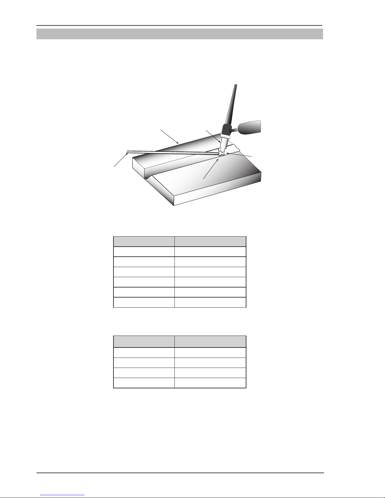
FIREPOWER MST 220i
BASIC WELDING 4-18 Manual 0-5343
4.06 TIG (GTAW) Basic Welding Technique
Gas Tungsten Arc Welding (GTAW) or TIG (Tungsten Inert Gas) as it is commonly referred to, is a welding process
in which fusion is produced by an electric arc that is established between a single tungsten (non-consumable)
electrode and the work piece. Shielding is obtained from a welding grade shielding gas or welding grade shielding
gas mixture which is generally Argon based. A filler metal may also be added manually in some circumstances
depending on the welding application.
Welds Made With or Without
Addition of Filler Metal
Work Piece
Can Be Any Commercial
Metal
Gas Cup
Either Ceramic,
High-lmpact or
Water Cooled
Metal
Inert Gas
Shields Electrode
and Weld Puddle
Tungsten Electrode
Non-Consumable
Art # A-09658_AC
Figure 4-40: TIG (GTAW) Welding Application Shot
Tungsten Electrode Current Ranges
Electrode Diameter DC Current (Amps)
0.040” (1.0mm) 30-60
1/16” (1.6mm) 60-115
3/32” (2.4mm) 100-165
1/8” (3.2mm) 135-200
5/32” (4.0mm) 190-280
3/16” (5mm) 250-340
Table 4-6: Current Ranges for Various Tungsten Electrode Sizes
Guide for Selecting Filler Wire Diameter
Filler Wire Diameter DC Current Range (Amps)
1/16” (1.6mm) 20-90
3/32” (2.4mm) 65-115
1/8” (3.2mm) 100-165
3/16” (5mm) 200-350
Table 4-7: Filler Wire Selection Guide
Page 77

FIREPOWER MST 220i
Manual 0-5343 4-19 BASIC WELDING
Tungsten Electrode Types
Electrode Type
(Ground Finish)
Welding Application Features Color Code
Thoriated 2%
DC welding of mild
steel, stainless steel
and copper
Excellent arc starting,
Long life, High current
carrying capacity
Red
Zirconated 1%
High quality AC welding of aluminum,
magnesium and their
alloys.
Self cleaning, Long
life, Maintains balled
end, High current carrying capacity.
White
Ceriated 2%
AC & DC welding of
mild steel, stainless
steel, copper, aluminum, magnesium and
their alloys
Longer life, More
stable arc, Easier
starting, Wider current
range, Narrower more
concentrated arc.
Grey
Table 4-8
NOTE
The Firepower MST 220i Inverter is not suited for AC TIG welding.
TIG Welding Filler Rods
Base Metal
Thickness
DC Current
for Mild
Steel
DC Current
for Stainless
Steel
Tungsten
Electrode
Diameter
Filler Rod
Diameter (if
required)
Argon Gas
Flow Rate
CFH
Joint Type
0.040”
1.0mm
35-45
40-50
20-30
25-35
0.040”
1.0mm
1/16”
1.6mm
10-15 Butt/Corner
Lap/Fillet
0.045”
1.2mm
45-55
50-60
30-45
35-50
0.040”
1.0mm
1/16”
1.6mm
10-15 Butt/Corner
Lap/Fillet
1/16”
1.6mm
60-70
70-90
40-60
50-70
1/16”
1.6mm
1/16”
1.6mm
15 Butt/Corner
Lap/Fillet
1/8”
3.2mm
80-100
90-115
65-85
90-110
1/16”
1.6mm
3/32”
2.4mm
15 Butt/Corner
Lap/Fillet
3/16”
4.8mm
115-135
140-165
100-125
125-150
3/32”
2.4mm
1/8”
3.2mm
20 Butt/Corner
Lap/Fillet
1/4”
6.4mm
160-175
170-200
135-160
160-180
1/8”
3.2mm
5/32”
4.0mm
20 Butt/Corner
Lap/Fillet
Table 4-9
TIG Welding is generally regarded as a specialized process that requires operator competency. While many of the
principles outlined in the previous Arc Welding section are applicable a comprehensive outline of the TIG Welding
process is outside the scope of this Operating Manual.
Page 78

FIREPOWER MST 220i
BASIC WELDING 4-20 Manual 0-5343
4.07 TIG (GTAW) Welding Problems
FAULT CAUSE REMEDY
1 Excessive bead build up or
poor penetration or poor
fusion at edges of weld.
Welding current is too
low
Increase weld current and/or faulty joint
preparation.
2 Weld bead too wide and
flat or undercut at edges
of weld or excessive burn
through.
Welding current is too
high
Decrease weld current.
3 Weld bead too small or
insufficient penetration or
ripples in bead are widely
spaced apart.
Travel speed too fast Reduce travel speed.
4 Weld bead too wide or
excessive bead build up or
excessive penetration in
butt joint.
Travel speed too slow Increase travel speed.
5 Uneven leg length in fillet
joint
Wrong placement of
filler rod
Re-position filler rod.
6 Electrode melts or oxidizes
when an arc is struck.
A TIG Torch lead connect-
ed to positive welding
terminal.
A Connect TIG Torch lead to negative weld-
ing terminal.
B No gas flowing to weld-
ing region.
B Check the gas lines for kinks or breaks
and gas cylinder contents.
C TIG Torch is clogged
with dust or dirt.
C Clean TIG Torch.
D Gas hose is cut. D Replace gas hose.
E Gas passage contains
impurities.
E Disconnect gas hose from the rear of
Power Source then raise gas pressure
and blow out impurities.
F Gas regulator turned
OFF.
F Turn ON.
G TIG Torch valve is
turned OFF.
G Turn ON.
H The electrode is too
small for the welding
current.
H Increase electrode diameter or reduce the
welding current.
I Power source is set for
MIG welding.
I Set Power Source to LIFT TIG mode.
Page 79

FIREPOWER MST 220i
Manual 0-5343 4-21 BASIC WELDING
FAULT CAUSE REMEDY
7 Dirty weld pool A Electrode contaminated
by contact with work
piece or filler rod material.
A Clean the electrode by grinding off the
contaminates.
B Work piece surface has
foreign material on it.
B Clean surface.
C Gas contaminated with
air.
C Check gas lines for cuts and loose fitting
or change gas cylinder.
8 Poor weld finish Inadequate shielding
gas.
Increase gas flow or check gas line for
gas flow problems.
9 Arc start is not smooth. A Tungsten electrode is
too large for the welding current.
A Select the right size electrode. Refer to
Firepower Electrode Selection Chart.
B The wrong electrode
is being used for the
welding job.
B Select the right electrode type. Refer to
Firepower Electrode Selection Chart.
C Gas flow rate is too
high.
C Select the right rate for the welding job.
Refer to Table 4-9.
D Incorrect shielding gas
is being used.
D Select the right shielding gas.
E Poor work clamp con-
nection to work piece.
E Improve connection to work piece.
10 Arc flutters during TIG
welding.
Tungsten electrode is
too large for the welding current.
Select the right size electrode. Refer to
Firepower Electrode Selection Chart.
11 Tungsten blackens due to
lack of shielding gas
A Gas valve on the TIG
Torch has not been
turned ON.
A Turn ON TIG Torch gas valve before you
commence welding.
B Gas cylinder valve OFF
or TIG Torch hose not
connected to regulator.
B Turn ON gas cylinder valve or connect TIG
Torch hose to regulator.
Table 4-10: TIG (GTAW) Welding Problems
Page 80

FIREPOWER MST 220i
BASIC WELDING 4-22 Manual 0-5343
This Page Intentionally Blank
Page 81

FIREPOWER MST 220i
Manual 0-5343 5-1 PROBLEMS AND ROUTINE SERVICE
SECTION 5: POWER SOURCE PROBLEMS AND ROUTINE SERVICE
REQUIREMENTS
5.01 Power Source Problems
FAULT CAUSE REMEDY
1 Electricity Supply is ON,
power indicator is illuminated however unit will not
commence welding when
the torch trigger switch is
depressed.
A Power source is not in the
correct mode of operation.
A Set the power source to the cor-
rect mode of operation with the
process selection switch.
B Faulty torch trigger. B Repair or replace torch trigger
switch/lead.
2 Fault Indicator is illumi-
nated and unit will not
commence welding when
the torch trigger switch is
depressed.
Duty cycle of power source
has been exceeded.
Leave the power source
switched ON and allow it to cool.
Note that fault indicator must
be extinguished prior to commencement of welding.
3 Unit will not feed wire in
MIG mode.
A Electrode wire stuck in
conduit liner or contact tip
(burn-back jam).
A Check for clogged / kinked MIG
gun conduit liner or worn contact tip. Replace faulty components.
B Internal fault in power
source
B Have an Accredited Firepower
Service Provider investigate the
fault.
4 Welding wire continues to
feed when torch trigger is
released.
A Trigger mode selection
switch is in 4T latch mode.
A Change the trigger mode selec-
tion switch from 4T latch mode
to 2T normal mode.
B Torch trigger leads shorted. B Repair or replace torch trigger
switch/lead.
5 Welding arc cannot be
established in MIG mode.
A MIG gun polarity lead is not
connected into a welding
output terminal.
A Connect the MIG gun polar-
ity lead to either the positive
welding output terminal or the
negative welding output terminal
as required.
B Poor or no work lead
contact.
B Clean work clamp area and en-
sure good electrical contact.
6 Inconsistent wire feed. A Worn or dirty contact tip. A Replace if necessary.
B Worn feed roll. B Replace.
C Excessive brake tension on
wire reel hub.
C Reduce brake tension on spool
hub
D Worn, kinked or dirty con-
duit liner
D Clean or replace conduit liner
7 No gas flow in MIG mode. A Gas hose is damaged. A Replace or repair.
B Gas passage contains
impurities.
B Disconnect gas hose from the
rear of power source and blow
out impurities.
C Gas regulator turned OFF. C Turn ON regulator.
D Empty gas cylinder. D Replace gas cylinder.
Page 82

FIREPOWER MST 220i
PROBLEMS AND ROUTINE SERVICE 5-2 Manual 0-5343
FAULT CAUSE REMEDY
8 Gas flow continues after
the trigger switch has been
released (MIG mode).
Gas valve has jammed open
due to impurities in the gas
or the gas line.
Have an accredited Firepower
service provider repair or replace gas valve.
9 Power indicator will not
illuminate and welding arc
cannot be established.
The Electricity Supply has
exceeded voltage limits of
the power source.
Ensure that the Electricity Supply is within 115V ± 10% or
208/230VAC ± 10%.
10 TIG electrode melts when
arc is struck.
TIG torch is connected to
the (+) VE terminal.
Connect the TIG torch to the (-)
VE terminal.
11 Arc flutters during TIG
welding.
Tungsten electrode is too
large for the welding current.
Select the correct size of tungsten electrode. Refer to Table
4-7.
Table 5-1: Power Source Problems
5.02 Routine Service and Calibration Requirements
WARNING
There are extremely dangerous voltage and power levels present inside this Inverter Power Source.
Do not attempt to open or repair unless you are an accredited Firepower Service Provider. Disconnect
the Welding Power Source from the Electricity Supply before disassembling.
Routine Inspection, Testing & Maintenance
The inspection and testing of the power source and associated accessories shall be carried out by a licensed
electrician. This includes an insulation resistance test and an earthing test to ensure the integrity of the unit is
compliant with Firepower's original specications.
A. Testing Schedule
1. For transportable equipment, at least once every 3 months; and
2. For fixed equipment, at least once every 12 months.
The owners of the equipment shall keep a suitable record of the periodic tests and a system of tagging, including the date of the most recent inspection.
A transportable power source is deemed to be any equipment that is not permanently connected and fixed in
the position in which it is operated.
B. Insulation Resistance
Minimum insulation resistance for in-service Firepower Inverter Power Sources shall be measured at a voltage of 500V between the parts referred to in Table 5-2 below. Power sources that do not meet the insulation
resistance requirements set out below shall be withdrawn from service and not returned until repairs have
been performed such that the requirements outlined below are met.
Page 83

FIREPOWER MST 220i
Manual 0-5343 5-3 PROBLEMS AND ROUTINE SERVICE
Components to be Tested
Minimum Insulation
Resistance (MΩ)
Input circuit (including any connected control circuits) to welding circuit
(including any connected control circuits)
5
All circuits to exposed conductive parts
2.5
Welding circuit (including any connected control circuits) to any auxiliary
circuit which operates at a voltage exceeding extra low voltage
10
Welding circuit (including any connected control circuits) to any auxiliary
circuit which operates at a voltage not exceeding extra low voltage
1
Separate welding circuit to separate welding circuit
1
Table 5-2: Minimum Insulation Resistance Requirements: Firepower Inverter Power Sources
C. Earthing
The resistance shall not exceed 1Ω between any metal of a power source where such metal is required to be
earthed, and -
1. The earth terminal of a fixed power source; or
2. The earth terminal of the associated plug of a transportable power source
Note that due to the dangers of stray output currents damaging fixed wiring, the integrity of fixed wiring supplying Firepower welding power sources should be inspected by a licensed electrical worker in accordance
with the requirements below -
1. For outlets/wiring and associated accessories supplying transportable equipment - at least once every
3 months; and
2. For outlets/wiring and associated accessories supplying fixed equipment - at least once every 12 months.
D. General Maintenance Checks
Welding equipment should be regularly checked by an accredited Firepower Service Provider to ensure that:
1. Flexible cord is of the multi-core tough rubber or plastic sheathed type of adequate rating, correctly
connected and in good condition.
2. Welding terminals are in suitable condition and are shrouded to prevent inadvertent contact or short
circuit.
3. The Welding System is clean internally, especially from metal filing, slag, and loose material.
E. Accessories
Accessory equipment, including output leads, electrode holders, torches, wire feeders and the like shall be
inspected at least monthly by a competent person to ensure that the equipment is in a safe and serviceable
condition. All unsafe accessories shall not be used.
F. Repairs
If any parts are damaged for any reason, it is recommended that replacement be performed by an accredited
Firepower Service Provider.
Page 84

FIREPOWER MST 220i
PROBLEMS AND ROUTINE SERVICE 5-4 Manual 0-5343
Power Source Calibration
A. Schedule
Output testing of all Firepower Inverter Power Sources and applicable accessories shall be conducted at regular
intervals to ensure they fall within specified levels. Calibration intervals shall be as outlined below -
1. For transportable equipment, at least once every 3 months; and
2. For fixed equipment, at least once every 12 months.
B. Calibration Requirements
Where applicable, the tests outlined in Table 5-3 below shall be conducted by an accredited Firepower service
agent.
Testing Requirements
Output current (A) to be checked to ensure it falls within applicable Firepower power source specifications
Output Voltage (V) to be checked to ensure it falls within applicable Firepower power source specifications
Motor Speed (RPM) of wire drive motors to be checked to ensure it falls within required Firepower power
source / wire feeder specifications
Accuracy of digital meters to be checked to ensure it falls within applicable Firepower power source speci-
fications
Table 5-3: Calibration Parameters
Periodic calibration of other parameters such as timing functions are not required unless a specific fault has
been identified.
C. Calibration Equipment
All equipment used for Power Source calibration shall be in proper working condition and be suitable for
conducting the measurement in question. Only test equipment with valid calibration certificates (NATA certified laboratories) shall be utilized.
Page 85
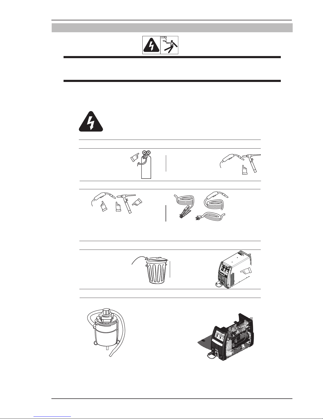
FIREPOWER MST 220i
Manual 0-5343 5-5 PROBLEMS AND ROUTINE SERVICE
5.03 Cleaning the Welding Power Source
WARNING
There are dangerous voltage and power levels present inside this product. Do not attempt to open or
repair unless you are a qualified electrical tradesperson. Disconnect the Welding Power Source from
the Electricity Supply before disassembling.
To clean the Welding Power Source, open the enclosure and use a vacuum cleaner to remove any accumulated
dirt, metal filings, slag and loose material. Keep the shunt and lead screw surfaces clean as accumulated foreign
material may reduce the welders output welding current.
Warning!
Disconnect input power before maintaining.
Each Use
Visual check of
regulator and pressure
Visual check of torch
Consumable parts
Weekly
Visually inspect the torch
body and consumables
Visually inspect the
cables and leads.
Replace as needed
3 Months
Clean
exterior
of power supply
6 Months
Replace all
broken parts
Bring the unit to an authorized
Tweco Service Provider
to remove any accumulated dirt
and dust from the interior.
This may need to be done more
frequently under exceptionally
dirty conditions.
Maintain more often if used under severe conditions
Art # A-10502_AB
Page 86

FIREPOWER MST 220i
PROBLEMS AND ROUTINE SERVICE 5-6 Manual 0-5343
5.04 Cleaning the Feed Rolls
Clean the grooves in the drive rolls frequently. This can be done by using a small wire brush. Also wipe off, or
clean the grooves on the upper feed roll. After cleaning, tighten the feed roll retaining knobs.
CAUTION
Do NOT use compressed air to clean the Welding Power Source. Compressed air can force metal par
ticles to lodge between live electrical parts and earthed metal parts within the Welding Power Source.
This may result in arcing between these parts and their eventual failure.
Page 87

FIREPOWER MST 220i
Manual 0-5343 6-1 REPLACEMENT PARTS
SECTION 6: KEY SPARE PARTS
Torch Part No: 1444-0882
Art# A-12519
5
Figure 6-1
Item
No.
Description Part No.
1
MST Nozzle**
MST Nozzle 3/8"
Bore, Flush
1444-0885
MST Nozzle 1/2"
Bore, Flush
1444-0886
MST Nozzle 5/8"
Bore, Flush
1444-0887
MST Nozzle Flux
Cored
1444-0888
MST Spot
Nozzle, 3/4"
1444-0889
2
MST Contact
Tip**
MST Contact
Tip, .023"
1444-0890
MST Contact
Tip, .030"
1444-0891
MST Contact
Tip, .035"
1444-0892
MST Contact
Tip, .045"
1444-0893
3
Handle / Trigger Repair Kit N/A
4
Universal Conduit Liner*
1444-0883
5
Conductor Tube, Firepower Fusion
140A/180A/220A MIG Gun, 60 Deg
16201108
Table 6-1: Firepower Fusion 220A MIG Gun Parts
** Patent Pending
* Refer to your Firepower Catalog for additional
options.
6.01 Firepower Fusion 220A MIG Gun
Page 88

FIREPOWER MST 220i
REPLACEMENT PARTS 6-2 Manual 0-5343
6.02 Power Source Spare Parts
Art # A-12541
1
2
3
6
7
9
810
11
12
14
13
15
16
18
19
4
5
21
22
23
24
25
17
30
31
29
32
33
34
35
28
Figure 6-2
Page 89

FIREPOWER MST 220i
Manual 0-5343 6-3 REPLACEMENT PARTS
Item Part Number Description
1 W7005621 PCB Power, FP MST220i
2 W7005638 PCB Control, FP MST220i
3 W7005602 PCB Display, FP MST220i
4 W7005607 PCB Spool Gun, FP MST220i
5 W7005603 Wiredrive Assembly, FP MST220i
6 W7004906 Thumbscrew,Feedroll Positioner
7 W4014800 DRIVE RL2 Roll, .023/.035 “V”
8 W7005622 Fan Assembly, FP MST220i UL/CSA
9 W7003010 Rectifier Bridge,1000V,50A
10 W7003033 Gas Solenoid Valve Assy
11 W7003215 Gas Inlet Fitting
12 W7004909 Connector Socket,50 Dinse
13 W7004955 Connector Plug,50 Dinse
14 W7003242 Socket,8 Pin,w/ Harness
15 W7005623 Switch CB,Main On-Off
16 W7004911 CT, Output
17 W7005617 Spool Hub Assembly
18 W7005608 Washer,Friction,Spool Hub
19 W7005609 Spool Hub
20 W7005619 Guide,Inlet,.023-.045 (not shown)
21 W7004967 Guide,Outlet,.023-.045
22 1444-0920 Front, Panel, FP MST220i
23 1444-0921 Panel, Base, FP MST220i
24 1444-0922 Center Panel, FP MST220i
25 1444-0923 Rear, Panel, FP MST220i UL/CSA
26 1444-0924 Panel, Cover, FP MST220i (not shown)
27 1444-0925 Panel, Door, FP MST220i (not shown)
28 1444-0926 Panel,Control,FP MST220i
29 W7004972 Knob,1/4” IDx1” ODx0.9” H
30 W7005630 Knob,1/4” IDx1.25” ODx.9” H
31 W7005629 Circuit Breaker,4A
32 W7004943 Switch,250V/2A
33 870734 Knob,1/4” IDx.72” ODx.9” H
34 W7004940 PCB, Burnback Potentiometer
35 W7005632 Shroud, WF Motor
36 1444-0927 Label, Identification, FP MST220i (not shown)
37 1444-0928 Setup chart, English version, FP MST220i (not shown)
38 1444-0912
Large Spring, for One Pound Spool (not shown)
39 W7005635
Latch, Door, Slide (not shown)
Table 6-2: Firepower MST 220i Parts
Page 90

FIREPOWER MST 220i
REPLACEMENT PARTS 6-4 Manual 0-5343
This Page Intentionally Blank
Page 91

FIREPOWER MST 220i
Manual 0-5343 A-1 APPENDIX
APPENDIX 1: FIREPOWER MST 220i CIRCUIT DIAGRAM
Art # A-11249
ACOUT
DC -
DC +
RED
BLACK
+15V 1
IGBT Driver A 2
IGBT Driver B 3
GND 7
Over Current Signal 6
OT2
Funs
RED
Main Power PCB1
Control PCB2
4 GND
1 +15V
2 -15V
3 Current Feedback
Current Sensor
CONNECTOR LAYOUT DIAGRAM
MWPBFI
FunsDRIVE
ON
1
FAN
PFC CIRCUIT
GUN
MB
BLACK
POS
NEG
+
-
BLACK
WVIN
OT1
DRIVE
IFB
RED
YELLOW
GRAY
WHITE
J5
IN
1
IGBT Driver B 4
IGBT Driver A 5
1 +15V
2 IGBT Driver A
3 IGBT Driver B
7 GND
6 Over Current Signal
4 IGBT Driver B
5 IGBT Driver A
1
1
1
+24VDC 1
-24VDC 3
GND 2
1 +24VDC
2 GND
3 -24VDC
DY2
SOURCE
1
+
1
1
MOTOR PWM CONTROL
CIRCUIT
PWM
PWM
1 PWM RETURN
2 PWM (MOTOR DRIVER 5VDC PEAK)
1
1
1
1
1
ACOUT
SHEETMETAL COVER
60W3
Ω
RX
VR
BR1
BR2
++
+
+ +
+
1
1
1
GAS
SOLENOID
1
1
1
1
1
Wirefeeder
Power
Fault
MIG
LIFT TIG
STICK
2T Normal
4T Latch
Process
Trigger
Wirefeed / Amps
Volts
Down Slope / Arc Force(%)
Arc Control
Amps / Wirefeed Display
Volts Display
12
3456
78
Front View
8A/250V
Fuse
MIG GUN
SPOOL GUN
1
1
K1
L1
L2
GND
OT1
OT2
CR
SOURCE
QF / DY
WVIN
PFC
2
MB
1
POT1
1
CR
JC
QF / DY
GND
+24VDC
3 POT MAX (+5VDC)
2 WIPER
1 POT MIN
RED
BLK
YEL
1 +24VDC
1
1 - OUTPUT
3 + OUTPUT
8 Pin Remote Control
Spool Gun
1
SPOOL GUN (0V) 1
TORCH SWITCH (+24V) 2
TORCH SWITCH RIN (0VDC) 3
SPOOL GUN (+2VDC) 4
TORCH SWITCH RIN (0VDC) 5
TORCH SWITCH RIN (0VDC) 6
(REMOVE VOLTAGE) POT WIPER 7
(REMOVE AMPS/WIRESPEED) POT WIPER 8
1
LOCAL
REMOTE
3 -15VDC
1
1
GUN
+24VDC 1
GND
1
1 +15VDC
1 +15VDC
GND
DISPLAY DATA &EPROM (D-IN) 1
SEIAL DISPLAY DATA (LOAD) 2
SEIAL DISPLAY DATA (CLK) 3
2T/4T PUSHBUTTON 4
SERIAL DISPLAY DATA (EPROM) 5
STICK 6
+15VDC 9
PROCESS PUSHBUTTON 8
POT3 B 11
POT2 WIPER 12
POT3 A (PANEL DEMAND) 13
POT1 WIPER 14
+15VDC 15
GND
J1 J2
J3
J4
J5
J6
J7
J8
J9
J10J11
J12
J13
J1
J2
J3
J4
J5
J6
J7
J8
J9
J10
J11
J12
J13
1
1
RED
WHITE
YELLOW
RED
BLACK
1 +24CDC
GND
+24CDC 1
N/A 2
WHITE
WHITE
WHITE
WHITE
WHITE
WHITE
WHITE
WHITE
WHITE
WHITE
WHITE
WHITE
WHITE
WHITE
WHITE
WHITE
RED
JC
1 +5VDC
2 TO U15 PIN6
INPUT 230V/115V
OUTPUT CONTROL SIGNAL
1
SPOOL GUN PCB3
W7005607
PP
15V
FUSE
SGM
W7005600
W7005601
W7005602
Display PCB4
1
J14
DY1
QF/FJ
J15
J16
J17 J18
J19
J20
J21
J22
J23
J24
J25
J26
9
2J82J72J
J30
MT
J31
J32
J33
J34
J35
75
ć
75
ć
RED
RED
BLACK
BLACK
RED
BLACK
CON3
FJ
BURN BACK PCB 5
W7004940
RED
YELLOW
RED
BLACK
INPUT 115/208/230VAC
50/60Hz50/60Hz50/60Hz
-
-
Page 92

FIREPOWER MST 220i
APPENDIX A-2 Manual 0-5343
This page intentionally blank
Page 93

FIREPOWER - LIMITED WARRANTY TERMS
LIMITED WARRANTY: FIREPOWER ®, Inc, A Victor Technologies Company, warrants to customers of its authorized
distributors hereafter “Purchaser” that its products will be free of defects in workmanship or material. Should any
failure to conform to this warranty appear within the time period applicable to the FIREPOWER products as stated
below, FIREPOWER shall, upon notification thereof and substantiation that the product has been stored, installed,
operated, and maintained in accordance with FIREPOWER’s specifications, instructions, recommendations and
recognized standard industry practice, and not subject to misuse, repair, neglect, alteration, or accident, correct
such defects by suitable repair or replacement, at FIREPOWER’s sole option, of any components or parts of the
product determined by FIREPOWER to be defective.
FIREPOWER MAKES NO OTHER WARRANTY, EXPRESS OR IMPLIED. THIS WARRANTY IS EXCLUSIVE AND IN
LIEU OF ALL OTHERS, INCLUDING, BUT NOT LIMITED TO ANY WARRANTY OF MERCHANTABILITY OR FITNESS
FOR ANY PARTICULAR PURPOSE.
LIMITATION OF LIABILITY: FIREPOWER SHALL NOT UNDER ANY CIRCUMSTANCES BE LIABLE FOR SPECIAL,
INDIRECT OR CONSEQUENTIAL DAMAGES, SUCH AS, BUT NOT LIMITED TO, LOST PROFITS AND BUSINESS
INTERRUPTION. The remedies of the Purchaser set forth herein are exclusive and the liability of FIREPOWER with
respect to any contract, or anything done in connection therewith such as the performance or breach thereof, or
from the manufacture, sale, delivery, resale, or use of any goods covered by or furnished by FIREPOWER whether
arising out of contract, negligence, strict tort, or under any warranty, or otherwise, shall not, except as expressly
provided herein, exceed the price of the goods upon which such liability is based. No employee, agent, or representative of FIREPOWER is authorized to change this warranty in any way or grant any other warranty.
PURCHASER’S RIGHTS UNDER THIS WARRANTY ARE VOID IF REPLACEMENT PARTS OR ACCESSORIES ARE
USED WHICH IN FIREPOWER’S SOLE JUDGMENT MAY IMPAIR THE SAFETY OR PERFORMANCE OF ANY FIREPOWER PRODUCT. PURCHASER’S RIGHTS UNDER THIS WARRANTY ARE VOID IF THE PRODUCT IS SOLD TO
PURCHASER BY NON-AUTHORIZED PERSONS.
The warranty is effective for the time stated below beginning on the date that the authorized distributor delivers
the products to the Purchaser. Notwithstanding the foregoing, in no event shall the warranty period extend more
than the time stated plus one year from the date FIREPOWER delivered the product to the authorized distributor.
Page 94

This page intentionally blank
Page 95

WARRANTY SCHEDULE
2 Years Parts* and Labor
* 2 years on the Original Main Power Transformer and Inductors not mounted on PC Boards.
* 2 years on Power Supply Components
2 Years Parts / No Labor
Auto-Darkening Welding Helmet (electronic Lens), ** 1 Month Harness Assy
Firepower Regulator for Firepower MST 220i (No labor)
90 days parts / No Labor
Remote Controls
MIG and TIG Torches (Supplied with power sources)
Replacement repair parts
Victor Technologies limited warranty shall not apply to:
Consumable Parts for MIG, TIG, Plasma welding, Plasma cutting and Oxy fuel torches, O-rings, fuses, filters or other parts that fail due
normal wear
* Warranty repairs or replacement claims under this limited warranty must be submitted by an authorized Victor Technologies repair
facility within thirty (30) days of the repair.
* No employee, agent, or representative of Victor Technologies is authorized to change this warranty in any way or grant any other
warranty, and Victor Technologies shall not be bound by any such attempt. Correction of non-conformities, in the manner and time
provided herein, constitutes fulfillment of Victor Technologies’s obligations to purchaser with respect to the product.
* This warranty is void, and seller bears no liability hereunder, if purchaser used replacement parts or accessories which, in Victor
Technologies's sole judgment, impaired the safety or performance of any Victor Technologies product. Purchaser’s rights under this
warranty are void if the product is sold to purchaser by unauthorized persons.
Page 96

© 2014 Victor Technologies International, Inc. www.victortechnologies.com Printed in China
THE AMERICAS
Denton, TX USA
U.S. Customer Care
Ph 1-800-426-1888 (tollfree)
Fax: 1-800-535-0557 (tollfree)
International Customer Care
Ph 1-940-381-1212
Fax: 1-940-483-8178
Miami, FL USA
Sales Office, Latin America
Ph 1-954-727-8371
Fax: 1-954-727-8376
Oakville, Ontario, Canada
Canada Customer Care
Ph 1-905-827-4515
Fax: 1-800-588-1714 (tollfree)
EUROPE
Chorley, United Kingdom
Customer Care
Ph +44 1257-261755
Fax: +44 1257-224800
Milan, Italy
Customer Care
Ph +39 0236546801
Fax: +39 0236546840
ASIA/PACIFIC
Cikarang, Indonesia
Customer Care
Ph 6221-8990-6095
Fax: 6221-8990-6096
Rawang, Malaysia
Customer Care
Ph +603 6092-2988
Fax: +603 6092-1085
Melbourne, Australia
Australia Customer Care
Ph 1300-654-674 (tollfree)
Ph 61-3-9474-7400
Fax: 61-3-9474-7391
International
Ph 61-3-9474-7508
Fax: 61-3-9474-7488
Shanghai, China
Sales Office
Ph +86 21-64072626
Fax: +86 21-64483032
Singapore
Sales Office
Ph +65 6832-8066
Fax: +65 6763-5812
U.S. Customer Care: 800-426-1888 / FAX 800-535-0557
Canada Customer Care: 905-827-4515 / FAX 800-588-1714
International Customer Care: 940-381-1212 / FAX 940-483-8178
INNOVATION TO SHAPE THE WORLD™
T ECHNOLOGIES
™
 Loading...