

Page 1
Plasma Cutting
Power Supply
Firepower FP-82
A-02990
Service Manual
December 4, 2002 Manual No. 0-2871
Page 2

Page 3

WARNINGS
Read and understand this entire Manual and your employer’s safety practices before installing, operating, or servicing the equipment.
While the information contained in this Manual represents the Manufacturer's best judgement, the
Manufacturer assumes no liability for its use.
Plasma Cutting Power Supply
Firepower FP-82
Service Manual Number 0-2871
www.firepoweronline.com
Published by:
Thermal Dynamics Corporation
82 Benning Street
West Lebanon, New Hampshire, USA 03784
(603) 298-5711
Copyright 2002 by
Thermal Dynamics Corporation
All rights reserved.
Reproduction of this work, in whole or in part, without written permission of the publisher is prohibited.
The publisher does not assume and hereby disclaims any liability to
any party for any loss or damage caused by any error or omission in
this Manual, whether such error results from negligence, accident, or
any other cause.
Printed in the United States of America
Publication Date: December 4, 2002
Record the following information for Warranty purposes:
Where Purchased:____________________________________
Purchase Date:_______________________________________
Power Supply Serial #:________________________________
Torch Serial #:________________________________________
Page 4

TABLE OF CONTENTS
SECTION 1:
GENERAL INFORMATION ............................................................................................... 1-1
1.01 Notes, Cautions and Warnings..................................................................... 1-1
1.02 Important Safety Precautions ....................................................................... 1-1
1.03 Publications.................................................................................................. 1-2
1.04 Note, Attention et Avertissement .................................................................. 1-3
1.05 Precautions De Securite Importantes........................................................... 1-3
1.06 Documents De Reference............................................................................ 1-5
1.07 Declaration of Conformity............................................................................. 1-7
1.08 Statement of W arranty.................................................................................. 1-8
SECTION 2:
INTRODUCTION .............................................................................................................. 2-1
2.01 Scope Of Manual ......................................................................................... 2-1
2.02 General Service Philosophy ......................................................................... 2-1
2.03 Service Responsibilities ............................................................................... 2-1
SECTION 3:
DESCRIPTION ................................................................................................................. 3-1
3.01 Scope........................................................................................................... 3-1
3.02 General Description ..................................................................................... 3-1
3.03 Specifications/Design Features.................................................................... 3-1
3.04 P ow er Supply Options and Accessories....................................................... 3-2
SECTION 4:
SERVICE TR OUBLESHOOTING DIAGNOSTICS ............................................................ 4-1
4.01 Introduction .................................................................................................. 4-1
4.02 P eriodic Inspection & Cleaning Procedures.................................................. 4-1
4.03 System Theory ............................................................................................. 4-1
4.04 Common Operating Problems...................................................................... 4-2
4.05 Troubleshooting Guide - General Information ............................................... 4-3
4.06 Circuit Fault Isolation .................................................................................... 4-4
4.07 Main Input and Internal Po wer Prob lems...................................................... 4-5
4.08 Pilot Arc Problems........................................................................................ 4-8
4.09 Main Arc Problems..................................................................................... 4-10
4.10 Test Procedures ......................................................................................... 4-10
SECTION 5:
REPAIRS & REPLACEMENT PROCEDURES.................................................................. 5-1
5.01 Scope........................................................................................................... 5-1
5.02 Anti-Static Handling Procedures................................................................... 5-1
5.03 Parts Replacement - General Inf ormation .................................................... 5-1
5.04 Major External Parts Replacement............................................................... 5-2
5.05 Front Panel Parts Replacement.................................................................... 5-3
5.06 Left Side Internal Component Parts Replacement........................................ 5-4
5.07 Rear Panel P arts Replacement .................................................................... 5-6
5.08 Right Side Internal Component Parts Replacement ..................................... 5-9
Page 5

TABLE OF CONTENTS (continued)
SECTION 6:
PARTS LISTS.................................................................................................................... 6-1
6.01 Introduction .................................................................................................. 6-1
6.02 Ordering Information .................................................................................... 6-1
6.03 Major External Replacement Parts............................................................... 6-2
6.04 Front Panel Replacement Parts.................................................................... 6-3
6.05 Left Side Internal Replacement Parts........................................................... 6-4
6.06 Rear Panel Replacement P arts .................................................................... 6-5
6.07 Right Side Internal Replacement Parts ........................................................ 6-6
6.08 Options and Accessories ............................................................................. 6-8
APPENDIX 1: INPUT WIRING REQ UIREMENTS ....................................................................A-1
APPENDIX 2: SEQUENCE OF OPERATION (BLOCK DIA GRAM) ..........................................A-2
APPENDIX 3: LOGIC PC BO ARD LAYOUT .............................................................................A-3
APPENDIX 4: MAIN PO WER PC BOARD LAYOUT ................................................................. A-4
APPENDIX 5: MAIN PC BO ARD WIRING .................................................................................A-6
APPENDIX 6: CD PC BOARD LAYOUT ...................................................................................A-7
APPENDIX 7: LED/POT PC BOARD LA YOUT..........................................................................A-8
APPENDIX 8: IGBT CIRCUIT PC BO ARD LAYOUT ................................................................. A-9
APPENDIX 9: INPUT DIODE PC BO ARD LAYOUT................................................................A-10
APPENDIX 10: OUTPUT DIODE PC BO ARD LAYOUT ..........................................................A-11
APPENDIX 11: PO WER OUTPUT PCB WIRING DIAGRAM................................................... A-12
APPENDIX 12: 28VAC CIRCUIT DIAGRAM........................................................................... A-13
APPENDIX 13: MAINTENANCE SCHEDULE ........................................................................ A-14
APPENDIX 14: SYSTEM SCHEMATIC...................................................................................A-16
Page 6

Page 7

SECTION 1:
GENERAL INFORMATION
1.01 Notes, Cautions and Warnings
Throughout this manual, notes, cautions, and warnings
are used to highlight important information. These highlights are categorized as follows:
NOTE
An operation, procedure, or backgr ound information which requires additional emphasis or is helpful in efficient operation of the system.
CAUTION
A procedure which, if not properly followed, may
cause damage to the equipment.
WARNING
A procedure which, if not properly followed, may
cause injury to the operator or others in the operating area.
1.02 Important Safety Precautions
WARNINGS
OPERATION AND MAINTENANCE OF
PLASMA ARC EQUIPMENT CAN BE DANGEROUS AND HAZARDOUS TO YOUR
HEAL TH.
Plasma arc cutting produces intense electric and
magnetic emissions that may interfere with the
proper function of cardiac pacemakers, hearing
aids, or other electronic health equipment. Persons who work near plasma arc cutting applications should consult their medical health professional and the manufacturer of the health
equipment to determine whether a hazard exists.
To prevent possible injury, read, understand and
follow all warnings, safety precautions and instructions before using the equipment. Call 1-603298-5711 or your local distributor if you have any
questions.
GASES AND FUMES
Gases and fumes produced during the plasma cutting
process can be dangerous and hazardous to your health.
• Keep all fumes and gases from the breathing area.
Keep your head out of the welding fume plume.
• Use an air-supplied respirator if ventilation is not
adequate to remove all fumes and gases.
• The kinds of fumes and gases from the plasma arc
depend on the kind of metal being used, coatings
on the metal, and the different pr ocesses. Y ou must
be very careful when cutting or welding any metals which may contain one or more of the following:
Antimony Chromium Mercury
Arsenic Cobalt Nickel
Barium Copper Selenium
Beryllium Lead Silver
Cadmium Manganese Vanadium
• Always read the Material Safety Data Sheets
(MSDS) that should be supplied with the material
you are using. These MSDSs will give you the information regarding the kind and amount of fumes
and gases that may be dangerous to your health.
• For information on how to test for fumes and gases
in your workplace, refer to item 1 in Subsection 1.03,
Publications in this manual.
• Use special equipment, such as water or down draft
cutting tables, to capture fumes and gases.
• Do not use the plasma torch in an area where combustible or explosive gases or materials are located.
• Phosgene, a toxic gas, is generated from the vapors
of chlorinated solvents and cleansers. Remove all
sources of these vapors.
• This product, when used for welding or cutting,
produces fumes or gases which contain chemicals
known to the State of California to cause birth defects and, in some cases, cancer . (California Health
& Safety Code Sec. 25249.5 et seq.)
ELECTRIC SHOCK
Electric Shock can injure or kill. The plasma arc process
uses and produces high voltage electrical energy. This
electric energy can cause severe or fatal shock to the operator or others in the workplace.
• Never touch any parts that are electrically “live”
or “hot.”
Date: No v ember 15, 2001 1-1 GENERAL INFORMATION
Page 8
• Wear dry gloves and clothing. Insulate yourself
from the work piece or other parts of the welding
circuit.
• Repair or replace all worn or damaged parts.
• Extra care must be taken when the workplace is
moist or damp.
• Install and maintain equipment according to NEC
code, refer to item 9 in Subsection 1.03, Publications.
• Disconnect power source before performing any
service or repairs.
• Read and follow all the instructions in the Operating Manual.
FIRE AND EXPLOSION
Fire and explosion can be caused by hot slag, sparks, or
the plasma arc.
• Be sure there is no combustible or flammable material in the workplace. Any material that cannot
be removed must be protected.
• Ventilate all flammable or explosive vapors from
the workplace.
• Do not cut or weld on containers that may have
held combustibles.
• Provide a fire watch when working in an area where
fire hazards may exist.
• Hydrogen gas may be formed and trapped under
aluminum workpieces when they are cut underwater or while using a water table. DO NOT cut
aluminum alloys underwater or on a water table
unless the hydrogen gas can be eliminated or dissipated. T rapped hydrogen gas that is ignited will
cause an explosion.
NOISE
Noise can cause permanent hearing loss. Plasma arc processes can cause noise levels to exceed safe limits. You
must protect your ears from loud noise to prevent permanent loss of hearing.
• T o protect your hearing from loud noise, wear pr otective ear plugs and/or ear muffs. Protect others
in the workplace.
• Noise levels should be measured to be sure the decibels (sound) do not exceed safe levels.
• For information on how to test for noise, see item 1
in Subsection 1.03, Publications, in this manual.
PLASMA ARC RA YS
Plasma Arc Rays can injure your eyes and burn your skin.
The plasma arc process produces very bright ultra violet
and infra red light. These arc rays will damage your
eyes and burn your skin if you are not properly pr otected.
• To protect your eyes, always wear a welding helmet or shield. Also always wear safety glasses with
side shields, goggles or other protective eye wear.
• Wear welding gloves and suitable clothing to protect your skin from the arc rays and sparks.
• Keep helmet and safety glasses in good condition.
Replace lenses when cracked, chipped or dirty.
• Protect others in the work area from the arc rays.
Use protective booths, screens or shields.
• Use the shade of lens as suggested in the following
per ANSI/ASC Z49.1:
Minimum Protective Suggested
Arc Current Shade No. Shade No.
Less Than 300* 8 9
300 - 400* 9 12
400 - 800* 10 14
* These values apply where the actual arc is clearly
seen. Experience has shown that lighter filters
may be used when the arc is hidden by the workpiece.
1.03 Publications
Refer to the following standards or their latest revisions
for more information:
1. OSHA, SAFETY AND HEAL TH STANDARDS, 29CFR
1910, obtainable from the Superintendent of Documents, U.S. Government Printing Office, Washington,
D.C. 20402
2. ANSI Standard Z49.1, SAFETY IN WELDING AND
CUTTING, obtainable from the American Welding Society, 550 N.W. LeJeune Rd, Miami, FL 33126
3. NIOSH, SAFETY AND HEALTH IN ARC WELDING
AND GAS WELDING AND CUTTING, obtainable
from the Superintendent of Documents, U.S. Government Printing Office, Washington, D.C. 20402
4. ANSI Standard Z87.1, SAFE PRACTICES FOR OCCUP ATION AND EDUCA TIONAL EYE AND F ACE PROTECTION, obtainable from American National Standards Institute, 1430 Broadway, New York, NY 10018
5. ANSI Standard Z41.1, STANDARD FOR MEN’S
SAFETY -TOE FOOTWEAR, obtainable from the American National Standards Institute, 1430 Broadway, New
York, NY 10018
GENERAL INFORMATION 1-2 Date: Nov ember 15, 2001
Page 9
6. ANSI Standard Z49.2, FIRE PREVENTION IN THE USE
OF CUTTING AND WELDING PROCESSES, obtainable from American National Standards Institute, 1430
Broadway, New York, NY 10018
7. AWS Standar d A6.0, WELDING AND CUTTING CONTAINERS WHICH HAVE HELD COMBUSTIBLES, obtainable from American Welding Society, 550 N.W.
LeJeune Rd, Miami, FL 33126
8. NFPA Standard 51, OXYGEN-FUEL GAS SYSTEMS
FOR WELDING, CUTTING AND ALLIED PROCESSES, obtainable from the National Fire Protection
Association, Batterymarch Park, Quincy, MA 02269
9. NFPA Standard 70, NATIONAL ELECTRICAL CODE,
obtainable from the National Fire Protection Association, Batterymarch Park, Quincy, MA 02269
10. NFP A Standard 51B, CUTTING AND WELDING PROCESSES, obtainable from the National Fire Protection
Association, Batterymarch Park, Quincy, MA 02269
11. CGA Pamphlet P-1, SAFE HANDLING OF COMPRESSED GASES IN CYLINDERS, obtainable from the
Compressed Gas Association, 1235 Jefferson Davis
Highway, Suite 501, Arlington, VA 22202
12. CSA Standard W1 17.2, CODE FOR SAFETY IN WELDING AND CUTTING, obtainable from the Canadian
Standards Association, Standards Sales, 178 Rexdale
Boulevard, Rexdale, Ontario, Canada M9W 1R3
13. NWSA booklet, WELDING SAFETY BIBLIOGRAPHY
obtainable from the National Welding Supply Association, 1900 Arch Street, Philadelphia, PA 19103
14. American W elding Society Standard A WSF4.1, RECOMMENDED SAFE PRACTICES FOR THE PREPARATION FOR WELDING AND CUTTING OF CONT AINERS AND PIPING THAT HAVE HELD HAZARDOUS
SUBSTANCES, obtainable fr om the American Welding
Society, 550 N.W. LeJeune Rd, Miami, FL 33126
ATTENTION
Toute procédure pouvant résulter
l’endommagement du matériel en cas de nonrespect de la procédur e en question.
AVERTISSEMENT
Toute procédure pouvant provoquer des blessures
de l’opérateur ou des autres personnes se trouvant
dans la zone de travail en cas de non-respect de la
procédure en question.
1.05 Precautions De Securite Importantes
AVERTISSEMENTS
L’OPÉRATION ET LA MAINTENANCE DU
MATÉRIEL DE SOUDAGE À L’ARC AU JET
DE PLASMA PEUVENT PRÉSENTER DES
RISQUES ET DES DANGERS DE SANTÉ.
Coupant à l’arc au jet de plasma produit de l’énergie
électrique haute tension et des émissions
magnétique qui peuvent interférer la fonction
propre d’un “pacemaker” cardiaque, les appareils
auditif, ou autre matériel de santé electronique.
Ceux qui travail près d’une application à l’arc au
jet de plasma devrait consulter leur membre
professionel de médication et le manufacturier de
matériel de santé pour déterminer s’il existe des
risques de santé.
15. ANSI Standard Z88.2, PRACTICE FOR RESPIRA TOR Y
PROTECTION, obtainable from American National
Standards Institute, 1430 Broadway, New York, NY
10018
1.04 Note, Attention et
Avertissement
Dans ce manuel, les mots “note,” “attention,” et
“avertissement” sont utilisés pour mettre en relief des
informations à caractère important. Ces mises en relief
sont classifiées comme suit :
NOTE
Toute opération, procédure ou renseignement
général sur lequel il importe d’insister davantage
ou qui contribue à l’efficacité de fonctionnement
du système.
Date: No v ember 15, 2001 1-3 GENERAL INFORMATION
Il faut communiquer aux opérateurs et au personnel TOUS les dangers possibles. Afin d’éviter les
blessures possibles, lisez, comprenez et suivez tous
les avertissements, toutes les précautions de sécurité
et toutes les consignes avant d’utiliser le matériel.
Composez le + 603-298-5711 ou votr e distributeur
local si vous avez des questions.
FUMÉE et GAZ
La fumée et les gaz produits par le procédé de jet de
plasma peuvent présenter des risques et des dangers de
santé.
Page 10
• Eloignez toute fumée et gaz de votre zone de respiration. Gardez votre tête hors de la plume de fumée
provenant du chalumeau.
• Utilisez un appareil respiratoire à alimentation en air
si l’aération fournie ne permet pas d’éliminer la fumée
et les gaz.
• Ne touchez jamais une pièce “sous tension” ou “vive”;
portez des gants et des vêtements secs. Isolez-vous
de la pièce de travail ou des autres parties du circuit
de soudage.
• Réparez ou remplacez toute pièce usée ou
endommagée.
• Les sortes de gaz et de fumée provenant de l’arc de
plasma dépendent du genre de métal utilisé, des
revêtements se trouvant sur le métal et des différ ents
procédés. Vous devez prendre soin lorsque vous
coupez ou soudez tout métal pouvant contenir un ou
plusieurs des éléments suivants:
antimoine cadmium mercure
argent chrome nickel
arsenic cobalt plomb
baryum cuivre sélénium
béryllium manganèse vanadium
• Lisez toujours les fiches de données sur la sécurité
des matières (sigle américain “MSDS”); celles-ci
devraient être fournies avec le matériel que vous
utilisez. Les MSDS contiennent des renseignements
quant à la quantité et la nature de la fumée et des gaz
pouvant poser des dangers de santé.
• Pour des informations sur la manière de tester la
fumée et les gaz de votre lieu de travail, consultez
l’article 1 et les documents cités à la page 5.
• Utilisez un équipement spécial tel que des tables de
coupe à débit d’eau ou à courant descendant pour
capter la fumée et les gaz.
• N’utilisez pas le chalumeau au jet de plasma dans une
zone où se trouvent des matières ou des gaz combustibles ou explosifs.
• Le phosgène, un gaz toxique, est généré par la fumée
provenant des solvants et des produits de nettoyage
chlorés. Eliminez toute source de telle fumée.
• Ce produit, dans le procéder de soudage et de coupe,
produit de la fumée ou des gaz pouvant contenir des
éléments reconnu dans L’état de la Californie, qui
peuvent causer des défauts de naissance et le cancer .
(La sécurité de santé en Californie et la code sécurité
Sec. 25249.5 et seq.)
CHOC ELECTRIQUE
• Prenez des soins particuliers lorsque la zone de travail est humide ou moite.
• Montez et maintenez le matériel conformément au
Code électrique national des Etats-Unis. (V oir la page
5, article 9.)
• Débranchez l’alimentation électrique avant tout travail d’entretien ou de réparation.
• Lisez et respectez toutes les consignes du Manuel de
consignes.
INCENDIE ET EXPLOSION
Les incendies et les explosions peuvent résulter des scories
chaudes, des étincelles ou de l’arc de plasma. Le procédé
à l’arc de plasma produit du métal, des étincelles, des
scories chaudes pouvant mettre le feu aux matières combustibles ou provoquer l’explosion de fumées
inflammables.
• Soyez certain qu’aucune matière combustible ou inflammable ne se trouve sur le lieu de travail. Protégez
toute telle matière qu’il est impossible de retirer de la
zone de travail.
• Procurez une bonne aération de toutes les fumées
inflammables ou explosives.
• Ne coupez pas et ne soudez pas les conteneurs ayant
pu renfermer des matières combustibles.
• Prévoyez une veille d’incendie lors de tout travail dans
une zone présentant des dangers d’incendie.
• Le gas hydrogène peut se former ou s’accumuler sous
les pièces de travail en aluminium lorsqu’elles sont
coupées sous l’eau ou sur une table d’eau. NE PAS
couper les alliages en aluminium sous l’eau ou sur
une table d’eau à moins que le gas hydrogène peut
s’échapper ou se dissiper . Le gas hydrogène accumulé
explosera si enflammé.
Les chocs électriques peuvent blesser ou même tuer. Le
procédé au jet de plasma requiert et produit de l’éner gie
électrique haute tension. Cette énergie électrique peut
produire des chocs graves, voire mortels, pour l’opérateur
et les autres personnes sur le lieu de travail.
GENERAL INFORMATION 1-4 Date: Nov ember 15, 2001
Les rayons provenant de l’arc de plasma peuvent blesser
vos yeux et brûler votre peau. Le procédé à l’arc de
plasma produit une lumière infra-rouge et des rayons
RAYONS D’ARC DE PLASMA
Page 11

ultra-violets très forts. Ces rayons d’arc nuiront à vos
yeux et brûleront votre peau si vous ne vous protégez
pas correctement.
• Pour protéger vos yeux, portez toujours un casque ou
un écran de soudeur . Portez toujours des lunettes de
sécurité munies de parois latérales ou des lunettes de
protection ou une autre sorte de protection oculair e.
• Portez des gants de soudeur et un vêtement protecteur
approprié pour protéger votre peau contre les
étincelles et les rayons de l’arc.
• Maintenez votre casque et vos lunettes de protection
en bon état. Remplacez toute lentille sale ou
comportant fissure ou rognure.
• Protégez les autres personnes se trouvant sur la zone
de travail contre les rayons de l’arc en fournissant des
cabines ou des écrans de protection.
• Utilisez la nuance de lentille qui est suggèrée dans le
recommendation qui suivent ANSI/ASC Z49.1:
Nuance Minimum Nuance Suggerée
Courant Arc Protective Numéro Numéro
Moins de 300* 8 9
300 - 400* 9 12
400 - 800* 10 14
* Ces valeurs s’appliquent ou l’arc actuel est observé
clairement. L ’experience a démontrer que les filtres
moins foncés peuvent être utilisés quand l’arc est
caché par moiceau de travail.
1.06 Documents De Reference
Consultez les normes suivantes ou les révisions les plus
récentes ayant été faites à celles-ci pour de plus amples
renseignements :
1. OSHA, NORMES DE SÉCURITÉ DU TRA VAIL ET DE
PROTECTION DE LA SANTÉ, 29CFR 1910,
disponible auprès du Superintendent of Documents,
U.S. Government Printing Office, Washington, D.C.
20402
2. Norme ANSI Z49.1, LA SÉCURITÉ DES
OPÉRATIONS DE COUPE ET DE SOUDAGE,
disponible auprès de la Société Américaine de
Soudage (American Welding Society), 550 N.W.
LeJeune Rd., Miami, FL 33126
3. NIOSH, LA SÉCURITÉ ET LA SANTÉ LORS DES
OPÉRATIONS DE COUPE ET DE SOUDAGE À
L’ARC ET AU GAZ, disponible auprès du Superintendent of Documents, U.S. Government Printing
Office, Washington, D.C. 20402
4. Norme ANSI Z87.1, PRATIQUES SURES POUR LA
PROTECTION DES YEUX ET DU VISAGE AU TRAV AIL ET DANS LES ECOLES, disponible de l’Institut
Américain des Normes Nationales (American National Standards Institute), 1430 Broadway, New Y ork,
NY 10018
5. Norme ANSI Z41.1, NORMES POUR LES
CHAUSSURES PROTECTRICES, disponible auprès
de l’American National Standards Institute, 1430
Broadway, New York, NY 10018
BRUIT
Le bruit peut provoquer une perte permanente de l’ouïe.
Les procédés de soudage à l’arc de plasma peuvent
provoquer des niveaux sonores supérieurs aux limites
normalement acceptables. V ous dú4ez vous pr otéger les
oreilles contre les bruits forts afin d’éviter une perte
permanente de l’ouïe.
• Pour protéger votre ouïe contre les bruits forts, portez
des tampons protecteurs et/ou des protections
auriculaires. Protégez également les autres personnes
se trouvant sur le lieu de travail.
• Il faut mesurer les niveaux sonores afin d’assurer que
les décibels (le bruit) ne dépassent pas les niveaux
sûrs.
• Pour des renseignements sur la manière de tester le
bruit, consultez l’article 1, page 5.
6. Norme ANSI Z49.2, PRÉVENTION DES INCENDIES
LORS DE L ’EMPLOI DE PROCÉDÉS DE COUPE ET
DE SOUDAGE, disponible auprès de l’American National Standards Institute, 1430 Broadway, New Y ork,
NY 10018
7. Norme A6.0 de l’Association Américaine du Soudage
(AWS), LE SOUDAGE ET LA COUPE DE
CONTENEURS A YANT RENFERMÉ DES PRODUITS
COMBUSTIBLES, disponible auprès de la American
Welding Society, 550 N.W. LeJeune Rd., Miami, FL
33126
8. Norme 51 de l’Association Américaine pour la Protection contre les Incendies (NFPA), LES SYSTEMES
À GAZ AVEC ALIMENTATION EN OXYGENE
POUR LE SOUDAGE, LA COUPE ET LES
PROCÉDÉS ASSOCIÉS, disponible auprès de la National Fire Protection Association, Batterymar ch Park,
Quincy, MA 02269
Date: No v ember 15, 2001 1-5 GENERAL INFORMATION
Page 12

9. Norme 70 de la NFPA, CODE ELECTRIQUE NATIONAL, disponible auprès de la National Fire Protection Association, Batterymarch Park, Quincy, MA
02269
10. Norme 51B de la NFPA, LES PROCÉDÉS DE
COUPE ET DE SOUDAGE, disponible auprès de la
National Fire Protection Association, Batterymarch
Park, Quincy, MA 02269
11. Brochure GCA P-1, LA MANIPULATION SANS
RISQUE DES GAZ COMPRIMÉS EN CYLINDRES,
disponible auprès de l’Association des Gaz
Comprimés (Compressed Gas Association), 1235
Jefferson Davis Highway, Suite 501, Arlington, VA
22202
12. Norme CSA W117.2, CODE DE SÉCURITÉ POUR
LE SOUDAGE ET LA COUPE, disponible auprès
de l’Association des Normes Canadiennes, Standards Sales, 178 Rexdale Boulevard, Rexdale,
Ontario, Canada, M9W 1R3
13. Livret NWSA, BIBLIOGRAPHIE SUR LA
SÉCURITÉ DU SOUDAGE, disponible auprès de
l’Association Nationale de Fournitures de Soudage
(National Welding Supply Association), 1900 Arch
Street, Philadelphia, PA 19103
14. Norme AWSF4.1 de l’Association Américaine de
Soudage, RECOMMANDATIONS DE PRATIQUES
SURES POUR LA PRÉPARA TION À LA COUPE ET
AU SOUDAGE DE CONTENEURS ET TUYAUX
AYANT RENFERMÉ DES PRODUITS
DANGEREUX , disponible auprès de la American
Welding Society, 550 N.W. LeJeune Rd., Miami, FL
33126
15. Norme ANSI Z88.2, PRATIQUES DE PROTECTION
RESPIRATOIRE, disponible auprès de l’American
National Standards Institute, 1430 Broadway, New
York, NY 10018
GENERAL INFORMATION 1-6 Date: Nov ember 15, 2001
Page 13

1.07 Declaration of Conformity
Manufacturer: Thermal Dynamics Corporation
Address: 82 Benning Street
W est Lebanon, New Hampshire 03784
USA
The equipment described in this manual conforms to all applicable aspects and regulations of the ‘Low Voltage Directive’
(European Council Directive 73/23/EEC as amended by Council Directive 93/68/EEC) and to the National legislation for
the enforcement of this Directive.
Serial numbers are unique with each individual piece of equipment and details description, parts used to manufacture a unit
and date of manufacture.
National Standard and Technical Specifications
The product is designed and manufactured to a number of standards and technical requir ements. Among them are:
* CSA (Canadian Standards Association) standard C22.2 number 60 for Arc welding equipment.
* UL (Underwriters Laboratory) rating 94VO flammability testing for all printed-circuit boar ds used.
* ISO/IEC 60974-1 (BS 638-PT10) (EN 60 974-1) (EN50192) (EN50078) applicable to plasma cutting equipment and associ-
ated accessories.
* Extensive product design verification is conducted at the manufacturing facility as part of the routine design and manufac-
turing process. This is to ensure the product is safe, when used according to instructions in this manual and related
industry standards, and performs as specified. Rigorous testing is incorporated into the manufacturing process to ensure
the manufactured product meets or exceeds all design specifications.
Thermal Dynamics has been manufacturing products for more than 30 years, and will continue to achieve excellence in our
area of manufacture.
Manufacturers responsible representative: Giorgio Bassi
Managing Director
Thermal Dynamics Europe
Via rio Fabbiani 8A
40067 Rastignano (BO)
Italy
Date: No v ember 15, 2001 1-7 GENERAL INFORMATION
Page 14

1.08 Statement of Warranty
LIMITED WARRANTY: Firepower® (hereinafter “Firepower”) warrants that its products will be free of defects in workmanship or
material. Should any failure to conform to this warranty appear within the time period applicable to the Firepower products as stated
below , Firepower shall, upon notification thereof and substantiation that the pr oduct has been stored, installed, operated, and maintained
in accordance with Firepower’s specifications, instructions, recommendations and recognized standard industry practice, and not subject
to misuse, repair, neglect, alteration, or accident, correct such defects by suitable repair or replacement, at Firepower’s sole option, of
any components or parts of the product determined by Firepowerto be defective.
THIS WARRANTY IS EXCLUSIVE AND IS IN LIEU OF ANY WARRANTY OF MERCHANTABILITY OR FITNESS FOR A
PAR TICULAR PURPOSE.
LIMIT ATION OF LIABILITY: Firepower shall not under any circumstances be liable for special or consequential damages, such as, but
not limited to, damage or loss of purchased or replacement goods, or claims of customers of distributor (hereinafter “Purchaser”) for
service interruption. The remedies of the Purchaser set forth herein are exclusive and the liability of Firepower with respect to any
contract, or anything done in connection therewith such as the performance or breach thereof, or from the manufacture, sale, delivery,
resale, or use of any goods covered by or furnished by Firepower whether arising out of contract, negligence, strict tort, or under any
warranty, or otherwise, shall not, except as expressly provided herein, exceed the price of the goods upon which such liability is based.
THIS WARRANTY BECOMES INVALID IF REPLACEMENT PARTS OR ACCESSORIES ARE USED WHICH MAY IMPAIR THE
SAFETY OR PERFORMANCE OF ANY FIREPOWER PRODUCT.
THIS WARRANTY IS INVALID IF THE PRODUCT IS SOLD BY NON-AUTHORIZED PERSONS.
The limited warranty periods for Firepower products shall be as follows: A maximum of four (4) years fr om date of sale to an authorized
distributor and a maximum of three (3) years from date of sale by such distributor to the Purchaser, and with the following further
limitations on such three (3) year period.
POWER SUPPLIES PA R TS LABOR
MAIN POWER MAGNETICS ......................................................................................................3 YEARS ................... 1 YEAR
ORIGINAL MAIN POWER RECTIFIER ..................................................................................... 3 YEARS ................... 1 YEAR
CONTROL PC BOARD .................................................................................................................. 3 YEARS ................... 1 YEAR
ALL OTHER CIRCUITS AND COMPONENTS......................................................................... 1 YEAR ....................1 YEAR
INCLUDING, BUT NOT LIMITED TO, STARTING
CIRCUIT, CONTACTORS, RELAYS, SOLENOIDS, PUMPS,
POWER SWITCHING SEMI-CONDUCTORS
CONSOLES, CONTROL EQUIPMENT, HEAT ............................................................................. 1 YEAR .................. 1 YEAR
EXCHANGES, AND ACCESSORY EQUIPMENT
TORCH AND LEADS ......................................................................................................................... 1 YEAR .................. 1 YEAR
REPAIR/REPLACEMENT PARTS.................................................................................................... 90 DAYS .................. NONE
Warranty repairs or replacement claims under this limited warranty must be submitted by an authorized Firepower repair facility
within thirty (30) days of the repair. No transportation costs of any kind will be paid under this warranty. Transportation charges to
send products to an authorized warranty repair facility shall be the responsibility of the customer. All returned goods shall be at the
customer ’s risk and expense. This warranty supersedes all previous Firepower warranties.
Effective November 15, 2001
GENERAL INFORMATION 1-8 Date: Nov ember 15, 2001
Page 15

SECTION 2:
2.03 Service Responsibilities
INTRODUCTION
2.01 Scope Of Manual
This manual provides service instructions for the Firepower 82 Plasma Cutting Power Supply. Information in
this manual is particularly applicable to the troubleshooting and repair of this power supply, and is intended for
use by properly-trained service technicians familiar with
this equipment.
For setup of this equipment, individual operating procedures, and basic troubleshooting, refer to the Operating
Manual.
Read both the operating manual and the service manual
thoroughly. A complete understanding of the capabilities and functions of this equipment will assure obtaining the performance for which it was designed.
2.02 General Service Philosophy
Several key points are essential to properly support the
application and operation of this equipment.
The service technician should be familiar with the equipment and its capabilities and should be prepared to recommend arrangements of components which will provide the most efficient layout, utilizing the equipment to
its best possible advantage.
Maintenance work should be accomplished in a timely
manner. If problems are encountered, or the equipment does not function as specified, contact the Technical Services Department.
A. Application
The equipment should satisfy the customer ’s requirements as supplied and as described in Section 3 of this
manual. Be sure to confirm that the equipment is capable
of the application desired.
B. Modifications
No physical or electrical modifications other than selection of standard options and Accessories are to be made
to this equipment.
C. Customer/Operator Responsibilities
It is the customer/operator's responsibility to maintain
the equipment and peripheral accessories provided by
Firepower in good operating order in accordance with
the procedures outlined in the operating manual, and to
protect the equipment from accidental or malicious damage.
D. Repair Restrictions
The electronics consists of Printed Circuit Board (PCB)
Assemblies which must be carefully handled and must
be replaced as units. No replacement of printed circuit
solder-mounted components is allowed except as noted
in this manual.
Printed Circuit Board Assemblies to be returned must be
properly packaged in protective material and returned
intact per normal procedures.
Manual 0-2871 2-1 INTRODUCTION
Page 16

INTRODUCTION 2-2 Manual 0-2871
Page 17
SECTION 3:
p
DESCRIPTION
4. Input Power*
• 208/230VAC (± 10%), Single Phase, 50/60 Hz
*refer to Appendix 1 for input wiring r equir ements.
3.01 Scope
The purpose of this section is:
• T o familiarize the service technician with the capabilities and limitations of the equipment,
• T o provide an overall understanding which will allow the technician, in turn, to properly train customer operating personnel.
3.02 General Description
The power supply provides 60 amp maximum output and
includes all control circuitry, electrical and gas inputs and
outputs, pilot circuitry, torch & leads, work cable with
clamp, and input power cable.
3.03 Specifications/Design Features
1. Front Panel Controls
• Main Power ON/OFF Switch
• RUN/SET Switch
• Torch Leads
• Work Lead
• Output Current Control
2. Front Panel Indicators
• AC
• TEMP
• GAS
• DC
3. Rear Panel Features
• Primary Input Power Cable
• Gas Pressure Regulator/Filter Assembly
• Gas Inlet Port
5. Output Power
Continuously variable up to 60 amps maximum.
6. Duty Cycle (see NOTE)
NOTE
The duty cycle will be reduced if the primary input voltage (AC) is low or the DC voltage is higher
than shown in the chart.
Fi rePower F P - 82 P owe r S upply Duty Cycl e
Ambient
Tem
erature
Duty Cy cle
Current
DC Voltage
7. Pilot Circuitry
Capacitive Discharge (CD), Ignition DC Pilot
8. Weight
Power Supply w/Input Cable & Work Lead, Torch &
Leads 83 lbs. (37.6 kg).
9. Overall Dimensions (w/handles)
• Length: 27.4 (696 mm)
• Width: 12.4 (315 mm)
• Height: 17.3 (439 mm)
10. Gas Regulator/Filter Assembly Specifications
• Operating Pressure: 70 psi (4.8 bar)
• Maximum input gas supply pressure: 125 psi (8.6
bar)
• Filter: Particulate Type Filter (to 20 microns)
104° F
(40° C)
50% 60% 100%
60 Amps 60 Amps 45 Amps
109V 109V 98V
104° F
(40° C)
104° F
(40° C)
Manual 0-2871 3-1 DESCRIPTION
Page 18

3.04 Power Supply Options and Accessories
The following accessories are available for this power
supply. Refer to Section 6, Parts Lists, for catalog numbers and ordering information.
A. Single Stage Air Line Filter Kit
A Single Stage In-Line Air Filter for use with compressed air shop systems. Filters moisture and particulate matter from the air stream to at least 0.85 microns.
B. Two Stage Air Line Filter
A Two Stage In-Line Air Filter for use on compressed
air shop systems. Filters moisture and particulate matter from the air stream to at least 5.0 microns.
DESCRIPTION 3-2 Manual 0-2871
Page 19
SECTION 4:
SERVICE
4.01 Introduction
This section provides service diagnostics for the Firepower FP-82 Power Supply, allowing the Technician to
isolate any faulty subassemblies. Refer to Section 5, Repairs & Replacement Procedures, for parts replacement
instructions.
Under no circumstances are field repairs to be attempted
on Printed Circuit Boards or other subassemblies of this
unit. Evidence of unauthorized repairs will void the factory warranty.
NOTE
The troubleshooting contained in this manual is
for the Power Supply only. Troubleshooting other
parts of the system is covered in the manuals for
those products.
4.02 Periodic Inspection & Cleaning Procedures
A. Logic PC Board Functions
The Logic PC Board controls the timing and sequencing of the system. It monitors the pressure and temperature, and controls the gas flow in Run and Set
modes by turning on the plasma solenoid.
After the ON/OFF switch is closed on the front panel,
the AC Indicator blinks for approximately eight seconds then it becomes steady and the Main Contactor
closes.
When the unit is at “idle” the AC indicator on the
Front Panel should be ON. When the torch is activated, the gas begins to flow . When the preflow time
is over, the INV ON signal is given, and the DC indicator at the Front Panel turns ON.
An open circuit voltage of approximately 230 to 300
vdc (depending on input power) is produced when
the switching of the IGBTs in the Main PC Board is
turned ON by an INV ON signal from the Logic PC
Board. A circuit on the Logic PC Board monitors the
output voltage. When the output voltage drops below 60 vdc, indicating a problem exists, the Logic PC
Board sends a signal which turns OFF the INV ON
Enable signal. This happens in less than 50 milliseconds.
WARNING
Disconnect primary power and bleed down the system before disassembling the torch, leads, or power
supply.
To clean the unit, open the enclosure per procedure in
section 5.05-A, Cover Removal, and use a vacuum cleaner
to remove any accumulated dirt and dust. The unit
should also be wiped clean. If necessary, solvents for
cleaning electrical apparatus may be used.
Refer to Appendix 13 for maintenance schedule and procedures.
4.03 System Theory
The Firepower FP-82 System is designed for hand operation using the torch control bulkhead within the power
supply as the interface.
When the torch is activated, gas will flow for approximately two seconds before DC is established (indicated on the front panel). During this time the CD
Enable indicator will come on and sends a logic signal to the CD Board which fires the spark gap and
initiates the pilot. The CD Enable indicator should go
out immediately if the pilot starts immediately.
When the torch is close to the workpiece, the cutting
arc "transfers" to the work.
The resulting current is sensed by the Current Sense
circuit, resulting in the demand level changing from
pilot current to whatever the main current control is
set at, and then the main cutting arc is initiated. If the
torch is removed from the workpiece while the tor ch
switch is still pressed, the main arc extinguishes and
the pilot arc automatically restarts.
Firepower FP-82 Logic Board Indicat ors
Indicator Meaning
D20 CD on
D21 Inverter on
D32 Torc h Switch On
D37 Drag Circuit on
Manual 0-2871 4-1 SERVICE
Page 20
B. CD (Capacitive Discharge) Board Functions
D. Direction of Cut
The CD Board functions are initiated by the CD Enable signal from the Logic PC Board. The CD arc starting circuit fires the spark gap producing the high voltage spark which starts the DC pilot arc. When the
Logic Board senses a pilot arc, the signal shuts off the
CD enable.
4.04 Common Operating Problems
WARNINGS
Disconnect primary power at the source before disassembling the power supply, torch, or tor ch leads.
Frequently review the Important Safety Precautions in Section 1. Be sure the operator is equipped
with proper gloves, clothing, and eye and ear protection. Make sure no part of the operator's body
comes into contact with the workpiece while the
torch is activated.
Sparks from the cutting process can cause damage
to coated, painted, and other surfaces such as glass,
plastic and metal.
Handle torch leads with care and protect them fr om
damage.
The plasma gas stream swirls as it leaves the torch.
The purpose of the swirl is to maintain a smooth column of gas. The swirl effect results in one side of a
cut being more square than the other. Viewed along
the direction of travel, the right side of the cut is more
square than the left.
E. Dross
When dross is present on carbon steel, it is commonly
referred to as either “high speed, slow speed, or top
dross”. Dross present on top of the plate is normally
caused by too great a torch to plate distance. "Top
dross" is normally very easy to remove and can often
be wiped off with a welding glove. "Slow speed dross"
is normally present on the bottom edge of the plate.
It can vary from a light to heavy bead, but does not
adhere tightly to the cut edge, and can be easily
scraped off. "High speed dross" usually forms a narrow bead along the bottom of the cut edge and is very
difficult to remove. When cutting a troublesome steel,
it is sometimes useful to reduce the cutting speed to
produce "slow speed dross". Any resultant cleanup
can be accomplished by scraping, not grinding.
F. Common Cutting Faults
1. Insufficient Penetration
a. Cutting speed too fast
A. Piloting
Piloting is harder on parts life than actual cutting because the pilot arc is directed from the electrode to
the tip rather than to a workpiece. Whenever possible, avoid excessive pilot arc time to improve parts
life.
B. Torch Standoff
Improper standoff (the distance between the torch tip
and workpiece) can adversely affect tip life as well as
shield cup life. Standoff may also significantly affect
the bevel angle. Reducing standoff generally results
in a more square cut.
C. Edge Starting
For edge starts, hold the torch perpendicular to the
workpiece with the front of the torch tip at the edge
of the workpiece, not touching, at the point where the
cut is to start. When starting at the edge of the plate,
do not pause at the edge and force the arc to “reach”
for the edge of the metal. Establish the cutting arc as
quickly as possible.
b. Torch tilted too much
c. Metal too thick
d. Worn torch parts
e. Cutting curr ent too low
f. Non-Genuine Firepower parts used
2. Main Arc Extinguishes
a. Cutting speed too slow
b. Torch standoff too high from workpiece
c. Cutting current too high
d. Work cable disconnected
e. Worn torch parts
f. Non-Genuine Firepower parts used
SERVICE 4-2 Manual 0-2871
Page 21
3. Excessive Dross Formation
The troubleshooting guide has subsections as follows:
a. Cutting speed too slow
b. Torch standoff too high from workpiece
c. Worn torch parts
d. Improper cutting current
e. Non-Genuine Fir epower parts used
4. Short Torch Parts Life
a. Moisture in air source
b. Exceeding system capability (material too thick)
c. Excessive pilot arc time
d. Gas pressure too low
e. Impr operly assembled tor ch
f. Incorrect torch parts for the operation
g. Non-Genuine Firepower parts used
4.05 Troubleshooting Guide General Information
Section 4.06 -Circuit Fault Isolation
Section 4.07 -Main Input and Internal Power Prob-
lems
Section 4.08 -Pilot Arc Problems
Section 4.09 -Main Arc Problems
Section 4.10 -Test Procedures
Subsection 4.10 includes specific test procedures and LED
status identification tables. The subsection is referenced
by the troubleshooting guide for the specific test to be
performed.
B. How to Use the Troubleshooting Guide
The following information is a guide to help the Service
Technician determine the most likely causes for various
symptoms. This guide is set up in the following manner:
1. Perform operational check(s) on the equipment to isolate problem to possible circuit(s) per Subsection 4.06,
Circuit Fault Isolation.
2. Determine symptom and isolate to defective assembly using the following format:
WARNING
There are extremely dangerous voltage and power
levels present inside this unit. Do not attempt to
diagnose or repair unless you have had training in
power electronics measurement and troubleshooting techniques.
A. General Information
Basic troubleshooting and parts replacement procedur es
are described in the Firepower FP-82 Operating Manual.
This Service Manual covers advanced troubleshooting,
which requires power supply disassembly and live measurements. Advanced tr oubleshooting and repair of this
unit is a process which should be undertaken only by
those familiar with high voltage high power electronic
equipment.
If major complex subassemblies are faulty , the faulty subassembly must be returned for repair.
NOTE
X. Symptom (Bold Type)
Any Special Instructions (Text Type)
1. Cause (Italic Type)
a. Check/Remedy (T ext Type)
3. Locate your symptom in the appropriate Subsection.
4. Check the causes (easiest listed first) for the symptom.
5. Check the remedies listed for each cause.
6. Repair as needed being sure to verify that unit is fully
operational after any repairs.
NOTES
Many signals are transferred between Printed Circuit Board Assemblies on Cables. If these cables
become faulty they can then cause various problems. Do not forget about these cables when
troubleshooting.
While troubleshooting visually inspect the internal components for signs of overheating, fractures
and damage.
Follow all instructions as listed and complete each
in the order presented.
Manual 0-2871 4-3 SERVICE
Page 22
4.06 Circuit Fault Isolation
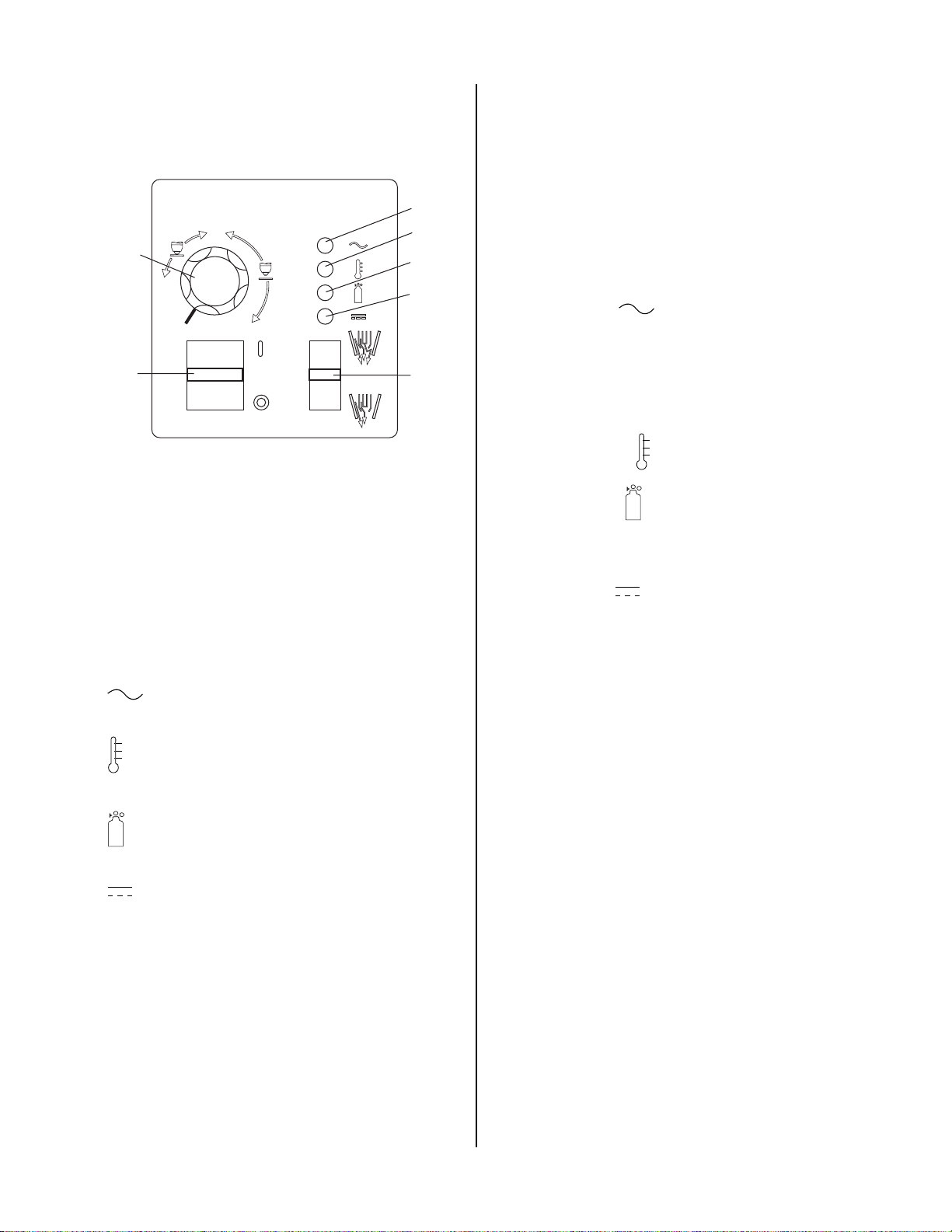
A. Controls and Indicators
A
40
3
20
60
1
3. Set the Power Supply controls as follows:
• ON/OFF switch to OFF (Down)
• RUN/SET switch to SET (Down)
• CURRENT control (A) to maximum
4
5
6
C. Main Input and Internal Power Tests
1. Connect main AC power to the unit.
2. Set the Power Supply ON/OFF switch to ON (up) and
note the following:
7
• AC indicator blinks for eight seconds (approximately), then steady ON
• Relay K4 on Main PC Board energizes (clicks) while
2
AC indicator is blinking
• Relay K5 energizes pulling in W1 after AC light
stops blinking.
A-03208
1. ON/OFF switch. This switch controls AC power to
unit. Up is ON, down is OFF.
2. RUN/SET switch. This switch controls gas to torch.
Up is RUN, for general torch operation. Down is SET ,
for setting gas pressure and purging lines.
3. Current control knob. This control regulates current
to torch. At output settings over 40 amps, cir cuitry in
the power supply automatically reduces output current to 40 amps if the torch tip contacts the workpiece.
4. AC indicator. When lit, indicates operating
power is present in the unit.
5. TEMP indicator. Indicator comes on when inter-
nal sensors detect temperatures above normal limits.
6. GAS indicator. Indicates adequate supply pres-
sure is present in the unit.
7. DC indicator. Indicates DC power output cir-
cuit is active. (Torch must be activated).
B. Initial Setup Conditions
This section is to help isolate the defective circuit before
troubleshooting, identify symptoms, and test the unit for
proper operation. Follow the instructions as given to identify the possible symptom(s) and the defective circuit.
After repairs are complete, run the following tests again
to verify that the unit is fully operational.
• TEMP Indicator OFF
• GAS Indicator ON
• Gas flows
• Fans operate
• DC lndicator is OFF
3. Set the Power Supply RUN/SET switch to the RUN
(up) position and note the following:
• GAS indicator goes OFF
• Gas flow stops
This completes the Main Input and Internal Power T ests.
If the above are all correct then pr oceed to paragraph 'D'.
If not, note the symptom and proceed to Subsection 4.07,
Main Input and Internal Power Problems.
D. Pilot Arc Test
1. Activate the torch to establish a pilot arc and note the
following:
• Gas flows
• GAS indicator turns ON
• Preflow delay (two seconds) then DC indicator turns
ON
• Pilot arc established
This completes the Pilot Arc Test. If the above are all correct then proceed to paragraph 'E'. If the unit does not
function properly, then note the symptom and proceed
to Subsection 4.08, Pilot Arc Pr oblems.
1. Connect gas supply to rear of Power Supply .
2. Turn on gas supply and adjust Power Supply Gas
Regulator to 70 psi (4.8 bar).
SERVICE 4-4 Manual 0-2871
Page 23

E. Main Arc Test
A-03001
Lower
screws
Upper screws
Ground wire
Lower
screws
Upper
screws
Make sure the work cable is firmly connected to the workpiece. Activate the torch to establish a pilot arc.
Bring the torch to within 1/8"-3/8" (3-10 mm) of the workpiece to establish the main cutting arc, and note the following:
• Main cutting arc starts
• Pilot Control Relay (PCR) opens
This completes the Main Arc Test. If the above are all
correct then the equipment should be operating properly.
If problems still persist then contact Technical Services.
If the torch does not function as noted then note the symptom and proceed to Subsection 4.09, Main Ar c Problems.
4.07 Main Input and Internal Power
Problems
A. Opening Power Supply Enclosure
The Power Supply cover must be removed for access to
input power connections and test points.
WARNING
Disconnect primary power at the source before assembling or disassembling the Power Supply, torch
parts, or torch and leads assemblies.
1. Remove the upper screws securing the cover to the
main assembly.
2. Loosen, but do not remove, the lower screws.
NOTE
There is a ground wire attached from the cover to
the main body of the unit.
3. Carefully lift the cover off the unit, and remove the
nut securing the ground wire to the side panel.
4. Re-install the cover by reversing the above steps.
Cover Removal
Locate your symptom below:
A. Main power line fuses blow as soon as main
disconnect is closed
1. Input power cable installed incorrectly or defective
power cord.
a. Refer to Subsection 5.07-E, Input Power Cable
Replacement procedures, and check that the input power cable is not defective or installed
incorrectly. Section 4.10-D illustrates wiring
connections.
B. Main power line fuses blow immediately after the
ON/OFF Switch is turned on.
1. Faulty Input Diode
a. Test Input Diode per Subsection 4.10-C; repair
as necessary.
C. Fan does not operate; AC indicator on front panel
of power supply is OFF
1. Front Panel ON/OFF switch in OFF position
a. Place switch to ON (up) position.
Manual 0-2871 4-5 SERVICE
Page 24

2. Main power disconnect switch open
a. Close main power disconnect switch.
3. Main power line fuses blown
a. Replace main power line fuses.
4. Improper input power cable connections inside Power
Supply
a. Refer to System Schematic and correct if
needed.
J23-1
J23-3
J24-3
J24-4
Main PC Board
J18-3
J18-4
J18-5
J18-6
5. Defective input power cable
a. Replace input power cable. Refer to Section
5.07-E.
6. Fuse blown inside Power Supply
a. Replace internal Fuse per Subsection 5.06-A.
7. Line voltage above 10% tolerance (over voltage protection)
a. Reduce line supply .
8. Faulty Auxiliary Transformer (refer to Appendix 12,
28 VAC Circuit Diagram)
Measure for 28 VAC on Main PC Board from
J18-1 to J18-3.
a. If voltage is not present, replace the Main PC
Board.
J23-1
J23-3
J24-3
J24-4
J18-3
J18-4
J18-5
J18-6
A-03171
10. Faulty Main PC Board (refer to Appendix 4, Main PC
Board Layout).
Measure for 12 vdc on Main PC Board from TP4
to TP6.
a. If voltage is not present, replace the Main PC
Board.
D. System will not pilot; AC indicator ON, TEMP
indicator ON
1. Air flow through unit is restricted
a. Provide adequate air flow (Refer to Operating
Manual, Subsection 3.02, Site Selection).
2. Exceeded Duty Cycle of Power Supply
a. De-activate torch and wait for fan to cool unit.
Refer to Section 3 for proper duty Cycle for this
unit.
3. Faulty Fan(s)
Measure for 230 VAC (±) on the Main PC Board
from J15-1 to J15-5, and from J15-2 to J15-6.
Main PC Board
• If voltage at J15-1 to J15-5 is correct, replace
lower Fan (M1).
• If voltage at J15-2 to J15-6 is correct, replace
upper Fan (M2).
A-03171
9. Faulty ON/OFF switch (refer to Appendix 12, 28 VAC
Circuit Diagram).
Measure for 28 VAC on the Main PC Board between J18-5 to J18-6.
a. If voltage is not present replace the ON/OFF
Switch.
SERVICE 4-6 Manual 0-2871
Page 25

J15
3. Faulty Wiring or Faulty Logic PC Board
Fuse
Check for 12 vdc at Main PC Board pin J24-3 to
J24-4 from the Logic PC Board. Refer to Appendix 4, Main PC Board Layout.
Auxiliary
Transformer
Main PC Board
INPUT
DIODE
A-03172
J15-1
J15-2
J15-5
J15-6
E. No gas flow; AC indicator ON; TEMP indicator
OFF; GAS and DC indicators OFF
1. RUN/SET switch in RUN (up) position
a. Switch to SET (down) position.
2. Gas supply not connected to unit
a. Connect to gas supply.
3. Gas supply not turned on
a. Turn gas supply on.
4. Faulty RUN/SET switch
a. Check continuity.
5. Faulty Gas Solenoid circuit
a. Test Gas Solenoid circuit per Subsection
4.10-E; repair as necessary.
F. Gas flows; AC indicator ON; GAS indicator OFF;
DC indicator OFF
1. Gas pressure too low
a. Refer to Torch Instruction Manual for operat-
ing pressures.
2. Faulty Pressure Switch
Measure for 12 vdc from wire #10 to wire #11 at
the Gas Pressure Switch, located on the right side
of the unit. Refer to Appendix 14/15, System Schematic.
a. If 12 vdc is present and pressure is above 50 psi
(3.4 bar), replace Gas Pressure Switch/Solenoid
Assembly. Refer to Section 5.08-A.
b. If pressure is above 50 psi (3.4 bar) and 12 vdc
is not present, replace the Logic PC Board.
• If less than a volt, replace Logic PC Board.
J23-1
J23-3
J24-3
J24-4
Main PC Board
J18-3
J18-4
J18-5
J18-6
A-03171
G. Gas continues to flow with RUN/SET switch in
RUN position.
1. Damaged gas solenoid.
a. Turn the front panel ON/OFF switch to OFF.
• If gas continues to flow , debris from the air line
is preventing the solenoid from closing. Clean
or replace the solenoid.
2. Faulty RUN/SET switch.
a. Check continuity.
3. Faulty Logic PCB.
a. Measure for approximately 12 vdc between
P1-7 and TP-1 on the Logic PCB.
• If 12 vdc is present, replace Logic PCB.
• If less than 2 vdc, replace Main PCB.
H. Arc in torch without activating torch; Gas flows;
AC indicator ON; GAS and DC indicators ON
1. Faulty torch switch
a. Refer to appropriate Tor ch Instruction Manual
and check continuity.
2. Faulty torch leads
a. Refer to appropriate Tor ch Instruction Manual
and check continuity.
3. Faulty Power Output PC Board (Refer to Appendix
11, Power Output PC Board Diagram)
a. Disconnect J41 Connector from the Power Out-
put PC Board.
b. Unplug Logic PC Board.
Manual 0-2871 4-7 SERVICE
Page 26

c. Measure across pins J41-1 and J41-3 on Power
Output PC Board.
• If less than 2K ohms, replace Power Output
PC Board.
• If more than 2K ohms, replace Logic PC
Board.
d. Check for damaged torch leads. If pilot wire
arcs to torch switch PIP lead it can damage PCB
and the torch leads.
2. Faulty Output Power PC Board
a. With ON/OFF switch in the OFF position, dis-
connect J39 from the Output Power PCB. Activate the torch and check for continuity between
J39-6 and J39-7 on Output Power PCB.
• If no continuity is found, check for continuity between J41-1 and J41-3. If continuity is
found, replace the Power Output PCB.
• If no continuity, check the tor ch connection.
If torch connection is okay , r eplace the torch.
J41-1
A-03173
J41-3
Power Output PC Board
Output Diode A
4.08 Pilot Arc Problems
W ARNING
The following tests must be performed with the
power supply connected to primary input power.
There are extremely danger ous voltage and power
levels present inside this unit. Do not attempt to
diagnose or repair without proper training in power
electronics measurement and troubleshooting techniques.
J39-6
J39-7
Power Output PC Board
Output Diode B
A-03266
3. Faulty Logic PCB
a. With torch activated, check indicator D20 on
the Logic PCB. Replace Logic PCB if D20 is on.
B. Gas flows; small arc may be visible in torch; AC
indicator ON; TEMP indicator off; GAS indicator
ON; DC indicator off or blinks on/off once.
1. Faulty torch
a. Disconnect and isolate the Pilot return wire
from the Power Supply. Activate the torch and
observe the front panel DC LED.
Locate your symptom below:
A. No gas flow; AC indicator ON; TEMP indicator
on, replace the torch.
2. Faulty IGBT or Output Diode Module Assembly(s)
off; GAS and DC indicators OFF (Torch Switch,
• If the DC indicator comes on and remains
CNC Control Switch or Pendant Control switch
must be pressed)
1. Faulty torch or leads
a. Check per Subsection 4.10-C; repair as needed.
3. Faulty Main PCB
a. Test per Subsection 4.10-F; repair as needed.
a. Test per Torch Instruction Manual.
SERVICE 4-8 Manual 0-2871
Page 27

C. Gas flows; No arc in torch; No arc at spark gap on
CD PC Board; AC indicator ON; TEMP indicator
off; GAS and DC indicators ON; CD enable
indicator ON
D. No arc or intermittent arc in torch; Gas flows;
Spark at gap on CD PC Board; AC indicator ON;
TEMP indicator off; GAS and DC indicators ON;
and CD enable indicator ON
1. Faulty IGBT
a. Measure between the following points on the
IGBTs: (Refer to Appendix 4)
• IGBT A: E4 to E10
E10 to E20
•IGBT B: E23 to E27
E27 to E30
V oltage should be approximately 20 vdc befor e
the start signal is active. If voltage measures
approximately 440 vdc when the start signal is
active, replace the respective IGBT(s).
2. Faulty CD PC Board. (Refer to Appendix 6, CD Board
Layout)
a. Measure for approximately 12 vdc at J28-1 to
TP-6 (on Main PC Board) when the torch is activated. Measure for less than 2 vdc at J28-2 to
TP6 (on Main PC Board).
• Check for approximately 250 V AC between pin
J28-5 and J28-8 on CD PC Board.
• If voltages are not present, check all wiring and
connections. If wiring is connected properly
and is not shorted, replace the main transformer.
b. Check for OCV at E61 to E64 on Power Output
PC Board.
• If voltage is present, and the other measure-
ments above are correct, replace CD Boar d.
1. Gas pressure set incorrectly (too high)
a. Refer to appropriate Tor ch Instruction Manual.
2. Oil/moisture in air lines
a. Purge system. If problem corrected, add filters
in line with air source.
3. Incorrect torch parts
a. Refer to appropriate Tor ch Instruction Manual.
4. Faulty leads
a. Check continuity per appropriate T or ch Instruc-
tion Manual.
5. Faulty torch
a. Check continuity per T orch Instruction Manual.
6. Faulty connection of wire #58 or 62 to Main PC Board
a. Check wiring connection. Refer to the appro-
priate System Schematic in the Appendix.
7. Faulty Main PC Board
a. Check for approximately 12 vdc at TP2 to TP1.
If less than 2 vdc, replace the Main PC Board.
8. Faulty Logic PCB or Faulty PCR Relay
a. Visually check that the pilot control relay (PCR)
is closed. If not, check for approximately 12
vdc across the coil.
• If approximately 12 vdc is present, replace
the relay.
• If there is no 12 vdc across the coil, replace
the logic board.
b. Install a jumper between wires 58 and 62 on
PCR relay and retry piloting. If torch pilots with
jumper installed, replace PCR Relay.
J28-1
J28-2
CD PCB
A-03175
Manual 0-2871 4-9 SERVICE
Page 28
4.09 Main Arc Problems
4.10 Test Procedures
Locate your symptom below:
A. Main cutting arc will not initiate
1. Work cable not connected.
a. Connect work cable.
2. Holding too high of a standoff.
a. Refer to Torch Instruction Manual for recom-
mended standoff heights.
3. Workpiece is painted or rusty.
a. Clean workpiece.
4. Faulty Main PC Board or Logic Board.
a. Measure for ±0 vdc at TP2 to TP1 on the Logic
Board when attempting to transfer. Refer to
Appendix 3.
• If TP2 goes to 0 vdc replace Logic Board.
• If not, replace Main PC Board.
5. Faulty Main Input Contactor.
a. Check per Subsection 4.10-D.
B. When operating the amperage drops off after the
main cutting arc initiates.
1. Torch tip contacts work.
The test procedures in this subsection are referenced in
the troubleshooting section.
A. Safety Precautions
1. Significant DC Voltage exists after removal of input
power . Allow two minutes for discharge time. Voltage measured on input capacitors must be zero before performing service on the power supply.
2. Do Not touch electrical components with any part of
the human body when power is applied.
3. Keep away from any moving parts.
4. Hot surfaces can cause severe burns. Allow equipment to cool before servicing.
5. Electrostatic discharge can damage printed circuit
board assemblies. T ransport printed cir cuit boards in
proper antistatic shielded packages. Use proper
grounding techniques with wrist strap before handling
printed circuit boards.
6. Misaligned plugs can cause printed circuit board damage. Be sure plugs are properly aligned and completely seated.
7. Excessive pressure can damage printed cir cuit boards.
Use only minimal pressure and gentle movement
when disconnecting or connecting printed circuit
board plugs.
Lift the torch tip off the work. At output settings over 40 amps, circuitry in the power supply automatically reduces output current to 40
amps if the torch tip contacts the workpiece.
2. Faulty Pilot (PCR) Relay
a. With power off, measure for continuity between
wires #58 and #62. Refer to the System Schematic in the Appendix. If continuity is found,
replace PCR.
B. Diode Testing Basics
WARNING
Disconnect primary power at the source before disassembling the power supply, torch, or tor ch leads.
T esting of diode modules r equires a digital volt/ohmmeter that has a diode test scale. Remember that even
if the diode module checks good, it may still be bad.
If in doubt, replace the diode module.
1. Locate the diode module to be tested.
2. Remove cables from mounting studs on diodes to isolate the module.
3. Set digital volt/ohmmeter to diode test scale.
4. Using the Figures for each test, check each diode in
the module. Each diode must be checked in forward
bias (plus to negative) and reverse bias (negative to
plus) direction.
SERVICE 4-10 Manual 0-2871
Page 29

5. Connect the volt/ohmmeter positive lead to the anode (+) of the diode and the negative lead to the cathode (-) of the diode for forward bias testing (refer to
following figure). A properly functioning diode will
conduct in the forward bias direction and indicate between 0.3 to 0.9 volts.
A-00307
0.75
C. Diode Module Board Tests
WARNING
Disconnect primary power at the source before taking any resistance checks.
1. Input Diode Module Board Circuit Test
a. Remove AC power. Refer to Appendix 5-A or 5-B,
Main Power Wiring diagram.
Forward Bias
Diode Conducting
Diode T est Symbol
Anode
Cathode
VR
+
COM
_
A
Testing Diode Forward Bias
6. Reverse the meter leads across the diode for reverse bias testing (refer to following figure). A
properly functioning diode will block in the reverse bias direction and depending on the meter
function will indicate an open or “OL”.
7. If a diode checks bad, replace the diode module.
8. Reconnect all cables.
b. Check Input Diode for shorted input diode. With
an ohmmeter set on the diode range make the following checks from Main PC Board to Input Diode:
Input Diode PCB
Meter (+) M eter (-) Indicat i on
E7 E1 Open
E1 E7 Diode Drop
E15 E1 Diode Drop
E1 E15 Open
E15 E7 Diode Drop *
E7 E15 Open
* Indicat i on c an be t wi c e
other indications.
c. The meter should indicate a diode drop in one di-
rection and an open in the other direction for each
check. Replace the Input Diode Module Board if
the readings do not match the chart.
d. If Input Diode Module Boar d is shorted, make the
following checks with an ohmmeter at the Main
Contactor (W1):
A-00306
Met e r (+) Met er (-) Indication
L1 T1 Open
OL
L2 T2 Open
L3 T3 Open
Reverse Bias
Diode Not Conducting
Cathode
Anode
VR
+
COM
_
A
If any test has resistance, then replace the Main Contactor.
Testing Diode Reverse Bias
Manual 0-2871 4-11 SERVICE
Page 30

2. Output Diode Module Board Circuit Test
a. Use an ohmmeter set on the diode function and
make the following measurements on the Output
Diode Module Boards to Power Output PC Board.
D. Main Input Power Test
W ARNING
Output Diode A Output Diode B
Met er + Meter - M et er + M et er -
E37 E58 E36 E57 Diode Drop *
E58 E37 E57 E36 Open
E37 E47 E36 E49 Diode Drop
E47 E37 E49 E36 Open
E58 E47 E57 E49 Open
E47 E58 E49 E57 Diode Drop
* Indicat i on c an be t wi c e ot her i ndications .
Indication
b. The meter should indicate a diode drop in one di-
rection and an open in the other direction for each
check. Replace the Output Diode Module Board(s)
if the readings do not match the chart.
3. IGBT Module Board Circuit Test
a. Use an ohmmeter set on the diode function and
make the following measurements on the IGBT
Module Board(s) to the Main PC Board.
IGBT PCB A IGBT PCB B
Met er + M eter - Meter + Meter -
E10 E4 E27 E 23 Diode Drop
E4 E10 E23 E27 Open
E10 E20 E27 E30 Open
E20 E10 E 30 E27 Diode Drop
E4 E20 E23 E30 Open
E20 E4 E30 E 23 Diode Drop *
* Indicat i on c an be t wi c e ot her i ndications .
Indication
b. The meter should indicate a diode drop in one di-
rection and an open in the other direction for each
check. Replace IGBT Module Board(s) if readings
are not the same as the chart.
The following tests must be performed with the
power supply connected to primary input power.
There are extremely dangerous voltage and power
levels present inside this unit. Do not attempt to
diagnose or repair without proper training in power
electronics measurement and tr oubleshooting techniques.
Reconnect power and observe proper start-up procedure.
AC LED Indicator on the Front Panel should be ON. If
indicator is OFF there is no voltage to the Power Supply
or an overvoltage condition exists.
1. If AC LED Indicator on Front Panel is OFF, check
for proper AC input voltage between input cables
on the Main Contactor. Input voltage should be
187-253VAC between contactor points L1 and L2.
If not, check for proper voltage at the main power
source.
#78
#3
#2
#1
T1 T2 T3 T4
L1 L2 L3 L4
L2
L1
#5
#12
#13
#4
Input
Side
A-03212
Main Input Contactor
2. Check for 28 VAC at J23-1 to J23-3 on the Main PC
Board.
a. If greater than 30 V AC, input line power is too
high.
b. If there is no AC power, check the fuse. If the
fuse is ok, the auxiliary transformer is faulty.
Replace the Main PC Board.
SERVICE 4-12 Manual 0-2871
Page 31

E. Gas Solenoid Circuit Test
Make the following voltage checks and replace the faulty
part as required.
1. Place the RUN/SET Switch to the SET position.
2. Measure for 28 V AC across Solenoid wir es #8 and
#9. Refer to System Schematic in Appendix Section.
• If 28 V AC is present, replace Solenoid/Pressur e
Switch Assembly .
W ARNING
The following tests must be performed with the
power supply connected to primary input power.
There are extremely dangerous voltage and power
levels present inside this unit. Do not attempt to
diagnose or repair without proper training in power
electronics measurement and tr oubleshooting techniques.
• If 28 VAC is not present, check for 70 psi (4.8
bar) at the pressure regulator.
3. Check for less than 2 vdc at P1-14 to TP1 on Logic
Board.
• If less than 2 vdc, replace Main PC Board.
• If more than 2 vdc, replace Logic PC Board.
F. Output Power Tests
1. No DC Output
Activate the torch.
• If INV ON indicator D21 on Logic PC Board does
not turn ON, then replace the Logic PCB.
• If the INV ON indicator D21 blinks ON then OFF
immediately, perform the following test:
a. Disconnect J28 from the CD PC Board to dis-
able the CD signal.
WARNING
Connector J28 on the CD PC Board must be disconnected to prevent electrical damage to measuring equipment when testing the open circuit voltage (OCV).
b. Activate the torch. Logic PC Board Inverter
ON Indicator , D21, turns ON.
c. Activate the torch.
• After 2 seconds D21 on the Logic PCB should
turn ON. If D21 does not turn ON, replace
Logic PCB.
d. Measure open circuit voltage between E61(+) to
E43 (-) at the Output Power PC Board. Voltage
should be greater than 200 V. If voltage is less than
10 V, refer to the output diode test measurements
or IGBT module test measurements or shorted
torch measurements.
4. Gate Drive & DC Sensing
a. After checking all previous steps in Subsection
4.10-G, jumper TP1 to TP7 on the Logic PCB. Re-
fer to Appendix 3.
b. When the unit is turned on, the DC light
should remain ON.
c. Activate the torch. After two seconds INV ON
Indicator on the Logic PCB should come on and
remain on.
• If INV ON indicator does not remain on, replace Logic PCB.
• If INV ON indicator remains on, then check
for approximately 6 vdc between TP-1 to TP-4
and between TP-1 to TP-8 on the Logic PCB.
Refer to Appendix 3.
• If no voltage, replace Logic PC Board.
c. Measure open circuit voltage between E61(+)
to E43(-) on the Power Output PC Board. Voltage should be 200-300 Volts. If voltage is less
than 10 V, each IGBT Module and Output Diode Module should be tested individually.
Manual 0-2871 4-13 SERVICE
• If voltage is correct, measure for approxi-
mately 6 vdc between points as in the following chart:
IGB T A IGB T B
E11 J2A E11 J2B
E19 J10A E19 J10B
• If voltage is 0, replace Main PCB.
• If voltage is correct, proceed to the following step.
Page 32

d. With jumper between TP1 to TP7 still in place, ac-
tivate the torch and measure for 250 vdc to 300
vdc between E61 (+) and E43 (-) on the Power
Output PCB. Refer to Appendix 11.
• If voltage is 0 vdc, replace IGBT Module.
e. W ith jumper between TP-1 and TP-7 still in place,
activate the torch and measure for approximately
250-300 vdc between J39-1 and J39-2.
• If voltage is 0 vdc, replace Output Power PCB.
• If voltage is correct, replace Logic PCB.
This completes the test procedures.
SERVICE 4-14 Manual 0-2871
Page 33

SECTION 5:
REPAIRS & REPLACEMENT
PROCEDURES
5.01 Scope
This section describes parts replacement procedures
which may be performed on the Firepower FP-82 Power
Supply.
Under no circumstances are field repairs to be attempted
on Printed Circuits or other subassemblies of this unit.
Evidence of unauthorized repairs may void the factory
warranty.
5.02 Anti-Static Handling Procedures
B. Procedure
1. Open the wrist strap and unwrap the first two folds
of the band. W rap the adhesive side firmly around
your wrist.
2. Unroll the rest of the band and peel the liner from
the copper foil at the opposite end.
3. Attach the copper foil to a convenient and exposed
electrical ground.
4. Connect the equipment primary cable ground to
the same electrical ground as the wrist strap.
5. Open the equipment enclosure and remove the
failed PC board.
6. Carefully open the ESD protective bag and r emove
the replacement PC Board.
7. Install the replacement PC Boar d in the equipment
and make all necessary connections.
A. General
Caution: PC Boards can be irreparably damaged by improper handling due to electrostatic discharge (ESD).
Replacement PC Boards are shipped in a protective enclosure to prevent damage from electrostatic discharge
(ESD) during shipping. A gr ound strap is included with
each replacement board to prevent static damage during
installation.
WARNINGS
Read and understand these instructions and the
instructions on the grounding wrist strap package
before opening the equipment enclosure or removing the replacement PC board from its protective
enclosure.
Disconnect primary power to the system before disassembling the torch, torch leads, or power supply
enclosure.
Where these instructions include specific torquing
instructions, failure to torque properly will cause
component damage.
8. Place the failed PC Board in the ESD protective
bag and seal for return shipping.
9. Replace the power supply cover.
10. Remove the grounding wrist strap from your wrist
and from the electrical ground connection before
reconnecting primary power to the equipment.
5.03 Parts Replacement - General Information
The parts replacement procedures described in this
manual, except for filter replacement, require that the
Power Supply be disassembled. The part to be replaced
will determine to what extent the Power Supply must be
disassembled.
Before removing any connection mark each wire with the
connection designation. When reassembling make sure
the wires go to the proper terminals.
Note the routing of wires and make sure the wires are
put back in the same place when re-assembling the unit.
Each subsection is referenced to Section 6 for parts lists
and overall detailed drawings.
Do not operate the equipment or test equipment
under power while wearing the grounding wrist
strap.
Disconnect primary power from the source before
opening or disassembling the power supply.
Before disassembling any part of the Power Supply first
read the procedure for the part to be replaced, then proceed with the disassembly.
Manual 0-2871 5-1 REPAIRS & REPLACEMENT PROCEDURES
W ARNING
Page 34

5.04 Major External Parts Replacement
B. Tube Handle Replacement
1. Remove the cover per subsection 5.04-A.
Refer to Section 6.03 for Major External Replacement Parts
and overall detailed drawing.
WARNING
Disconnect primary power from the source before
opening or disassembling the power supply.
A. Cover Replacement
1. Remove the upper screws securing the cover to
the unit. Loosen the lower screws securing the
cover to the base.
Upper
screws
Upper screws
Lower
screws
2. Remove the Fan Assembly Panel per section
5.08-C.
3. Remove the four bolts and star washers securing
the frame to the base of the unit.
4. Move the input power cable, torch leads and work
cable inside the handle. Lift the base of the unit
away from the T ube Handle. Leave the rear panel
fastened to the base assembly.
5. W ith a rubber mallet, separate the two handle ends
as shown below.
6. Install the replacement Tube Handle by r eversing
steps 1-4.
7. Replace the Fan Shroud per section 5.08-C.
8. Re-install the Power Supply cover.
Lower
screws
Ground wire
A-03001
2. Carefully lift the cover up and away from the unit
for access to the ground wire connection on the
inside of the cover.
3. Remove the nut and washer from the ground stud
on the inside of the cover .
4. Install the replacement cover by reversing the above
steps.
A-02847
REPAIRS & REPLACEMENT PROCEDURES 5-2 Manual 0-2871
Page 35

5.05 Front Panel Parts Replacement
A-02775
Wire #25
Wire #26
Top clip
C. RUN/SET Switch Replacement
Refer to Section 6.04 for Front Panel Replacement Parts
and overall detailed drawing.
WARNING
Disconnect primary power from the source before
opening or disassembling the power supply.
A. Current Control Knob Replacement
1. Turn the Current control knob fully clockwise and
note the location of the pointer on the knob.
2. Loosen the screw securing the Curr ent Knob to the
potentiometer shaft and remove the Current Knob.
3. Place the replacement Current Knob on the potentiometer shaft with the location of the pointer the
same as noted in step 1.
4. Tighten the screw to secure the knob to the potentiometer shaft.
B. ON/OFF Switch Replacement
1. Remove the cover per subsection 5.04-A.
2. Disconnect the two wires on the rear of the RUN/
SET Switch. Note the location of each wire, as
shown:
3. Squeeze together the clips on the top and bottom
of the RUN/SET Switch, then remove the switch
through the Front Panel.
4. Install the replacement RUN/SET Switch by reversing the above steps.
D. POT/LED PC Board Replacement
1. Remove the cover per subsection 5.04-A.
2. Disconnect the four wires on the rear of the ON/
OFF Switch. Note the location of each wire, as
shown below:
Top clip
Wire #21
Wire #24
Wire #22
Wire #23
A-02774
3. Squeeze together the clips on the top and bottom
of the ON/OFF Switch. Remove the Switch
through the Front Panel.
4. Install the replacement ON/OFF Switch by r eversing the above steps.
Follow the antistatic procedures provided in subsection
5.02.
1. Remove the cover per subsection 5.04-A.
2. Remove Current Knob per subsection 5.05-A.
3. Disconnect J Connector fr om POT/LED PC Board.
4. Remove PC Board from standoffs.
5. Install the replacement POT/LED PC Board by reversing the above steps.
E. Work Cable Replacement
1. Remove the cover per subsection 5.04-A.
2. Disconnect the Work Cable from the WORK terminal on the Power Output PC Board, located on
the right side of the unit.
3. Squeeze the top and bottom of the Work Cable
Strain Relief and remove from the Front Panel.
4. Remove Work Cable from the unit.
5. Install the replacement Work Cable as follows:
a. Ensure that the replacement Work Cable passes
through the grommet in the Fan Shroud.
b. Secure the Cable to the Work terminal on the
Power Output PC Board and secure the strain
relief.
Manual 0-2871 5-3 REPAIRS & REPLACEMENT PROCEDURES
Page 36

5.06 Left Side Internal Component Parts Replacement
Refer to subsection 6.05 for Left Side Internal Component Replacement Parts and overall detailed drawing.
WARNING
Disconnect primary power from the source before
opening or disassembling the power supply.
A. Fuse Replacement
1. Remove the cover per subsection 5.04-A.
2. Locate the Fuse near the top edge of the Main
Power PC Board and remove the Fuse from the
fuse holder .
3. Install replacement fuse.
4. Reinstall the cover.
B. Main Input Contactor Replacement
1. Remove the cover per subsection 5.04-A.
2. Label all wires connected to the Input Contactor.
3. Disconnect wires to the Input Contactor from the
input cable.
4. Disconnect all other wires connected to the Input
Contactor.
5. Remove the two nuts and washers securing the
Input Contactor to the base of the power supply.
6. Position the replacement Input Contactor with the
row of connectors labeled L towar d the rear of the
Power Supply. Fasten in place with the hardware
removed previously.
7. Complete the wiring connections as shown below.
NOTE
It is important that wires are installed correctly , as
shown, to prevent damage to the unit.
#78
#3
#2
#1
T1 T2 T3 T4
L1 L2 L3 L4
L2
L1
#5
#12
#13
#4
Input Contactor
C. Logic PC Board Replacement
Follow the antistatic procedures in subsection 5.02. The
Logic PC Board connects to the Main PC Board through
an extender board perpendicular to both boards.
1. Remove the cover per subsection 5.04-A.
2. Refer to Section 6.05, Left Side Internal Replacement Parts. Remove the bolts in each corner of
the Logic PC Board.
3. Detach the Logic PC Board and the extender boar d
from the Main Power PC Board. Detach the extender board from the Logic Board.
4. Install the replacement Logic PC Board by reversing the above steps. The pins on the right edge of
the Logic PC Board must fully engage the sockets
on the edge of the extender board. The extender
board must fully engage sockets on the Main
Power PC Board.
Input
Side
A-03212
8. Reinstall cover.
REPAIRS & REPLACEMENT PROCEDURES 5-4 Manual 0-2871
Page 37

D. IGBT Circuit PC Board or Input Diode PC
Board Replacement
Follow the antistatic procedures in subsection 5.02. The
Power Supply includes two IGBT Circuit PC Boards.
NOTE
Follow the electrostatic discharge instructions provided with the replacement component to prevent
damage to the component.
9. Install replacement components as follows:
For input diodes: A new style input diode assembly replaces the old style input diode assembly.
Old Style Assembly
Round Thermal
Pad
Thermal pads, heatsinks, and the large flat surface
on the back of diodes and IGBT s must be kept clean.
Diodes and IGBTs must not be bent or allowed to
pick up any foreign material. A very clean installation between the module and the heatsink or chassis is essential for proper operation.
1. Remove cover per subsection 5.04-A.
2. Turn the Power Supply onto its side.
3. Locate the IGBT Circuit PC Boards or Input Diode
mounted within the Main Power PC Board. Refer
to Appendix pages for location and position.
4. For IGBTs, remove the small jumpers between the
IGBT and the Main PC Board. T ransfer these jumpers to the replacement IGBT. Label, then remove
all other wire connections to the Board(s) being
replaced. Note the routing of wires. Ensure that
the wires are put back in the same place when installing the replacement module.
5. Remove screw(s) securing PC Boar d(s) to the heatsink and remove board(s) fr om the Power Supply .
6. For input diodes only:
If there is a solid metal disk attached to the heat-
sink, remove it by twisting it and pulling it away
from the heatsink. Discard the disk.
7. Use isopropyl alcohol to clean and a clean rag to
clean the heatsink or chassis area behind the component being replaced. Clean the large flat surface on the back of the replacement component.
Do not scratch or abrade the surface.
8. The thermal pad(s), provided with the replacement
part, is a thin metal pad. Remove any loose protective paper coverings from the pad(s).
NOTE
Protective coverings must be removed from the
thermal pads. Installing thermal pads with protective coverings in place will cause equipment
damage or failure.
Diode
Screw
Rectangular
Thermal Pad
Washer
Solid Disk
New Style Assembly
Thermal Pad
Diode
Assembly
A-03446
a. Apply the rectangular thermal pad to the cen-
ter chassis with a small piece of light-duty tape.
T ape must cover no mor e than 1/8” (3 mm) of
the edge of the thermal pad. Use the screw
holes in the chassis as a guide to position the
pad. Align the pad to match the position of
the rectangular flat surface on the back of the
input diode.
b. Secure the diode and rectangular pad to the
chassis with the replacement screws and washers. Ensure that the rectangular pad is aligned
with the rectangular flat surface on the back of
the diode.
For IGBTs:
a. Remove the small jumpers from the component
being replaced and transfer them to the replacement component.
b. Secure replacement board(s) with the screw re-
moved previously. Ensure that the washer is
under the head of the screw.
10. To rque screw to 17 in-lb. (1.9 Nm).
NOTE
Failure to torque properly will cause component
damage.
Manual 0-2871 5-5 REPAIRS & REPLACEMENT PROCEDURES
Page 38

11. Connect wires per the following applicable
chart(s).
Firepower 82 Input Diode Connections
Input Diode To Main P CB
E18 E3
E13 E2
E5 E1
E14, E 16 E15
E6, E8 E7
6. Remove the Logic Board standoffs.
7. Carefully remove the original PC Board from the
unit.
8. Install the replacement PC Board by reversing the
steps above. It may be easier to install the PC Board
if the Power Supply is turned on its right side first.
Refer to the charts in subsection 5.06-D for input
diode and IGBT wiring connection points.
5.07 Rear Panel Par ts Replacement
Firepower 82 IGBT Connect i ons
IGBT A IGBT B
IGBT A
Connector
J3 J25 J3 J31
J7 J30 J7 J26
E9, E11 E10 E9, E11 E27
E19, E 21 E20 E 19, E21 E 30
E12, E 17 E 4 E 12, E17 E 23
To Main PCB
Connector
IGBT B
Connector
To Main PCB
Connector
12. Stand the unit upright; reinstall the cover.
E. Main Power PC Board Replacement
Follow the antistatic procedures in subsection 5.02.
1. Remove cover per subsection 5.04-A.
2. Remove the Logic PC Board per subsection 5.06-C.
3. Label and disconnect all wire and cable connections to the Main PC Board. Refer to the Main PC
Board Wiring Diagrams in the Appendix Pages if
necessary. Straighten the connections to the
smaller PC Boards to be perpendicular to the Main
PC Board.
4. Remove the two long Transformer screws securing the Transformer to the Center Chassis.
Refer to subsection 6.02 for parts list and overall detailed
drawing.
WARNING
Disconnect primary power from the source before
opening or disassembling the power supply.
A. Filter/Regulator Assembly Replacement
WARNING
Disconnect the gas supply at the source and bleed
down the system before attempting this procedure.
1. Disconnect the gas input hose from the Filter/
Regulator Assembly on the Rear Panel of the unit.
2. Remove the four bolts securing the Regulator
Mounting Bracket to the Rear Panel.
3. Disconnect the black gas tube from the Filter/
Regulator Assembly Adapter Fitting. Hold a
wrench or similar tool against the locking ring on
the Fitting and pull on the tube to release it.
5. Remove the other screws securing the PC Board
to the Center Chassis.
4. Remove the nut securing the Filter/Regulator Assembly to the Regulator Mounting Bracket. Remove the Filter-Regulator Assembly from the
Mounting Bracket.
5. Transfer the pressure gauge fr om the original Filter/ Regulator Assembly to the replacement assembly.
Screw locations
NOTE
For a secure seal, apply thread sealant to the fitting threads, according to manufacturer's instructions. Do Not use Teflon tape as a thread sealer as
small particles of the tape may break off and block
the small gas passages in the torch.
A-03165
REPAIRS & REPLACEMENT PROCEDURES 5-6 Manual 0-2871
Page 39

6. Install the replacement Filter/Regulator Assembly by reversing the steps above. When connecting the gas tube to the Adapter Fitting, simply insert the hose into the fitting until fully seated. It
will automatically lock.
B. Standard Filter Element Replacement
C. Optional Single-Stage Filter Element
Replacement
The Power Supply shuts down automatically when the
Filter Element becomes completely saturated. The Filter
Element can be removed from its housing, dried, and reused. Allow 24 hours for Element to dry.
WARNING
Disconnect the gas supply at the source and bleed
down the system before attempting this procedure.
1. Remove power from the power supply; turn off
the gas supply and bleed down the system.
2. Unscrew the bowl on the bottom of the Regulator/Filter Assembly. The filter element will be
visible and still attached to the main body of the
Regulator/Filter Assembly .
3. Grasp the filter element and unscrew it from the
Regulator/Filter body. The filter element will
come off with a spool and some additional pieces.
4. Note the correct assembly of the filter/spool then
remove the filter from the spool. Either clean or
replace the filter element.
5. The filter element and spool, with the baffle ring
in place (teeth facing downward) can be screwed
back into the Regulator body by compressing the
spring on the spool. Tighten firmly by hand.
WARNING
Disconnect the gas supply at the source and bleed
down the system before attempting this procedure.
1. Remove power from power supply. Turn off gas
supply and bleed down the system.
2. Disconnect gas supply hose.
Housing
Filter
Element
(Cat. No. 9-7741)
Spring
O-ring
Assembled Filter
6. Reinstall the bowl.
7. Turn on the air supply.
Cover
Barbed
Fitting
A-02476
3. Turn the Cover counter-clockwise and remove it
from the Filter Housing. The Filter Element is lo-
Regulator/Filter
Assembly
cated inside the Housing.
4. Remove the Filter Element from the Housing and
set Element aside to dry.
Baffle
Ring
Filter
Element
Spring
Spool
5. Wipe inside of housing clean, then insert the replacement Filter Element open side first, as shown.
6. Replace Housing on Cover.
7. Reattach gas supply hose.
NOTE
If unit leaks between housing and cover, inspect
the O-Ring for cuts or other damage.
Bowl
A-02995
Manual 0-2871 5-7 REPAIRS & REPLACEMENT PROCEDURES
Page 40

D. Optional Two-Stage Filter Element
Replacement
NOTE
The T wo-Stage Air Filter has two Filter Elements.
When the Filter Elements become dirty the Power
Supply will continue to operate but cut quality may
become unacceptable.
1. Remove power from power supply .
WARNING
Always turn off the air supply and bleed the system before disassembling the Filter Assembly as
injury could result.
E. Input Power Cable Replacement
1. Remove the cover per subsection 5.04-A.
2. Locate and label the input power cable connections and disconnect the cable.
3. Unthread the retaining nut on the Input Cable
Strain Relief on the inside of the Rear Panel and
remove the Input Power Cable from the unit.
4. Install the replacement Input Power Cable by reversing the above steps. The Input Power Cable
ground wire requir es a ring terminal.
F. Rear Panel Replacement
WARNING
2. Loosen the two bolts on the top of the Filter Assembly enough to allow the Filter Elements to
move freely.
First & Second
Stage
Cartridges
(as marked)
A-02942
3. Slide out the old Filter Elements.
4. Slide the replacement Filter Elements into the Filter Assembly, with the original orientation.
Disconnect primary input power and the gas supply at the source and bleed down the system before
performing this procedure.
1. Remove the cover per subsection 5.04-A.
2. Remove the primary input power cable per section 5.07-C.
3. Remove the Regulator/Filter Assembly per section 5.07-A.
4. Remove two bolts at the bottom corners of the Rear
Panel.
5. Remove one nut on a stud on the inside of the Rear
Panel, at the rear edge of the center chassis.
6. Replace the Rear Panel by reversing the above
steps.
7. If not already done, attach the data tag(s), pr ovided
with the replacement Rear Panel. Position these
as on the original Rear Panel.
5. Hand tighten the two bolts evenly, then torque
each bolt to 20 - 30 in-lbs (2.3 - 3.4 Nm).
6. Slowly apply air pressure to the assembly, checking for leaks.
REPAIRS & REPLACEMENT PROCEDURES 5-8 Manual 0-2871
Page 41

5.08 Right Side Internal Component Parts Replacement
Refer to Section 6.07 Right Side Internal Component Parts
List and overall detailed drawing.
WARNING
6. Install the replacement Pressure Switch/Solenoid
Assembly by reversing steps 2-5. Once installed,
the Solenoid Assembly should fit securely on the
Heatsink Shroud. It should not be moveable.
7. Re-install the power supply cover.
B. CD PC Board Assembly Replacement
Follow the antistatic procedures in subsection 5.02.
Disconnect primary power from the source before
opening or disassembling the power supply.
A. Pressure Switch/Solenoid Assembly
Replacement
The Pressure Switch and Solenoid V alve ar e one Assembly .
Disconnect primary input power and bleed down the system.
1. Remove the cover per subsection 5.04-A.
2. Disconnect the following wires:
a. Wires #10 and #11 from the Pressure Switch
Assembly.
b. Wir es #8 and #9 from the Solenoid Assembly.
3. Push the clip on the front of the Heatsink Shroud
to the left to release the Solenoid Assembly. Dislodge the Solenoid from underneath the clip on
the top of the Heatsink Shroud.
1. Remove the cover per subsection 5.04-A.
2. Label, then disconnect the wiring connections to
the CD PC Board Assembly.
3. Remove the bolt securing the PC Board to the
standoffs.
4. Slide the PC Board upward to release it from its
bottom supports.
5. Install the replacement CD PC Board Assembly by
reversing the above steps.
C. Fan Replacement (M1, M2)
1. Remove the cover per subsection 5.04-A.
2. Label, then carefully remove the wiring connectors from the terminals on the Fans.
3. Disconnect the Work Cable from terminal E61 on
the Power Output Board.
4. Remove one bolt from the Fr ont Panel of the Power
Supply, near the Control Panel. Pull the Front
Panel slightly away from the Power Supply.
5. Remove one nut from a stud at the bottom of the
Fan Shroud.
6. Lift the Fan Shroud and pull it out of the Power
Supply.
7. Remove two bolts per Fan. Set the Fan(s) aside.
Dislodge Solenoid
Assembly
Push Clip
to the left to
release Solenoid
Assembly
4. Release the hose from the Adapter Fitting on the
input side of the Solenoid Assembly. Hold a
wrench or similar tool against the locking ring on
the Fitting, then pull on the hose to release it.
5. Release the hose from the Adapter Fitting on the
output side of the Pressure Switch.
Manual 0-2871 5-9 REPAIRS & REPLACEMENT PROCEDURES
A-02854
8. Install the replacement Fan Assembly as follows:
a. Fasten Fan(s) in position with the wiring con-
nectors at the bottom of the Fan(s).
NOTE
Only two screws are needed to attach the Fan to
the Fan Shroud. They can be installed in any two
holes provided they are opposite each other. For
grounding purposes, one of those screws must be
installed with a star washer.
b. Place the Fan Shroud in position in the Power
Supply.
Page 42

1) The inner edge of the Panel has tabs that
engage slots in the center chassis. Ensure
that these tabs fully engage in the chassis.
2) Press the Panel downward. Press the bottom flange fully against the bottom panel
of the Power Supply.
3) Ensure that the hole in the bottom flange of
the Fan Shroud engages the mounting stud.
5. Use isopropyl alcohol to clean the heatsink and
the large flat surface on the back of the replacement component(s). Do not scratch or abrade the
surfaces.
6. The thermal pad(s), provided with the replacement
part, is a thin metal pad. Remove any loose protective paper coverings from the pad(s).
NOTE
c. Replace nut on the bottom mounting stud.
d. Ensure that top flange of the Fan Shroud is
fully against the top forward edge of the Heatsink Shroud.
e. Press the front panel of the Power Supply
against the Fan Shroud, and fasten in place with
the bolt removed previously.
f. Secure the nut on the stud at the bottom of the
Fan Shroud.
9. Re-connect the wires to the Fan Assemblies.
10. Pass the Work Cable through the hole in the bottom of the Fan Shroud. Ensure that the grommet
is in place in the hole.
11. Connect the Work Cable to terminal E61 on the
Power Output PC Board. Secure the Work Cable
Strain Relief.
12. Re-install the Power Supply Cover.
D. Output Diode PC Board Replacement
Follow the antistatic procedures in subsection 5.02.
NOTE
Follow the electrostatic discharge instructions provided with the replacement component to prevent
damage to the component.
Thermal pads and the large flat surface on the back
of diodes and IGBTs must be kept clean. Diodes
and IGBTs must not be bent or allowed to pick up
any foreign material. A very clean installation
between the module and the heatsink or chassis is
essential for proper operation.
Protective coverings must be removed from the
thermal pads. Installing thermal pads with protective coverings in place will cause equipment
damage or failure.
7. Apply a round thermal pad to the heatsink with a
small piece of light-duty tape. Tape must cover
no more than 1/8” (3 mm) of the edge of the thermal pad. Use the screw hole in the heatsink as a
guide to position the pad.
8. Secure replacement board as follows:
a. Position the hardware at the bottom of a recess
in the face of the diode. Ensure that the washer
is under the head of the screw(s).
b. Torque hardware to 17 in-lb. (1.9 Nm).
NOTE
Failure to torque properly will cause component
damage.
9. Connect wires as follows:
Output Diode A Output Diode B
From Output
Diode A
E34, E 39 E37 E34, E 39 E36
E48, E 50 E47 E48, E 50 E45
E56, E 60 E58 E56, E 60 E57
E53, E 54 E52 E53, E 54 E49
To Output
Power PCB
From Output
Diode B
To Output
Power PCB
1. Remove cover per subsection 5.04-A.
2. Locate the Output Diode PCB(s) located within the
Output Power PC Board on the Heatsink Shroud.
3. Carefully remove all wire connections to the Output Diode Board(s).
4. Remove screw(s) securing Output Diode PC
Board(s) to the Heatsink and remove board(s) fr om
the Power Supply.
REPAIRS & REPLACEMENT PROCEDURES 5-10 Manual 0-2871
Page 43

E. Output Power PC Board Replacement
F. Pilot Control Relay Replacement
Follow the antistatic procedures in subsection 5.02.
NOTE
Follow the electrostatic discharge instructions provided with the replacement component to prevent
damage to the component.
1. Remove cover per subsection 5.04-A.
2. Locate the Power Output PC Board, mounted to
the Heatsink Shroud.
3. Carefully remove all wire connections to the Output Diodes.
4. Straighten the Output Diode wires to be perpendicular to the Output Power PC Board.
5. Label, then disconnect all other wire connections
to the Output Power PC Board. Refer to Appendix pages for wiring connection layout.
6. Remove the bolts at the top left and bottom right
corners of the Output Power PC Board.
1. Remove the Power Supply cover per section
5.04-A.
2. Push the clip on the front of the Heatsink Shroud
to the left to release the Solenoid Assembly. Dislodge the Solenoid from underneath the clip on
the top of the Heatsink Shroud.
3. Label, then disconnect the wires connected to the
Relay.
4. Remove the two standoff nuts which fasten the
Relay to the center chassis.
5. Pull the Relay and its dust cover away from the
center chassis and out of the Power Supply.
6. Position the replacement Relay in the dust cover,
and position both on the studs fastened to the center chassis.
7. Put an internal star washer on each stud.
8. Fasten the Relay in position with the standof f nuts.
CAUTION
Screw Locations
A-03166
7. Lift the Output Power PC Board off its supports,
and set aside.
8. Install the replacement Output Power PC Board
by reversing the above steps.
Be careful that the tool does not get wedged between the standoff nut and the plastic area around
the standoff nut. Damage may occur if the tool is
pried against this area.
Star Washers
Dust Cover
Relay
A-03177
Standoff Nuts
9. Reconnect the wires removed in Step 3.
10. Return the Pressure Switch/Solenoid Assembly to
its position on the top of the Heatsink Shroud.
Slide the right edge of its base into the slot, and
secure the assembly in place with the clip.
11. Re-install the Power Supply Cover.
Manual 0-2871 5-11 REP AIRS & REPLA CEMENT PR OCEDURES
Page 44
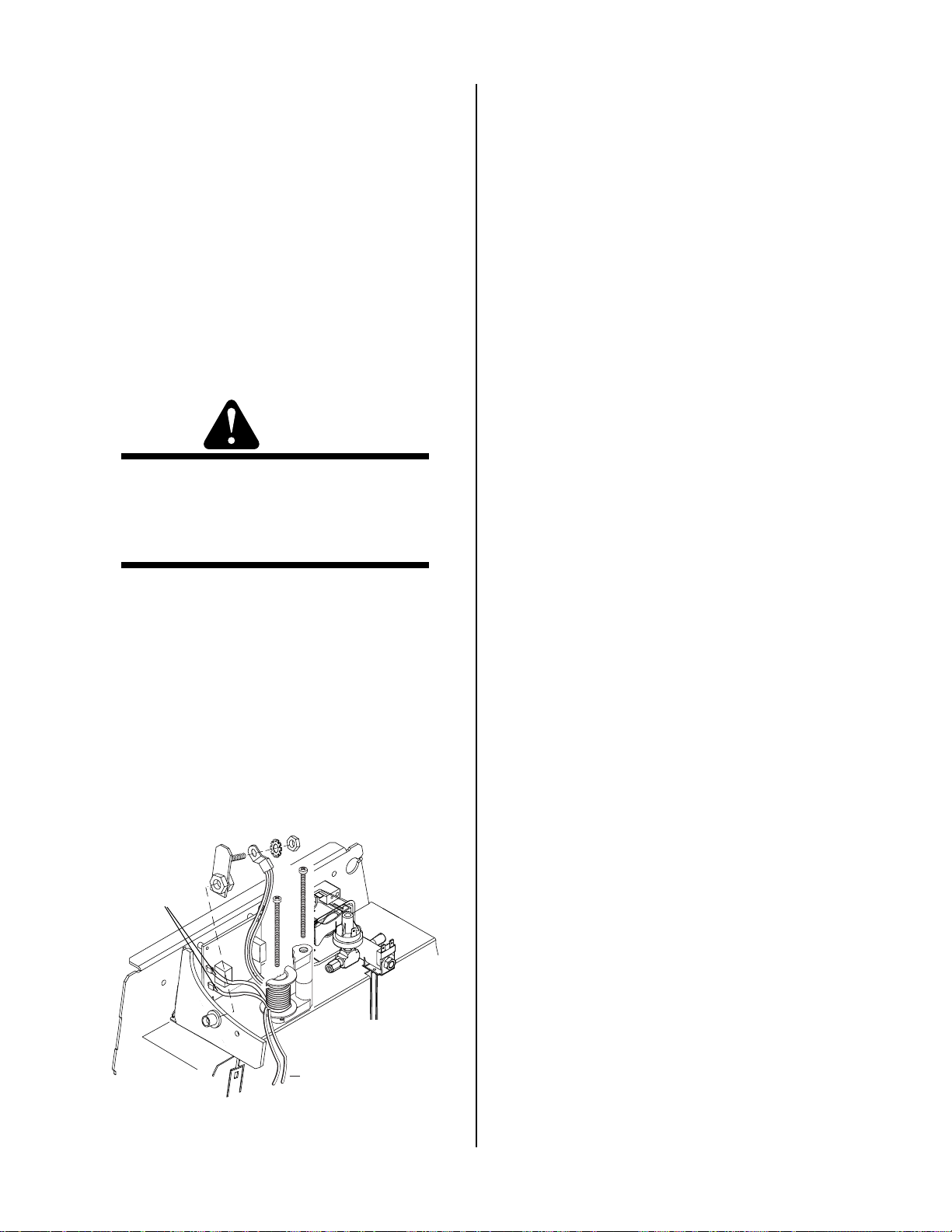
G. CD T ransformer Replacement
H. Heatsink Shroud Assembly Removal
1. Locate the CD PC Board Assembly . Label and disconnect wires E1 and E2. Refer to Appendix 6.
2. Disconnect the transformer wire connected to the
inside of the Power Supply bulkhead.
3. Disconnect the transformer wires connected to E64
on the Power Output PC Board. Refer to Appendix 11.
4. Remove the two long screws securing the Ferrite U-Cores and CD Coil of the CD T ransformer
Assembly to the Heatsink Shroud. Set the Ferrite U- Cores aside.
5. Install the replacement CD T ransformer as follows:
WARNINGS
The Ferrite U-Cores are very brittle and can be
damaged easily if not handled properly.
DO NOT allow the CD T ransformer wires to touch
anything metal.
a. Place the CD T ransformer Assembly in the cor-
rect orientation and install it on the Heatsink
Shroud using the two long bolts.
b. Attach the transformer wire connected to the
inside of the Power Supply bulkhead. Make
sure the wires are not touching anything metal.
c. Connect wires to E1 & E2 on the CD PC Board.
d. Connect the transformer wires to E64 on the
Power Output PC Board. Refer to the follow-
ing illustration:
The Heatsink Shroud Assembly must be disengaged for
access to either the Main Transformer or the Output Inductor. Follow these steps for access to either component.
1. Remove the Power Supply cover per subsection
5.04-A.
2. Release the tab on the Fan Shroud that secures the
Bulkhead in position. Pull the Bulkhead upward
to release the Bulkhead tabs from the slots on the
Center Chassis.
3. Release the tab on the vertical face of the Heatsink
Shroud securing the Solenoid/Pressure Switch Assembly in position.
4. Remove the gas hose from the Regulator Fitting
on the back panel of the Power Supply by pressing on the locking ring on the elbow fitting, while
pulling on the hose.
5. Remove the Power Supply Back Panel per subsection 5.07-D.
6. Remove the grommets from the two holes on the
right (rear) edge of the Heatsink Shroud.
7. Remove the Fan Assembly per subsection 5.08C.
8. Label and disconnect the wires fr om the CD T ransformer to the CD PC Board.
9. Remove the hardware securing the Pilot Control
Relay in place. Pull the Relay and its dust cover
off the center chassis. Set the dust cover aside.
10. Label and disconnect wires No. 45, 49, 47, and 52
from the Power Output PC Board.
11. Disconnect the wires from the Output Inductor to
terminal E43 on the Power Output PC Board.
12. Disconnect the ground wire connected to the center chassis between the Pilot Control Relay and the
Wires to
E1 & E2
CD PC Board.
13. Remove nuts on two studs at the top corners of
the Heatsink Shroud, and nuts on two studs on
the bottom flange of the Heatsink Shroud.
14. Remove the Heatsink Shroud as follows:
a. Use the open left end of the Heatsink Shroud
and the Pressure Switch/Solenoid opening as
Keep wire away
from all metal parts.
handles.
b. Pull the Heatsink Shroud away from the cen-
A-03193
To Power
Output PC
Board
ter chassis, and then up. It may be necessary
to pry the top and bottom flanges of the Heatsink Shroud slightly to release them from their
mounting studs. Movement will be limited by
the wiring harness.
REPAIRS & REPLACEMENT PROCEDURES 5-12 Manual 0-2871
Page 45

c. Ensure that the top edge of the Shroud does
not hit the bottom edge of the CD PC Board.
Stand the Heatsink Shroud Assembly against
the Power Supply.
I. Main Transf ormer Replacement
1. Disengage the Heatsink Shroud per Paragraph H.
2. Disconnect wires #27 and 32, connected to terminals E27 and E32 on the Main Power PC Board.
Pull these wires through the hole in the center chassis.
J. Output Inductor Assembly Replacement
1. Disengage the Heatsink Shroud per paragraph H.
2. Disconnect the wires to the thermal switch on the
Output Inductor .
3. Remove hex nuts at the left forward and right rear
corners of the Inductor base.
4. Remove the Inductor as follows:
a. Note the position of the wires leading from the
Inductor.
3. Remove the Main Transformer as follows:
a. Lift the Main Transformer slightly and swing
the left edge away from the center chassis. Pull
the right edge of the Transformer away from
the center chassis.
b. Lift the Transformer out of the Power Supply
through the opening at the rear of the Power
Supply.
4. Position the replacement Main T ransformer behind
the Heatsink Shroud Assembly. Position its wires
at the right edge (as you face it) of the transformer .
5. Install the replacement transformer as follows:
a. Pass the tabs on the right edge of the base of
the transformer into slots in the center chassis
of the Power Supply.
b. Swing the transformer against the chassis, and
pass the tabs on the left edge of the base into
slots in the chassis. Press the transformer
downward to lock it into position.
c. Check for proper installation; the transformer
should remain securely in place.
b. Lift out the Inductor through the opening at
the rear of the Power Supply. It may be necessary to lift the Main T ransformer slightly to create room for the Inductor to pass through the
rear opening.
5. Install the replacement Inductor.
a. Put the replacement Inductor in place, with the
wires oriented the same way as the original Inductor.
b. Secure the Inductor in place with hex nuts at
opposite corners of the Inductor base.
6. Reconnect the wires to the thermal switch on the
Output Inductor .
7. Replace the Heatsink Shroud per paragraph K.
K. Heatsink Shroud Assembly Replacement
1. Pass transformer wires #45 and 49 through the upper hole in the right (rear) edge of the Heatsink
Shroud. Pass transformer wires #47 and 52
through the lower hole.
2. Route wires as follows:
6.. Pass wires #27 and 32 through the hole in the center of the main chassis. Connect wire #27 to terminal E27 and wire #32 to terminal E32 on the Main
Power PC Board.
7. Replace the Heatsink Shroud Assembly per subsection K.
Manual 0-2871 5-13 REP AIRS & REPLA CEMENT PR OCEDURES
a. Pass the red wires from the output inductor
through the upper hole in the right (rear) edge
of the Heatsink Shroud.
b. Pass the black wires from the output inductor
through the lower hole in the right (rear) edge
of the Heatsink Shroud. Refer to Appendix 1 1,
Power Output Board Layout.
c. Pass the wires from the temperature switch on
the Output Inductor through the upper hole in
the Shroud.
Page 46

3. Re-install the Heatsink Shroud as follows:
a. Lift the Heatsink Shroud (Assembly) into po-
sition. Studs on the Power Supply base pass
through holes in the bottom flange of the
Shroud.
b. Swing the top edge of the Shroud Assembly
into place. Studs on the Center Chassis of the
Power Supply pass through holes in the top
flanges of the Shroud.
c. Ensure that the rubber feet on the Main T rans-
former engage holes in the Shroud.
d. Put hex nuts on the studs. Tighten the nuts on
the right (rear) top and bottom studs. Leave
the nuts on the left (forward) studs loose temporarily.
4. Put the Fan Assembly in place per subsection
5.08-C. Reconnect the work cable to terminal E61
on the Power Output PC Board.
5. T ighten the nuts securing the left edge of the Heatsink Shroud Assembly. The stud and nut on the
bottom left edge fasten a wire stay to the Power
Supply.
6. Replace the grommets around the wire harnesses
passing through the right (rearward) edge of the
Heatsink Shroud.
7. Reconnect the wires to the CD PC Board.
8. Put the Torch Contr ol Bulkhead Panel in position.
Notches on its inner edge engage slots in the center chassis. A tab on the Heatsink Shroud secures
the Bulkhead in place.
9. Reconnect the ground wire to the center chassis,
between the CD PC Board and the Pilot Control
Relay.
10. Replace the Pressure Switch/Solenoid Assembly.
This assembly fits into a slot in the top horizontal
surface of the Heatsink Shroud. A notched pin
holds the assembly in place.
11. Connect the gas hose between the Regulator/Filter Assembly and the Gas Pressure Switch/Solenoid Assembly .
12. Connect wiring to the Output Power PC Board.
Refer to the Appendix pages for wiring layout.
13. Replace the Power Supply rear panel per subsection 5.07-D.
This concludes the replacement procedur es.
REPAIRS & REPLACEMENT PROCEDURES 5-14 Manual 0-2871
Page 47

SECTION 6:
PARTS LISTS
6.01 Introduction
A. Parts List Breakdown
The parts lists provide a breakdown of all replaceable
components. The parts lists are arranged as follows:
Section 6.03 Major External Replacement Parts
Section 6.04 Front Panel Replacement Parts
Section 6.05 Left Side Internal Replacement Parts
Section 6.06 Rear Panel Replacement Parts
Section 6.07 Right Side Internal Replacement Parts
Section 6.08 Options and Accessories
NOTE
Parts listed without item numbers are not shown,
but may be ordered by the catalog number shown.
B. Returns
If a product must be returned for service, contact your
distributor. Materials returned without proper authorization will not be accepted.
6.02 Ordering Information
Order replacement parts by catalog number and complete
description of the part or assembly, as listed in the parts
list for each type item. Also include the model and serial
number of the power supply. Address all inquiries to
your authorized distributor .
Manual 0-2871 6-1 P A RTS LISTS
Page 48
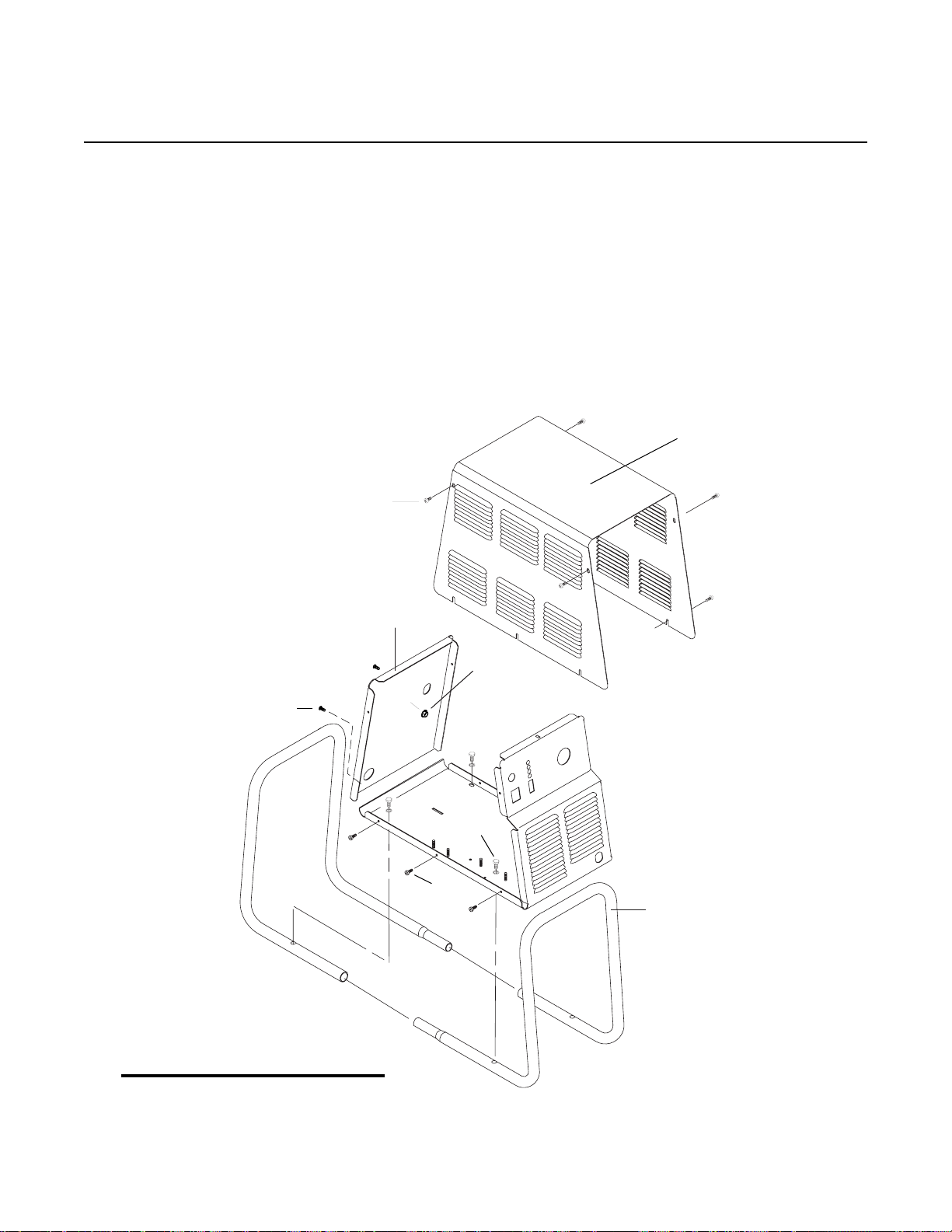
6.03 Major External Replacement Parts
Item # Qty Description Catalog #
1 1 Cover with labels 9-8598-FP
2 1 Rear Panel (Provide data tag information when ordering) 9-8595-FP
3 1 Tube, roll handle 9-8573
Hardware:
A 12 Screw, 10-32 x 1/5" PPH, swageform See Note 1
B 4 Washer, 1/4 External Star See Note 1
C 4 Screw, 1/4-20 x 3/4 Hex head See Note 1
D 1 10-32 kepnut w/ star washer See Note 1
1
A
A
2
D
B, C
A
3
NOTES
A-03374
1. Hardware may be purchased locally.
2. Illustration may vary slightly from unit.
PARTS LISTS 6-2 Manual 0-2871
Page 49
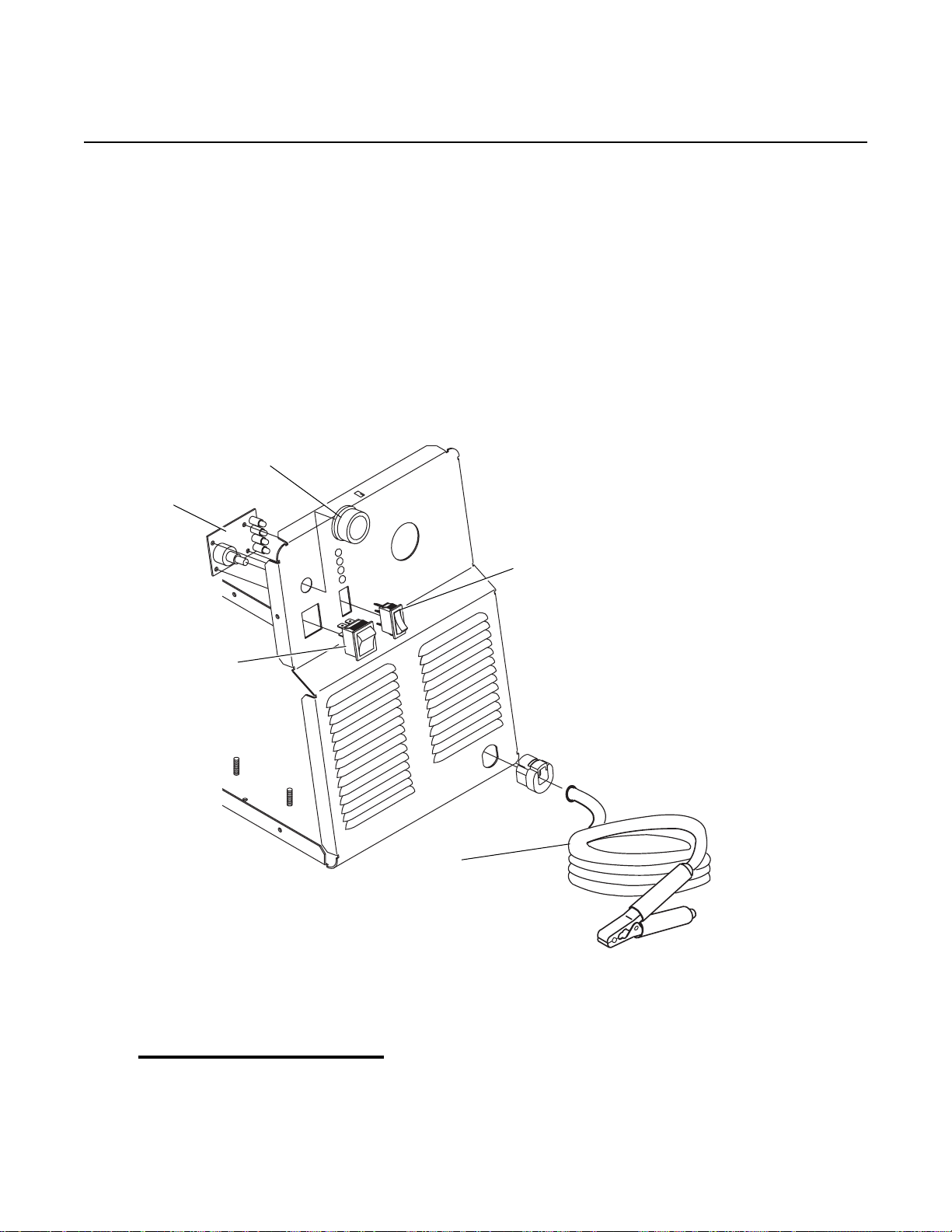
6.04 Front Panel Replacement Parts
Item# Qty Description Ref Catalog #
1 1 Knob, Fluted, Skirted, 0.250 I.D. 9-8527
2 1 On/Off Rocker Switch, DPST SW1 8-3258
3 1 Run/Set Switch, Rocker , SPST, Center Off SW2 9-1042
4 1 Assembly, Pot/LED PCB 9-8004
5 1 Cable, Work, #6 AWG with Clamp, 20 Ft (6.1 m) 9-8528
1
4
2
A-03008
3
5
NOTE
Illustration may vary slightly from unit.
Manual 0-2871 6-3 P A RTS LISTS
Page 50

6.05 Left Side Internal Replacement Parts
Item # Qty Description Ref Catalog #
1 1 Fuse F1 9-8588
2 Main Input Contactor W1 9-8587
3 1 Connector PCB 9-8576
4 1 PCB Assembly, Logic 9-8597
5 1 PCB Assembly Kit, IGBT Circuit 9-8578
Round Thermal Pad
6 1 PCB Assembly Kit, Input Diode 9-8579
Rectangular Thermal Pad
Solid Disk
Round Thermal Pad
7 1 PCB Assembly , Main Power 9-8594
1
7
6
5
5
4
3
2
A-03375
NOTE
Illustration may vary slightly from unit.
PARTS LISTS 6-4 Manual 0-2871
Page 51

6.06 Rear Panel Replacement Par ts
Item # Qty Description Ref Catalog #
1 1 Assembly, Filter/Regulator 9-7514
2 1 Regulator/Filter Replacement Element 9-4414
3 1 Regulator Mounting Bracket 9-7589
4 1 Input Power Cable with plug 9-8596
5 1 Mounting Nut 9-8504
6 1 Pressure Gauge 9-1045
5
3
1
6
4
2
A-03005
NOTE
Illustration may vary slightly from unit.
Manual 0-2871 6-5 P A RTS LISTS
Page 52

6.07 Right Side Internal Replacement Parts
Item # Qty Description Ref Catalog #
1 1 Assembly, Pressure Switch/Solenoid Sol1, PS1 9-8563
2 1 Assembly, CD PC Board 9-8552
3 1 Coil, CD Transformer T10 9-8582
4 1 Pilot Relay PCR 9-8574
5 1 Fan, 220V, 115 CFM M1, M2 9-7687
6 1 Assembly, Main Transformer T5 9-8589
7 1 Assembly, Output Inductor L1 9-8591
8 1 PCB Assembly , Output Power 9-8577
9 1 PCB Assembly Kit, Output Diode 9-8580
Round Thermal Pad
PARTS LISTS 6-6 Manual 0-2871
Page 53

2
5
4
3
7
1
9
6
8
A-03189
Work Cable
Heatsink
Heatsink
Heatsink
Shroud
Fan
Shroud
Bulkhead
5
9
PCR Cover
NOTE
Illustration may vary slightly from unit.
Manual 0-2871 6-7 P A RTS LISTS
Page 54

6.08 Options and Accessories
Qty Description Catalog #
1 Single-Stage Filter Kit (Includes Filter And Hose) 7-7507
1 Replacement Filter Body 9-7740
1 Replacement Filter Element 9-7741
1 Replacement Filter Hose (Not Shown) 9-7742
1 Two-Stage Air Line Filter Kit (Includes Hose & Mounting Screws) 7-7500
1 Bracket, Filter Mounting (Not Shown) 9-7535
1 T wo-Stage Air Filter Assembly 9-7527
1 Replacement First Stage Cartridge 9-1021
1 Replacement Second Stage Cartridge 9-1022
Housing
Filter
Element
Spring
O-ring
Cover
Barbed
Fitting
Assembled Filter
A-02476
Single-Stage Filter Kit Two-Stage Air Filter Kit
First & Second
Stage
Cartridges
(as marked)
A-02942
PARTS LISTS 6-8 Manual 0-2871
Page 55

APPENDIX 1: INPUT WIRING REQUIREMENTS
Firepower 82 Input Wi ring Re qui rements
Input Power Inpu t Curre nt Input Suggested Sizes (See N ote s )
Voltage Freq. 1-Ph 3-Ph 1-Ph 3-Ph Fuse (Amps) Wire (AWG) Wire (Canada)
(Volts) (Hz) (kVA) (kVA) (Amps) (Amps) 1-Ph 3-Ph 1-Ph 3-Ph 1-Ph 3-Ph
208 50/60 11.8 57 60 6 6
230 50/60 11.8 52 60 6 6
Line Voltages with Suggested Circuit Protection and Wire Sizes
Based on National Electric Code and Canadian Electrical Code
NOTES
Refer to Local and National Codes or local authority having jurisdiction for proper wiring requirements.
Cable size is de-rated based on the Duty Cycle of the equipment.
The suggested sizes are based on flexible power cable with power plug installations. For hard-wired installations
refer to local or national codes.
Cable conductor temperature used is 167° F (75° C).
An energy limiting fuse UL Class RK-1 (examples: BUSS LPS/LPN-RK or Gould-Shawmut AZK-A6K) should be
used to minimize damage to Plasma Cutting, Welding or power distribution equipment.
NEVER use replaceable element fuses like UL Class H, or "one-time" fuses like UL Class K5.
Manual 0-2871 A-1 APPENDIX
Page 56

APPENDIX 2: SEQUENCE OF OPERATION
(BLOCK DIAGRAM)
ACTION
Close external
disconnect switch.
RESULT
Power to system.
ACTION
Protect eyes and
activate torch.
RESULT
Gas flows (2 seconds).
After gas pre-flow:
DC indicator on.
Pilot relay closes.
Pilot arc established
ACTION
ON/OFF switch
to ON.
RESULT
AC indicator blinks for 8
seconds then steady on.
Fans on.
Power circuit ready.
gas flows to set pressure.
PILOT ARC
ACTION
RUN/SET switch
to SET.
RESULT
Gas solenoid open,
GAS indicator on.
ACTION
RUN/SET
switch to RUN.
RESULT
Gas flow stops.
GAS indicator off.
ACTION
Torch moved away
from work (while
still activated).
RESULT
Main arc stops.
Pilot arc automatically
restarts.
ACTION
Torch deactivated (by torch switch
release or by remote device).
RESULT
(Power supply enable signal removed)
post-flow, pilot arc will immediately restart.
(1/4 in/6.4mm) of workpiece, main arc
Gas solenoid closes, gas flow stops.
Main arc stops.
Gas flows (10 seconds)
NOTE - If torch is activated during
If torch is within transfer distance
will transfer.
After post-flow:
GAS indicator off.
ACTION
ON/OFF switch
to OFF
RESULT
All indicators off.
Power supply fans off.
ACTION
Torch moved within
transfer distance of workpiece.
RESULT
Main arc transfer.
Pilot arc off.
ACTION
Open external
disconnect.
RESULT
No power to system.
A-02778
APPENDIX A-2 Manual 0-2871
Page 57

APPENDIX 3: LOGIC PC BOARD LAYOUT
D20
D21
TP3
TP12
TP2
TP1
TP9
D32
D37
TP4
TP8
TP5
TP6
Logic Board Signals
P1-1 +12 vdc from Main PCB
P1-2 +12 vdc from Main PCB
P1-3 DC Common
P1-4 DC Common
P1-5 W1 ON Signal
P1-6 Tip Sense
P1-7 RUN/SET signal logic low for SET
P1-8 Pressure good signal (Logic low)
P1-9 OVERTEMP signal (Logic low)
P1-10 Inrush done signal from Main PCB
P1-11 CD Enable signal from Main PCB
P1-12 CD Enable signal from Main PCB
P1-13 Open
P1-14 Gas ON signal to Main PCB
P1-15 Logic low CSR signal
P1-16 Logic low PILOT ON signal
P1-17 Logic low DC OK signal
P1-18 Logic low OVERTEMP signal
P1-19 Logic low AC OK signal
P1-20 Return for torch switch
P1-21 Logic low = torch switch signal
P1-22 +12 vdc
P1-23 to curr ent control pot
P1-24 Current contr ol
P1-25 Current control return
P1-26 Gate drive B return
TP7
TP10
P1-27 Gate drive B signal
P1-28 Gate drive A return
P1-29 Gate drive A signal
P1-30 (-) out signal
P1-31 Current sense
P1-32 Current sense
P1-33 Current sense return
P1-34 Current sense return
P1-35 DC Common
P1-36 DC Common
TP-1 Common
TP-2 CSR (Logic low)
TP-3 Converter enable
TP-4 Gate Drive B
TP-5 Demand Signal
TP-6 Output voltage sense
TP-7 DC ok (Logic low)
TP-8 Gate Drive A
TP-9 Fault (Logic low)
TP-10 T ip sense
Indicators:
D20 CD ON
D21 INV ON
D32 SW ON
D37 DRAG ON
A-03156
Manual 0-2871 A-3 APPENDIX
Page 58

APPENDIX 4: MAIN POWER PC BOARD LAYOUT
E22
E1
E2
E3
E15
E7
J25
E10
J30
J11
J15
Fuse
LT1
J17 TP4
INPUT
DIODE
J16
TP6
J23
J24
J32
J29
J33
J18
J43
J27
E32
J26
E27
E30
J31
E20
IGBT A
Main Power PC Board Signals
J11-1 L1 Input
J11-2 Not Used
J11-3 Not Used
J11-4 L3 Input
J15-1 Fan (M1)
J15-2 Fan (M1)
J15-3 Not Used
J15-4 Not Used
J15-5 Fan (M2)
J15-6 Fan (M2)
J16-1 Not Used
J16-2 Not Used
E33 E4
E23
IGBT B
J18-1 PCR
J18-2 PCR
J18-3 28VAC B
J18-4 28V AC A
J18-5 On-Off Switch
J18-6 On-Off Switch
J18-7 Run-Set Switch
J18-8 Run-Set Switch
A-03149
J17-1 Not Used
J17-2 Not Used
APPENDIX A-4 Manual 0-2871
Page 59

J23-1 Not Used
J23-1 Not Used
J23-3 Not Used
J24-1 Gas Solenoid
J24-2 Gas Solenoid
J24-3 Pressure Switch
J24-4 Pressure Switch
J24-5 Main Contactor
J24-6 Main Contactor
J24-7 Not Used
J24-8 Not Used
J25-1 Gate Drive
J25-2 Gate Drive
J26-1 Gate Drive
J26-2 Gate Drive
J27-1 Pot High
J27-2 Pot Wiper
J27-3 Pot Low
J27-4 +12vdc
J27-5 AC
J27-6 Gas
J27-7 Over Temp
J27-8 DC
J29-1 IGBT Heatsink Temp
J29-2 IGBT Heatsink Temp
J29-3 Jumper
J29-4 Jumper
J30-1 Gate Drive
J30-2 Gate Drive
J31-1 Gate Drive
J31-2 Gate Drive
J32-1 Inductor Temp Switch
J32-2 Inductor Temp Switch
J43-1 +12vdc
J43-2 +12vdc
J43-3 DC Com
J43-4 DC Com
J43-5 MC1 On
J43-6 Tip Sense
J43-7 Run/Set
J43-8 Press Good
J43-9 Over Temp
J43-10 Inrush Done
J43-11 CD Enable
J43-12 CD Enable
J43-13 (Open?)
J43-14 Gas On
J43-15 CSR
J43-16 Pilot On
J43-17 DC Ok
J43-18 OV Temp
J43-19 AC Ok
J43-20 Torch Switch Return
J43-21 Torch Switch
J43-22 +12vdc
J43-23 Pot High
J43-24 Pot Wiper
J43-25 Pot Low
J43-26 Gate Drive B Return
J43-27 Gate Drive B
J43-28 Gate Drive A Return
J43-29 Gate Drive A
J43-30 - Out
J43-31 Current Sense
J43-32 Current Sense
J43-33 Current Sense Return
J43-34 Current Sense Return
J43-35 DC Com
J43-36 DC Com
TP-4 +12 vdc
TP-6 Common
J33-1 - Out
J33-2 DC Com
J33-3 Tip Sense
J33-4 +12vdc
J33-5 CSR
J33-6 Tor ch Switch
J33-7 Tor ch Switch Return
J33-8 CD Enable
Manual 0-2871 A-5 APPENDIX
Page 60
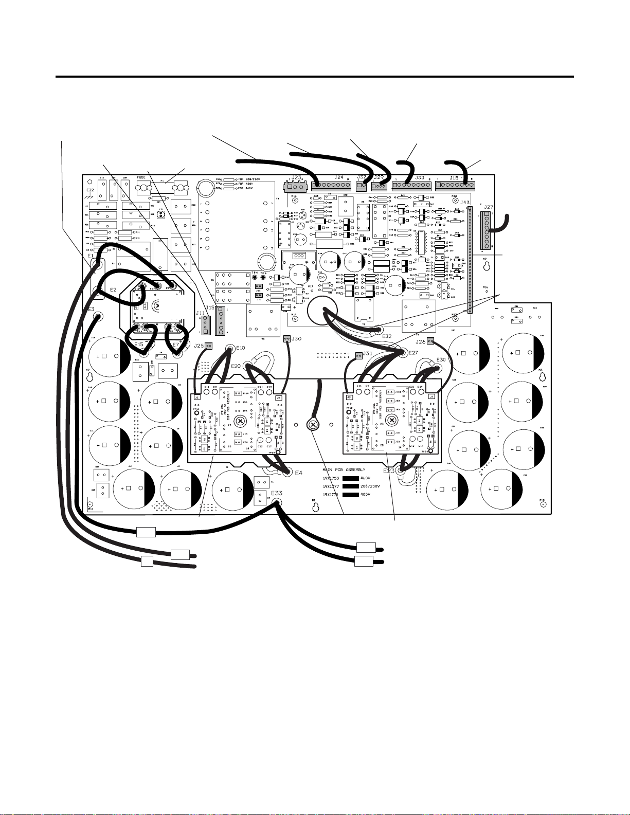
APPENDIX 5: MAIN PC BOARD WIRING
Copper
Strap
To Main Input
Contactor
To Fans
To Press Sw/
Solenoid/
Contactor
Fuse
Input
Diode
To Inductor
Temp Switch
Secondary
Transformer
To HeatSink T emp
Switch
To Power Output Board
To PCR/On-Off Switch/
Run-Set Switch
To Pot/LED PCB
To Logic PCB
via Extender
To Main
Transformer
Heatsink
Temp Switch
#2
#3
IGBT B
To Main Input
{
Contactor
A-03187
#33
#1
IGBT A
#78
{
To Main Input
Contactor
APPENDIX A-6 Manual 0-2871
Page 61

APPENDIX 6: CD PC BOARD LAYOUT
E1
E2
CD PC Board Signals
J28-1 +12 vdc
J28-2 CD Enable
J28-3 Not Used
J28-4 Not Used
J28-5 E47
J28-6 Not Used
J28-7 Not Used
J28-8 E45
J28
8
A-03086
Manual 0-2871 A-7 APPENDIX
Page 62

APPENDIX 7: LED/POT PC BOARD LAYOUT
J14
D4
D5
D7
A-01206
Pot/LED PC Board Signals
J14-1 +10 vdc from Logic PC Board (J27-1) Pot High
J14-2 Current Controlto Logic PC Board (J27-2) Pot Wiper
J14-3 Return for Current Control from Logic PC Board (J27-3) Pot Low
J14-4 12vdc (J27-4)
J14-5 Logic Low Signal for AC OK Indicator from Logic PC Board (J27-5)
J14-6 Logic Low Signal for GAS Indicator from Logic PC Board (J27-6)
J14-7 Logic Low Signal for TEMP Indicator from Logic PC Board (J27-7)
J14-8 Logic Low Signal for DC Indicator from Logic PC Board (J27-8)
D4 Front Panel AC Indicator
D5 Front Panel TEMP Indicator
D6 Front Panel DC Indicator
D7 Front Panel GAS Indicator
D6
APPENDIX A-8 Manual 0-2871
Page 63

APPENDIX 8: IGBT CIRCUIT PC BOARD LAYOUT
J3
TP1A
E11
E9
IGBT A
E21 E19
E12
E17
J7
TP2A
J3
TP1B
E11
E9
IGBT B
E21
E12
E19
J7
TP2B
E17
A-03154
Manual 0-2871 A-9 APPENDIX
Page 64

APPENDIX 9: INPUT DIODE PC BOARD LAYOUT
E13
E18
E5
E14
NOTE:
Refer to Appendix 5 for wiring connections.
E16
E6
E8
A-03155
APPENDIX A-10 Manual 0-2871
Page 65

APPENDIX 10: OUTPUT DIODE PC BOARD LAYOUT
Output Diode A
E34
E39
E60
E56
Output Diode B
E48
E50
E54
E53
A-03152
NOTE:
Refer to Appendix 11 for wiring connections.
Manual 0-2871 A-11 APPENDIX
Page 66
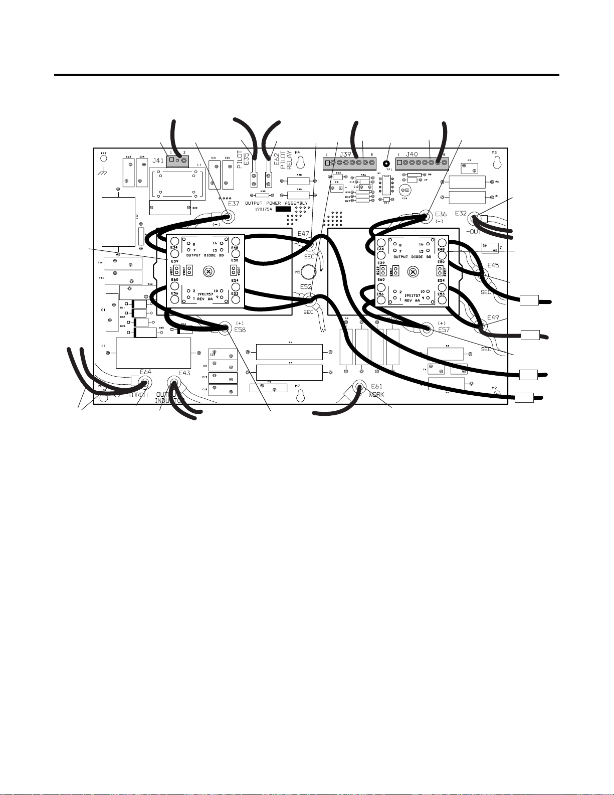
APPENDIX 11: POWER OUTPUT PCB WIRING DIAGRAM
Output
Diode A
T o Torch Switch
J41
E37
To Bulkhead
E35 E62
To PCR
E47
E52
To Main Power
PC Board
TP1
J39
To CD PCB
J40
E36
E32
To Output
Inductor
Output
Diode B
E45
#45
E49
#49
E57
#47
To CD Coil
E64
E43
To Output
Inductor
Power Output PC Board Signals
J39-1 - Out
J39-2 DC Com
J39-3 Tip Sense
J39-4 +12vdc
J39-5 CSR
J39-6 Torch Switch
J39-7 Torch Switch Return
J39-8 DC Enable
J40-1 +12vdc
J40-2 CD Enable
J40-3 Not Used
J40-4 Not Used
J40-5 E47
J40-6 Not Used
J40-7 Not Used
J40-8 E45
E58
Work Cable
J41-1 Torch Switch
J41-2 Not Used
J41-3 Torch Switch
E61
#52
A-03153
APPENDIX A-12 Manual 0-2871
Page 67

APPENDIX 12: 28VAC CIRCUIT DIAGRAM
Line V oltage
J24
SOL
1 2 5 6
W1
Auxiliary
Transformer
Fuse
primary
J81
J11
4
J18
secondary
3 4 5 6
K5
K4
Voltage
Protection
J23
2
3
+12vdc
1
ON/OFF Switch
Main Power PC Board
A-03071
Manual 0-2871 A-13 APPENDIX
Page 68

APPENDIX 13: MAINTENANCE SCHEDULE
This schedule applies to all types of non-liquid cooled plasma cutting systems. Some systems will not have all the
parts listed and those checks need not be performed.
NOTE
The actual frequency of maintenance may need to be adjusted according to the operating environment.
Daily Operational Checks or Every Six Cutting Hours:
1. Check torch consumable parts, replace if damaged or worn.
2. Inspect torch for any cracks or exposed wires, replace if necessary.
3. Check plasma and secondary supply and pressure/flow.
4. Purge plasma gas line to remove any moisture build-up.
5. Inspect input power cable for damage or exposed wires, replace if necessary.
Weekly or Every 30 Cutting Hours:
1. Check fan for proper operation and adequate air flow.
2. Blow or vacuum dust and dirt out of the entire machine.
CAUTION
Do not blow air into the power supply during cleaning. Blowing air into the unit can cause metal particles to
interfere with sensitive electrical components and cause damage to the unit.
Six Months or Every 720 Cutting Hours:
1. Check the in-line air filter(s), clean or replace as required
2. Check cables and hoses for leaks or cracks, replace if necessary.
3. Check all contactor points for severe arcing or pits, replace if necessary.
APPENDIX A-14 Manual 0-2871
Page 69

Manual 0-2871 A-15 APPENDIX
Page 70

APPENDIX 14: SYSTEM SCHEMATIC
A
B
C
D
E
F
208/230V
SINGLE PHASE
INPUT
M2
FAN2
M1
FAN1
PILOT RELAY
PCR
28VAC B
28VAC A
ON/OFF SW
SW1
R
RUN/SET SW
SW2
CW
CURRENT
CONTROL
LED PCB
19X1604
CURRENT ADJUST
20 - 60
IGBT HEATSINK
INDUCTOR TEMP
1
NTC
S
TEMP
TS1
AC
TEMP
2
W1
L1
W1
L2
(2)
W1
L3
(3)
W1
L4
230V
J15
P15
(6)
6
6
(6)
5
5
(7)
2
2
(7)
1
1
J18
P18
(19)
1
1
(20)
2
2
(21)
3
3
(22)
4
4
(23)
5
5
(24)
6
6
(25)
7
7
(26)
8
8
P27
(35)
(36)
(37)
(38)
(39)
(40)
(41)
(42)
J27
1
1
2
2
3
3
4
4
5
5
6
6
7
7
8
8
J29
P29
1
1
2
2
3
3
4
4
J32
P32
1
1
2
2
J14
1
2
3
4
5
6
7
8
GAS
DC
t
TS2
COPPER
STRAP
CHASSIS
GND
(4)
(5)
(1)
(78)
(33)
P11
E1
E2
E3
E33
E22
J11
1
1
4
4
K2
POT HIGH
POT WIPER
POT LOW
+12V
AC
GAS
OVERTEMP
DC
+18V
FILTERING
600V, 6/10A, KTK
PILOT ON
1
2
J23
TEST CONNECTOR
K4
(8)
SOL1
A
GAS SOLENOID
R30
ZERO
FOR 230V
ONLY
3
FUSE
J24
P24
B
F1
0.9A
E13
E18
F2
1
(9)
LT1
1
PRESSURE SW
INPUT DIODE
ASSEMBLY 19X1755
1 2
6
460V
5
400V
3
230V
1
RESETABLE
2
3
4
6
5
6
4
3
5
2
(12)
(11)(10)
PS1
3
K1
T1
K5
PRESS GOOD
7
8
8
7
MAIN CONTACTOR
(13)
7
9
10
12
W1
E6
E8
E14
E16
INRUSH
K1
28VAC A
TO BIAS SUPPLY
28VAC B
4
E7
E5
E15
K1
+12VDC
+18V
FAN
K2
+18VDC
+18VDC
SOLENOID ON RELAY
CONTACTOR ON RELAY
MAIN BOARD ASSEMBLY 19X1777
CD ON
INV ON
DRAG ON
SW ON
LOGIC BOARD
ASSEMBLY 19X1784
D20
D21
D37
D32
E4
E20
E23
E30
K4
K5
P1
J13
1
1
2
2
3
3
4
4
5
5
6
6
7
7
8
8
9
9
10
10
11
11
12
12
13
13
14
14
15
15
16
16
17
17
18
18
19
19
20
20
21
21
22
22
23
23
24
24
25
25
26
26
27
27
28
28
29
29
30
30
31
31
32
32
33
33
34
34
35
35
36
36
IGBT PCB ASSEMBLY 19X1756
E12A
E17A
24
25
E19A
E21A
IGBT PCB ASSEMBLY 19X1756
E12B
E17B
24
25
E19B
E21B
+12VDC
+12VDC
DC COM
DC COM
MC1ON
TIP SENSE
RUN/SET
PRESS GOOD
OVERTEMP
INRUSH DONE
CD ENABLE
CD ENABLE
GAS ON
PILOT ON
DC OK
OVTEMP
AC OK
TORCH SW RTN
TORCH SW
+12VDC
POT HIGH
POT WIPER
POT LOW
GATE DRIVE B RTN
GATE DRIVE B
GATE DRIVE A RTN
GATE DRIVE A
CURRENT SENSE
CURRENT SENSE
CURRENT SENSE RTN
CURRENT SENSE RTN
EXTENDER BOARD
ASSEMBLY 19X1775
DC COM
DC COM
-OUT
5
GATE
12231314
DRIVE
28
27
GATE
DRIVE
1
24567
GATE
12231314
DRIVE
28
27
GATE
DRIVE
1
24567
J43
J12
1
1
2
2
3
3
4
4
5
5
6
6
7
7
8
8
9
9
1010
11
11
12
12
13
13
14
14
15
CSR
15
16
16
17
17
18
18
19
19
20
20
21
21
22
22
23
23
24
24
25
25
26
26
27
27
28
28
29
29
30
30
31
31
32
32
33
33
34
34
35
35
36
36
A-03221
1
2
3
4
5
APPENDIX A-16 Manual 0-2871
Page 71

E11A
E11B
6
P25J25
1
212
P3A
J3A
1
1
2
2
E9A
J7A
J3B
E9B
J7B
E32
P7A
E10
1
1
2
2
P3B
1
1
2
2
P7B
1
1
2
2
1
J30 P30
212
1
J31 P31
212
E27
P26J26
1
212
TIP SENSE
TORCH SW
TORCH SW RTN
CD ENABLE
-OUT
DC COM
+12VDC
CSR
MAIN
T5
PRI
PRI
P33
J33
(70)
1
1
(71)
2
2
(72)
3
3
(73)
4
4
(74)
5
5
(75)
6
6
(76)
7
7
(77)
8
8
SEC
SEC
7
OUTPUT DIODE
ASSEMBLY
19X1757
E50B
E45
E48B
E49
E53B
E54B
OUTPUT DIODE
ASSEMBLY
19X1757
E50A
E47
E48A
E52
E53A
E54A
P39
J39
1
1
2
2
3
3
4
4
5
5
6
6
7
7
8
8
8
E34B
POWER OUTPUT BOARD
ASSEMBLY 19X1754
E39B
E56B
E60B
E34A
E39A
E56A
E60A
E36
E57
E37
E58
+12VDC
CD ENABLE
E47
E45
CURRENT SENSE
DC COM
9
E32
E62
E35
E43
E64
E63
J40
1
2
3
4
5
6
7
8
E61
J41
3
2
1
OUTPUT INDUCTOR
PILOT
THRU SCREW TERMINAL
CHASSIS GND
CD ASSEMBLY
19X1751
P40
(14)
1
(15)
2
3
4
(17)
5
6
7
(18)
8
P41
(30)
3
2
(31)
1
L1
E(62)
E(35)
J28
2
E(58)
J42
3
4
13
10
A
B
PCR
T10
CD
581
T
O
R
C
H
WORK
C
D
(30)
TORCH
SWITCH
(31)
COMP DESCRIPTION LOCATION
F1
F2
L1
M1
M2
PCR
PS1 PRESSURE SWITCH
SOL1 GAS SOLENOID
SW1
SW2
T5
T10 CD TRANSFORMER C10
TS1
TS2
W1
6
7
FUSE, 6/10A 600V , KTK
FUSE, 0.9A, RESETABLE
OUTPUT INDUCTOR A10
FAN, 4.5" 220VAC
FAN, 4.5" 220VAC
PILOT RELAY
SWITCH, ON/OFF
SWITCH, RUN/SET
MAIN TRANSFORMER
TEMP. SENSOR, IGBT HEATSINK
TEMP. SENSOR, INDUCTOR
MAIN CONTACTOR F3,A2
DateByRevisionsRev
RELEASE ECO 3A16
AA
Last Modified:
Tuesday, August 21, 2001
GCW 08/21/01
15:05:29
8
B2
E3
C1
B1
C1
F3
F2
C1
D1
B7
E1
F1
THERMAL DYNAMICS
INDUSTRIAL PARK No. 2
WEST LEBANON, NH 03784
Information Proprietary to THERMAL DYNAMICS CORPORATION.
Not For Release, Reproduction, or Distribution without Written Consent.
NOTE:
Unless Otherwise Specified, Resistors are in Ohms 1/4W 5%.
Capacitors are in Microfarads (UF) Chk: App:
TITLE:
CM75 208/230V SINGLE PHASE 50/60 Hz
SCHEMATIC,
603-298-5711
9
PCB No:
Assy No:
SupersedesScale
Date:
Tuesday, May 15, 2001
Drawn: References
GCW
Sheet
11
of
DWG No:
Size
42X1096
C
10
A-03221
E
F
Manual 0-2871 A-17 APPENDIX
Page 72

 Loading...