

Page 1

®
Firepower
FP 125, FP 135, FP165
PORTABLE MIG/FLUX CORED WELDER
Operating
Manual
Révision : AC Issue Date: April 6, 2016 Manual No.: 0-5123
www.firepoweronline.com
Page 2

WE APPRECIATE YOUR BUSINESS!
Congratulations on your new Firepower product. We are proud to have you as our customer and will strive
to provide you with the best service and reliability in the industry. This product is backed by our extensive
warranty and world-wide service network. To locate your nearest distributor or service agency, visit us on
the web at www.firepoweronline.com.
This Operating Manual has been designed to instruct you on the correct use and operation of your Firepower
product. Your satisfaction with this product and its safe operation is our ultimate concern. Therefore please
take the time to read the entire manual, especially the Safety Precautions. They will help you to avoid potential
hazards that may exist when working with this product.
YOU ARE IN GOOD COMPANY!
The Brand of Choice for Contractors and Fabricators Worldwide.
ESAB is a Global Brand of manual and automation Plasma Cutting Products.
We distinguish ourselves from our competition through market-leading, dependable products that have stood
the test of time. We pride ourselves on technical innovation, competitive prices, excellent delivery, superior
customer service and technical support, together with excellence in sales and marketing expertise.
Above all, we are committed to developing technologically advanced products to achieve a safer working
environment within the welding industry.
Page 3

WARNING
!
Firepower FP 125, 135, 165 MIG/Flux Cored Welder
Operating Manual Number 0-5123
Published by:
ESAB
2800 Airport Rd.
Denton, TX 76208
www.Firepoweronline.com
Copyright 2015 by ESAB
All rights reserved.
Reproduction of this work, in whole or in part, without written permission of the publisher
is prohibited.
Read and understand this entire Manual and your employer’s safety practices before installing, operating, or servicing the equipment.
While the information contained in this Manual represents the Manufacturer's best judgement,
the Manufacturer assumes no liability for its use.
The publisher does not assume and hereby disclaims any liability to any party for any loss
or damage caused by any error or omission in this Manual, whether such error results from
negligence, accident, or any other cause.
For Printing Material Specification refer to document 47x1909
Original Publication Date: March 19, 2009
Revision Date: April 6, 2016
Record the following information for Warranty purposes:
Where Purchased:_______________________________ __________
Purchase Date:__________________________________ __________
Power Supply Serial #:___________________________ __________
Torch Serial #:___________________________________ __________
Page 4
Be sure this information reaches the operator.
You can get extra copies through your supplier.
CAUTION
These INSTRUCTIONS are for experienced operators. If you are not fully familiar
with the principles of operation and safe practices for arc welding and cutting equipment, we urge you to read our booklet, “Precautions and Safe Practices for Arc
Welding, Cutting, and Gouging,” Form 52-529. Do NOT permit untrained persons to
install, operate, or maintain this equipment. Do NOT attempt to install or operate this
equipment until you have read and fully understand these instructions. If you do not
fully understand these instructions, contact your supplier for further information. Be
sure to read the Safety Precautions before installing or operating this equipment.
USER RESPONSIBILITY
This equipment will perform in conformity with the description thereof contained in this manual and accompanying labels and/or inserts when installed, operated, maintained and repaired in accordance with the instructions
provided. This equipment must be checked periodically. Malfunctioning or poorly maintained equipment should not be
used. Parts that are broken, missing, worn, distorted or contaminated should be replaced immediately. Should such repair or replacement become necessary, the manufacturer recommends that a telephone or written request for service
advice be made to the Authorized Distributor from whom it was purchased.
This equipment or any of its parts should not be altered without the prior written approval of the manufacturer.
The user of this equipment shall have the sole responsibility for any malfunction which results from improper use,
faulty maintenance, damage, improper repair or alteration by anyone other than the manufacturer or a service facility
designated by the manufacturer.
READ AND UNDERSTAND THE INSTRUCTION MANUAL BEFORE INSTALLING OR
PROTECT YOURSELF AND OTHERS!
!
OPERATING.
Page 5

TABLE OF CONTENTS
SECTION 1: SAFETY ........................................................................................ 1-1
1.0 Safety Precautions .......................................................................................... 1-1
2.0 Précautions de sécurité .................................................................................. 1-3
SECTION 2:
INTRODUCTION ...................................................................................... 2-1
2.01 How To Use This Manual ................................................................................ 2-1
2.02 Equipment Identification ................................................................................. 2-1
2.03 Receipt Of Equipment ..................................................................................... 2-1
2.04 General ........................................................................................................... 2-1
2.05 Specifications ................................................................................................. 2-2
2.06 Volt - Amp Curves .......................................................................................... 2-3
2.07 Duty Cycle ...................................................................................................... 2-5
2.08 MIG Gun Maintenance ................................................................................... 2-6
2.09 Handle / Feet Assembly ................................................................................... 2-6
SECTION 3:
INSTALLATION ....................................................................................... 3-1
3.01 Location ......................................................................................................... 3-1
3.02 Safety ............................................................................................................. 3-1
3.03 Grounding ...................................................................................................... 3-1
3.04 Electrical Input Requirements ........................................................................ 3-1
3.05 Requirements for Maximum Output .............................................................. 3-1
3.06 Installation of Shielding Gas (GMAW) Process .............................................. 3-2
3.07 Attaching the Gun and Cable Assembly to the Power Source ........................ 3-5
3.08 Polarity Changeover ....................................................................................... 3-6
3.09 Installing Wire Spool ..................................................................................... 3-7
3.10 Feedrolls ......................................................................................................... 3-7
3.11 Install Wire into the Feedhead ........................................................................ 3-7
3.12 Install Wire into the Welding Gun .................................................................. 3-9
SECTION 4:
OPERATION ........................................................................................... 4-1
4.01 General Safety Precautions ............................................................................. 4-1
4.02 Firepower Controls ........................................................................................ 4-1
4.03 Gas Metal Arc Welding (GMAW) .................................................................... 4-3
4.04 Flux Cored Arc Welding (FCAW) .................................................................... 4-3
4.05 Shutdown Procedures .................................................................................... 4-3
4.06 Basic Welding Technique ............................................................................... 4-3
4.07 Welding Gun Positions .................................................................................. 4-5
4.08 MIG Welding (GMAW) Variables .................................................................... 4-6
4.09 Establishing the Arc and Making Weld Beads ................................................ 4-7
4.10 Pre-Weld Procedure ....................................................................................... 4-7
4.11 Welding Procedure ........................................................................................ 4-7
4.12 Reference Tables ............................................................................................ 4-8
4.13 Firepower FP 125 Welding Setting Selection Guide ........................................ 4-9
4.14 Firepower FP 135 Welding Setting Selection Guide ...................................... 4-10
Page 6

TABLE OF CONTENTS
4.15 Firepower FP 165 Welding Setting Selection Guide ...................................... 4-11
4.16 Gas Selection for Gas Metal Arc Welding ...................................................... 4-12
SECTION 5:
SERVICE ............................................................................................... 5-1
5.01 Cleaning of the Unit ....................................................................................... 5-1
5.02 Cleaning of the Feed Rolls ............................................................................. 5-1
5.03 Basic Troubleshooting ................................................................................... 5-1
5.04 Solving Problems Beyond the Welding Terminals .......................................... 5-1
5.05 Welding Problems ......................................................................................... 5-2
APPENDIX 1: OPTIONS AND ACCESSORIES ............................................................ A-1
APPENDIX 2: REPLACEMENT PARTS ................................................................... A-2
APPENDIX 3: FIREPOWER 125 SYSTEM SCHEMATIC ................................................. A-4
APPENDIX 4: FIREPOWER 135 SYSTEM SCHEMATIC ................................................. A-5
APPENDIX 5: FIREPOWER 165 SYSTEM SCHEMATIC ................................................. A-6
REVISION HISTORY ........................................................................................ A-8
INTERNATIONAL CONTACT INFORMATION ................................................. REAR COVER
Page 7

FIREPOWER FP 125,135,165
SECTION 1: SAFETY
1.0 Safety Precautions
Users of ESAB welding and plasma cutting equipment have the ultimate responsibility for ensuring that anyone who works
on or near the equipment observes all the relevant safety precautions. Safety precautions must meet the requirements that
apply to this type of welding or plasma cutting equipment. The following recommendations should be observed in addition to
the standard regulations that apply to the workplace.
All work must be carried out by trained personnel well acquainted with the operation of the welding or plasma cutting
equipment. Incorrect operation of the equipment may lead to hazardous situations which can result in injury to the operator
and damage to the equipment.
1. Anyone who uses welding or plasma cutting equipment must be familiar with:
- its operation
- location of emergency stops
- its function
- relevant safety precautions
- welding and / or plasma cutting
2. The operator must ensure that:
- no unauthorized person stationed within the working area of the equipment when it is started up.
- no one is unprotected when the arc is struck.
3. The workplace must:
- be suitable for the purpose
- be free from drafts
4. Personal safety equipment:
- Always wear recommended personal safety equipment, such as safety glasses, flame proof
clothing, safety gloves.
- Do not wear loose fitting items, such as scarves, bracelets, rings, etc., which could become
trapped or cause burns.
5. General precautions:
- Make sure the return cable is connected securely.
- Work on high voltage equipment may only be carried out by a qualified electrician.
- Appropriate fire extinguishing equipment must be clearly marked and close at hand.
- Lubrication and maintenance must not be carried out on the equipment during operation.
Dispose of electronic equipment at the recycling facility!
In observance of European Directive 2002/96/EC on Waste Electrical and Electronic Equipment and its
implementation in accordance with national law, electrical and/or electronic equipment that has reached
the end of its life must be disposed of at a recycling facility.
As the person responsible for the equipment, it is your responsibility to obtain information on approved
collection stations.
For further information contact the nearest ESAB dealer.
ESAB can provide you with all necessary cutting protection and accessories.
Manual 0-5123 1-1 SAFETY INSTRUCTIONS
Page 8

FIREPOWER FP 125,135,165
WARNING
ELECTRIC SHOCK - Can kill.
- Install and earth (ground) the welding or plasma cutting unit in accordance with applicable standards.
- Do not touch live electrical parts or electrodes with bare skin, wet gloves or wet clothing.
- Insulate yourself from earth and the workpiece.
- Ensure your working stance is safe.
FUMES AND GASES - Can be dangerous to health.
- Keep your head out of the fumes.
- Use ventilation, extraction at the arc, or both, to take fumes and gases away from your
breathing zone and the general area.
ARC R AYS - Can injure eyes and burn skin.
- Protect your eyes and body. Use the correct welding / plasma cutting screen and filter
lens and wear protective clothing.
- Protect bystanders with suitable screens or curtains.
FIRE HAZARD
- Sparks (spatter) can cause fire. Make sure therefore that there are no inflammable materials nearby.
Arc welding and cutting can be injurious to yourself and others. Take
precautions when welding and cutting. Ask for your employer's safety
practices which should be based on manufacturers' hazard data.
NOISE - Excessive noise can damage hearing.
- Protect your ears. Use earmuffs or other hearing protection.
- Warn bystanders of the risk.
MALFUNCTION - Call for expert assistance in the event of malfunction.
READ AND UNDERSTAND THE INSTRUCTION MANUAL BEFORE INSTALLING OR OPERATING.
PROTECT YOURSELF AND OTHERS!
Do not use the power source for thawing frozen pipes.
WARNING
CAUTION
CAUTION
CAUTION
Class A equipment is not intended for use in residential locations
where the electrical power is provided by the public low-voltage
supply system. There may be potential difficulties in ensuring
electromagnetic compatibility of class A equipment in those locations, due to conducted as well as radiated disturbances.
This product is solely intended for metal removal. Any other use may
result in personal injury and / or equipment damage.
Read and understand the instruction manual before
installing or operating.
CUIDADO
SAFETY INSTRUCTIONS 1-2 Manual 0-5123
Page 9

FIREPOWER FP 125,135,165
2.0 Précautions de sécurité
Les utilisateurs du matériel de soudage et de coupage plasma ESAB ont la responsabilité ultime d'assurer que toute personne qui
opère ou qui se trouve dans l'aire de travail observe les précautions de sécurité pertinentes. Les précautions de sécurité doivent répondre aux exigences applicables à ce type de matériel de soudage ou de coupage plasma. Les recommandations suivantes doivent être
observées en plus des règles standard qui s'appliquent au lieu de travail.
Tous les travaux doivent être effectués par un personnel qualifié possédant de bonnes connaissances par rapport au fonctionnement
du matériel de soudage et de coupage plasma. Un fontionnement incorrect du matériel peut produire des situations dangereuses qui
peuvent causer des blessures à l'opérateur ou des dommages au matériel.
1. Toute personne travaillant avec le matériel de soudage ou de coupage plasma doit connaître :
- son fonctionnement;
- l'emplacement des interrupteurs d'arrêt d'urgence;
- sa fonction;
- les précautions de sécurité pertinentes;
- les procédures de soudage et/ou de coupage plasma.
2. L'opérateur doit assurer que :
- seules les personnes autorisées à travailler sur l'équipement se trouvent dans l'aire de travail lors de la mise en
marche de l'équipement;
- toutes les personnes dans l'aire de travail sont protégées lorsque l'arc est amorcé.
3. Le lieu de travail doit être :
- aménagé convenablement pour acquérir le matériel en toute sécurité;
- libre de courants d'air.
4. Équipement de sécurité personnelle
- Vous devez toujours utiliser un équipement de sécurité convenable tels que les lunettes de protection, les
vêtement ininflammables et des gants de protection.
- Vous ne devez jamais porter de vêtements amples, tels que foulards, bracelets, bagues, etc., qui pourraient
se prendre dans l'appareil ou causer des brûlures.
5. Précautions générales :
- Assurez-vous que le câble de retour est bien branché.
- La réparation d'un équipement de haute tension doit être effectuée par un électricien qualifié seulement.
- Un équipement d'extinction d'incendie approprié doit être à proximité de l'appareil et l'emplacement doit être clairement
indiqué.
- Vous ne devez jamais procéder à la lubrification ou l'entretien du matériel lorsque l'appareil est en marche.
Classe de boîtier
Le code IP indique la classe du boîtier, à savoir le niveau de protection offert contre toute pénétration par des objets solides ou de l’eau.
La protection est fournie contre le contact d’un doigt, la pénétration d’objets solides d’une taille supérieure à 12mm et contre l’eau
pulvérisée jusqu’à 60 degrés de la verticale. L’équipement marqué IP21S peut être stocké mais ne doit pas être utilisé à l’extérieur
quand il pleut à moins d’être sous abri.
ATTENTION
Si l’équipement est placé sur une surface
inclinée de plus de 15°, il y a danger de basculement et en conséquence, des blessures
personnelles et/ou des dommages importants à l’équipement.
Manual 0-5123 1-3 SAFETY INSTRUCTIONS
Inclinaison
maximum
autorisée
15°
Page 10
FIREPOWER FP 125,135,165
LE SOUDAGE ET LE COUPAGE À L'ARC PEUVENT CAUSER DES
BLESSURES À L'OPÉRATEUR OU LES AUTRES PERSONNES SE
TROUVANT DANS L'AIRE DE TRAVAIL. ASSUREZ-VOUS DE
AVERTISSEMENT
CHOC ÉLECTRIQUE - peut être mortel.
- Assurez-vous que l'unité de soudage ou de coupage plasma est installée et mise à la terre conformément
aux normes applicables.
- Ne touchez pas aux pièces électriques sous tension ou les électrodes si vos mains ne sont pas bien
protégées ou si vos gants ou vos vêtements sont humides.
- Assurez-vous que votre corps est bien isolé de la mise à la terre et de la pièce à traiter.
- Assurez-vous que votre position de travail est sécure.
VAPEURS ET GAZ - peuvent être danereux pour la santé.
- Gardez votre tête éloignée des vapeurs.
- Utilisez un système de ventilation et/ou d'extraction à l'arc pour évacuer les vapeurs et les gaz de votre
zone respiratoire.
PRENDRE TOUTES LES PRÉCAUTIONS NÉCESSAIRES LORS D'UNE
OPÉRATION DE SOUDAGE OU DE COUPAGE. DEMANDEZ À
VOTRE EMPLOYEUR UNE COPIE DES MESURES DE SÉCURITÉ QUI
DOIVENT ÊTRE ÉLABORÉES À PARTIR DES DONNÉES DES RISQUE
DU FABRICANT.
RAYONS DE L'ARC - peuvent endommager la vue ou brûler la peau.
- Protégez vos yeux et votre corps. Utilisez un écran de soudage/coupage plasma convenable équipé de
lentilles teintées et portez des vêtements de protection.
- Protégez les personnes se trouvant dans l'aire de travail à l'aide d'un écran ou d'un rideau protecteur
convenable.
RISQUE D'INCENDIE
- Les étincelles (projections) peuvent causer un incendie. Assurez-vous qu'il n'y a pas de matériel
inflammable à proximité de l'appareil.
BRUIT - un bruit excessif peut endommager la capacité auditive.
- Protégez vos oreilles. Utilisez des protecteurs d'oreilles ou un autre type de protection auditive.
- Avertissez les personnes se trouvant dans l'aire de travail de ce risque.
FONCTIONNEMENT DÉFECTUEUX - Dans le cas d'un fonctionnement défectueux demandez l'aide d'une
personne qualifiée.
ASSUREZ-VOUS DE LIRE ET DE COMPRENDRE LE MANUEL D'UTILISATION AVANT
D'INSTALLER OU D'OPÉRER L'UNITÉ. PROTÉGEZ-VOUS ET LES AUTRES !
Ce produit est uniquement destiné à la découpe du plasma. Toute autre
ATTENTION
utilisation peut entraîner des blessures ou endommager l’équipement.
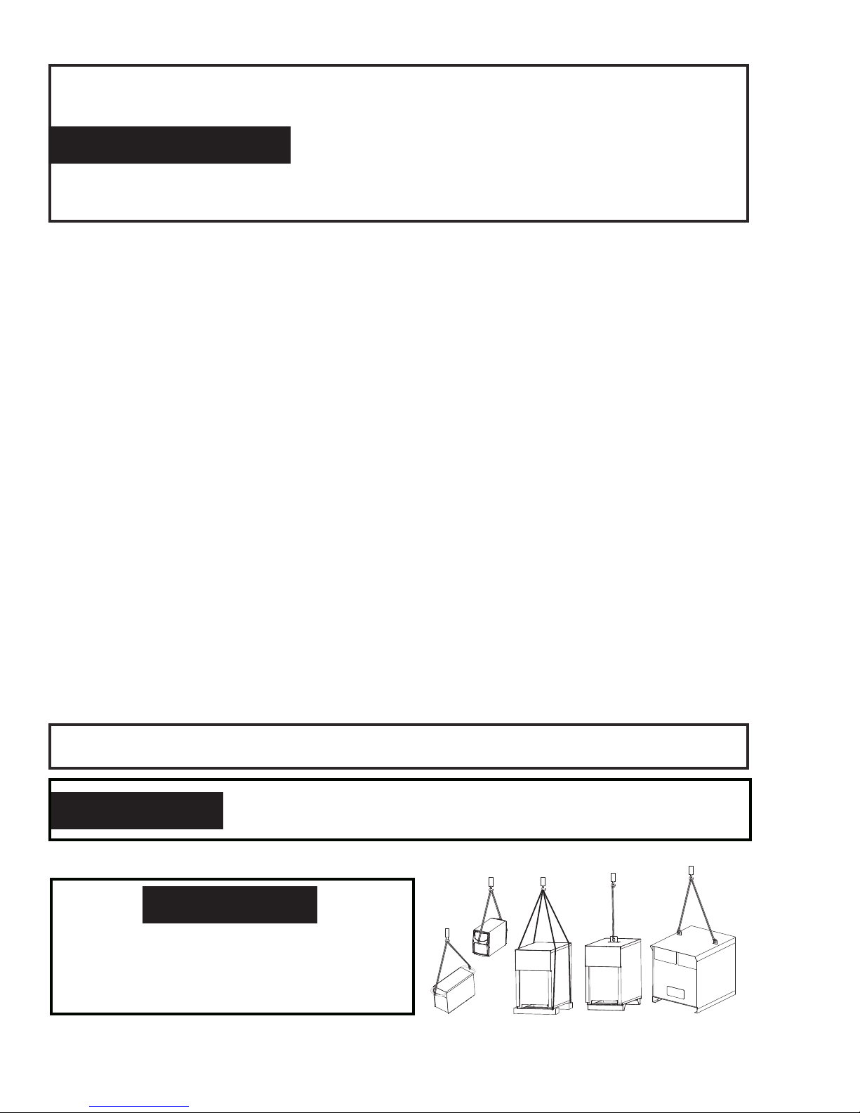
ATTENTION
Pour éviter toute blessure personnelle et/
ou endommagement à l’équipement, soulever à l’aide de la méthode et des points
d’attache indiqués ici.
SAFETY INSTRUCTIONS 1-4 Manual 0-5123
Page 11
SECTION 2:
!
INTRODUCTION
FIREPOWER FP 125,135,165
2.01 How To Use This Manual
This Owner’s Manual applies to just specification or part numbers
listed on page i.
To ensure safe operation, read the entire manual, including the
chapter on safety instructions and warnings.
Throughout this manual, the words WARNING, CAUTION, DANGER,
and NOTE may appear. Pay particular attention to the information
provided under these headings. These special annotations are
easily recognized as follows:
NOTE!
An operation, procedure, or background
information which requires additional
emphasis or is helpful in efficient operation
of the system.
CAUTION
!
!
Additional copies of this manual may be purchased by contacting
ESAB at the address and phone number in your area listed on
back cover of this manual. Include the Owner’s Manual number
and equipment identification numbers.
Electronic copies of this manual can also be downloaded at no
charge in Acrobat PDF format by going to the Firepower web site
listed below
http://www.firepoweronline.com
A procedure which, if not properly followed,
may cause damage to the equipment.
WARNING
A procedure which, if not properly followed,
may cause injury to the operator or others
in the operating area.
WARNING
Gives information regarding possible
electrical shock injury. Warnings will be
enclosed in a box such as this.
DANGER
Means immediate hazards which, if not
avoided, will result in immediate, serious
personal injury or loss of life.
2.02 Equipment Identification
The unit’s identification number (specification or part number),
model, and serial number usually appear on a data tag attached
to the rear panel. Equipment which does not have a data tag
such as torch and cable assemblies are identified only by the
specification or part number printed on loosely attached card or
the shipping container. Record these numbers on the bottom of
page i for future reference.
2.03 Receipt Of Equipment
When you receive the equipment, check it against the invoice to
make sure it is complete and inspect the equipment for possible damage due to shipping. If there is any damage, notify the
carrier immediately to file a claim. Furnish complete information
concerning damage claims or shipping errors to the location in
your area listed in the inside back cover of this manual.
Include all equipment identification numbers as described above
along with a full description of the parts in error.
Move the equipment to the installation site before un-crating
the unit. Use care to avoid damaging the equipment when using
bars, hammers, etc., to un-crate the unit.
2.04 General
The Firepower FP 125, 135, 165 Machines are single-phase input
welding machines and come equipped with the following:
1. Built-in Wire Feeder and Wire Spool Hub
2. Welding Gun and Cable
3. Work Cable and Clamp
4. Regulartor/Flow Meter (FP 125 optional)
5. Input Cord
6. 2 Spare Contact Tips
7. Operational Manual
8. 0.5 lb. Spool of Wire
9. Gas Hose
The welding system is designed for use with the following
processes:
1. GMAW - Gas metal arc welding (MIG). Requires the use of
a shielding gas and regulator.
2. FCAW – Flux-cored arc welding – Does not require the
use of a shielding gas.
Manual 0-5123 2-1 INTRODUCTION
Page 12

FIREPOWER FP 125,135,165
2.05 Specifications
Description FP 125 FP 135 FP 165
Package System Part Number 1444-0324 1444-0326 1444-0328
Power Source Weight 47.4 lb (21.5 kg) 52.9 lb (24.0kg) 58.1 lb (26.4 kg)
Power Source Dimensions HxWxD 12 x 9.75 x 17.5" ( 304.8 x 247.7 x 444.5mm)
Number of Phases 1 Ø
Frequency 60Hz
Flexible Supply Cable Size 7 ft (2.2 m) 14AWG 7 ft (2.2 m) 14AWG 7.5 ft (2.5 m) 14AWG
Supply Lead Plug Type 5-15P 5-15P 6-50P
Nominal Input Voltage
Rated kVA @ 100% Duty Cycle 5kVA 6kVA 7kVA
Rated Input Current 15A (60A@40%) 15A (60A@60%) 22.5A (120A@25%)
Maximum Input Current 38A (110A@10%) 50A (120A@13%) 35A (155A@15%)
Generator Requirements # 5kVA # 6kVA # 7kVA
Supply VA @ max. output # 4.6kVA # 5kVA # 6.8kVA
Open Circuit Voltage Range 16 – 30V 16 – 32V 15 – 30V
Output Current Range 40 – 125A 39 – 135A 36 – 165A
Duty Cycle Period 10 Minutes
Number of Output Voltage Values 4
Minimum Mains Circuit to suit factory fitted Plug &
Lead (Weld Current @ Duty Cycle)
120V AC 120V AC 230V AC
15A (60A@40%) 15A (60A@60%) 22.5A (120A@25%)
Maximum Mains Circuit to suit factory fitted Plug &
Lead (Weld Current @ Duty Cycle)
Steel
Stainless Steel
Flux Core
38A (110A@10%) 50A (120A@13%) 35A (155A@15%)
Wire Size Range
.023” - .030” - .035"
(0.6 - 0.8 - 0.9mm)
.030” - .035”
(0.8 - 0.9mm)
.023” - .030” - .035"
(0.6 - 0.8 - 0.9mm)
.030” - .035”
(0.8 - 0.9mm)
.023” - .030” - .035"
(0.6 - 0.8 - 0.9mm)
.030” - .035”
(0.8 - 0.9mm)
Table 2-1: System Specifications
∆ The recommended time delay fuse or circuit breaker size is 20 amp. An individual branch circuit capable of carrying 30 amperes and protected by fuses or circuit breaker is recommended for this application. Fuse size is based on not more than 200 percent
of the rated input amperage of the welding power source (Based on Article 630, National Electrical Code)
Firepower continuously strives to produce the best product possible and therefore reserves the right to change, improve or revise the
specifications or design of this or any product without prior notice. Such updates or changes do not entitle the buyer of equipment
previously sold or shipped to the corresponding changes, updates, improvements or replacement of such items.
The values specified in the table above are optimal values, your values may differ. Individual equipment may differ from the above specifications due to in part, but not exclusively, to any one or more of the following; variations or changes in manufactured components,
installation location and conditions and local power grid supply conditions.
INTRODUCTION 2-2 Manual 0-5123
Page 13
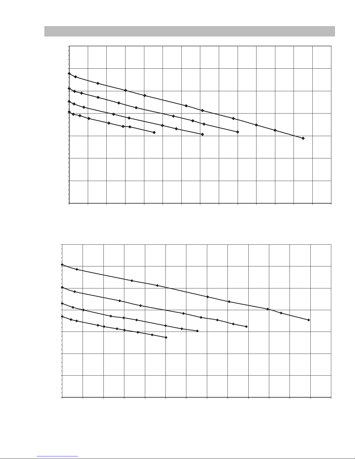
2.06 Volt - Amp Curves
FP 125 FIREPOWER Vin=115V 60Hz
5.0
10.0
15.0
20.0
25.0
30.0
35.0
0102030405060708090 100 110 120 130 140
OUTPUT CURRENT
OUTPUT VOLTAGE
Art # A-09076_AB
FP 135 FIREPOWER Vin=115V 60Hz
OUTPUT CURRENT
OUTPUT VOLTAGE
FIREPOWER FP 125,135,165
Figure 2-1: Volt/Amp curves of the Firepower 125
35
Art # A-09077_AB
30
25
20
15
10
5
0
0102030405060708090 100 110 120 130
Manual 0-5123 2-3 INTRODUCTION
Figure 2-1: Volt/Amp curves of the Firepower 135
Page 14

FIREPOWER FP 125,135,165
FP 165 FIREPOWER Vin=230V 60Hz
OUTPUT CURRENT
OUTPUT VOLTAGE
35
Art # A-09078_AB
30
25
20
15
10
5
0
0102030405060708090100 110 120 130 140 150 160 170 180 190
Figure 2-1: Volt/Amp curves of the Firepower 165
INTRODUCTION 2-4 Manual 0-5123
Page 15
FIREPOWER FP 125,135,165
Firepower 125 at Rated Duty Cycle
0
Minutes
910
Firepower 135 at Rated Duty Cycle
0
Minutes
91
Firepower 165 at Rated Duty Cycle
0
Minutes
910
2.07 Duty Cycle
Duty Cycle is the amount of arc-on time (actual welding time) during any 10 minute period that a machine can operate at it’s rated
output without damaging internal components. For example, the Firepower FP 135 is designed for 20% duty cycle at 117 amps. This
means that it has been designed and built to provide the rated amperage, 117 amps, for 2 minutes out of every 10 minute period. During the other 8 minutes of the 10 minute period, the Firepower FP 135 must idle and be allowed to cool. The thermal cutout will operate
if the duty cycle is exceeded.
The Firepower FP 125 is designed for 19% duty cycle at 90 Amps.
The Firepower FP 135 is designed for 20% duty cycle at 117 Amps.
The Firepower FP 165 is designed for 18% duty cycle at 140 Amps.
If the unit overheats and the thermostat opens, wait 15 minutes for unit to cool.
Art # A-09058_AB
1
1
1
23
45678
Figure 2-5: Duty Cycle of Firepower 125
23
45678
Figure 2-6: Duty Cycle of Firepower 135
23
45678
Figure 2-7: Duty Cycle of Firepower 165
Art # A-09059_AB
0
Art # A-09060_AB
Manual 0-5123 2-5 INTRODUCTION
Page 16
FIREPOWER FP 125,135,165
2.08 MIG Gun Maintenance
Remove dust and metallic particles from the gun conduit by forcing clean, dry compressed air into the conduit once a week. This will
minimize wire feeding problems.
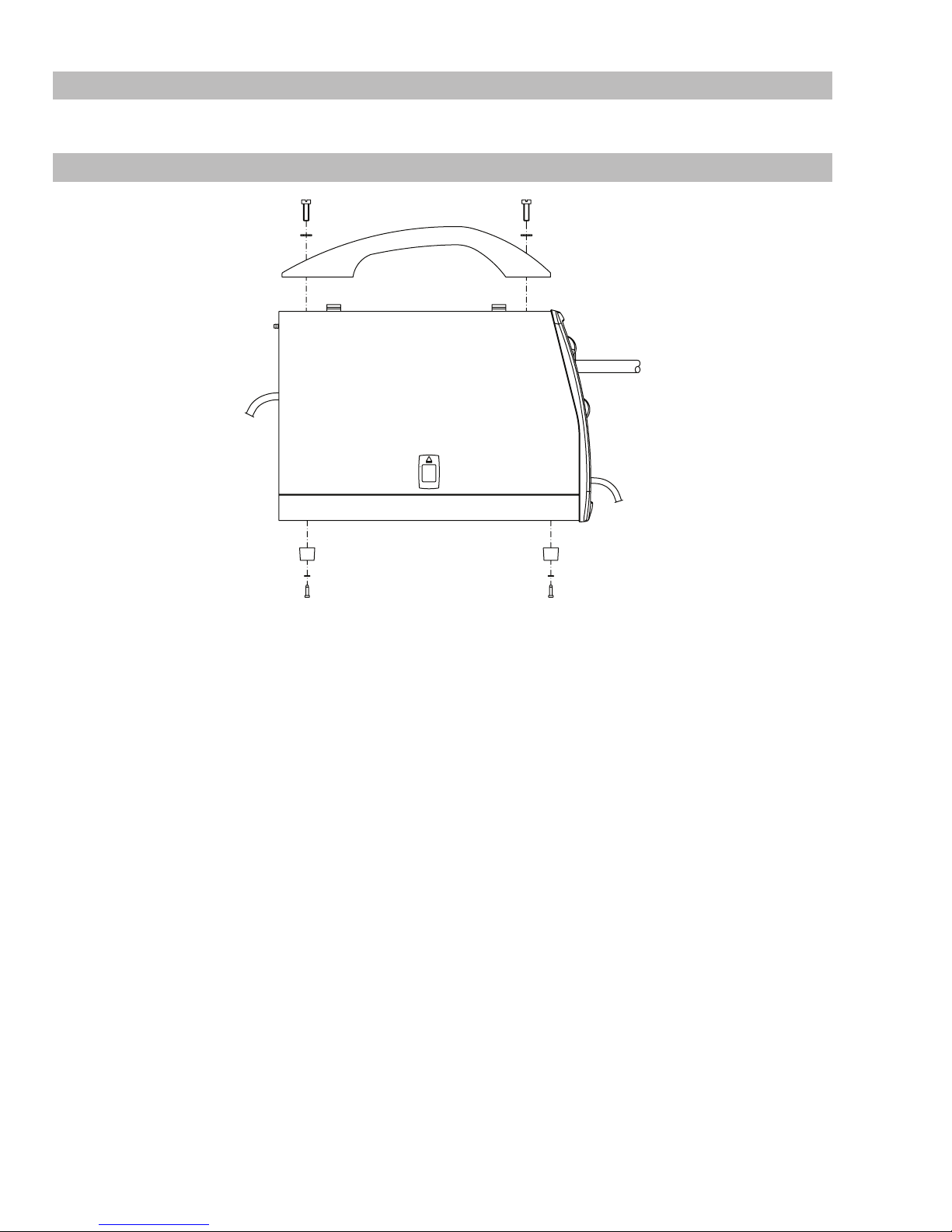
2.09 Handle / Feet Assembly
Art # A-09094
INTRODUCTION 2-6 Manual 0-5123
Page 17

SECTION 3:
INSTALLATION
FIREPOWER FP 125,135,165
3.01 Location
For best operating characteristics and longest unit life, take care
in selecting the installation site. Avoid locations exposed to high
humidity, dust, high ambient temperature, or corrosive fumes.
Moisture can condense on electrical components, causing corrosion or shorting of circuits. Dirt on components will retain this
moisture and also increases wear on moving parts.
Adequate air circulation is needed at all times in order to assure
proper operation. Provide a minimum of 12” (300mm) of free air
space at both the front and rear of the unit. Make sure that the
ventilation openings are not obstructed.
CAUTION
!
These MIG machines are not suitable for
use in rain.
3.02 Safety
Refer to additional installation instructions under the SAFETY
INSTRUCTIONS AND WARNINGS (Section 1) in this manual.
3.03 Grounding
The internal frame of this welding machine should be grounded
for personal safety. Where grounding is mandatory under state or
local codes, it is the responsibility of the user to comply with all
applicable rules and regulations. Where no state or local codes
exist, it is recommended that the National Electrical Code be
followed.
The National Electrical Code (Article 630B) provides standards for
amperage handling capability of supply conductors based on the
duty cycle of the welding power source. The Firepower FP 125
has a 19% duty cycle (1 minute 54 seconds of every 10 minutes
can be used for welding). The Firepower FP 135 has a 20% duty
cycle (2 minutes of every 10 minutes can be used for welding).
The Firepower FP 165 has an 18% duty cycle (1 minute 48 seconds of every 10 minutes can be used for welding). The power
cords supplied with these units comply with these standards.
Ensure that the building supply and receptacle comply with NEC
standards and any additional state and local codes.
NOTE!
The supply wiring for the welding power
source must be capable of handling a minimum of 20 amperes. The welding power
source must be the only load connected to
the supply circuit. Poor unit performance
or frequently opening line fuses or circuit
breakers can result from an inadequate or
improper supply.
CAUTION
!
Do not connect the Firepower FP 125 or
135 to an input power supply with a rated
voltage that is greater than 120 +10%
VAC. Do not remove the power cord ground
prong.
3.04 Electrical Input Requirements
Plug the input cord into a properly grounded and protected (by
fuse or circuit breaker) mains receptacle capable of handling a
minimum of 20 Amperes. Firepower FP 125 & FP 135 requires
a 120VAC supply voltage and the Firepower FP 165 requires a
230VAC supply voltage.
The Firepower FP 125 & FP 135's power cord is equipped with
a NEMA 5-15P plug and will only connect to a NEMA 5-15P
receptacle.
Except for some early models, the Firepower FP 165's power
cord is equipped with a NEMA 6-50P plug and will only connect
to a NEMA 6-50P receptacle.
CAUTION
!
Consult the nameplate for proper input
voltage and input amperage. The method
of installation, conductor size, and overcurrent protection shall conform to the requirements of the local electrical code. All
installation wiring and machine connection
shall be done by a competent electrician.
CAUTION
!
Do not connect the Firepower FP 165 to
an input power supply with a rated voltage
that is greater than 230 + 10% VAC. Do not
remove the power cord ground prong.
3.05 Requirements for Maximum Output
In order to obtain the maximum output capability of the Firepower FP 125 a branch circuit capable of 40 amperes at 115 to 125
Volts 60 Hz is required. In order to obtain the maximum output
capability of the Firepower FP 135 a branch circuit capable of 50
amperes at 115 to 125 Volts 60 Hz is required. In order to obtain
the maximum output capability of the Firepower FP 165 a branch
circuit capable of 30 amperes at 208 to 230 Volts 60 Hz is required. This generally applies when welding steel that is equal to
or greater than 12 gauge (0.105” 2.5mm) in thickness.
Manual 0-5123 3-1 INSTALLATION
Page 18

FIREPOWER FP 125,135,165
3.06 Installation of Shielding Gas (GMAW) Process
Refer to Figure 3-1.
NOTE!
Shielding Gas is not required if the unit is using self-shielded FCAW (flux cored arc welding) wires.
1. Cylinder Positioning: Chain the cylinder to a wall or other support to prevent the cylinder from falling over. If an optional portable mounting arrangement is used, follow the instructions that are provided with it.
2. Remove Cylinder Cap: Remove the large metal cap on top of the cylinder by rotating counter clockwise. Next remove the dust
seal.
3. Cracking: Position yourself so the valve is pointed away from you and quickly open and close the valve for a burst of gas. This
is called “Cracking” and is done to blow out any foreign matter that may be lodged in the fitting.
CAUTION
!
4. Fit Regulator/Flowmeter to Cylinders:
Screw the regulator into the appropriate cylinder. The nuts on the regulator and hose connections are right hand (RH) threaded and
need to be turned in a clockwise direction in order to tighten. Tighten with a wrench.
!
KEEP FACE WELL AWAY FROM THE CYLINDER VALVE DURING “CRACKING”. Never “crack” a fuel gas cylinder
valve near other welding works, sparks or open flames. Ensure that the surrounding area is well ventilated.
CAUTION
Match regulator to cylinder. NEVER CONNECT a regulator designed for a particular gas or gases to a cylinder containing any other gas.
5. Attach Supplied Gas Line: Attach supplied gas line between the regulator output and the desired input at the rear of the
power supply depending on Spool Gun or MIG Gun use.
INSTALLATION 3-2 Manual 0-5123
Page 19

1
FIREPOWER FP 125,135,165
Cap
2
Shielding
Gas
3
“Cracking”
Shielding
Gas
5
Gas Hose
Regulator and
Flow Meter
1 1/8”
Shielding
Gas
4
Shielding
Gas
Art # A-07965
Manual 0-5123 3-3 INSTALLATION
Figure 3-1 Gas Cylinder Installation for Reference Only!
Page 20

FIREPOWER FP 125,135,165
Adjusting Regulator
Adjust control knob of regulator to the required flow rate, indicated on gauge dial. (Refer to Figure 3-2 and data charts. Approx. 20 CFH)
The gas flow rate should be adequate to cover the weld zone to stop weld porosity. Excessive gas flow rates may cause turbulence and
weld porosity.
Argon or argon based gas flow rates:
- Workshop welding: 20-30 CFH
- Outdoors welding: 30-40 CFH
Helium based or CO2 gas flow rates:
- Workshop welding: 30-40 CFH
- Outdoors welding: 40-50 CFH
NOTE!
All valves downstream of the regulator must be opened to obtain a true flow rate reading on the outlet
gauge. (Welding power source must be triggered) Close the valves after the pressure has been set.
Art # A-07280
Figure 3-2: Adjusting flow rate. Illustration for Reference Only.
Refer to section 4.15 for suggested gas / filler metal combinations.
NOTE!
The regulator/flowmeters used with argonbased and carbon dioxide shielding gases are different. The
regulator/flow meter supplied is for argon based shielding gases. If carbon dioxide is to be used a suitable
carbon dioxide regulator/flow meter will need to be fitted.
Two types of gas are generally used with Gas Metal Arc Welding (GMAW) of thin gauge sheet steel. A mixture of 75% Argon and 25%
Carbon Dioxide (CO2) is recommended, Carbon Dioxide (CO2) can also be used.
INSTALLATION 3-4 Manual 0-5123
Page 21

3.07 Attaching the Gun and Cable
Assembly to the Power Source
The Firepower FP 125, FP 135, FP 165 are supplied with a 80A
MIG gun. The 80A MIG gun is designed with an ergonomic handle
and fewer parts to eliminate performance problems. The 80A MIG
gun uses standard readily available Firepower consumable parts.
1. Open the door to the machine.
2. Connect the gun cable to the power source by first routing
the switch lead through the access hole in the front panel
followed by the gun cable (see Figure 3-3).
NOTE!
Turn the cable end to align the gas hose
nipple on the connector plug with the
keyway located in the bottom of the front
panel access hole.
FIREPOWER FP 125,135,165
3. Loosen the screws and insert the gun cable end as far as
it will go. Tighten thumbscrew (see Figure 3-3).
4. Insert the gun switch plug into the gun switch socket (see
Figure 3-3).
5. If shielding gas is being used, push the gas hose on to the
gas hose nipple and secure it with the hose clamp.
6. To remove the gun, simply reverse these directions.
CAUTION
!
When disconnecting gun switch leads from the
machine, grab the connectors and pull. Do not
pull on the wires..
Gas Tube
Art # A-09079
Gun Switch Plug/Socket
Figure 3-3: Attaching Gun and Cable
Manual 0-5123 3-5 INSTALLATION
Page 22
FIREPOWER FP 125,135,165
Polarity
T
Leads
Gas Hose
Connected
Gas Tube
Leads
Polarity
T
Knobs
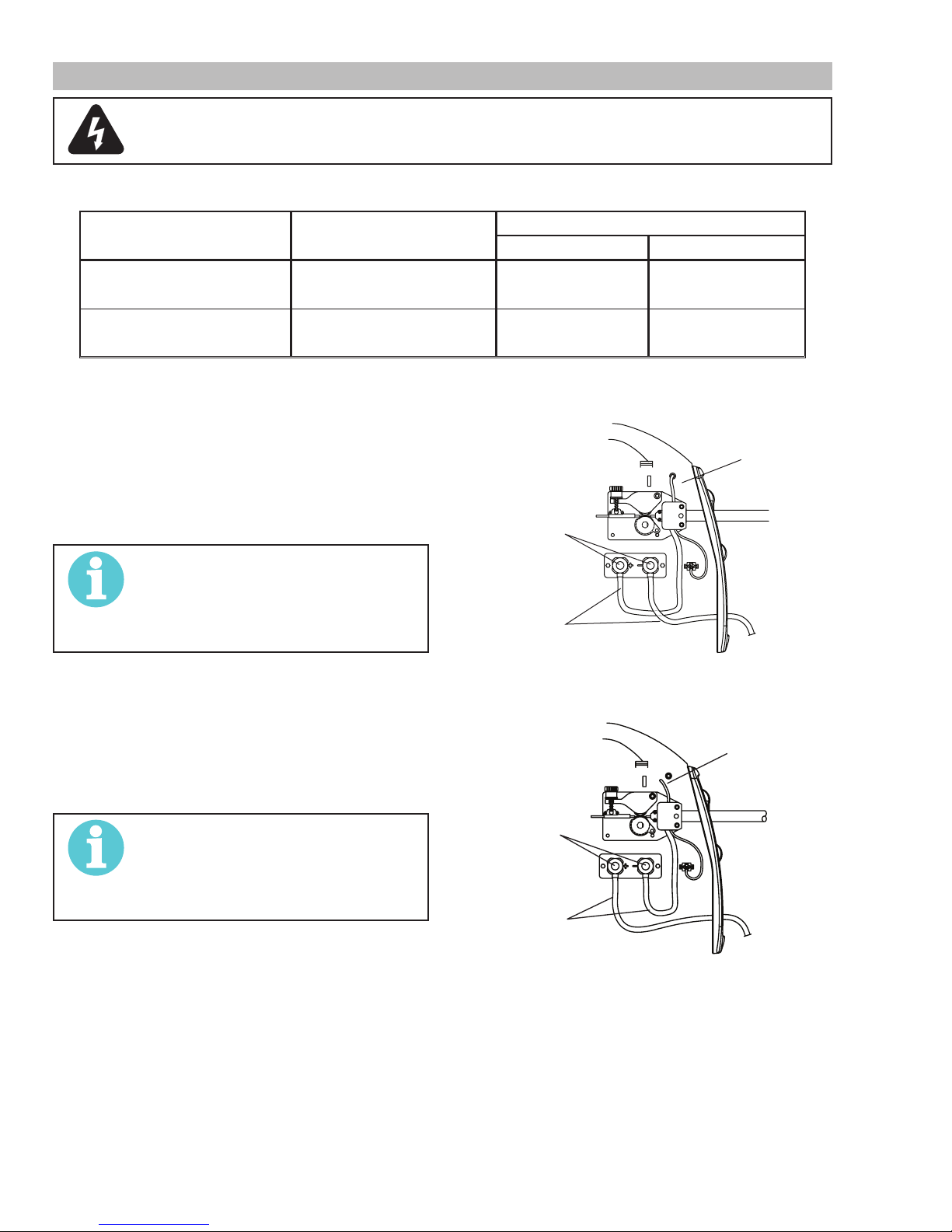
3.08 Polarity Changeover
WARNING
ELECTRIC SHOCK CAN KILL! Make certain the machine is unplugged from the power receptacle. Do not
plug machine in until told to do so in these instructions
As delivered from the factory, the output polarity is set to the polarity which matches the welding wire supplied with the unit. The output
terminals are located on the interior panel of the welding power source if you need to change polarity.
PROCESS POLARITY CABLE CONNECTIONS
CABLE TO GUN CABLE TO WORK
1. GMAW – Solid Wire 1. DCEP – Reverse Polarity 1. Connected to (+) Pos.
output terminal
1. Connected to (-) Neg.
output terminal
2. FCAW – Self-shielding Wire – no
2. DCEN – Straight Polarity 2. Connected to (-) Neg.
Shielding Gas
Table 3-1: Process Cable Connections
Connection for GMAW (reverse polarity DCEP)
1. Open the door to the machine.
2. Remove the polarity terminal knobs.
3. Set up the polarity (as per Table 3-1 above) by removing the leads from the terminals and reversing them if
necessary. Refer to Figure 3-4.
4. Replace the polarity terminal knobs.
NOTE!
Ensure that the polarity terminal knobs
are tightly secured and that there is no
connection between positive and negative
terminals.
Connection for FCAW (straight polarity DCEN)
1. Open the door to the machine.
2. Remove the polarity terminal knobs.
3. Set up the polarity (as per Table 3-1 above) by removing the leads from the terminals and reversing them if
necessary. Refer to Figure 3-5.
4. Replace the polarity terminal knobs.
NOTE!
Ensure that the polarity terminal knobs
are tightly secured and that there is no
connection between positive and negative
terminals.
2. Connected to (+) Pos.
output terminal
Polarity
Terminal
Knobs
erminal
output terminal
Normally
Art # A-09080
Figure 3-4: Connection for GMAW (reverse polarity DCEP)
Normally
Disconnected
erminal
Polarity
Terminal
Art # A-09081
INSTALLATION 3-6 Manual 0-5123
Figure 3-5: Connection for FCAW (straight polarity DCEN)
Page 23

FIREPOWER FP 125,135,165
3
Art # A-09082
3.09 Installing Wire Spool
As delivered from the factory, the unit is set for an 4” (102mm)
spool.
Installation of Wire Spool
Assemble parts in sequence (shown in Figure 3-6 from right to
left).
1. Spool 4” (102mm)
2. External Ring
3. Retaining Spring
4. Nut
NOTE!
Nut is tightened until a slight force is required to turn the spool.
1
2
4
3.10 Feedrolls
A feedroll consists of two different sized grooves, .023” (0.6mm)
and .030” / .035” (0.8mm / 0.9mm).
The branding inside at the end of the feedroll refers to the size
nearest to the mark
This also applies to optional feedrolls which are available for this
machine.
.030
0.8
Art # A-07963
Figure 3-7 : Feedroll Example
3.11 Install Wire into the Feedhead
WARNING
ELECTRIC SHOCK CAN KILL! Make certain
the machine is unplugged from the power
receptacle. Do not plug machine in until
told to do so in these instructions.
1. Loosen the nut of the spool holder (brake drum). Remove the spring and the external ring.
2. Remove the plastic protection from the spool. Place it
on the spool holder again. Mount the external ring , the
spring and the plastic lock nut again. These parts form
the braking system for the wire spool. Tighten nut to
appropriate tightness. Excessive pressure strains the
wire feeding motor. Too little pressure does not allow the
immediate stop of the wire spool at the end of the welding.
CAUTION
!
Use care in handling the spooled wire as it
will tend to “unravel” when loosened from
the spool. Grasp the end of the wire firmly
and do not let go of it. Make sure that the
end of the wire is free of any burrs and is
straight.
Figure 3-6: 4" Spool Installation
Manual 0-5123 3-7 INSTALLATION
Page 24
FIREPOWER FP 125,135,165
Pressure Arm
Pressure Arm
Pressure Adjust Device
Pressure Arm
Wire Guide
Gun Cable End
Pressure Adjust Device
Gun Cable End
Wire
Wire Spool Inlet Wire Guide Feedroll
Art # A-09083
Figure 3-8: Wire Feeder Components
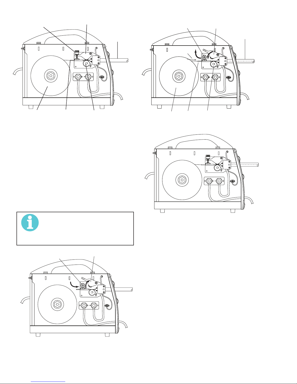
Route the Wire Through the Feedhead
1. Loosen Pressure Adjust Device (Fig. 3-9).
2. Open Pressure Adjust Device (Fig. 3-9).
3. Open Pressure Arm (Fig. 3-9).
4. Place the end of the wire into the Inlet Wire Guide,
feeding it over the Feedroll. Make certain that the proper groove
is being used (Fig. 3-10).
5. Pass the wire into the Gun Liner of the Gun Cable End
(Fig. 3-10).
6. Close the Pressure Arm (Fig. 3-10).
7. Close the Pressure Adjust Device. Tighten it to a “snug”
condition (Fig. 3-10).
8. Figure 3-11 shows the result with the wire installed.
NOTE!
If there is too much pressure on the drive
roll the wire gets locked and the motor
could get damaged, If it is too loose the
wire will not feed properly.
Spool
Feedroll
Figure 3-10: Inserting Wire
Figure 3-11: Wire Installed
Art # A-09085
Pressure Adjust Device
Art # A-09084
Figure 3-9: Opening Pressure Arm
INSTALLATION 3-8 Manual 0-5123
Page 25

3.12 Install Wire into the Welding Gun
2
HIGH
V
Switch
OFF Switch
Art # A-09062_AB
V
Switch
OFF Switch
2
HIGH
V
Switch
OFF Switch
Art # A-09062_AB
V
Switch
OFF Switch
Contact Tip
Nozzle
1. Plug the Welding Power Source into the 120VAC receptacle for the Firepower FP 125 and FP 135, and into the
230VAC receptacle for the Firepower FP 165.
WARNING
ELECTRIC SHOCK CAN KILL! With the gun
switch (located on the gun) activated,
welding power is applied to the output
terminals, feedroll, ground clamp, gun cable
connection and welding wire. Do not touch
these parts with the gun switch activated. .
2. Turn the welding machine ON with the front panel Voltage Control Switch set to "1".
Wire Feed
Speed
Art # A-09061_AB
v
oltage Control
COARSEFINE
LOW1
Power ON
FIREPOWER FP 125,135,165
Wire Feed
Speed
Power ON
oltage Control
Figure 3-15: FP 135, 165 Wire Speed Half-way
4. Straighten the gun cable. Remove the nozzle and contact tip from the MIG welding gun (see Section 2.08).
WARNING
If ground connection clamp is in place
on the workpiece the electrode wire is
electrically “hot” when the gun switch is
activated.
5. Activate the gun switch until the wire feeds out past the
gun nozzle.
Figure 3--12: FP 125 Power ON
Wire Feed
Speed
oltage Control
Figure 3--13: FP 135, 165 Power ON
3. Set the wire feed speed to half-way or "5".
Wire Feed
Speed
oltage Control
v
Art # A-09061_AB
COARSEFINE
LOW1
Power ON
Power ON
Wire
Gun Switch
Art # A-09087
Figure 3-15: Feed Wire Through Gun
6. Deactivate the gun switch and set the Power Control
Switch to "0 / OFF" and unplug the supply cord.
7. Replace the contact tip and nozzle. Cut the wire within
¼” (6mm) from the nozzle.
Figure 3-14: FP 125 Wire Speed Half-way
Manual 0-5123 3-9 INSTALLATION
Page 26

FIREPOWER FP 125,135,165
This Page Intentionally Blank
INSTALLATION 3-10 Manual 0-5123
Page 27

FIREPOWER FP 125,135,165
!
!
SECTION 4:
OPERATION
4.01 General Safety Precautions
Read and understand the safety instructions at the beginning of this manual prior to operating this machine.
WARNING
Be sure to put on proper protective clothing and eye safeguards (welding coat, apron, gloves, and welding
helmet, with proper lenses installed). See Safety Instructions and Warnings chapter included in this manual.
Neglect of these precautions may result in personal injury.
WARNING
Make all connections to the power source including electrode and work cables, as well as remote control
cables, with the power source turned off. These connections could be electrically live with the power switch
ON.
WARNING
ELECTRIC SHOCK CAN KILL! Do not operate the machine with the door open.
CAUTION
!
Do not pull the machine with the gun. Damage can occur to the gun, gun liner and machine. Avoid bending
the gun cable with a sharp radius. Damage can occur to the gun liner.
4.02 Firepower Controls
Refer to Figure 4-1 and 4-2.
1. Power ON / OFF switch turns the power on and off. It also lights when the power supply has gone into overtemp.
2. The Wire Speed Control knob controls the welding current via the electrode wire feed rate (i.e. the speed of the wire feed motor).
3. The Voltage Control Switch(s) sets the voltage level to the welding terminals. There are 4 positions available.
CAUTION
!
!
4. MIG Gun cable end and Gun Switch Leads are routed through this opening.
5. The Work Cable & Clamp connects to the item being welded (not shown).
6. The gas inlet nipple is used to connect the gas hose to the gas regulator for GMAW. Use the hose clamp to secure the hose to
7. The moveable tension knob applies pressure to the grooved roller via screw-adjustable spring pressure. The adjustable spring
8. The Gun Adaptor connects the MIG Gun to the feedhead assembly.
9. The Gun Switch Connector is provided for connection of the Gun Switch Leads.
10. Negative (-) Welding Terminal.
11. Positive (+) Welding Terminal.
The Voltage Control Switch MUST NOT BE SWITCHED during the welding process. Some internal electrical
components are at Mains voltage potential with this switch in the OFF position.
CAUTION
The Voltage Control Switch MUST NOT BE SWITCHED during the welding process. Some internal electrical
components are at Mains voltage potential with this switch in the OFF position.
the gas nipple.
screw should be adjusted to a minimum pressure that will provide satisfactory wire feed without slippage. If slipping occurs,
and inspection of the wire contact tip reveals no wear, distortion or burn-back jam, the conduit liner should be checked for
kinks and clogging by metal flakes and slag. If this is not the cause of slipping, the feedroll pressure can be increased by rotating the adjustable spring screw clockwise. The use of excessive pressure may cause rapid wear of the feed roller, motor shaft
and motor bearings.
Manual 0-5123 4-1 OPERATION
Page 28

FIREPOWER FP 125,135,165
4
CAUTION
!
13. The wire reel hub incorporates a friction brake which is adjusted during manufacture for optimum braking. If it is considered
!
Loose welding terminal connections can cause overheating and result in the cables being fused to the
welding terminals.
necessary, adjustment can be made by turning the large nut inside the open end of the wire reel hub. Clockwise rotation will
tighten the brake. Correct adjustment will result in the wire reel circumference continuing no further than ¾” (20mm) after
release of the Torch Trigger Switch. The wire should be slack without becoming dislodged from the reel.
CAUTION
Excessive tension on the brake will cause rapid wear of mechanical wire feed parts, overheating of electrical components and possibly an increased incidence of wire burnback into the contact tip.
2
6
3
8
9
Art # A-09065_AB
3
1
13
12 11
10
Figure 4-1: Firepower FP 125 Controls
2
6
4
7
Figure 4-2: Firepower FP 135 and 165 Controls
OPERATION 4-2 Manual 0-5123
8
1
3
Art # A-09066_AB
12
11 10
9
Page 29

FIREPOWER FP 125,135,165
!
4.03 Gas Metal Arc Welding (GMAW)
See Welding Guidelines included in this manual.
Make all necessary connections as instructed in the INSTALLATION chapter.
Place the WELD VOLTAGE RANGE SWITCH at the desired setting.
CAUTION
!
Plug the supply cord into a 120 VAC 40 Ampere receptacle for the FP 125, 120 VAC 50 Ampere receptacle for the 135 and into a 230
VAC 30 Ampere receptacle for the FP 165.
Open the gas cylinder valve to supply shielding gas to the gun. (optional gas regulator required on the FP 125)
Connect the WORK CLAMP to the workpiece (material to be welded).
Rotate the WIRE SPEED control to the desired setting.
Extend wire from the gun, and cut to proper stick-out for that type of wire (when welding always maintain this distance).
Position gun to where it is at approximately right angles to the workpiece with proper wire stick-out. Lower your welding helmet and
pull the gun trigger switch.
Do not turn the WELD VOLTAGE RANGE SWITCH clockwise past position 4, as damage to the switch may
occur.
WARNING
Be sure to put on proper protective clothing and eye safeguards (welding coat, apron, gloves, and welding
helmet with proper lenses installed). See Safety Instructions and Warnings chapter included in this manual.
Neglect of these precautions may result in personal injury.
Travel at a speed necessary to maintain a bead width from 1/8" to ¼" (3mm to 6mm) depending on the thickness of the material. For
material that may require larger weldments, either change to a larger diameter filler wire or use multi pass beads. On some applications, it may be necessary to adjust the voltage range to stabilize the arc.
Upon completion of the weld, release the gun trigger switch, raise the welding helmet, and visually examine the weld.
NOTE!
To help you overcome any problems that might arise, you will find useful information in section 4.06 Basic Welding
Techniques..
4.04 Flux Cored Arc Welding (FCAW)
Follow the same general procedure as with the GMAW process above. Shielding gas is not required for self shielded type wires. For
differences in the process see section 4.06 Basic Welding Techniques. Also included is information to solve any problem related to the
FCAW process.
4.05 Shutdown Procedures
Close the cylinder valve (GMAW process only). Press gun switch to vent gas line (GMAW process only). Place the POWER ON/OFF
SWITCH in the OFF position.
WARNING
!
After releasing the gun switch, the electrode wire will remain electrically “hot” for several seconds.
4.06 Basic Welding Technique
General
Two different welding processes are covered in this section, with the intention of providing the very basic concepts in using the semiautomatic mode of welding. In this mode, the welding gun is hand-held. The electrode (welding wire) is then fed into a weld puddle and
the arc is shielded by a gas or gas mixture.
Setting of the Power Supply
The settings of the Firepower requires some practice by the operator in that the welding Power Supply has two control settings that
need to balance. These are the Wire Speed control and the Voltage Control switches. The welding current is determined by the Wire
Speed control (i.e., the current will increase with increased wire speed, resulting in a shorter arc). Slower wire speed will reduce the
current and lengthen the arc. Increasing the welding voltage hardly alters the welding current level, but lengthens the arc. By decreasing the voltage, a shorter arc is obtained with little change in welding current.
Manual 0-5123 4-3 OPERATION
Page 30

FIREPOWER FP 125,135,165
Art: A-05104
!
When changing to a different electrode wire diameter, different control settings are required. A thinner electrode wire needs more wire
speed to achieve the same current level.
A satisfactory weld cannot be obtained if the wire speed and voltage switch settings are not adjusted to suit the electrode wire diameter and dimensions of the work piece.
If the wire speed is too high for the welding voltage, “stubbing” will occur as the wire dips into the molten pool and does not melt.
Welding in these conditions normally produces a poor weld due to lack of fusion. If however, the welding voltage is too high, large drops
will form on the end of the electrode wire, causing spatter. The correct setting of voltage and wire speed can be seen in the shape of
the weld deposit and heard by a smooth regular arc sound.
GAS METAL ARC WELDING (GMAW)
This process, also known as MIG welding, CO2 welding, Micro Wire Welding, short arc welding, dip transfer welding, wire welding etc.,
is an electric arc welding process which fuses together the parts to be welded by heating them with an arc between a solid, continuous, consumable electrode and the work. Shielding is obtained from an externally supplied gas or gas mixture. The process is normally
applied semi-automatically; however the process may be operated automatically and can be machine operated. The process can be
used to weld thin and fairly thick steels, and some non-ferrous metals in all positions.
Shielding Gas
Weld Metal
Solidified Weld
Metal
Nozzle
Electrode
Arc
Base Metal
Art: A-05103
Figure 4-3: GMAW Process
FLUX CORED ARC WELDING (FCAW)
This process also known as Open arc, Innershied, FAB Shield, etc., is an electric arc welding process which fuses together the parts
to be welded by heating them with an arc between a continuous flux filled electrode wire and the work. Shielding is obtained through
decomposition of the flux within the tubular wire. The process is normally applied semi-automatically; however the process may be
applied automatically or by machine. It is commonly used to weld large diameter electrodes in the flat and horizontal position and small
electrode diameters in all positions. The process is used to a lesser degree for welding stainless steel and for overlay work.
Gas (optional)
Molten Metal
Solid Weld
Metal
Slag
Molten
Slag
Nozzle (optional)
Flux Cored
Electrode
Arc
WARNING
Follow these instructions only after referring to the Safety Instructions and Warnings chapter of this manual,
and the instructions in the Installation chapter. .
Check List Before Starting
POLARITY – DCEP (Direct Current Electrode Positive) or DCEN (Direct Current Electrode Negative)
WIRE FEED SPEED – 1 to 10
VOLTAGE RANGE SWITCH SETTING – 1 to 4 for FP 135, 165 an two switches and1-2 and Low-High for FP 125.
GAS FLOW RATE – 15 to 25 CFH (If shielding gas is required)
ELECTRODE WIRE STICK-OUT – approx 3/8” (10mm)
OPERATION 4-4 Manual 0-5123
Figure 4-4: FCAW Process
Page 31

FIREPOWER FP 125,135,165
30 to 60º
T
Angle
Direction of
T
4.07 Welding Gun Positions
The welding gun should be held at an angle to the weld joint (see Secondary Adjustment Variables in Section 4.08). Hold the gun so that
the welding seam is viewed at all times. Always wear the welding helmet with proper filter lenses.
CAUTION
!
The electrode wire is not energized until the gun trigger switch is depressed. The wire may therefore be placed on the seam or joint
prior to lowering the helmet.
Do not pull the welding gun back when the arc is established. This will create excessive wire extension
(stickout) and make a very poor weld.
5º to 15º
Longitudinal
Angle
Direction of
90º
Transverse
Angle
Travel
Art: A-05105
Figure 4-5: Butt and Horizontal Welds
10º Longitudinal Angle
ransverse
Figure 4-6: Vertical Weld
5 to 15º
Longitudinal Angle
ravel
Figure 4-7: Horizontal Fillet Weld
10 to 20º Longitudinal
Angle
Direction of Travel
30 to 60º
Transverse Angle
Art: A-05107
Direction of Travel
30º
to 60º
Transverse
Angle
Art: A-05106
Manual 0-5123 4-5 OPERATION
30 to 60º
Transverse Angle
Figure 4-8: Overhead
5 to 15º
Longitudinal
Angle
Art: A-05108
Page 32

FIREPOWER FP 125,135,165
Actual Stickout
Transverse
4.08 MIG Welding (GMAW) Variables
Most of the welding done by all processes is on carbon steel. The following items describe the welding variables in short-arc welding of 24 gauge (0.024”, 0.6mm) to ¼” (6.4mm) mild sheet or plate. The applied techniques and end results in the GMAW process are
controlled by these variables.
Pre-selected Variables
Pre-selected variables depend upon the type of material being welded, the thickness of the material, the welding position, the deposition rate and the mechanical properties. These variables are:
1. Type of electrode wire
2. Size of electrode wire
3. Type of gas (not applicable to self-shielding wires FCAW)
4. Gas flow rate (not applicable to self-shielding wires FCAW)
Primary Adjustable Variables
These control the process after Pre-selected Variables have been found. They control the penetration, bead width, bead height, arc
stability, deposition rate and weld soundness. They are:
1. Arc Voltage
2. Welding Current (wire feed speed)
3. Travel Speed
Secondary Adjustable Variables
These variables cause changes in primary adjustable variables which in turn cause the desired change in the bead formation. They are:
1. Stickout—distance between the end of the contact tube (tip) and the end of the electrode wire. Keep this at about 3/8” (10mm)
stickout (as shown in Figure 4-8).
Gas Nozzle
Tip to Work
Distance
Average Arc Length
Contact Tip (Tube)
Electrode Wire
Art: A-05109
Figure 4-9: Electrode Stick-Out
2. Wire Feed Speed. Increase in wire feed speed increases weld current. Decrease in wire feed speed decreases weld current.
3. Nozzle Angle. (Figures 4-9 and 4-10) This refers to the position of the welding gun in relation to the joint. The transverse angle
is usually one half the included angle between plates forming the joint. The longitudinal angle is the angle between the center
line of the welding gun and a line perpendicular to the axis of the weld. The longitudinal angle is generally called the Nozzle
Angle and can be either trailing (pulling) or leading (pushing). Whether the operator is left-handed or right-handed has to be
considered to realize the effects of each angle in relation to the direction of travel.
Angle
Longitudinal
Angle
Axis of Weld
Figure 4-10: Transverse and Longitudinal Nozzle Axes
OPERATION 4-6 Manual 0-5123
Art: A-05110
Page 33

FIREPOWER FP 125,135,165
Direction of Gun Travel
Art # A-05111
Leading or "Pushing"
Angle (Forehand)
90º
Figure 4-11: Nozzle Angle, Right-Handed Operator
4.09 Establishing the Arc and Making Weld Beads
Before attempting to weld on a finished piece of work, it is recommended that practice welds be made on a sample metal of the same
material as that of the finished piece.
The easiest MIG welding procedure for the beginner to experiment with, is the flat position. This equipment is capable of flat, vertical
and overhead positions.
For practicing MIG welding, secure some pieces of 16 or 18 gauge (0.06” 1.5mm or 0.08” 2.0mm) mild steel plate 6” x 6” (150 x
150mm). Use 0.024” (0.6mm) wire and 75% Argon / 25% CO2 shielding gas.
Trailing or "Pulling"
Angle (Backhand)
4.10 Pre-Weld Procedure
1. Check the OPERATION chapter of this manual for details on this equipment.
2. Set the welding voltage range switch at position 1 or 2.
3. Set the wire feed speed control to about the 2.5 setting. Readjust as necessary.
4. Adjust the gas flow rate to about 20 cubic feet per hour (15 - 20 lpm).
5. Review standard safe practice procedures in ventilation, eye and face protection, fire, compressed gas and preventative maintenance. See Safety Instructions and Warnings chapter included in this manual.
4.11 Welding Procedure
1. Maintain the tip to work distance (stickout) at 5/16” to 3/8” (8 to 9mm) at all times.
2. For transverse and longitudinal nozzle angles, see section 4.07 Welding Gun Positions.
3. Hold the gun about 3/8” (9mm) from the work, lower the helmet by shaking your head and squeeze the trigger to start the wire
feeding, and establish the arc.
NOTE!
Get in the habit of shaking the helmet down, rather than using the hands. One hand must hold the gun, and
the other is often needed to hold pieces to be tacked or positioned.
4. Make a single down-hand (pulling) stringer weld bead.
5. Practice welding beads. Start at one edge and weld across the plate to the opposite edge.
NOTE!
When the equipment is properly adjusted, a rapidly cracking or hissing sound of the arc is a good indicator
of correct arc length.
6. Practice stopping in the middle of the plate, restarting into the existing weld crater and continuing the weld bead across the
plate.
NOTE!
When the gun trigger is released after welding, the electrode forms a ball on the end. To the new operator,
this may present a problem in obtaining the penetration needed at the start of the next weld. This can be
corrected by cutting the ball off with wire cutters.
Manual 0-5123 4-7 OPERATION
Page 34

FIREPOWER FP 125,135,165
4.12 Reference Tables
The following tables are provided as user aids when performing MIG or FLUX CORED welding.
Type of Gas Typical Mixtures Primary Uses
Carbon Dioxide (CO2) Mild and low alloy steels
Argon (Ar) - Carbon Dioxide (CO2) 75% Ar – 25% CO2 Mild and low alloy steelsStainless Steel
Argon (Ar) Aluminum
Table 4-1: Type of Gas
Result Desired Welding Variable
Arc
Voltage
Deeper Penetration 1Increase 3Trailing Max 25° 2Decrease
Shallower
Penetration 1Decrease 3Leading 2Increase 5Larger
Larger Bead 1Increase 2Decrease 3Increase (*)
Smaller Bead 2Decrease 2Increase 3Decrease (*)
Higher Narrower
Bead 1Decrease 2Trailing 3Increase
Flatter Wider Bead 1Increase 290° or Leading 3Decrease
Faster Deposition
Rate 1Increase 2Increase (*) 3Smaller
Slower Deposition
Rate 1Decrease 2Decrease (*) 3Larger
Key: (1) First Choice, (2) Second Choice, (3) Third Choice, (4) Fourth Choice, (5) Fifth Choice
Welding Current
(wire speed)
Travel
Speed Nozzle Angle Stick out Wire size Gas Type
5Smaller
(*) 4CO2
Table 4-2: Welding Variables
NOTE!
Same adjustment is required for wire feed speed.
4Ar CO2
mix
* When these variables are changed, the wire feed speed must be adjusted so that the welding current remains constant. See DEPOSITION RATE in the WELDING VARIABLES section. This change is especially helpful on materials of 20 gauge (.04” 1mm approximately)
and smaller in thickness.
OPERATION 4-8 Manual 0-5123
Page 35

FIREPOWER FP 125,135,165
Art # A-09030_AB
Steel
Flux Core
E71T-GS
None
Required
.030" (0.8mm)
.035" (0.9mm)
Steel
ER70S-6
Solid
(or hard)
100% CO
2
25cfh
.023" (0.6mm)
.030" (0.8mm)
.035" (0.9mm)
.023" (0.6mm)
.030" (0.8mm)
.035" (0.9mm)
75% Ar
25cfh
CO
2
25%
L1
L1
L1
5
L1
3.5
L1
3.5
5
3.5
L1
L1
L1
566 7.5
5
4
8
5
6
4.5
3
7
4
4
4
7
4
3
5
3.5
L2 L2 H1
H1
H1
H1
H1
H1
8
6
5
8.5
7.5
6.5
H2
H2
H2
H2
H2
H2
6
7.5
6.5
H2
H2
H2
H1
L2
L2
L1
L1
L2
3
L2
L2
L1
L1
564
L1
3
L1
7.5
643
H1
6.5
H2L1L1
L2
L2
H2
H2
8.5
7.5
H2
24 ga. (0.6mm)
22 ga. (0.7mm)
20 ga. (0.9mm)
18 ga. (1.2mm)
16 ga. (3mm)
1/8" (3.2mm) 3/16" (4.8mm)
Wire
Speed
Voltage
Step
THICKNESS
FINE
1
2
COARSE
LOW
HIGH
Material Type Wire Type Shielding Gas
and Flow Rate
Wire Size
(Diameter)
4.13 Firepower FP 125 Welding Setting Selection Guide
Manual 0-5123 4-9 OPERATION
Figure 4-12: FP 125 Selection Guide
Page 36

FIREPOWER FP 125,135,165
4.14 Firepower FP 135 Welding Setting Selection Guide
Material Type Wire Type Shielding Gas
and Flow Rate
100% CO
25cfh
Solid
Steel
(or hard)
ER70S-6
75% Ar
25%
CO
Wire Size
(Diameter)
.023" (0.6mm)
2
.030" (0.8mm)
.035" (0.9mm)
.023" (0.6mm)
2
.030" (0.8mm)
25cfh
.035" (0.9mm)
Steel
Stainless
Steel
3
2
1
4
Voltage
Step
Wire
Speed
Flux Core
E71T-GS
Stainless
Steel
ER 308L
THICKNESS
None
Required
98% Ar
2% CO
35cfh
.030" (0.8mm)
.035" (0.9mm)
.023" (0.6mm)
2
.030" (0.8mm)
.035" (0.9mm)
Art # A-09031_AB
24 ga. (0.6mm)
2
3.5
2
2.5
1
3
1
2
1
2
1
3
22 ga. (0.7mm)
2
2
20 ga. (0.9mm)
3.54.5 5.56
2.5
223
2
1
1
3
1
2
1
1
1
1
2
1
2.5
2.5
3
3
2.5
18 ga. (1.2mm)
2
3
2
2.5
2
5
2
3.5
2
3
2
462.5
16 ga. (3mm)
2
3
2
2
2
3
3
1
3355.5
1
2
122
3
2.5
2
3.5
1
2.5
1
1
2
2
Figure 4-13: FP 135 Selection Guide
1/8" (3.2mm) 3/16" (4.8mm) 1/4" (6.4mm) 5/16" (7.9mm)
4
7.5
4.5
5
7.5
5.5
5
7 8.5
7
7.5
5.5
5.5
8
4
6
4
4.5
4
8
4
7
4
7
4
4
8
4
8
4
7
4
6.5
4
7
4
7
4
8.5
421
8
4
7
4
6.5
3
3.5
5.5
4
3.5
53.51.5
4
4
4
3
4
3
3
3
4
4
3
3
3
4
6.5
OPERATION 4-10 Manual 0-5123
Page 37

FIREPOWER FP 125,135,165
57
4.15 Firepower FP 165 Welding Setting Selection Guide
3
2
1
24 ga. (0.6mm)
1
3
1
3
1
1
1
4
1
3
1
1.5
Voltage
4
Step
22 ga. (0.7mm)
1
1
1
1
1
1
1.5
Material Type Wire Type Shielding Gas
Solid
Steel
(or hard)
ER70S-6
and Flow Rate
100% CO
2
25cfh
75% Ar
CO
2
25%
.023" (0.6mm)
.030" (0.8mm)
.035" (0.9mm)
.023" (0.6mm)
.030" (0.8mm)
25cfh
.035" (0.9mm)
Steel
Stainless
Steel
Flux Core
E71T-GS
Stainless
Steel
ER 308L
Wire
Speed
20 ga. (0.9mm)
333.55
122
1
1
3
1
1
1
1
1
4445.5
3
112
1
1
18 ga. (1.2mm)
1
2
1
3
2
1.5
1.51.5 3.5
3
1.5
2
1
1.5
2
4
1
2
2
2.5
1
1
3
1
2
None
Required
98% Ar
2% CO
35cfh
THICKNESS
16 ga. (3mm)
2
3
2
2
2
5
2
3.5
2
3
2
2
32.52.5
2
4
2
3
.030" (0.8mm)
.035" (0.9mm)
.023" (0.6mm)
2
.030" (0.8mm)
.035" (0.9mm)
1/8" (3.2mm) 3/16" (4.8mm) 1/4" (6.4mm) 5/16" (7.9mm)
3
3
3
3
3
3
3
3
3
3
3
Wire Size
(Diameter)
4
6
4
5
4
4
4
7
4
5.5
4
4.5
3
5 6
3
4
4
7
4
5.5
4
4
7
6.5
6
7.5
7
6.5
5
7.5
7
6
Art # A-09032_AB
4
6
4
8
4
6.5
4
422
4
4
4
7.
7
7.5
7
6
4
.5
4
7.5
4
6
Manual 0-5123 4-11 OPERATION
Figure 4-14: FP 165 Selection Guide
Page 38

FIREPOWER FP 125,135,165
4.16 Gas Selection for Gas Metal Arc Welding
Metal Type
Carbon
Steel
Low Alloy
and
High Alloy
Steel
Base Plate
Thickness Filler Metal
Greater than
22 gauge
(.030”)
Greater than
22 gauge
(.030”)
Greater than
22 gauge
(.030”)
Greater than
10 gauge
(1/8”)
Greater than
22 gauge
(.030”)
Greater than
22 gauge
(.030”)
ER70S-X Short Circuit 100% CO2All Position
ER70S-X Short Circuit 75% Argon
ER70S-X Short Circuit 92% Argon
ER70S-X Spray
See Note 1 Short Circuit
See Note 1 Short Circuit 92% Argon
Transfer
Mode
Transfer
Globular
Suggested
Shielding Gas
25% CO2
8% CO2
92% Argon
8% CO2
75% Argon
25% CO2
8% CO2
Welding
Positions Comments
High welding speeds. Good penetration and pool
Welding
All Position
Welding
All Position
Welding
Flat & HV
Fillet
All Position
Welding
All Position
Welding
Suitable for high-current and high-speed welding.
Higher deposition rates without melt-through.
Minimum distortion and spatter. Good pool control
for out-of-position welding.
Good arc stability, weld soundness, and increasing
High welding speeds. Good penetration and pool
control. Applicable for out-of-position welds.
Suitable for high-current and high-speed welding.
Good coalescence and bead contour. Good
control.
width of fusion.
mechanical properties.
Greater than
3/32”
Greater than
14 gauge
(.075”)
Stainless
Steel
Aluminum Greater than
Greater than
22 gauge
(.030”)
Greater than
3/32”
18 gauge
(.045”)
See Note 1 Spray
transfer
See Note 1 Short Circuit 98% Argon
ER308-X
ER309-X
ER316-X
ER308-X
ER309-X
ER316-X
ER4043
ER5356
Short Circuit 90% Helium
Spray
Transfer
Spray
Transfer
92% Argon
8% CO2
2% CO2
7.5% Argon
2.5% CO2 or
81% Argon
18% Helium
1 % CO2
90% Helium
7.5% Argon
2.5% CO2 or
81% Argon
18% Helium
1 % CO2
Argon All Position
Flat & HV
Fillet
All Position
Welding
All Position
Welding
Flat & HV
Fillet
Welding
Reduces undercutting. Higher deposition rates
and improved bead wetting. Deep penetration and
good mechanical properties.
Good control of melt-through and distortion. Used
also for spray arc welding. Pool fluidity sometimes
sluggish depending on the base alloy.
Low CO2 percentages in Helium mix minimizes
carbon pickup, which can cause intergranular
corrosion with some alloys. Helium improves
wetting action and contour. CO2 percentages
above 5% should be used with caution on some
alloys.
Good arc stability. Produces a fluid but controllable
weld pool, good coalescence, and bead contour.
Minimizes undercutting on heavier thickness.
Excellent cleaning action. Provides more stable arc
than helium-rich mixtures.
Note 1: Contact your Filler Metal Supplier for recommended filler metal for the base metal to be welded.
OPERATION 4-12 Manual 0-5123
Table 4-3: Gas Selection GMAW
Page 39

ESAB FIREPOWER FP-125,135,165
SECTION 5:
SERVICE
5.01 Cleaning of the Unit
Periodically remove the right side panel (after disconnecting the
supply cord from the receptacle) and blow out the interior with
clean, dry, compressed air of not more than 25 PSI air pressure.
Do not strike any components with the air hose nozzle.
5.02 Cleaning of the Feed Rolls
Clean the wire groove on the feed roll at frequent intervals. This
cleaning operation can be done by using a small wire brush. To
clean the wire groove, loosen the pressure device and lift the
feedroll pressure arm. Remove all wire from the feedhead. Wipe
off the bearing roll (the “top” roll in the feedhead).
5.03 Basic Troubleshooting
The basic level of troubleshooting is that which can be performed
without special equipment or knowledge, and without removing
the covers from the Power Source.
If major components are faulty, then the Power Source should be
returned to an Accredited Firepower Service Agent for repair.
5.04 Solving Problems Beyond the
Welding Terminals
NOTE!
The general approach to fix Gas Metal Arc
Welding (GMAW) problems is to start at the
wire spool then work through to the MIG
torch. There are two main areas where
problems occur with GMAW:
1. Porosity
When there is a gas problem the result is usually porosity within
the weld metal. Porosity always stems from some contaminant
within the molten weld pool which is in the process of escaping
during solidification of the molten metal.
Contaminants range from no gas around the welding arc to dirt
on the work piece surface. Porosity can be reduced by checking
the following points:
1. Gas cylinder contents and flow meter.
a. Ensure that the gas cylinder is not empty and the
flow meter is correctly adjusted to 20CFM (15 liters
per minute).
2. Gas leaks
a. Check for gas leaks between the regulator/cylinder
connection and in the gas hose to the Power Source.
3. Internal gas hose in the Power Source.
a. Ensure the hose from the solenoid valve to the MIG
torch adaptor has not fractured and that it is connected to the MIG torch adaptor.
4. Welding in a windy environment.
a. Shield the weld area from the wind or increase the
gas flow.
5. Welding dirty, oily, painted, oxidized or greasy plate.
a. Clean contaminates off the plate.
6. Distance between the MIG torch nozzle and the work
piece.
a. Keep the distance between the MIG torch nozzle and
the work piece to a minimum.
7. Maintain the MIG torch in good working order.
a. Ensure that the gas holes are not blocked and gas is
exiting out of the torch nozzle. Refer to WARNING
below.
b. Do not restrict gas flow by allowing spatter to build
up inside the MIG torch nozzle.
WARNING
Disengage the drive roll when testing for
gas flow by ear.
2. Inconsistent wire feed
Wire feeding problems can be reduced by checking the following
points:
1. Wire spool brake is too tight.
a. Feed roller driven by motor in the cabinet will slip.
2. Wire spool brake is too loose.
a. Wire spool can unwind and tangle.
3. Worn or incorrect feed roller size.
a. Use ‘U’ groove drive feed roller matched to the
aluminum wire size you are welding. Use ‘V’ groove
drive feed roller matched to the steel wire size you
are welding. Use ‘knurled V’ groove drive feed roller
matched to the flux cored wire size you are welding.
4. Misalignment of inlet/outlet guides.
a. Wire will rub against the misaligned guides and
reduces wire feedability.
5. Liner blocked with slag.
a. Slag is produced by the wire passing through the
feed roller, if excessive pressure is applied to the
pressure roller adjuster. Slag can also be produced
by the wire passing through an incorrect feed roller
groove shape or size. Slag is fed into the liner where
it accumulates, thus reducing wire feedability.
Manual 0-5123 5-1 SERVICE
Page 40

ESAB FIREPOWER FP-125,135,165
6. Incorrect or worn contact tip.
a. The contact tip transfers the weld current to the electrode wire. If the hole in the contact tip is too large, then arcing
may occur inside the contact tip resulting in the electrode wire jamming in there. When using soft electrode wire such
as aluminum, the wire may become jammed in the contact tip due to expansion of the wire when heated. A contact
tip designed for soft electrode wires should be used.
7. Poor work lead contact to work piece.
a. If the work lead has a poor electrical contact to the work piece, then the connection point will heat up and result in a
reduction of power at the arc.
8. Bent liner.
a. This will cause friction between the wire and the liner thus reducing wire feedability
5.05 Welding Problems
FAULT CAUSE REMEDY
Undercut.
1
A Welding arc voltage too
high.
B Incorrect torch angle B Adjust angle
A Reduce voltage by reducing the voltage selection
switch position or increase the wire feed speed.
C Excessive heat input C Increase the torch travel speed and/or reduce
welding current by reducing the voltage selection
switch position or reducing the wire feed speed.
Lack of penetration.
2
Lack of fusion. Voltage too low Increase voltage by increasing voltage selection
3
Excessive spatter.
4
Irregular weld shape. A Incorrect voltage and
5
A Welding current too low A Increase welding current by increasing wire feed
speed and increasing voltage selection switch position.
B Joint preparation too nar-
row or gap too tight
C Shielding gas incorrect C Change to a gas which gives higher penetration
A Voltage too high A Lower voltage by reducing the voltage selection
B Voltage too low B Raise voltage by increasing the voltage selection
current settings. Convex =
voltage too low. Concave
= voltage too high.
B Wire is wandering B Replace contact tip
C Incorrect shielding gas C Check shielding gas
B Increase joint angle or gap
switch position.
switch or increase wirespeed control.
switch or reduce wirespeed control.
A Adjust voltage and current by adjusting the voltage
selection switch and the wirespeed control.
D Insufficient or excessive
heat input
SERVICE 5-2 Manual 0-5123
D Adjust the wirespeed control or the voltage selec-
tion switch
Table 5-1a: Welding Problems
Page 41

ESAB FIREPOWER FP-125,135,165
FAULT
6 Weld cracking A Weld beads too small A Decrease travel speed
7 Cold weld puddle
8
Arc does not have a crisp
sound that short arc
exhibits when the wirefeed
speed and voltage are
adjusted correctly.
CAUSE REMEDY
B Weld penetration narrow
and deep
C Excessive weld stresses C Increase weld metal strength or revise design
D Excessive voltage D Decrease voltage by reducing the voltage selection
E Cooling rate too fast E Slow the cooling rate by preheating part to be
A Faulty rectifier unit A Have an Accredited ESAB Service Agent to test then
B Loose welding cable con-
nection.
C Low Primary Voltage C Contact supply authority
The MIG torch has been
connected to the wrong
voltage polarity on the
front panel.
B Reduce current and voltage and increase MIG torch
travel speed or select a lower penetration shielding
gas.
switch.
welded or cool slowly.
replace the faulty component.
B Check all welding cable connections.
Connect the MIG torch to the positive (+) welding
terminal for solid wires and gas shielded flux cored
wires. Refer to the electrode wire manufacturer for
the correct polarity.
9
Thermal overtemperature
light illuminatesduring
welding, but fan motor
continues to run.
10
Thermal overtemperature
light illuminates in less
than 30 seconds during
welding
The machine duty cycle
has been exceeded.
Fan has stopped running
or fuse on PCB has blown.
Allow the fan to run, to allow the machine to cool
down.
Have an accredited ESAB Service Agent replace the
fan motor or fuse.
Manual 0-5123 5-3 SERVICE
Page 42

ESAB FIREPOWER FP-125,135,165
This Page Intentionally Blank
SERVICE 5-4 Manual 0-5123
Page 43

FIREPOWER FP 125,135,165
APPENDIX 1: OPTIONS AND ACCESSORIES
• Contact your Firepower distributor to order options and accessories. For assistance in locating a Firepower distributor, contact
the ESAB office listed in the inside rear cover that is nearest to you.
• Note the model and specification number shown on the equipment nameplate.
For Firepower/ESAB Inquiries and Orders:
Call 1-800-318-6819 Consumable Parts Management Group
Replacement Torch Catalog number 1444-0741
FEED ROLL INSTALLATION & CONSUMABLE GUIDE
Wire Feed Rolls &
.030"
0.8mm
Part No.
1444-0427
1444-0050 Nozzle
1444-0025 Contact Tip, .023" (0.6mm)
1444-0026 Contact Tip, .030" (0.8mm)
1444-0027 Contact Tip, .035" (0.9mm)
1444-0489 Gas Diffuser
1444-0741 MIG Gun, Complete Assembly
Description
Wire Feed Roll, Knurle, .023" - .030" /.035"
(0.6-0.8mm/0.9mm), Hard/Cored
MIG Gun Consumables
The branding size at the
end of the feedroll refers
to the size nearest to the mark.
Part No.
1444-0210
1444-0211
1444-0215
1444-0216
1444-0220
1444-0221
1444-0230
1444-0231
1444-0235
1444-0236
Weld Wires
Description
ER70S-6 Mild Steel Wire,
.023" (0.6mm), 2 lbs. (0.9kg) Spool
ER70S-6 Mild Steel Wire,
.023" (0.6mm), 11 lbs. (5kg) Spool
ER70S-6 Mild Steel Wire,
.030" (0.8mm), 2 lbs. (0.9kg) Spool
ER70S-6 Mild Steel Wire,
.030" (0.8mm), 11 lbs. (5kg) Spool
ER70S-6 Mild Steel Wire,
.035" (0.9mm), 2 lbs. (0.9kg) Spool
ER70S-6 Mild Steel Wire,
.035" (0.9mm), 11 lbs (5kg) Spool
E71T-GS Flux Cored Wire,
.030" (0.8mm), 2 lbs (0.9kg) Spool
E71T-GS Flux Cored Wire,
.030" (0.8mm), 10 lbs (4.5kg) Spool
E71T-GS Flux Cored Wire,
.035" (0.9mm), 2 lbs (0.9kg) Spool
E71T-GS Flux Cored Wire,
.035" (0.9mm), 10 lbs (4.5kg) Spool
Art # A-09026
Figure A-1: FP 125 Feed Roll and Consumables Chart
Manual 0-5123 A-1 APPENDIX
Page 44

FIREPOWER FP 125,135,165
APPENDIX 2: REPLACEMENT PARTS
Item DESCRIPTION
1 TORCH GROMMET 1444-0477 1444-0477 1444-0477
2 FRONT PANEL FP 125 SILK-SCREEN PRINTED HELV05000348 HELV05000349 HELV05000350
3 PLASTIC HINGE FOR SIDE PANEL 1444-0435 1444-0435 1444-0435
4 SWITCH KNOB, FP 135/165 - 1444-0808
5 POTENTIOMETER KNOB, FP 125/135/165 1444-0543 1444-0543 1444-0543
6 YELLOW PILOT-LIGHT SWITCH 1444-0440 1444-0440 1444-0440
7 RIGHT COVER PANEL FP 125-135-165 HELV05000354 HELV05000354 HELV05000354
8 FRONT FRAME, FP 125/135/165 1444-0833 1444-0833 1444-0833
9 CAP D.36 FOR MIG 100 LOUVER 1444-0831 1444-0831 1444-0831
10 INPUT POWER CABLE (Not Shown) 1444-0433 1444-0433 1444-0463
11 EARTH CLAMP, FP 125/135/165 (Not Shown) 1445-0966 1445-0966 1445-0966
12 EARTH CABLE, FP 125/135/165 (Not Shown) 1444-0843 1444-0843 1444-0843
13 LOUVER MIG 100 1444-0830 1444-0830 1444-0830
14 CABLE CLAMP FOR CABLE DIAM.6+ SCREW (Not Shown) 1444-0806 1444-0806 1444-0806
15 MIG GUN, FP 125/135/165 (Not Shown) 1444-0741 1444-0741 1444-0741
16 FEMALE CONNECTOR, 9/16"X18 - 1444-0839 1444-0839
17 GAS REGULATOR, FP 135/165 - 1444-0838 1444-0838
18 GAS HOSE 1,5M + CONN. 9/16" + CLAMPS 1444-0809 1444-0809 1444-0809
19 P.C. BOARD 1444-0483 1444-0483 1444-0465
20 MOTOR & GEARBOX, FP 135 - 1444-0803 W7004002
21 RECTIFIER 1444-0836 1444-0836 1444-0837
22 THERMOSTAT, RECTIFIER 1444-0456 1444-0456 1444-0443
23 FAN KIT 1444-0486 1444-0486 W7004008
24 CABLE CLAMP 1444-0807 1444-0807 1444-0428
25 PLASTIC FOOT 1444-0495 1444-0495 1444-0495
26 TRANSFORMER 1444-0844 1444-0462 1444-0469
27 CHOKE 1444-0846 1444-0847 1444-0728
28 SWITCH 17A - 1444-0852 1444-0835
29 HOSE CONNECTOR D.4-HOSEHOLDER D.6 + NUTS 1444-0840 1444-0840 1444-0840
30 SPOOL HOLDER 1444-0800 1444-0800 1444-0800
31 MILD STEEL WIRE REEL 1444-0500 1444-0500 1444-0500
32 HANDLE, FP 125/135/165 1444-0828 1444-0828 1444-0828
33 WIRE FEEDER 1444-0848 1444-0850 1444-0491
34 WIRE FEED ROLL - 1444-0427 1444-0427
34b WIRE FEEDING D.28 + PINION 1444-0804 - -
35 KIT GAS/NO GAS CHANGE BOARD 1444-0802 1444-0802 1444-0802
36 DIVIDING PANEL FP + LABELS 1444-0825 1444-0826 1444-0826
37 DOOR LATCH 1444-0426 1444-0426 1444-0426
38 LEFT SIDE PANEL FP SILK+LAB+HINGE+LOCK HELV05000355 HELV05000356 HELV05000357
39 LOWER PANEL, FP 125/135/165 1444-0490 1444-0490 1444-0490
40 SWITCH 16A, FP 125 1444-0834 - -
41 THERMOSTAT, XFMER - - 1444-0470
42 CONTACTOR (Not Shown) 1444-0498 1444-0498 -
43 BACK PANEL FP SILK-SCREEN PRINTED HELV05000351 HELV05000352 HELV05000353
FP 125 FP 135 FP 165
Model Part No.
Table A-1: FP 125 Replacement Parts List
APPENDIX A-2 Manual 0-5123
Page 45

FIREPOWER FP 125,135,165
19
3
2
1
20
4
1
21
22
5
13
23
3
2
7
29
1
30
31 32
8
6
9
24
40
5
7
8
6
9
33 34 &
34b
28
27
43
25
42
26
41
Figure A-4: FP 125-135-165 Replacement Parts Callout
39
38
37
36
A-09100_AB
35
Manual 0-5123 A-3 APPENDIX
Page 46

FIREPOWER FP 125,135,165
APPENDIX 3: FIREPOWER 125 SYSTEM SCHEMATIC
APPENDIX A-4 Manual 0-5123
Art # A-09022
Page 47

FIREPOWER FP 125,135,165
APPENDIX 4: FIREPOWER 135 SYSTEM SCHEMATIC
Manual 0-5123 A-5 APPENDIX
Art # A-09023
Page 48

FIREPOWER FP 125,135,165
APPENDIX 5: FIREPOWER 165 SYSTEM SCHEMATIC
Art # A-09024
APPENDIX A-6 Manual 0-5123
Page 49

FIREPOWER FP 125,135,165
This Page Intentiolnally Blank
Manual 0-5123 A-7 APPENDIX
Page 50

FIREPOWER FP 125,135,165
Revision History
Date Rev Description
03/19/2009 AA Manual release
10/16/2015 AB Rebrand updates
04/06/2016 AC Updated Appx part numbers.
APPENDIX A-8 Manual 0-5123
Page 51

Page 52

ESAB subsidiaries and representative offices
Europe
AUSTRIA
ESAB Ges.m.b.H
Vienna-Liesing
Tel: +43 1 888 25 11
Fax: +43 1 888 25 11 85
BELGIUM
S.A. ESAB N.V.
Heist-op-den-Berg
Tel: +32 70 233 075
Fax: +32 15 257 944
BULGARIA
ESAB Kft Representative Office
Sofia
Tel/Fax: +359 2 974 42 88
THE CZECH REPUBLIC
ESAB VAMBERK s.r.o.
Vamberk
Tel: +420 2 819 40 885
Fax: +420 2 819 40 120
DENMARK
Aktieselskabet ESAB
Herlev
Tel: +45 36 30 01 11
Fax: +45 36 30 40 03
FINLAND
ESAB Oy
Helsinki
Tel: +358 9 547 761
Fax: +358 9 547 77 71
FRANCE
ESAB France S.A.
Cergy Pontoise
Tel: +33 1 30 75 55 00
Fax: +33 1 30 75 55 24
GERMANY
ESAB GmbH
Solingen
Tel: +49 212 298 0
Fax: +49 212 298 218
GREAT BRITAIN
ESAB Group (UK) Ltd
Waltham Cross
Tel: +44 1992 76 85 15
Fax: +44 1992 71 58 03
ESAB Automation Ltd
Andover
Tel: +44 1264 33 22 33
Fax: +44 1264 33 20 74
HUNGARY
ESAB Kft
Budapest
Tel: +36 1 20 44 182
Fax: +36 1 20 44 186
ITALY
ESAB Saldatura S.p.A.
Bareggio (Mi)
Tel: +39 02 97 96 8.1
Fax: +39 02 97 96 87 01
THE NETHERLANDS
ESAB Nederland B.V.
Amersfoort
Tel: +31 33 422 35 55
Fax: +31 33 422 35 44
NORWAY
AS ESAB
Larvik
Tel: +47 33 12 10 00
Fax: +47 33 11 52 03
POLAND
ESAB Sp.zo.o.
Katowice
Tel: +48 32 351 11 00
Fax: +48 32 351 11 20
PORTUGAL
ESAB Lda
Lisbon
Tel: +351 8 310 960
Fax: +351 1 859 1277
ROMANIA
ESAB Romania Trading SRL
Bucharest
Tel: +40 316 900 600
Fax: +40 316 900 601
RUSSIA
LLC ESAB
Moscow
Tel: +7 (495) 663 20 08
Fax: +7 (495) 663 20 09
SLOVAKIA
ESAB Slovakia s.r.o.
Bratislava
Tel: +421 7 44 88 24 26
Fax: +421 7 44 88 87 41
SPAIN
ESAB Ibérica S.A.
Alcalá de Henares (MADRID)
Tel: +34 91 878 3600
Fax: +34 91 802 3461
SWEDEN
ESAB Sverige AB
Gothenburg
Tel: +46 31 50 95 00
Fax: +46 31 50 92 22
ESAB international AB
Gothenburg
Tel: +46 31 50 90 00
Fax: +46 31 50 93 60
SWITZERLAND
ESAB AG
Dietikon
Tel: +41 1 741 25 25
Fax: +41 1 740 30 55
UKRAINE
ESAB Ukraine LLC
Kiev
Tel: +38 (044) 501 23 24
Fax: +38 (044) 575 21 88
North and South America
ARGENTINA
CONARCO
Buenos Aires
Tel: +54 11 4 753 4039
Fax: +54 11 4 753 6313
BRAZIL
ESAB S.A.
Contagem-MG
Tel: +55 31 2191 4333
Fax: +55 31 2191 4440
CANADA
ESAB Group Canada Inc.
Missisauga, Ontario
Tel: +1 905 670 02 20
Fax: +1 905 670 48 79
MEXICO
ESAB Mexico S.A.
Monterrey
Tel: +52 8 350 5959
Fax: +52 8 350 7554
USA
ESAB Welding & Cutting Products
Florence, SC
Tel: +1 843 669 4411
Fax: +1 843 664 5748
Asia/Pacific
AUSTRALIA
ESAB South Pacific
Archerfield BC QLD 4108
Tel: +61 1300 372 228
Fax: +61 7 3711 2328
CHINA
Shanghai ESAB A/P
Shanghai
Tel: +86 21 2326 3000
Fax: +86 21 6566 6622
INDIA
ESAB India Ltd
Calcutta
Tel: +91 33 478 45 17
Fax: +91 33 468 18 80
INDONESIA
P.T. ESABindo Pratama
Jakarta
Tel: +62 21 460 0188
Fax: +62 21 461 2929
JAPAN
ESAB Japan
Tokyo
Tel: +81 45 670 7073
Fax: +81 45 670 7001
MALAYSIA
ESAB (Malaysia) Snd Bhd
USJ
Tel: +603 8023 7835
Fax: +603 8023 0225
SINGAPORE
ESAB Asia/Pacific Pte Ltd
Singapore
Tel: +65 6861 43 22
Fax: +65 6861 31 95
SOUTH KOREA
ESAB SeAH Corporation
Kyungnam
Tel: +82 55 269 8170
Fax: +82 55 289 8864
UNITED ARAB EMIRATES
ESAB Middle East FZE
Dubai
Tel: +971 4 887 21 11
Fax: +971 4 887 22 63
Africa
EGYPT
ESAB Egypt
Dokki-Cairo
Tel: +20 2 390 96 69
Fax: +20 2 393 32 13
SOUTH AFRICA
ESAB Africa Welding & Cutting
Ltd
Durbanvill 7570 - Cape Town
Tel: +27 (0)21 975 8924
Distributors
For addresses and phone numbers to our distributors in other
countries, please visit our home
page
www.esab.com
www.esab.com
www.firepoweronline.com
©2015 ESAB Welding and Cutting Products
Printed in China
 Loading...