

Page 1
Section 8
System Operation
Operation of the control panel is simple. Menus guide you step-by-step through operations.
This section of the manual is an overview of the operation menus. Please read this entire
section carefully before operating the panel.
Press to view Main Menu: Select the desired menu option. Enter your access code if
prompted.
Note: See Section 7.9 for information on how to modify user access code profiles.
8.1 User and Installer Default Codes
User Code (factory-programmed as 1111).
Installer Code (factory-programmed as 5820).
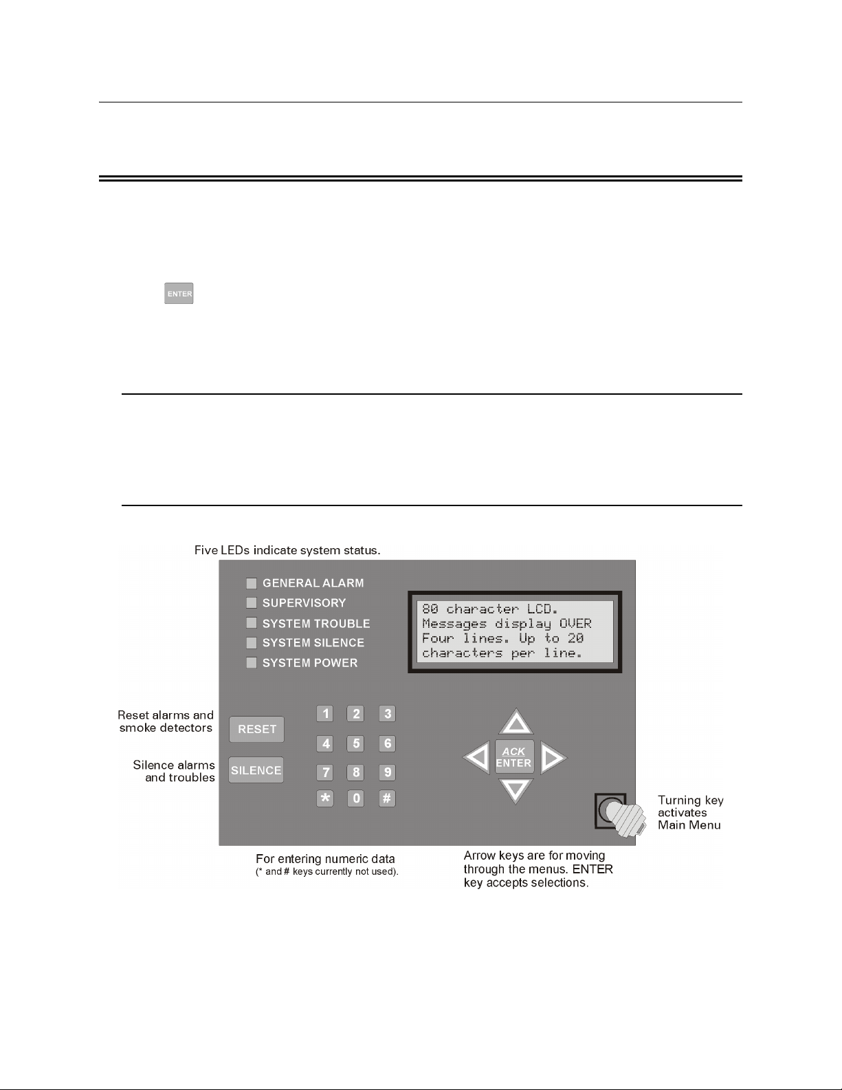
8.2 Annunciator Description
Figure 8-1shows the annunciator that is part of the control panel board assembly.
Figure 8-1 Control Panel Annunciator
151209 8-1
Page 2
IntelliKnight 5820XL Installation Manual
8.2.1 LCD Displays
The control panel LCD displays system messages, annunciates alarms, supervisories and
troubles; provides status information; and prompts for input. These messages can be up to 80
characters, displaying over four lines of 20 characters each. Annunciator keys beep when they
are pressed.
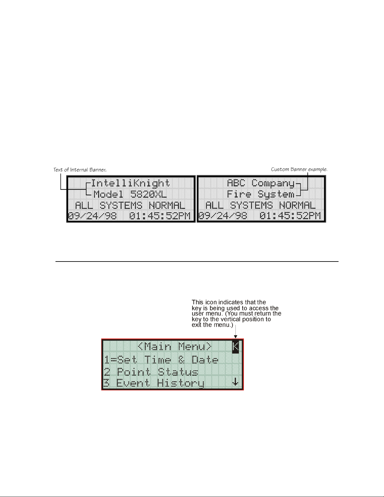
8.2.2 Banner
The banner is the message that displays on the control panel when the system is in normal
mode (no alarm or trouble condition exists and menus are not in use). You can create a
customized message that will display instead of the internal (default) message. See Section
7.6.7 for information on customizing the banner.
Figure 8-2 Banner Display Examples
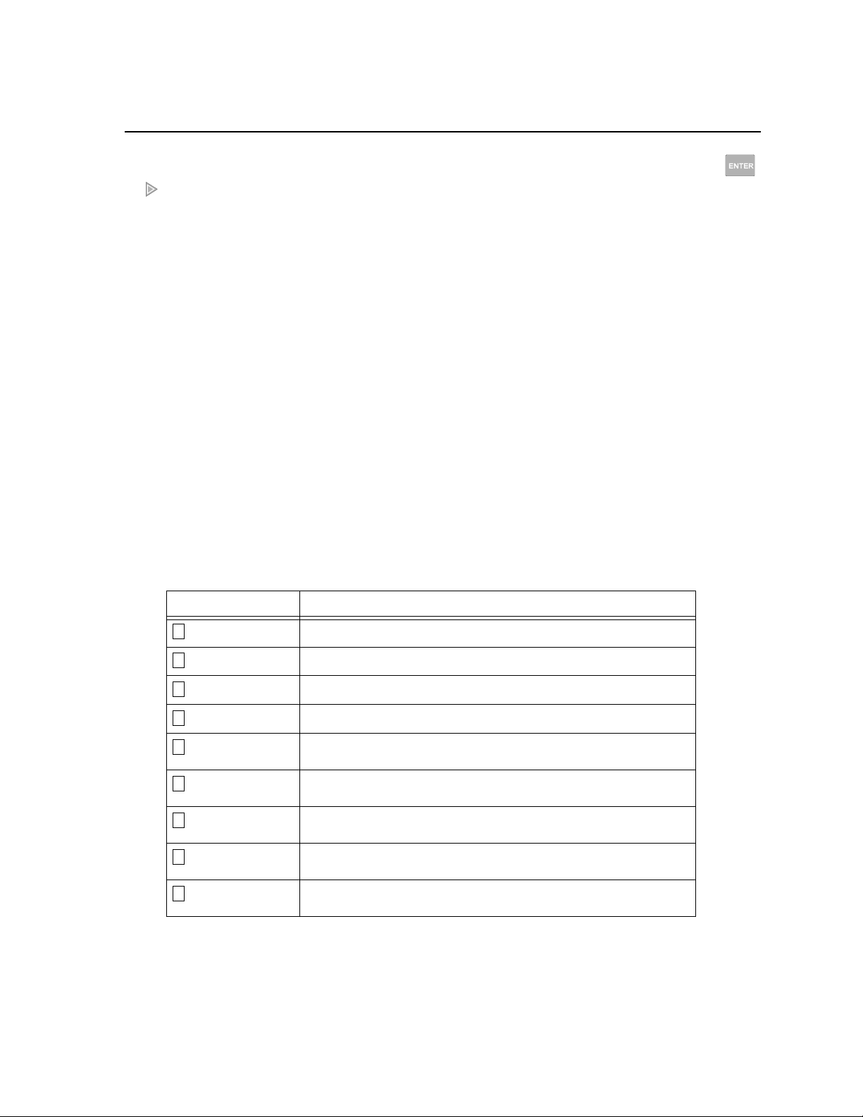
8.3 Key Operation
The key on the control panel board assembly is for accessing the Main Menu. The key is
activated when it is turned once to the right (clockwise). If the key has been used to activate
the menu, it must be turned counter-clockwise to exit the menu.
Figure 8-3 Using a Key to Access the Main Menu
8-2 151209
Page 3
System Operation
8.4 Menu System
The control panel is easy to operate from Main Menu. To view the Main Menu press the
or button on the control panel or remote annunciator, then turn the firefighter’s key
clockwise or enter your access code. The Main Menu will appear as shown in Section 8.4.1.
Select the desired option. If you have entered a code or firefighter’s key does not have access
to the menu item you have selected the following display message will appear:
-Access denied.Entered PIN does not
allow access to this
function.
You must enter an access code with the correct profile settings to gain access to that menu
item.
The control panel supports up to 20 access codes. The profile for each access code (or user)
can be modified through the programming menu option (see Section 7.9 for access code
programming).
8.4.1 Main Menu Overview
The chart below is a brief overview of the Main Menu. These options are described in greater
detail throughout this section of the manual.
Main Menu Options Description
1
System Tests
2
Point Functions
3
Event History
4
Set Time and Date
5
Printer Options
6
Reset Dialer
7
Program Menu
8
System Info
9
Up/Download
From here both menus can access Fire Drill and Indicator Test.
From here both menus can enable / disable points.
Display event history on the LCD. See Section 8.5.4 for more information.
Set time and date for the system.
Options for controlling a printer if attached to the system. If a printer is used,
the Model 5824 serial/parallel interface module must be used.
Cancel any attempt to call the central station. Any calls awaiting additional
attempts will be aborted.
Brings up a set of menus for programming the panel, including changing
access codes. These options are described in detail in Section 7.
View system information, including model and serial numbers and revision
number and date.
Initiate communication from the panel site between the panel and a
computer running the Silent Knight Software Suite.
151209 8-3
Page 4

IntelliKnight 5820XL Installation Manual
8.4.2 Using the Menus
To move through the menus:
To select an option: Enter the number of the option.
Use
previous menu.
Press (Enter key) if the option appears at the top of the menu (= symbol
displays after the option number in this case).
and to move through the options in a menu. Use to move to a
–OR–
ENTER
8.5 Basic Operation
8.5.1 Setting Time and Date
1. From the Main Menu, select for Set Date and Time.
2. Make changes in the fields on the screen. Use (right arrow) to move through the fields.
Use the and to select options in the fields.
3. When the date and time are correct, press .
8.5.2 Disable / Enable a Point
4
ENTER
1. From the Main Menu, select for Point Functions.
2. Select for Disable/Enable Point. A list of modules displays.
1
3. Use and to move through the list. Press to select the module where the
2
ENTER
point you want to disable/enable is located. A description of the point should display. The
fourth line of the screen should show "NORMAL" (meaning that the point is currently
enabled) or "DISABLED" (the point is currently disabled). Press to toggle between NORMAL and DISABLE.
8.5.3 Disable / Enable NACs by Group
1. From the Main Menu, select for point functions.
2. Select to Disable NACs by group or to Enable NACs by group.
1 2
3. Use and to move through the list of groups. Press to select the group highlighted.
2
ENTER
8-4 151209
Page 5

8.5.4 View Event History
System Operation
Use the View Event History feature to display events on LCD. From the Main Menu, press
3
to select Event History. Events will begin displaying with most recent events first.
The panel can store up to 1000 events. When it reaches its 1000-event capacity, it begins
deleting, starting with the oldest events.
If a printer is attached to the system (via a Module 5824 serial/parallel interface module), you
can print event history (see Section 8.5.17).
The 5660 SKSS or 5670 SKSS can be used to retain more than 1000 events and to create
event history reports.
8.5.4.1 To clear the event history
From the Installer menu select for System Tests. From the test menu select Clear
History Buffer.
1 6
8.5.5 Conduct a Fire Drill
1. From the Main Menu, press for System Tests.
2. Press for Fire Drill. You will be prompted to press .
1
1
ENTER
3. The drill will begin immediately after you press .
ENTER
4. Press any key to end the drill. (If you do not press any key to end the fire drill manually, it
will time out automatically after one hour.)
If a fire drill switch has been installed, activating the switch will begin the drill; deactivating
the switch will end the drill.
8.5.6 Conduct an Indicator Test
The indicator test checks the annunciator LEDs, PZT, and LCD display.
1. From the Main Menu, press for System Tests.
2. Press for Indicator Test. The system turns on each LED several times, beeping the PZT
2
as it does so. At the same time it scrolls each available character across the LCD. A problem is indicated if any of the following occurs:
• An LED does not turn on;
• You do not hear a beep;
• All four lines of the LCD are not full.
1
This test takes approximately 15 seconds to complete. You can press any key to end manually
while the test is still in progress. When the test ends, you will be returned to the <Test Menu>.
151209 8-5
Page 6

IntelliKnight 5820XL Installation Manual
8.5.7 Conduct a Walk Test
1. From the Main Menu, press for System Tests.
1
IMPORTANT!
If any alarm verification zones are being used, the user will be asked if they
wish to disable alarm verification during walk test. This occurs for either walk
test option.
2. Select for Walk Test-No Rpt. The LCD will display "WALK TEST STOPPED" on Line
3
1 and "ENTER = start test" on Line 2. If you select this option, central station reporting
will be disabled while the test is in progress.
Or
Select for Walk Test-with Rpt. The LCD will display "WALK TEST STOPPED" on
4
Line 1 and "ENTER = start test" on Line 2. If you select this option, central station reporting will occur as normal during the walk test.
The panel generates a TEST report to the central station when the walk test begins. During
a walk test, the panel’s normal fire alarm function is completely disabled, placing the
panel in a local trouble condition. All zones respond as 1-Count zones (respond when a
single detector is in alarm) during a walk test. Each alarm initiated during the walk test
will be reported and stored in the event history buffer.
3. Press to end the walk test. The system will reset. The panel will send a "TEST
ENTER
RESTORE" report to the central station.
If you do not end the walk test manually within four hours, it will end automatically.
If an alarm or pre-alarm condition is occurring in the system, you will not be able to enter the
walk test.
Note: the panel does not do a full 30 second reset on resettable power outputs. As soon as the device is back to
normal, the panel is ready to go to the next device.
8.5.8 Conduct a Dialer Test
1. From the Main Menu, press for System Tests.
2. Select for Dialer Test. The screen will display “Manual dialer test started”. When the
5
test is completed, you will be returned to the <Test Menu>.
1
8-6 151209
Page 7

8.5.9 Silence alarms or troubles
System Operation
Press and enter your code or rotate the key at the prompt. If an external silence
SILENCE
switch has been installed, activating the switch will silence alarms or troubles. If you are
already using system menus when you press , you will not need to enter your code or
SILENCE
rotate the key.
Note: Alarm and trouble signals that have been silenced but the detector remains un-restored will un-silence ev-
ery 24 hours until it is restored.
8.5.10 Reset alarms
Press and enter your code or rotate the key at the prompt. If an external reset switch
has been installed, activating the switch will reset alarms. If you are already using system
menus when you press , you will not need to enter your code or rotate the key.
RESET
RESET
8.5.11 Check Detector Through Point Status
The control panel constantly monitors smoke detectors to ensure that sensitivity levels are in
compliance with NFPA 72.
If sensitivity for a detector is not in compliance, the panel goes into trouble, generating a CAL
TRBLE condition. A detector enters a CAL MAINT state to indicate that it is approaching an
out of compliance condition (but is currently still in compliance).
When a CAL TRBLE condition occurs, the central station receives a detector trouble report
(“373” + Zone # for Contact ID format; “FT” + Zone # in SIA format).
To check sensitivity for an individual detector, follow the steps below. Section 8.5.17 provides
instructions for printing the status of all detectors in the system.
1. From the Main Menu, press for Point Functions.
2. Press for Point Status.
2
2
3. Select the module where the point you want to check is located.
4. Enter the number of the point you want to check and press .
ENTER
151209 8-7
Page 8

IntelliKnight 5820XL Installation Manual
5. A screen similar to those shown in Figure 8-4 will display.
Figure 8-4 Checking Detector Sensitivity Compliance
If a printer is attached to the system (via a Module 5824 serial/parallel interface module), you
can print detector status (see Section 8.5.17).
8.5.12 View Status of a Point
1. From the Main Menu, select for Point Status.
2. From the list that displays, press to select the module where this point is located.
The screen that displays will show you if the point has a trouble and will provide sensitivity compliance information. (See Section 8.5.11 for complete information about detector
sensitivity compliance.)
2
ENTER
8.5.13 View Alarms or Troubles
When the system is in alarm or trouble, you can press to view the location of an alarm or
trouble. See Section 8.5.13 for more information.
8.5.14 View System Information
Press from the Main Menu to view the panel model and serial number and system version
number and date. The information displays for several seconds then returns to the main menu.
8
8.5.15 Reset dialer
From the Main Menu, select . The LCD will display “Dialer reset in progress...” You will be
returned to the Main Menu when the reset is completed.
8-8 151209
6
 Loading...