

Page 1
5000
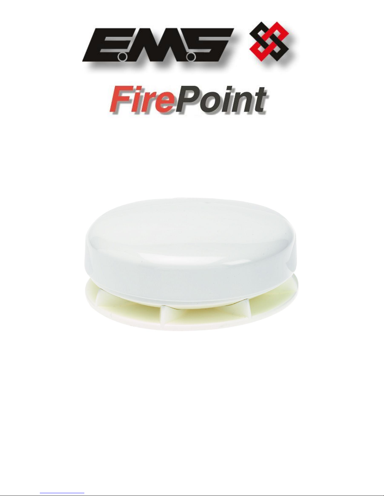
RADIO DOME SOUNDER
INSTALLATION MANUAL
Page 2

EMS 5000 FIREPOINT
©2015 EMS Security Group Ltd. All rights reserved. TSD240 Iss 3 25/06/15 AJM
2
Table of Contents
Section Page No
1. LOGGING ON A DOME SOUNDER ........................................................................ 3
2. SOUNDER VOLUME ........................................................................................... 5
3. UNIT TAMPER ................................................................................................... 6
4. DOME SOUNDER INSTALLATION ......................................................................... 7
Page 3
EMS 5000 FIREPOINT
©2015 EMS Security Group Ltd. All rights reserved. TSD240 Iss 3 25/06/15 AJM
3
1. Logging on a Dome Sounder
If the installation has been ordered as a complete system, the devices and panel will be
supplied already “pre-programmed”. In this scenario go straight to the “Sounder
Volume” section. Otherwise, when the dome sounders are purchased separately, they
must be added manually to the system. The process of adding radio devices to the 5000
FirePoint Control Panel, is largely carried out automatically, by the panel’s own operating
system. It is usual practice for each device to require “logging on” to the system. In such
cases, the following action must be taken.
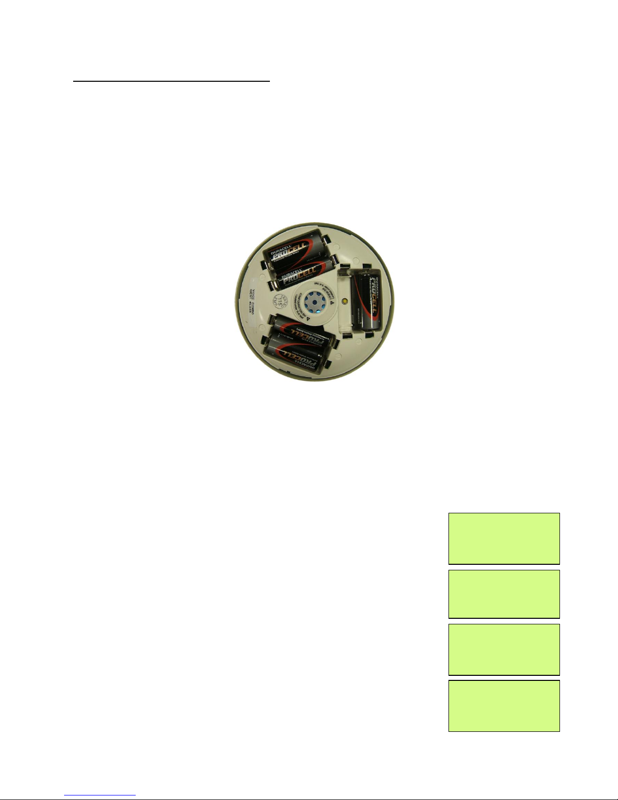
The Dome sounder is shown below, in Figure 1, with the base removed. When removing
the AA battery as shown below, the logon button is exposed.
Figure 1
The dome sounder can be programmed to the system by the following procedure:
To log the device onto the 5000 FirePoint, take the device to the front of the panel.
Insert the key into the Panels Control Key switch, located on the bottom right of the
Panel.
Step Action Screen Display
No
1 With the key in the “ON” position, the screen will
display:
2 Press the “0” key and the screen will now display:
3 Press the “” key until the screen displays:
4 Press the “YES” key and the screen will now
display:
Panel in Access
Date Time
|***Options *** * |
> Passwords <
| Time and Date |
Yes =Select Time
| Logging |
> Fire System Opts <
| Remote Access |
Yes = select Time
|** Fire system ** |
> Dev. Disable /Test<
| Net. Disable /Test |
Yes= Select Time
Page 4

EMS 5000 FIREPOINT
©2015 EMS Security Group Ltd. All rights reserved. TSD240 Iss 3 25/06/15 AJM
4
5 Press the “” key until the screen displays:
6 Press the “YES” key and the screen will now
display:
7 Press 221100 then press the “YES” key and the
screen will display:
8 Press the “” key until the screen displays:
9 Press the “YES” key and the screen will now
display:
10 Press the “YES” key to change and the screen will
now display:
11 Press the “0” key and the screen will now display:
12 Enter the slot number that you want to add a
device to (e.g. 125) then press the “YES” key and
the Screen will now display:
13 Press the “” key until the screen displays:
14 Press the “YES” key and the screen will now
display:
15 Press and hold the logon button, (as shown in
Figure 1 above), for 2-3 seconds, and the screen
will now display:
| System Mode |
>Engineers Config <
| Printer Options |
Yes= Select Time
Enter Your PIN
For Access>
Then Press YES
Time
|** Eng.; Config ** |
> Device Database <
| Sounder Options |
Yes= Select Time
| Sounder Options |
> Log On Devices <
| Site Survey |
Yes= Select Time
Logon DISABLED(000)
Push YES to change
Push NO to escape
Push YES/NO Time
|**Logon Options** |
> Logon Slot :AUTO<
| Slot is :FREE |
Yes= Select Time
Enter Device
(Numbers 1-256)
Number>
Yes= Finish Time
| **Logon Options** |
> Logon Slot :125 <
| Slot is :FREE |
Yes= Select Time
| Slot is :IN USE |
>Logon is DISABLED<
|/\/\/\/\/\/\/\/\/\/\ |
| Slot is :IN USE |
>Logon is ENABLED <
| /\/\/\/\/\/\/\/\/\/\ |
Logon Default Device
125
Yes= Select Time
Added Default Device
125
Yes= Select Time
Page 5
EMS 5000 FIREPOINT
©2015 EMS Security Group Ltd. All rights reserved. TSD240 Iss 3 25/06/15 AJM
5
16 Press the “YES” key twice and the screen will now
display:
17 Press the “NO” key three times and the screen
will now display:
Note: After logging the device on to the system there may be two faults:- 1st
fault is processor reset. 2nd fault is the Tamper. (Make sure the device tamper is
clear by stabilising the dome sounder, as explained in section 3, then press the
silence and reset buttons to clear the faults). The tamper fault will only appear
when switch 1 (Tamper Disable Switch) is set to the “Off” position, thus
enabling the tamper feature, as explained in Section 3.
18 After the faults have been cleared, turn the
control key to the “OFF” position and the screen
will display:
2. Sounder volume
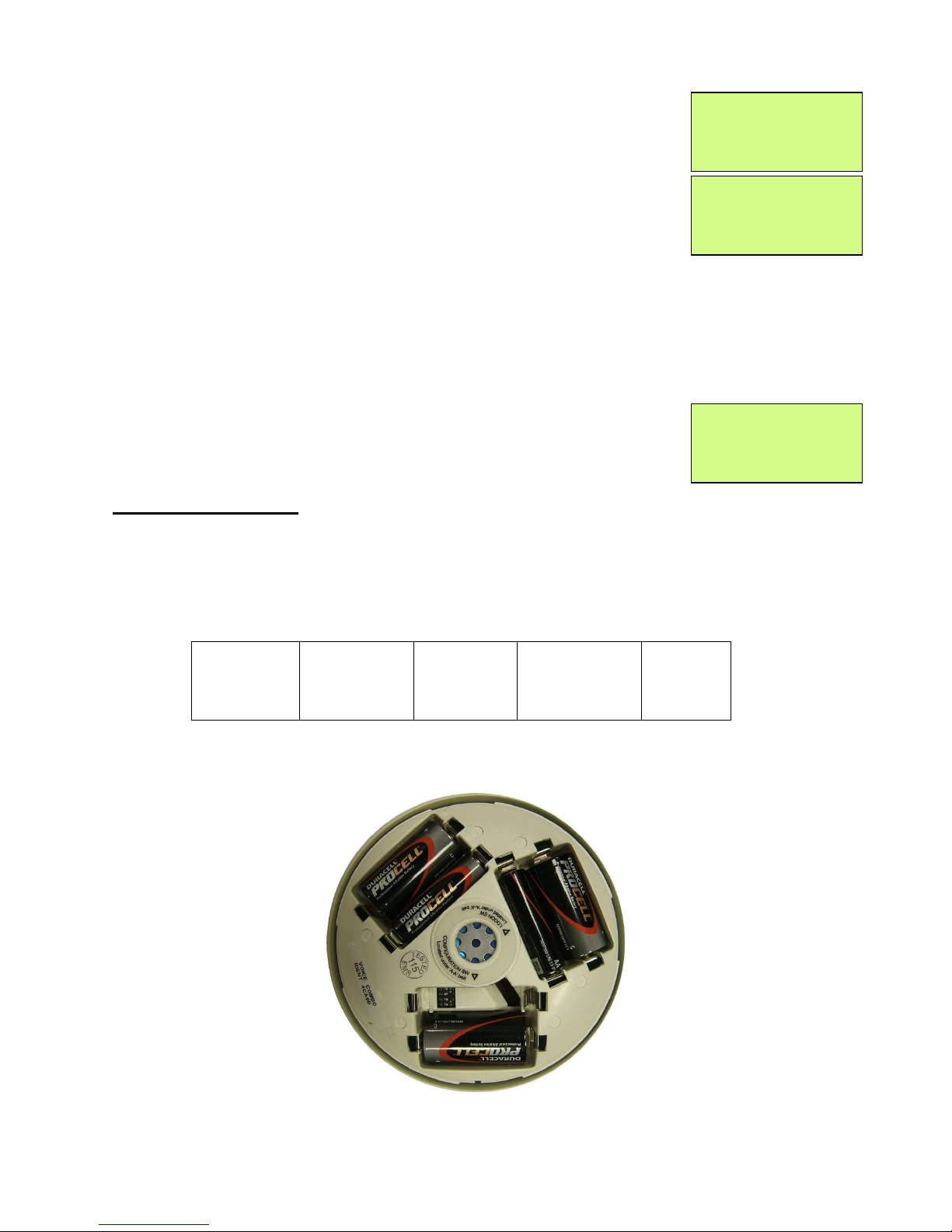
The dome’s sounder volume can be adjusted using the switches as shown below in
Figure 2.
The switch settings for the volume are dispatched as HIGH volume, with switches 3 & 4
both in the “On” position.
High
HIGH
(Default)
Medium
Low
Switch
settings
3 On, 4 Off
3 & 4 On
3 Off, 4 On
3 & 4 Off
Figure 2
Sounder switches are exposed when removing the AA battery as shown below in Figure
3.
Figure 3
| Slot is :IN USE |
>Logon is DISABLED<
| /\/\/\/\/\/\/\/\/\/\ |
01 FAULT TOT 02
Default Device 125
ZONE 01 DEVICE 125
Status Normal
Date Time
Page 6
EMS 5000 FIREPOINT
©2015 EMS Security Group Ltd. All rights reserved. TSD240 Iss 3 25/06/15 AJM
6
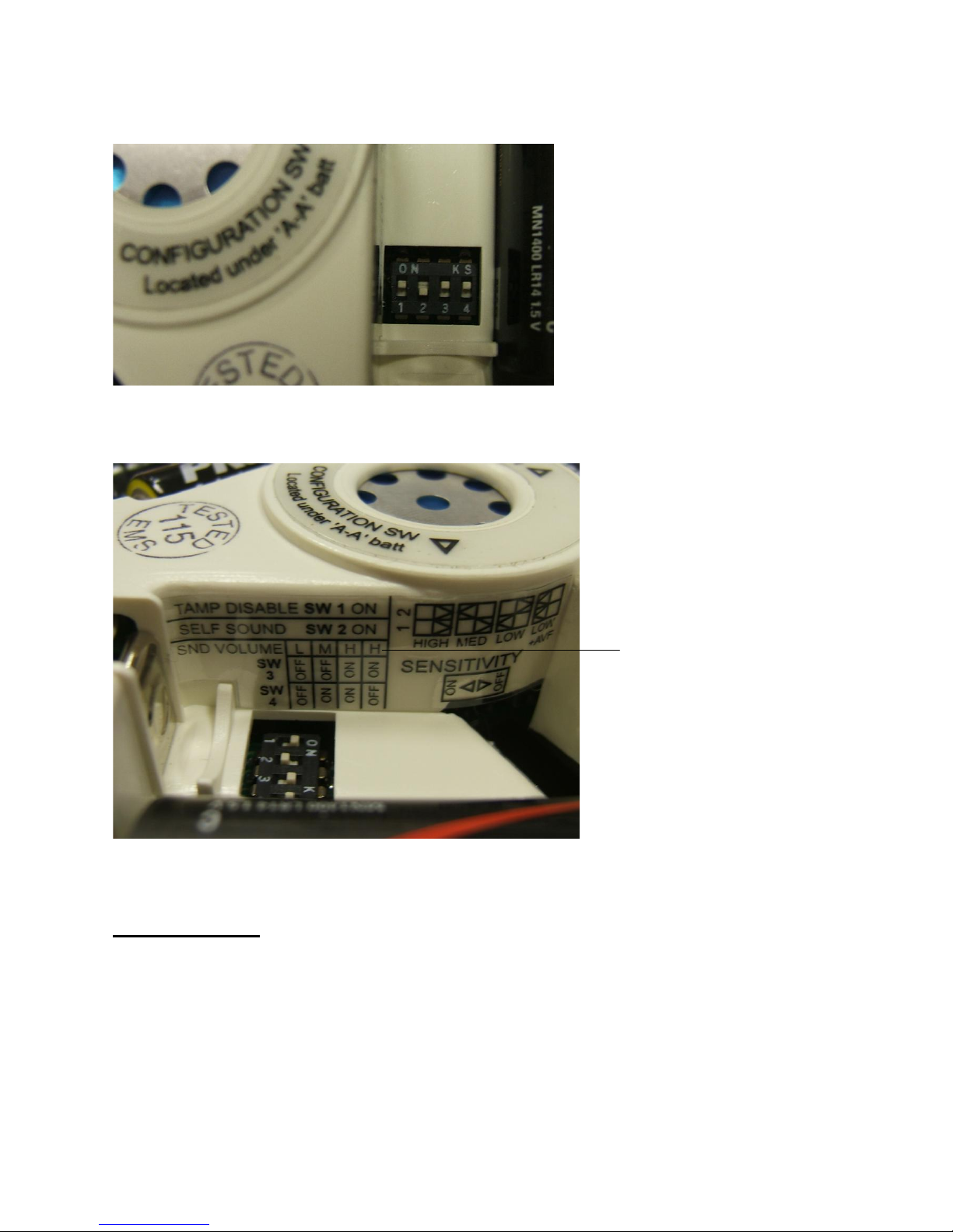
Sounder switches shown below in Figure 4.
Figure 4
Sounder Configuration Label, shown below in figure 5.
Figure 5
Note: The Sensitivity switches are not used on this model.
3. Unit Tamper
To enable the tamper facility, switch number 1 will need to be set to the “Off” position.
Alternatively, to disable the tamper facility, switch number 1 will need to be set to the
“On” position. The dome sounder has a built in tilt bottle, that once tilted, the device will
generate a tamper event. Switch number 1 is shown in Figure 5 above. (It can be seen
in the figure above that the tamper facility is disabled).
Additional protection can be made by fitting the supplied anti tamper screws.
Sounder
Dome
Configuration
Sticker
Sounder Volume
Switches (Where
the Switch in an
Upwards
orientation = the
On Position)
Page 7
EMS 5000 FIREPOINT
©2015 EMS Security Group Ltd. All rights reserved. TSD240 Iss 3 25/06/15 AJM
7
PLEASE NOTE:
Tamper Knockout
requires removal in order
to fit the Anti Tamper
Screw
4. Dome Sounder Installation
When installing, ensure all dome sounders are sited in accordance with survey and
design details.
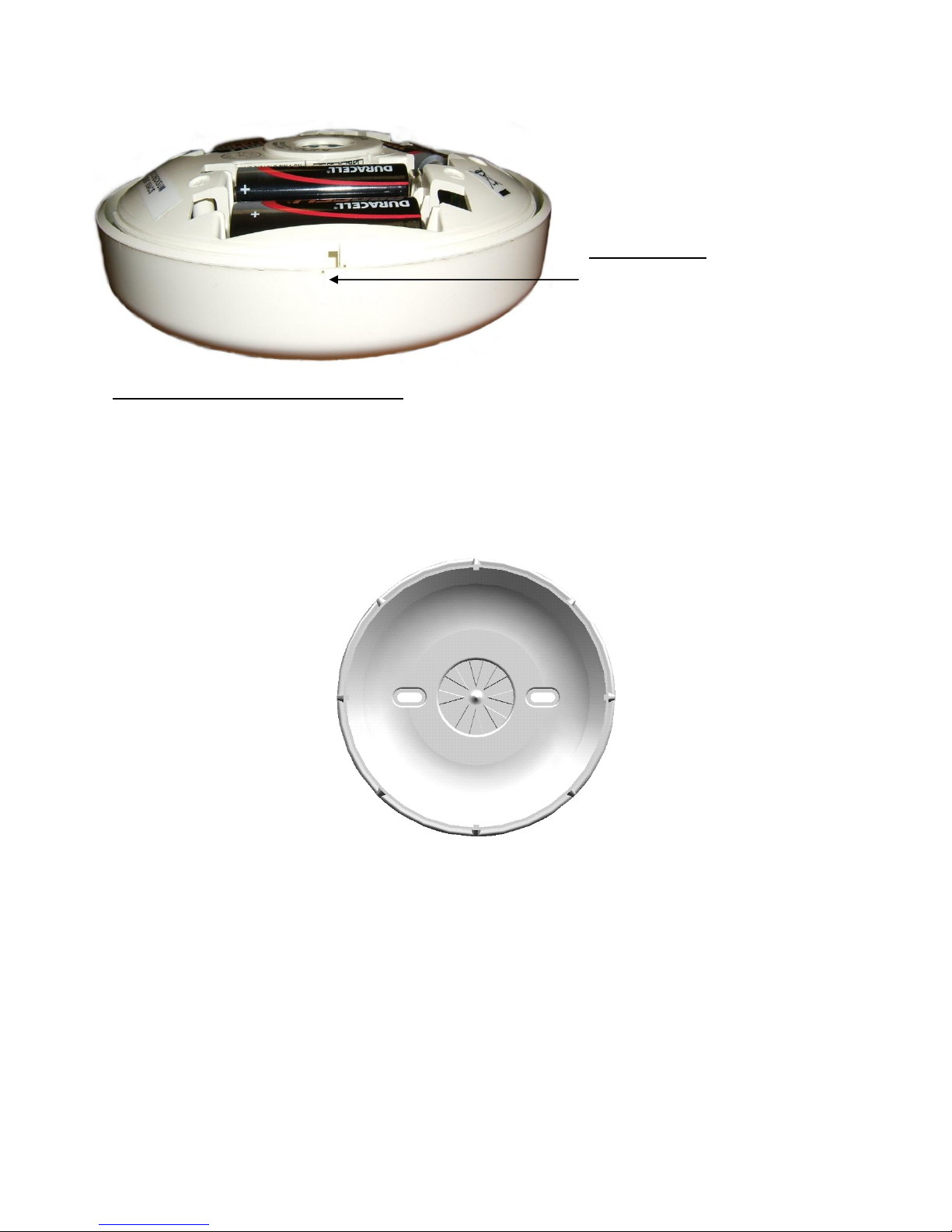
The mounting plate is shown in Figure 6. The plate can be removed by turning the
mounting plate in an anticlockwise rotation, whilst holding the sounder/dome section.
Figure 6
Affix the mounting plate to the ceiling or wall using no.8 countersunk screws with
suitable fixings. Ensure that the sounder orientation is correct, and that countersunk
head screws are used so as to prevent the possibility of damaging the internal
components.
Once the mounting plate is in place, the device can be installed to it’s location by
twisting the sounder/dome section clockwise onto the mounting plate.
Page 8

EMS 5000 FIREPOINT
©2015 EMS Security Group Ltd. All rights reserved. TSD240 Iss 3 25/06/15 AJM
8
 Loading...