

Please read this booklet and keep for future reference for the safe
installation and operation of your:
Encore
RU
RURU
RU
–––– FOR PROPERTIES OF
FOR PROPERTIES OF FOR PROPERTIES OF
FOR PROPERTIES OF
2 HECTARES OR MORE
2 HECTARES OR MORE2 HECTARES OR MORE
2 HECTARES OR MORE
FREESTANDING WOODBURNER
All installations must be in accordance
with these instructions. Consult
with the building authority having
jurisdiction to determine the need for
a permit prior to commencing the
installation.
Failure to follow these instructions may also
void your fire insurance and w
arranty.

Encore RU
2
Please complete and return your warranty registration card which is enclosed.
INDEX
Page No: Item No: Topic:
3 1 Warnings
4 2 Installation Responsibilities
4 3 Floor Protector Requirements
5 4 Installation Clearances
6 5 Assembly Instructions
7 6 Wetback Installation
9 7 Flue Installation
10 Minimum Height of Flue System
Exit
Please leave these instructions with owner when installation is complete.
Edited 6/09/12

Encore RU
3
1. WARNINGS
THIS APPLIANCE SHOULD BE MAINTAINED AND OPERATED AT ALL
TIMES IN ACCORDANCE WITH THESE INSTRUCTIONS.
The Encore RU is tested to N.Z. Standards AS/NZS 2918:2001.
If this heater is incorrectly installed a house fire may result. For your safety follow the
installation instructions carefully.
Do NOT connect the heater to a chimney serving another appliance.
Although the exterior of the heater may appear cool, contact with the unit may cause
burns, warn children and others of the possibility of injury should they touch the
heater.
Do NOT dry clothing or unseasoned wood directly in contact with the heater.
Keep all household combustible materials at least 600mm away from front of the
heater. This includes clothing, furniture, wood, newspaper, plastic, matches, etc.
DO NOT USE FLAMMABLE LIQUIDS OR AEROSOLS IN THE VICINITY
OF THIS APPLIANCE WHEN IT IS OPERATING.
Use caution when reloading with fuel. Do NOT attempt to load fuel into the heater
when the fire inside the stove is at or near its peak.
Do NOT burn large quantities of paper or combustible material that would create an
extremely hot/quick fire.
Do NOT burn highly coloured paper or brochures (junk mail).
USE ONLY DRY WOOD. AVOID BURNING WET OR GREEN WOOD.
THE USE OF SOME TYPES OF PRESERVATIVE TREATED WOOD AS A FUEL
CAN BE HAZARDOUS.
TIMBER TREATED WITH COPPER CHROMIUM AND ARSENIC TYPE
PRESERVATIVES WILL LEAVE TOXIC RESIDUES IN THE ASH, FIREBOX OR
WITHIN THE FLUE; TIMBER OFFCUTS FROM BUILDING CONSTRUCTION
WILL OFTEN CONTAIN BORIC SALTS. THE COMBUSTION OF THIS
MATERIAL OVER PROLONGED PERIODS CAN PRODUCE ADVERSE
EFFECTS ON REFACTORY LINING IN SOLID FUEL APPLIANCES. EMISSION
OF POISONOUS GASES CAN ALSO BE EXPERIENCED WITH THE BURNING
OF TREATED WOOD.
Driftwood with salt content will also cause rapid deterioration of the heater and should
not be used.

Encore RU
4
2. INSTALLATION RESPONSIBILITIES
WARNING: THE APPLIANCE AND FLUE SYSTEM SHALL BE INSTALLED
IN ACCORDANCE WITH AS/NZ 2918 AND THE APPROPRIATE
REQUIREMENTS OF THE RELEVANT BUILDING CODE OR CODES.
ANY MODIFICATION OF THE APPLIANCE THAT HAS NOT BEEN
APPROVED IN WRITING BY THE TESTING AUTHORITY IS
CONSIDERED
TO BE IN BREACH OF THE APPROVAL GRANTED FOR COMPLIANCE
WITH AS/NZS 4013.
CAUTION: MIXING OF APPLIANCE OR FLUE-SYSTEM COMPONENTS FROM
DIFFERENT SOURCES OR MODIFYING THE DIMENSIONAL SPECIFICATION
OF COMPONENTS MAY RESULT IN HAZARDOUS CONDITIONS. WHERE
SUCH ACTION IS CONSIDERED, THE MANUFACTURER SHOULD BE
CONSULTED IN THE FIRST INSTANCE.
Strict adherence to these instructions will meet these standards.
Any variation from these installation instructions or any doubt about them must be
checked against the requirements of the Standards.
Please leave this manual with the owner when installation is complete.
3. FLOOR PROTECTOR REQUIREMENTS
The heater should always be installed on top of its base due to high temperatures
sustained over long periods. The base must be anchored to both the floor protector and
the floor for seismic restraint. Anchor points are provided in the base.
If the heater is installed on or within 500mm of a heat sensitive floor, then an ash
floor protector to NZS2918 Section 2.2 will be required. This floor protector shall
extend under the appliance and not less than 300mm beyond the front of the fuel
loading or ash removal openings. The width of the floor protector shall be not less
than the width of the appliance, and shall extend not less than 200mm from each side
of the fuel loading or ash removal openings unless it forms an abutment with a wall or
heat shield at a lesser distance.
Where the floor protector consists of a number of components, it shall include a
continuous layer of heat-resistant material extending under the appliance to the
perimeter of the floor protector. All joints shall be fixed to prevent accidental
separation, and shall be sealed to prevent any spilt ash or embers contacting any heat
sensitive material.

Encore RU
5
4. INSTALLATION CLEARANCES
Firebox Size: Height 332mm
Width 412mm
Depth 330mm
Flue Size: 150mm
Heating Area estimate 160sqm
All Clearances shown are from the BASE of the Encore and not the top plate.
Dimension ‘C’ specifically is shown from the base drawer front which gives a
300mm clearance from the door opening as required under NZ2918.
CLEARANCES
A B C D E F G H J K L M N O
WITH FLUE
SHIELD
110 245 250 100 100 275 545 428 800 840 1170 970 565 500
Clearances are shown with an ash floor protector as NZ2918 Section 2.2
Encore RU
6
5. ASSEMBLY INSTRUCTIONS
1. Remove all outer packaging and timber.
2. Remove slotted steel top plates from rear of heater and set aside,
taking care not to scratch or damage the paint finishes.
3. Remove granite ashlip and door knob set from inside the firebox and
set aside, taking care not to scratch or damage it.
4. Position unit onto floor protector ensuring it complies with the
clearances as shown in section 4 on page 5.
6. If wetback fitted, plumb in the wetback in accordance with accepted
plumbing practises – refer to section 7 page 8. Ensure the wetback is not
pushed down or comes into contact with the baffle bricks or flue gas
deflectors. This will cause premature wear to the wetback and will not be
covered by the manufacturer’s warranty.
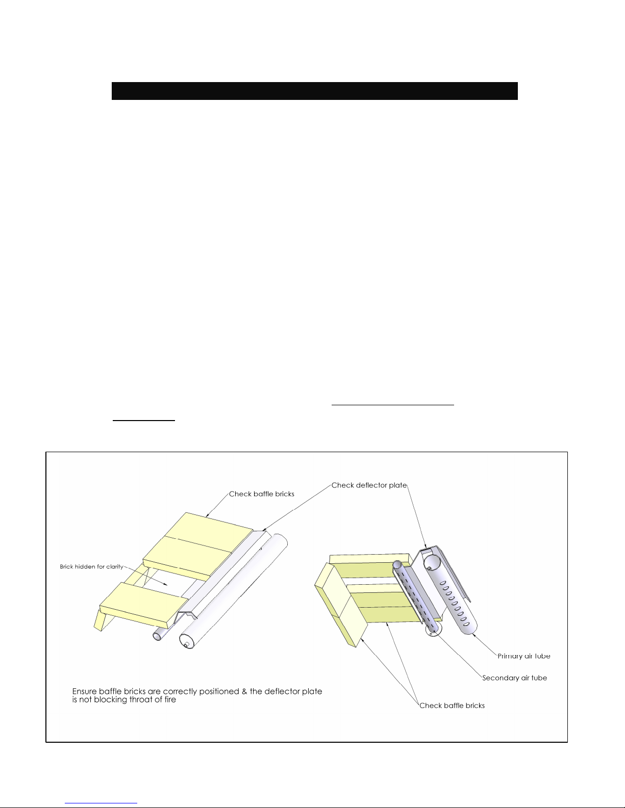
5. Lift top casting and ensure baffle bricks and metal deflector are
correctly located as diagram below with DEFLECTOR PLATE
CENTRED and then replace top casting ensuring good seal down onto fire
rope bed.
REFER ITEM 5 - CHECK BAFFLE BRICK INSTRUCTIONS

Encore RU
7
6. Assemble and install the flue as per instructions (page 9 & 10).
7. Secure both the fire and floor protector to the floor by using
appropriate fastenings through the holes provided in the rear of the base
plate. This is a New Zealand Standard 2918 requirement due to NZ being
earthquake prone.
8. A flue shield must be fitted; the minimum requirement is for a single
skin, semi-circular, stainless steel flue shield with a reflective inner
surface 1200mm high. This should be installed so that the bottom edge of
the flue shield is 20mm from the top surface of the heater and spaced off
the flue pipe by approximately 35mm.
9. Lift granite ashlip onto the two securing screws fitted to the front of
the fire under the door and tighten the two screws to secure it. (Do not
attempt to lift the fire by the ashlip).
10. Carefully position the main slotted steel painted top panel onto the
heater, there are locating feet on the underside that fit into the indents on
the cast iron tops that ensure it is correctly positioned.
Slide in the rear infill top panel behind the flue outlet
and then the curved plate locates on the outer rear edge.
11. Fit door knob set to door lever arm as drawing »»

Encore RU
8
7. WETBACK
The Encore Urban Wet is fitted with a wetback to supplement the hot water system.
WARNINGS:
DO NOT CONNECT TO AN UNVENTED HOT WATER SYSTEM.
DO NOT USE THIS FIRE WITHOUT WATER RUNNING THROUGH THE
WETBACK.
INSTALL IN ACCORDANCE WITH AS 3500.4.1 OR NZS 4603 AND THE
APPROPRIATE REQUIREMENTS OF THE RELEVANT BUILDING CODE
OR CODES.
For best performance apply the following rules:
1. Keep it simple with the shortest and straightest possible pipe run.
2. The heater should be within 6 metres of the hot water cylinder, the closer the better.
3. The flow pipe from the heater to the cylinder must rise – the cylinder should be at
least 300 mm above the water-back outlet.
4. Use only 25mm supply and return pipes.
5. Where possible the pipes should be insulated.
WARNING:
Care must be taken to protect the wetback coil and associated pipe work if being
installed in a hard/corrosive water area. Damage caused to the Wetback coil if fitted in
a hard/corrosive water area will not be covered under the manufacturer’s warranty.
Encore RU
9
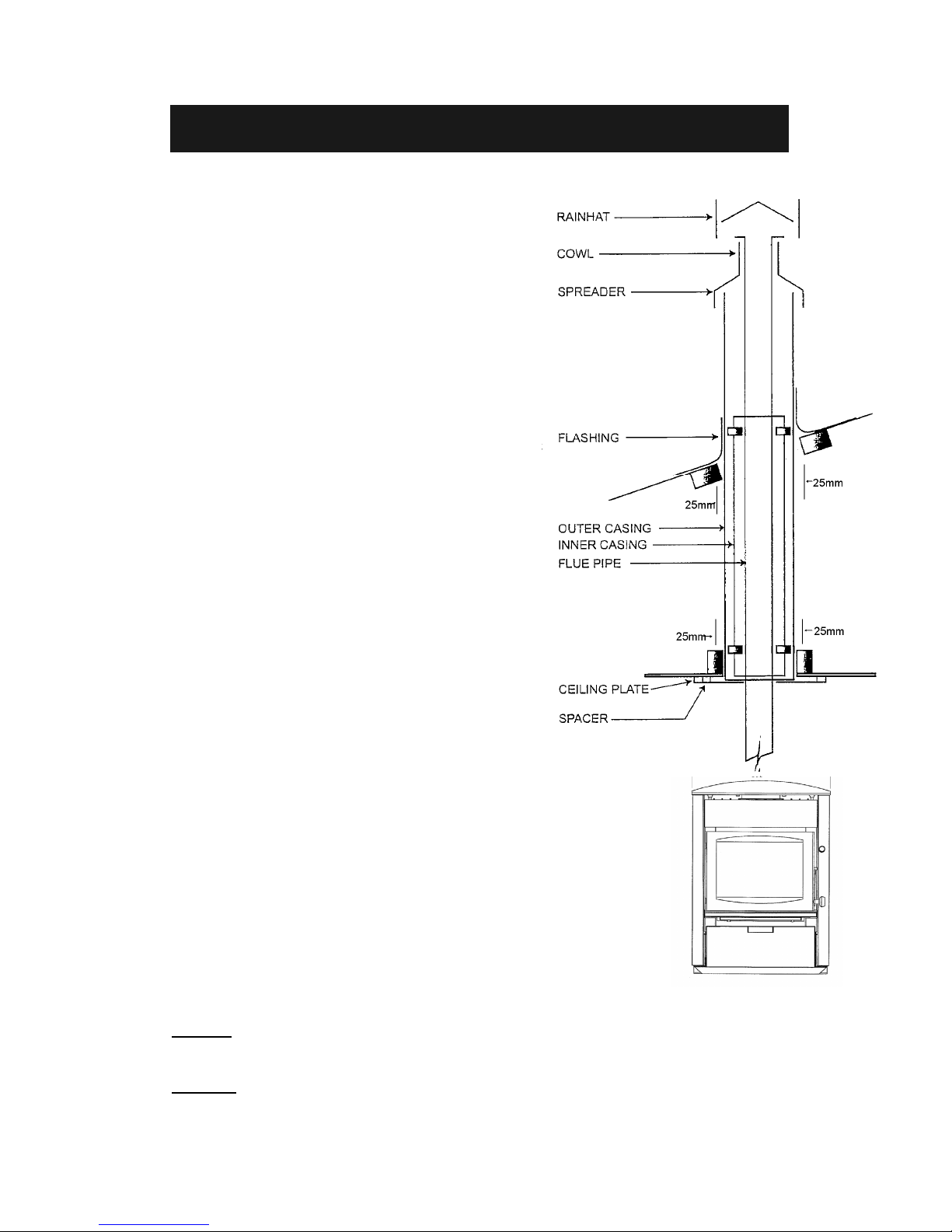
7. FREESTANDING FLUE SYSTEM
INSTALLATION INSTRUCTIONS
1. Position heater on floor protector ensuring all heater
clearances are correct as per clearances on page 5.
2. Once the location is confirmed, the appliance and floor
protector shall be fixed to the floor itself (refer to
page 6 & 7).
3. Extend a plumb line from the centre of the fire flue pipe
spigot to the ceiling. Mark position on ceiling and roof.
4. Trim hole and nog as required ensuring that a 25mm
safe clearance between combustible materials and flue
components is maintained. Fix with non combustible
spacers and screws or clouts on all four sides.
5. Cut and frame (when required) an opening in the roof,
position the outer casing through the roof until it is flush
with the under side of the ceiling, making sure as with
the ceiling there is a 25mm safe clearance between
non-combustible materials and the flue components.
Fix as in step 4.
6. Fix appropriate flashing around outer casing to the
roof to ensure a weatherproof seal.
7. Assemble flue pipe sections ensuring all seams are in
line, the assembly is straight and crimped. Ends are
pointing downwards. Fix each joint with three stainless
rivets or self-tapping screws.
8. Place ceiling plate with folded edges upwards over
heater spigot.
9. Position the flue pipe into the heater spigot. The flue
pipe can either lowered from the top as a single unit or
fed up from the room a length at a time, ensuring that
all joints are fixed properly.
10. Slide the inner casing into place, between the outer casing
and the flue pipe.
11. The flue pipe must extend 200mm above the outer casing.
Note: Extra lengths of flue pipe, inner and outer casing
may be required to achieve the minimum clearance from
the roof.
12. Slide top spreader over flue pipe down into outer and inner
casing and tighten.
13. Slide cowl over flue pipe until it rests on spreader. Secure
with rivets or self-tapping screws.
14. Fit rainhat. Do not fasten as it must be removable for flue
pipe cleaning.
15. Fix ceiling plate to ceiling maintaining an even gap all
around flue pipe.
Note: Ensure ceiling plate is spaced off from the ceiling with
ceramic spacers supplied.
CAUTION: Mixing of appliance or flue system components from different sources or modifying the
dimensional specifications of components may result in hazardous conditions. Where such action is
considered the manufacturer should be consulted in the first instance.
WARNING: The appliance and flue system shall be installed in accordance with AS/NZS 2918:2001 and
the appropriate requirements of the relevant building code or codes.

Encore RU
10

Encore RU
11
FIRENZO
WOODFIRES
BY
Hewitsons Limited
Manufacturers of:
Lady Kitchener
Bronte
Coaster
Contessa
Royale
Viking
Zealandia
Athena
Forte
Aqualux
Deco
Plaza
Kompact
98 Niven Street
PO Box 3231
Onekawa
Napier
Phone: 06 8438260
Fax: 06 8430505
Email: hothouse@firenzo.co.nz
Web: www.firenzo.co.nz
 Loading...