

Page 1
Series 1000
Heat Circulating Fireplace
Installation Instructions
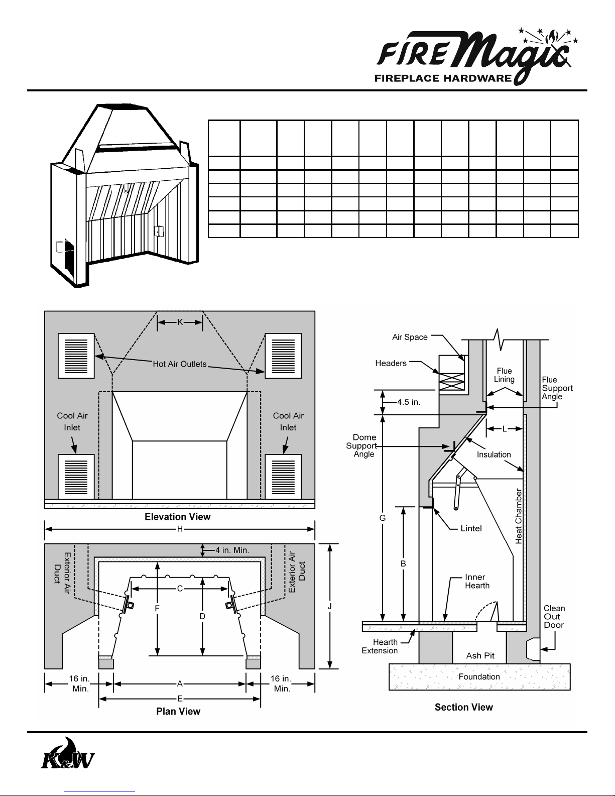
Dimensions
Heating
Model
Capacity
No.
(Cu. Ft.) A B C D E F GHMin.JMin. K L
1034A 5300 33 27 22.75 16.5 39.5 21.5 51.5 65 30 12 12
1037A 5800 36 27 25.75 16.5 42.5 21.5 51.5 68 30 12 12
1042A 6400 41 27 30.75 16.5 47.5 21.5 51.5 73 30 16 12
1048A 7600 47 29.5 36.75 20.5 53.5 25.5 55.5 79 38 20 16
1060 9500 59 29.5 48.75 24.5 67.5 29.5 65.5 91 43 20 20
1072 10600 71 29.5 60.75 24.5 79.5 29.5 65.5 103 43 20 20
Heating capacity ratings based on 20o F above zero. All dimensions are in inches unless stated otherwise.
Made from Heavy Gauge Steel
•
Poker or Optional Rotary Control
•
Conforms with IBC® & IRC
•
Insulation provided to prevent
•
masonry cracking
®
K & W Manufacturing Co., Inc., 23107 Temescal Canyon Road, Corona CA 92883
951-277-3300 Phone 951-277-2070 FAX www.k-and-w-mfg.com
Page 1 of 6
Page 2

Series 1000
Heat Circulating Fireplace
Installation Instructions
Construction Details
These installation instructions do not attempt to cover all aspects of fireplace construction. It is important to be familiar
with standard masonry fireplace construction. Fire Magic Fireplace Circulators conform to the International Building Code®
(IBC) and the International Residential Code® (IRC). HOWEVER, it is very important to check the local building codes for
any differences in your area.
Fireplace Placement:
The architecture of the room should govern the design of the fireplace. The location and size of the fireplace should be
planned to suit the size and shape of the room. The most common fireplace configuration and dimensions are shown on
page 1. Alternate configuration suggestions are made on pages 3 and 4. Please use this information when placing the
Fire Magic circulator.
The location of the air inlets and outlets of the Fire Magic circulator should also be considered when locating the fireplace
so they will blend in with the design of the fireplace and the decor of the room. Cool air inlets should always be placed
close to the floor, to pull in and heat the colder air near the floor. When a raised hearth is used, the inlets should be placed
in the hearth at floor level. Hot air outlets may be placed at or near ceiling height to preserve the beauty of the masonry.
Long horizontal runs are not recommended for either inlets or outlets.
Footings/Foundation:
The foundation size will vary with the size of Fire Magic circulator, and the placement of air inlets and outlets. Pages 1,
3 and 4 show plan and elevation views of several different configurations. Each set of views includes a chart that shows
the minimum masonry measurements. Use these plans and charts to determine the masonry “footprint” of this particular
installation.
The foundation should extend a minimum 6” beyond the masonry “footprint” on all sides. It should be 12” (or more) in
thickness, depending on local conditions. Check your local building codes. The foundation should be poured concrete or
solid masonry. It is recommended that it be reinforced with steel or mesh.
Gas Line:
A gas log lighter or gas log can be use with a Fire Magic circulator. Any gas line to supply such devices should be run
through the foundation and/or the firebrick layer of the inner hearth. Holes for a gas line should never be drilled through
the metal walls of the unit. Always follow the manufacturers' instructions when installing these devices.
Ash Pit:
An ash pit is an optional feature. Check your local building codes for what is permitted in your area. There are no special
considerations in the construction of an ash pit for a circulating fireplace. The ash pit compartment is formed within the
masonry foundation walls with clean out door for removing ashes near the bottom of the pit on an outside wall, and an ash
dump door in the floor of the inner hearth. An example of an ash pit shown in the section drawing on page 1.
Hearth:
The hearth and hearth extension should be made of concrete or masonry and reinforced to carry their own weight and all
imposed loads. There should be no combustible materials supporting or remaining against the underside of the hearth or
the hearth extension.
The hearth extension should extend a minimum of 20” in front of the fireplace and a minimum of 12” on each side. The
minimum thickness of the hearth extension should be 2”.
The inner hearth dimensions should match the size of the Fire Magic circulator. A layer of firebricks covers the concrete
or masonry base for a minimum thickness of 4”. The firebrick layer should not extend beyond the masonry face of the
fireplace. If including an ash pit, remember to leave space for the ash dump door. (See section drawing; page 1).
Continued on page 5
K & W Manufacturing Co., Inc., 23107 Temescal Canyon Road, Corona CA 92883
951-277-3300 Phone 951-277-2070 FAX www.k-and-w-mfg.com
Page 2 of 6
Page 3

Series 1000
Heat Circulating Fireplace
Installation Instructions
Alternative Configurations
The drawings on this page and the following page show alternative fireplace configurations that can be achieved
with a Fire Magic heat circulating fireplace.
Drawings and dimensions depicting a fireplace that projects into the room
with air inlets and outlets on the sides. Two elevations are shown; one
with the outlets at the level ot the unit, one with the outlets up high.
K & W Manufacturing Co., Inc., 23107 Temescal Canyon Road, Corona CA 92883
951-277-3300 Phone 951-277-2070 FAX www.k-and-w-mfg.com
Model
No. A
1034A 33 53 30
1037A 36 56 30
1042A 41 61 30
1048A 47 67 38
1060 59 79 43
1072 71 91 43
H
Min.
Min.
J
Page 3 of 6
Page 4

Series 1000
Heat Circulating Fireplace
Installation Instructions
Alternative Configurations
Drawing and dimensions depicting two
fireplaces set side by side.
...continued
Model
No. A
1034A 33 120 30
1037A 36 126 30
1042A 41 136 30
1048A 47 148 38
H
Min.
Min.
J
K & W Manufacturing Co., Inc., 23107 Temescal Canyon Road, Corona CA 92883
951-277-3300 Phone 951-277-2070 FAX www.k-and-w-mfg.com
Drawing and dimensions depicting two
fireplaces set back to back.
Model
No. A
1034A 33 65 56
1037A 36 68 56
1042A 41 73 56
1048A 47 79 72
H
Min.
Min.
J
Page 4 of 6
Page 5

Series 1000
Heat Circulating Fireplace
Installation Instructions
Construction Details
Continued from page 2
Fire Magic Circulator:
Set the Fire Magic unit on the firebrick without mortar or other material underneath. Completely cover the unit with the
insulation furnished. A thin mixture of mortar brushed on the unit will hold insulation in place. This insulation material is
important. It provides an expansion layer between the metal of the circulator and the masonry, and helps prevent cracking.
WARNING: This insulation material contains fiberglass wool. It may cause irritation to skin, eyes, and respiratory
tract. Avoid contact with eyes and skin. Protect yourself by wearing long sleeved, loose fitting clothing, gloves and
eye protection when handling and applying material. (Do not tape sleeves or pants at wrists or ankles.) As an extra
precaution, you may choose to wear a disposable dust respirator at all times. Wash with soap and warm water after
handling. Wash work clothes separately and afterwards wipe out washer.
Laying of Masonry:
Lay masonry around and to the top of the unit. (See typical construction details on page 1). The masonry walls
surrounding the circulator should be a minimum thickness of 4”. Leave channels for air passage as described in the
following section on air inlets and outlets. The masonry face (front) may be built at this time or after the chimney is
completed. Angle iron should be used in the masonry surrounding the dome for added support, and at the transition from
the masonry to the flue liner for support of the chimney and flue. The angle iron across the dome should be the same
length as the opening width of the unit, and should not extend over the air outlet openings.
Exterior Air Ducts:
Fire Magic circulators, except models 1060 and 1072, come with exterior (or combustion) air ducts built into the sides of
the units. Each duct has an 8 square inch passageway which needs to be continued through the masonry to an air intake
opening. The minimum combustibles clearance for all parts of the ducts and their passageways is 1 inch.
The exterior air intakes may not be located at an elevation higher than the firebox. The air intakes must pull the
combustion air from the exterior of the dwelling or from spaces within the dwelling ventilated with outside air such as nonmechanically ventilated crawl or attic spaces. The exterior air intakes may not be located within the garage or basement
of the dwelling. The exterior air intakes should be covered with a corrosion-resistant screen of 1/4-inch mesh.
Air Inlets and Outlets:
Channels must be left in the masonry for each inlet and outlet. All air inlets and outlets must be open to allow circulating
airflow for the Fire Magic circulator to operate correctly. Failure to allow all inlets and outlets to circulate air could result in
warping of the circulator, damage to the surrounding masonry, and voids the warranty.
The channels should be sized to fit the size of the Fire Magic circulator. If Fire Magic
air grills or fan sets are used, simply match the size of the grill-mounting frame.
When spaced masonry grilles (or some other inlet and outlet coverings) are desired,
use the table at the right for opening requirements. The two air inlets must provide
at least the net square inches of open space specified for the model unit used. The
two air outlets must provide at least the same net square inches of open space
specified. Insufficient open space allowances for air inlets and outlets will restrict
air circulation, reduce the efficiency of the fireplace, and possibly damage the unit,
Model
1034A 70 1048A 110
1037A 70 1060 120
1042A 80 1072 140
voiding the warranty. A single front outlet is possible. It must provide at least the
total square inches of open space specified. (See the drawing on page 3).
Each channel should be ”plastered” smooth to seal the walls of the channels to avoid any possible smoke and air
leakage from voids in the masonry. The “plastering” also helps improve the airflow into and out of the unit. In addition, use
additional insulation material in the joint between the masonry channel and the inlets and outlets to provide a better seal.
This step helps to prevent air from moving directly from the inlet channels to the outlet channels.
Continued on page 6
No.
Minimum
combined
sq. inch
opening
Model
No.
Page 5 of 6
Minimum
combined
sq. inch
opening
K & W Manufacturing Co., Inc., 23107 Temescal Canyon Road, Corona CA 92883
951-277-3300 Phone 951-277-2070 FAX www.k-and-w-mfg.com
Page 6

Series 1000
Heat Circulating Fireplace
Installation Instructions
Construction Details
Continued from page 5
IMPORTANT: The air from the hot air outlets is just as hot (if not hotter) as the heat produced inside the firebox. For
that reason, the combustible clearances for the hot air outlets is the same as the clearances from the fireplace opening.
Ducting the hot air directly from the outlet through any combustible materials is not recommended.
Electric Fans:
Fans are optional. The Fire Magic circulator will naturally begin to circulate hot air once the air in the heating chamber
heats up. Fans will start the air to circulate immediately, and will provide a more forceful air flow.
When fans are used, they must be used in pairs, one in each cool air inlet. Do not locate in hot air outlets. The fans
should be pulling air from the room and pushing it into the air inlet. Both fans should be wired to run simultaneously.
Fire Magic fan sets are available for two sizes of air inlets, 8 x 10 and 8 x 14. These sets include air grills with fans
mounted on the frames and a wall-mount fan control switch.
Masonry Face (front):
The construction of the fireplace face is much the same as laying the face of any other fireplace. The finished masonry
opening should be at least 1” less than the circulating fireplace opening to conceal the joint between the masonry and
metal. This joint should be packed with insulation. Remember to allow for the openings for the air inlets and outlets.
Chimney and Flue:
Chimney and flue construction is the same as any other
fireplace. Either a masonry or a metal chimney may be used
with a Fire Magic circulator. It is important to note the flue,
whether masonry or metal, must be supported by masonry
and not the metal unit. The drawing on the right depicts the
correct way to set the flue liner. When using a metal flue, the
transition from the masonry to metal is done above flue liner.
A flue of sufficient size should be used with each fireplace
unit. The standard formulas for determining flue size apply
to Fire Magic circulators. The table below gives fireplace
opening areas, and minimum flue areas from the IBC section
2113.16.1 and the IRC section R1003.15.1 to assist in
selecting the proper flue size.
Minimum Flue Net Cross
Section Area Needed
Model
No. Fireplace Opening
1034A 33 x 27 - 891 sq. inches 74 89
1037A 36 x 27 - 972 sq. inches 81 97
1042A 41 x 27 - 1107 sq. inches 92 111
1048A 47 x 29.5 - 1386.5 sq. inches 116 139
1060 59 x 29.5 - 1740.5 sq. inches 145 174
1072 71 x 29.5 - 2094.5 sq. inches 175 209
Round
Square or
Rectangular
Fire Magic circulators may be use in multi-level fireplaces,
combined in a single chimney (not a single flue). The
standard rules that govern multi-level fireplaces and
concerning flue offsets and heights apply.
Page 6 of 6
K & W Manufacturing Co., Inc., 23107 Temescal Canyon Road, Corona CA 92883
951-277-3300 Phone 951-277-2070 FAX www.k-and-w-mfg.com
 Loading...