

Page 1
Listing No. 1237
By amorales at 11:48 am, 2/28/05
INSTALLER:
These instructions must be
left with the consumer
CONSUMER:
Retain for future reference
DELUXE DROP IN SERIES
OUTDOOR GAS B ARBECUE
42,000 BTU
Brick Opening: 19-1/4" Deep (fr ont to bac k) x 24-1/4" Wide (right to left)
12" High (top to bottom) Countertop Opening
INSTALLATION AND OPERATING INSTRUCTIONS
IMPORTANT: READ THESE INSTRUCTIONS CAREFULLY BEFORE STARTING INSTALLATION
FOR Y OUR SAFETY
IF YOU SMELL GAS:
1. Shut off the gas to the appliance.
2. Extinguish any open flame.
3. Open lid if equipped with an oven.
4. If odor continues, immediately call
your gas supplier or fire department.
This appliance and its individual shutoff valves must
be disconnected from the gas supply piping
system when testing the system at pressures in
excess of ½ psig.
This appliance must be isolated from the gas
supply piping system by closing its individual
manual shutoff valves during any pressure testing
of the gas supply system at pressures up to and
including ½ psig.
WARNING: Improper installation, adjustment,
FOR Y OUR SAFETY
1. Do not store or use gasoline or other
flammable vapors and liquids in the
vicinity of this or any other appliance.
2. A propane cylinder not connected for use
shall not be stored in the vicinity of this
or any other appliance.
CODE AND SUPPL Y REQ UIREMENTS: This
barbecue must be installed in accordance with
local codes and ordinances, or in the absence
of local codes, with the latest
Code, ANSI Z223.1, or CAN/CGA-B149.1,
Natural Gas Installation Code or CAN/CGAB149.2, Propane Installation Code
National Fuel Gas
.
alteration, service or maintenance can cause
injury or property damage. Refer to this manual.
For assistance or additional information consult
qualified, professional installer, service agency
or the gas supplier.
CONTENTS
Parts List (Exploded view) Page 2
Planning for Installation P age 3
Installing the Barbecue Page 4-5
Adjusting the Barbecue Page5-6
Safety and Maintenance P age6
Use & care Page 7
Lighting Instructions Page 8
Robert H. Peterson Co. • 14724 East Proctor Avenue , • City of Industry, CA 91746
REV A 022805
1
No. L-C2-01805
Page 2
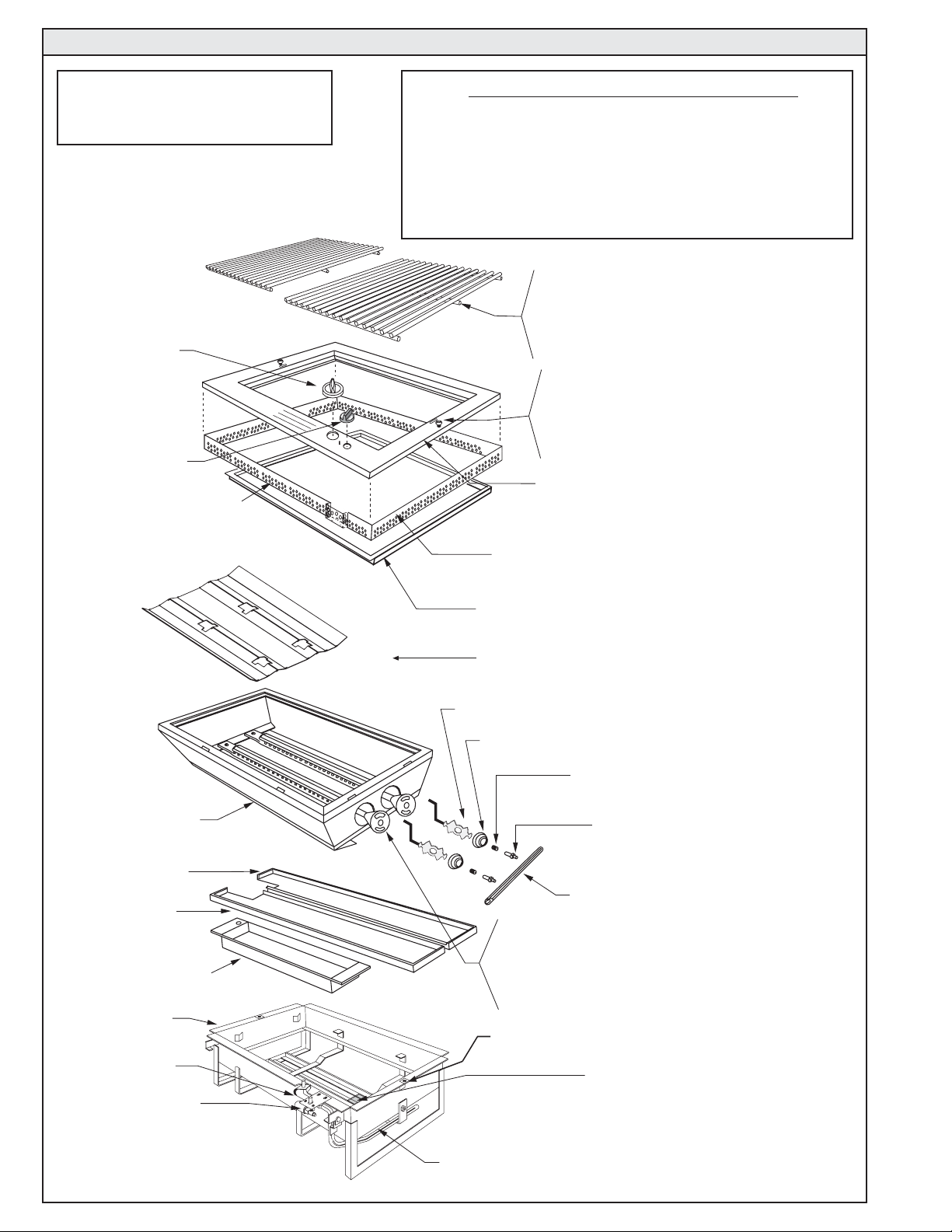
FIRE MAGIC DELUXE DROP-IN SERIES GAS BARBECUE PARTS LIST
INSTRUCTIONS FOR
FIRE MAGIC BARBECUE
MODELS NO. 3220 thru 3221
3009 Valve Knob
Deluxe (1)
3199-23-02
Ignitor Knob (1)
NOTE: EDGE OF SCREEN WITH
THE HOLES, MUST BE DOWN TO
PROVIDE VENTING.
TOOLS REQUIRED FOR INSTALLATION
• #2 (Medium) Phillips screwdriver
• Two medium size adjustable wrenches or pliers
• *3/8" wrench or 3/8" socket screwdriver
• Pipe joint compound resistant to all gases
*Note: 3/8" socket if orifice change is required.
3537-S 16"x11 1/2" Stainless Steel Rod Grids (2)
3521 16"x 11 1/2" Cast Iron Grids (2)
3528 16"x 11 1/2" Porcelainized Cast Iron Grids (2)
3537 16"x 11 1/2" Porcelainized Steel Grids (2)
3000-12 Fastener Set (Porc. Face)
3000-12-S Fastener Set (Stainless Face)
8-32 x 7/8" Screw, Finish
Washer &"U" Nut (2 sets)
3200-08 Top Panel Porcelainized (1)
or
3200-09 Top Panel Stainless Steel (1)
3200-61 Screen for Top Panel Vent (1)
3200-05
Drop-In Liner
3200-12
Rear Drip Collector,
w/Lip Stainless Steel (1)
3200-15
Front Drip Collector,
w/o Lip Stainless Steel (1)
3200-10
Drip Pan Stainless Steel (1)
3200-02
Drop-In Shell
3004
BBQ Valve
3199-01
Spark Generator w/Bracket
(1) and Knob
* Verify proper orifice for Natural or L.P Gas.
One set per unit as specified.
3200-81-0 Mounting Frame (1)
3053-S Flavor Grid Stainless steel
3201-03
Air Shutter (2)
3048-03
Spring, Air Shutter (2)
* 3001-47 Orifice, Nat. Gas (2)
* 3001-55 Orifice, Propane Gas (2)
3001-02 Orifice Holder (2)
Manifold Pipe (1)
3041-40 Cast Stainless Steel BBQ Burner (2)
3041-25 Solid Brass BBQ Burner (2)
3041-30 Porcelain Cast BBQ Burner (2)
"U" Nut Receptacle (2)
see 3000-12 or 3000-12-S
3199-15
Electrode Assembly w/Wiring &
Collector Box (1)
3902-0033
Insulation Sleeve (2) ( not shown)
3201-20 (3201-20P for Propane)
Manifold Assembly Complete w/
Valve & Orifices (1)
2
Page 3
PLANNING FOR INSTALLATION OF THE DELUXE DROP-IN BARBECUE
WHERE TO INSTALL
Y OUR BARBECUE
Fire Magic Barbecues are designed
for outdoor use only.
WARNING: Drop-in models must be installed in
masonry or other type of fireproof surroundings. This
unit is not insulated and must be installed with a
clearance from combustible materials of 18" on the
sides and the back. This appliance shall not be located
under overhead unprotected combustible construction.
With our insulating liner (Deluxe Drop-In - Part#
3200-50) you can safely install your Fire Magic Barbecue
in a wood cabinetry, stucco or other combustible
enclosure.
Do not install this unit under unprotected
flammable surfaces. Do not install or use this
appliance inside a building, garage, or any other
enclosed area including recreational vehicles or
boats.
INSTALLER NOTE: This barbecue must be installed
so that it can be removed in the event service should
be necessary. Any protrusion into the barbecue
enclosure from either side, which is less than 11 1/4"
from the counter top, may obstruct the frame and
prevent the unit from dropping into place (see "Gas
Supply Plumbing Requirements", on page 4).
INSURING PROPER COMBUSTION AIR AND
COOLING AIR FLOW
The ½" vent space between the top panel of the unit
and the counter top must be left clear with cork mounting
pads resting on counter top. Blockage of air flow
causes overheating and poor combustion. Vent screen,
part # 3200-61, is provided to cover this opening (see
vent screen installation on page 6).
VENTILATION OF ENCLOSURES
When using propane gas, take EXTREME CAUTION
to ensure ample ventilation of gas vapor. Propane gas
vapor is invisible and heavier than air. A DANGEROUS
EXPLOSION could occur, resulting in SERIOUS INJURY
OR LOSS OF LIFE, if propane gas is allowed to
accumulate and is then ignited.
Only one propane gas cylinder may be located in
an enclosure. Extra or spare cylinders must be stored
outdoors out of the reach of children and outside of any
building, garage or other enclosed area. READ AND
FOLLOW ALL WARNINGS PROVIDED WITH
PROPANE GAS CYLINDERS. Never locate a cylinder
under or near the barbecue unless sufficient
ventilation and shielding is provided to prevent any
heating of the cylinder, regulator and rubber hose.
Propane Cylinder Enclosures
To prevent invisible combustible gas from
accumulating in the cylinder enclosure, you must
provide adequate ventilation. This is accomplished by
EITHER one side of the gas cylinder enclosure left
completely open to the outside
(4) ventilation openings. Two openings are to be at the
cylinder valve level (Approx. 16” above the floor) and
at opposite walls of the enclosure. Two more openings
must be at the floor level at opposite sides of the
enclosure. The floor level openings must start at the
floor and shall extend no higher than 5” above the floor .
Each opening must have a minimum of 10 square
inches (64.5 cm
ventilation, you may drill a series of holes, omit the
grout from masonry joints or replace a brick with a
hardware cloth screen. If the floor in the cabinet is
raised and the space beneath the cabinet is open to
the outside, the lower ventilation openings may be in
the floor.
FOR YOUR SAFETY, you must provide these openings
for drainage, replacement air and cross ventilation of
any storage area exposed to possible leakage from
gas connections, the barbecue or propane gas
cylinder.
IMPORTANT: Read additional requirements for safe
use of propane gas and gas cylinders below.
HOUSEHOLD PROPANE GAS SERVICE
Consult your gas supplier for ventilation and regulator
requirements when connecting to a HOUSEHOLD
propane supply.
Note: Only Fire Magic Barbecue models with the suffix
-PA- in the model number are approved by C.S.A. for
self contained propane cylinders. Supplemental
instructions are supplied with each self contained unit.
ELECTRICAL OUTLETS
Electrical outlets in the vicinity of the barbecue, which
might be used for rotisserie motors or other appliances,
must be properly grounded.
Installer and User Note: Keep electrical supply cords
away from all heated surfaces.
2
) of free area. To achieve the proper
OR by providing four
This manual may not be copied, photocopied, reproduced, translated, or published in any electronic or
machine-readable form in whole or in part without prior written approval of Robert H. Peterson Co.
We reserve the right to amend product specifications without prior notice.
3
Page 4

EXHAUST REMO V AL
If installed under a patio roof, the cooking grid area
should be fully covered by a chimney and exhaust hood.
An exhaust fan with a rating of at least 1000 CFM may
be necessary to efficiently remove smoke and other
cooking by-products from the covered area.
Installation in fully-enclosed patio areas is not
recommended.
GAS SUPPLY PLUMBING REQUIREMENTS:
Rigid ½" black steel pipe is required to conduct the gas
supply into the barbecue enclosure for connection to
the unit. Pipe joint compound which is resistant to all
gases should be applied to all male fittings and all joints
tightened securely. Do not use pipe joint compound to
connect flare fittings.
The pipe should terminate near the front and center of
the enclosure, no more than 5" from the counter top.
Installation will be simplified if the pipe enters the
enclosure vertically from the bottom, at least 6" in from
each side and within 8" of the front wall (Figure 1).
If the pipe does not come up against the front wall, it
can easily be run along the enclosure floor and turned
up to rise within 5" of the counter top, tight against the
front wall (leaving space only to connect fittings,
Figure 2).
SAFETY NOTE: An external valve in the gas line is
necessary for safety when your barbecue is not in use.
It also provides for convenient maintenance and repair.
A removable key is recommended.
GAS SUPPLY AND MANIFOLD PRESSURE:
For Natural Gas - Normal 7" w.c. (Water Column),
Minimum 3 1/2", Maximum 10 1/2"
For Propane Gas - Normal 11" w.c., Minimum 8",
Maximum 13"
24 1/4"
BACK
STUB OUT GAS PIPE
ANYWHERE IN THIS AREA
VERTICAL PIPE
UP AGAINST FRONT
9" MIN.
12 MIN.
12"
6"
COUNTER TOP
5" MAX.
FRONT
19 1/4"
6"
Figure 1 - Top View
REAR
INSTALLING YOUR FIRE MAGIC DELUXE DROP-IN BARBECUE
Perf orm the following checks before installing y our barbecue:
CHECK BARBECUE FUEL ORIFICE SIZE
Fire Magic Barbecues are equipped with orifices for natural
gas unless otherwise indicated. For use with propane gas,
smaller orifices must be installed to avoid hazardous
overheating. The orifice size for Natural Gas is #47 (drill
size) and for Propane Gas, the orifice size is #55 (drill
size).
IF YOU ARE NOT SURE YOU HAVE THE CORRECT
BARBECUE BURNER ORIFICE SIZE
a. Remove the cooking grids and flavor grid from your
barbecue.
b. If the gas supply has been connected, make sure the
burner valve is in the 'OFF' position. Then pull the knobs
from their stems. Use a phillips screwdriver to turn the face
fastener screws counterclockwise to release the face and
remove it from the barbecue. Make sure to retain the screws
and finish washers until you are ready to reattach the face.
Note: Carefully lift the face awa y from the frame. The spark
generators for the ignition system are attached to the
inside of the face panel. The spark generator need not be
detached, but the wires must be unplugged from the
generators before the face is removed.
c. Using a flat b lade scre wdriver, pry the burner retaining
clip from rear wall of the barbecue frame (see Figure 3).
Remove the burner by; 1) Pulling it to the front of the
barbecue, 2) Lift the far end out of the notch, 3) Pull the
burner away from the manifold, taking care not to lose air
shutter and spring, which may become detached when the
burner is removed.
d. Using a 3 /8" socket, remove orifice from the orifice holder
on the burner manifold and check the number stamped on
the face (see barbecue fuel orifice size above). Repeat for
each burner as necessary.
8" MAX.
Figure 2 - View from Left
e. If your barbecue is not orificed for the gas supply you
plan to use, replace them with the orifices supplied with
the barbecue or orifices supplied by your local dealer .
f. After checking orifice drill size o r replacing the orifice,
install the air shutter spring and the air shutter over the
orifice holder fitting, between the burner and the burner
manifold, in the order and position shown in Figure 3.
g. Replace the burners in the holding groove, ensuring that
the brass orifice and orifice holder fittings project deeply
into the burners. Replace the burner retaining clips.
CONNECT THE GAS SUPPL Y TO BARBECUE
a. You will need a C.S.A. approved stainless steel flex
connector to bring the gas supply from the gas line stub to
the valve manifold. A 1/2" x 24" flex stainless steel
connector is suitable for most installations. A 1/2" female
flare fitting is required to connect to the unit. Only listed
stainless steel connectors should be used to connect the
barbecue to the gas line inside the enclosure.
CAUTION: Use only stainless steel flex connectors that
are C.S.A. listed.
WARNING: A rubber or plastic connector will
rupture or leak, resulting in an explosion or
serious injury if used inside the barbecue
enclosure.
Figure 3
BURNER
MANIFOLD WITH
SPRING
ORIFICE HOLDER
ORIFICE
BURNER CLIP
BURNER
BURNER NECK
AIR SHUTTER
4
Page 5

b. Make sure that your gas supply is turned 'OFF'.
Then connect the 1/2" pipe adapter fitting supplied with
the stainless steel flex connector to the gas supply
stub. Use pipe joint compound that is resistant to all
gasses on the male pipe fitting and tighten securely.
Do not use pipe joint compound to connect the flare
fittings.
c. Lower your barbecue into place, making sure not to
pinch or kink the gas connector. The unit may be
supported above the counter by blocks inserted under
the flanges at each side of the frame (Figure 4).
d. If the pipe does not come up against the front wall,
it can easily be run along the enclosure floor and turned
up to rise within 5" of the counter top, tight against the
front wall (leaving space only to connect fittings).
e. Connect the flex connector to the flare fitting on the
manifold inlet. Support the manifold inlet fitting with a
wrench to avoid applying excessive torque to the
manifold assembly while tightening this connection
securely. Do not use pipe compound on flare fittings.
Make sure the barbecue burner valve is in the 'OFF'
position. Turn the gas supply on. Then carefully check
all gas connections for leaks with a brush and soapy
water before lighting. NEVER USE A MATCH OR
OPEN FLAME TO TEST FOR LEAKS.
Figure 4
g. Refer to the 'Air Shutter Adjustment' instructions
below before replacing barbecue face and knobs.
FLAVOR GRID
FLAVOR GRID
LEG
BURNER
Figure 5
INST ALL THE FLAV OR GRID
Place the flavor grid directly on the burners (Figure 5).
Center the grid over the burners with the open side
up. This allows heat from the burners to be evenly
distributed throughout the cooking area. The flav or grid
heats and cools quickly, making your Fire Magic
Barbecue very responsive to the changes you specify
in grill temperature.
The flavor grid is made of stainless steel and is rust
resistant. It may be cleaned with standard oven
cleaners.
ADJUSTING YOUR BARBECUE
IMPORTANT: This barbecue will not light and will
not heat evenly or cook properly unless the air
shutters are adjusted following installation
(reference 'Air Shutter Adjustment', below).
The burner air shutters are controlled by the two wire
levers at the far right side of the cooking grill (Figure 6).
Light the barbecue in accordance with the
lighting instructions found on page 8 and burn for 5
minutes with the valves on 'HIGH' and the oven open.
WIRE LEVERS (2)
AIR SHUTTERS (2)
Figure 6
AIR SHUTTER ADJUSTMENT
After burning for 5 minutes, open the air shutters until
the flames lift off, or appear not to be touching the
burners. Then begin closing the air shutters until the
flames appear to burn while touching the burner ports
(Figure 7B). You may then see short yellow tips on the
flames. If flames are a lazy yellow, open the air
shutters until the flame is blue with yellow tipping.
manual
TAB
PARTIALLY OPEN
FIGURE 7A
CLOSED
FIGURE 7B
DIMPLE
NOTCH
(TURN TABS)
Figure 7
FLAME OFF PORTS
FLAME ON PORTS
Top View
NOTE: Barbecues in some installations achieve a
better air/gas mixture and will ignite more quickly
if the valve is first turned beyond High to Medium
or Low for lighting.
ADJUSTING THE FLAME
The barbecue valve is fully adjustable to any position
between 'HIGH' and 'LOW'. The first position is High,
the second Medium and the final Low. Flame height
can also be set anywhere between the High, Medium,
and Mow settings for all cooking requirements and
tastes.
Height of the flame with the
valve in low position
may be regulated by means of a small adjusting screw
in the center of the valve stem. This screw is accessib le
by removing the plastic valve knob which pulls straight
off the end of the valve stem.
5
Page 6

ADJUSTING Y OUR BARBECUE (cont.)
VENT SCREEN INSTALLATION
1. Take the top panel off by removing the valve and
ignitor knobs and turning the screw fasteners
counterclockwise to release.
2. Place the screen around the outside upper flange of
the shell.
3. Place the top panel over the screen and turn the
screw fasteners clockwise to tighten.
BARBECUE SAFETY AND MAINTENANCE
SAFETY INFORMATION
Every time you use your barbecue, make sure that:
1. The area around the barbecue is clear of
flammable substances such as gasoline, yard
debris, wood, etc.
2. There is no blockage of the air flow through the
vent space located below the face of the unit.
3. When using propane gas:
a. The special ventilation openings in the
enclosure are kept free and clear of debris.
b. If connected to a propane cylinder, the
rubber hose attached to the regulator is
carefully inspected before each use.
c. The propane cylinder, regulator and
rubber hose are installed in a location not
subject to heating above 125° F (51° C).
4. The burner flames burn evenly along both sides
of each burner with a steady flame (mostly blue
with yellow tipping). See 'Air Shutter Adjustment'
on page 5. If burner flames are not normal, check
the orifice and burner for insects or insect nests
(see page 4 under 'Checking Barbecue Fuel
Orifice Size', for burner removal and replacement).
5. The drip collector holes are clear and unobstructed.
Excessive grease deposits can result in a grease
fire.
6. The drip pan has been emptied.
7. The in-line gas valve or gas cylinder valve is always
shut-off when the barbecue is not in use.
DRIP COLLECTION SYSTEM
The drip collection system consists of 2 drip collectors
and a drip pan. Prior to use, lift out the flavor grid. Insert
and slide the drip pan to the far left end of the track
provided at the bottom of the frame.
NOTE: The drip pan and 2 drip collectors are designed
to be removed and replaced without removing the
burners.
Screw
Fastener
Note: Edge of screen with
the holes, must be down to
provide venting.
Figure 8
Top Panel
Screen
The flavor grids must be removed for access to the drip
collectors and pan. This should be done while the unit
is cool and the grid replaced again before lighting.
The drip collectors should be installed to rest under the
burners, in the center of the unit, on the straps above
the drip pan. The drain holes must be to the left end of
the unit, and the collector with the hooking lip should be
nearer the back of the unit and hooked over the other
collector. When properly placed, the collectors will lie
flat on the straps and direct any dripping from above or
runoff from the liner to the drip pan.
To install the collectors, they must be tilted and inserted
between the burners and under the left end of the liner
first, until they will clear the liner at the right end before
lowering to the straps and centering in place for use.
The collectors may be unhooked and pushed apart for
removal of the drip pan without removing the collectors
or burners.
PREP ARING THE BARBECUE FOR COOKING
To extend the life of your Fire Magic Barbecue, follow
these steps prior to cooking:
1. Begin by heating the unit at a normal cooking
temperature for several minutes.
2. Then open the control valve to the 'HIGH' setting
to burn off residue remaining from prior use.
3. When the barbecue has heated sufficiently, set
heat to the desired cooking level.
4. When using a smoke oven, closing the cover
during the preheat period will accelerate the
preparation process. Do not operate unattended
at high flame as cooking temperatures will quickly
be exceeded.
WARNING: Never cover the
entire
cooking or
grill surface with griddles or pans. Overheating
will occur and burners will not perform
properly when combustion heat is trapped
below the cooking surface.
CAUTION: Never spray water on a hot barbecue
as this may damage the unit.
6
Page 7

USE AND CARE OF YOUR FIRE MAGIC BARBECUE
FLAVOR FROM WOOD CHIPS OR CHARCOAL
Convenient *Fire Magic Gourmet Grilling Chips are
sold in several different popular wood types. These
chips are pre-moistened and sealed in cans which can
be opened, by lifting the tabbed lid, before placing the
entire can on the flavor grid to add natural wood smoke
flavor to the food you grill. There is no mess to clean
up. Just discard the can of ashes after there is no longer
any wood smoke aroma.
You may also add wood chips, wood chunks or the
natural wood charcoal of your choice to the flavor grid.
We recommend placing wood outside the direct
cooking zone or wrapping it in perforated aluminum
foil. Soaking wood before use will slow burning and
increase smoke flavor. Wood and charcoal ash will
remain in the flavor grid after use. The grid can be
easily removed and cleaned when the unit has fully
cooled.
CARE OF STAINLESS STEEL COMPONENTS
Your barbecue has a stainless steel oven and front
panel, the following care instructions will keep your unit
looking and working like new. Stainless steel
components are constructed of the finest prime grade
type 304 stainless steel. Meticulous attention has been
given to maintain the attractive finish throughout the
manufacturing process. Like the stainless steel used in
commercial kitchens, your barbecue requires regular
cleaning and occasional buffing to maintain its bright,
clean appearance.
Deposits of dirt and grease can be removed easily with
*Fire Magic Foaming Barbecue and Grill Cleaner.
Deposits should be removed before they are allowed
to bake onto the finish. To remove more
stubborn deposits, use a scouring pad
recommended for stainless steel. Be sure
to always rub in the direction of the polishing
lines (Figure 9). Oven cleaner may be
used, according to manufacturer's
instructions, to remove cooked-on food
deposits. Special cleaning agents and
polishing pads recommended for stainless
steel are available at your local barbecue
PETERSON'S
SINCE 1937
BARBECUE
AND GRILL
CLEANER
dealer, hardware store or supermarket.
WIPE WITH GRAIN
Figure 9 - Always rub with the grain
CAUTION: Never use ordinary steel wool or steel
brushes on stainless steel. Tiny particles left behind
may rust and stain the finish. Abrasive pads
recommended for restoring the grain in stainless steel
will, over a period of time, scratch or dull the surface of
glass or porcelain-coated products.
*Item sold by your nearest Fire Magic Dealer
BURNER MAINTENANCE
Fire Magic Burners are constructed of heavy-duty cast
stainless steel (cast brass and porcelainized cast iron
burners are also available) and will withstand many
years of outdoor use, if ordinary precautions are taken.
Once or twice a year inspect the burners and determine
if scale is building up excessively. Burners can be
removed and scraped to remove debris or scale from
ports. Spray cast iron with vegetable oil occasionally to
inhibit oxidation. Replace burners immediately if they
show any signs of weak or thin walls. Refer to the
bottom of page 4, Figure 3 for installing burners.
STAINLESS STEEL COOKING GRIDS
Fire Magic Stainless Steel Cooking Grids are finished
with a special matte (satin) finish. This special mattefinish provides a more stick-resistant cooking surface
that makes outdoor barbecuing easy and enjoyable.
And, because it is made of type 304 stainless steel,
you'll enjoy a lifetime of outdoor cooking. For best
cooking performance, follow the simple steps of 'Care
and Maintenance' after every use. Fire Magic Stainless
Steel Cooking Grids are warranted for as long as you
own them.
CARE AND MAINTENANCE (Stainless Steel Grids)
To maintain your stainless steel cooking grids we
recommend lightly brushing the grids after use with a
brass or stainless steel wire brush. Before use, brush
again if necessary and spray a light coat of vegetable
oil over the cooking surface. Discoloration or stubborn
food particles can be removed with a heavy-duty
abrasive or stainless steel scouring pad. Grills can also
be washed in an automatic dishwasher or cleaned with
strong cleaning solutions, including oven cleansers.
We do not recommend ordinary steel or wire brushes,
which may leav e tiny metal particles on the grids which
cause discoloration, but not permanent damage.
PORCELAIN COATED CAST IRON GRIDS
Fire Magic Porcelain-Coated Cast-Iron Grids are
coated with a special high-temperature porcelain in a
matte (satin) finish. This special matte-finish porcelain
coating provides a stick-resistant cooking surface that
makes outdoor barbecuing easy and enjoyable. And,
because it resists corrosion, the finish also increases
cooking grid durability to provide years of cooking
enjoyment. For best cooking performance, the wide
side of the grid bars should face up.
CARE AND MAINTENANCE (Porcelain Coated)
A spray coat of vegetable oil and light brushing with a
brass grid brush before and after use is all it takes to
maintain cooking readiness and ensure long life.
PROTECTING PARTS AND FINISH
Barbecue covers will protect the finish and extend the
life and appearance of Fire Magic Barbecues equipped
with smoke ovens. The covers are designed to protect
the finish against scratches, corrosion and oxidation.
Each cover has been cut and sewn by hand to fit a
particular smoke oven model. Flaps extend from the
sides and back. In windy areas, place weights on the
flaps or inside the sleeve on the flaps to keep the cover
from blowing off.
7
Page 8

LIGHTING INSTRUCTIONS
Follow these instructions each time you light your Fire
Magic Barbecue.
FOR AUT OMA TIC LIGHTING:
1. Read these instructions before lighting.
2. Open the lid of the smoke oven.
3. Tur n the barbecue gas valve to the 'OFF' position.
4. Turn on the gas at the source outside of the
barbecue enclosure.
5. Push the gas valve and turn to 'HIGH' then
immediately turn the ignitor knob several times in
the direction of the arrows.
CAUTION: If the b urners do not light, IMMEDIA TEL Y
turn the valve to 'OFF' and WAIT 5 MINUTES
before repeating step 5. If the burners still do not
light, refer to the instructions below for manual
lighting.
NOTE: Barbecues frequently achieve a better air/
gas mixture and will ignite more quickly if the
valve is first turned beyond High to Medium or Low
for lighting.
FOR MANUAL LIGHTING:
CAUTION: Always wait 5 minutes for gas to clear
after any unsuccessful lighting attempt.
1. Follow steps 1 through 4 above.
2. Inser t either a burning long-barrel butane lighter,
a burning long-stem match or a burning match held
by a wire extension holder (Figure 11) through the
grill to the burners below the flavor grid.
3. While holding the match or lighter flame next to
the burner, depress the valve knob and turn it
counterclockwise to the 'HIGH' position.
4. If the burner does not light, IMMEDIATELY turn the
valve to 'OFF' and WAIT 5 MINUTES before
repeating steps 2 through 4 of the manual lighting
instructions.
TO TURN OFF
TO TURN ON
PUSH
TO
TURN
Figure 11 - Match Holder
REMEMBER: FOR SAFE MANUAL LIGHTING, PLACE
A BURNING MATCH OR BUTANE LIGHTER BESIDE
THE BURNER - THEN TURN ON THE GAS (Figure 12).
Figure 12 - Manual Lighting
OFF
LOW
Figure 10
LIGHT
HIGH
TO
MED
Replacement parts may be obtained from your nearest
Fire Magic dealer. For assistance in locating a dealer
you may contact the factory at the address below.
ROBERT H. PETERSON CO.
Quality Check Date:___________
Orifice # (MAIN): __________
Orifice # (OTHER):__________ Model #: ___________
Leak Test: ___________ Serial #: ___________
Burn Test: ___________ Air Shutter: ___________
Gas Type: ___________ Inspector: ___________
Robert H. Peterson Co. • 14724 East Proctor Avenue, • City of Industry, CA 91746
NAT / PROPANE
IF YOU SMELL GAS
1. Shut off gas to the appliance.
2. Extinguish any open flame.
3. Open lid if equipped with oven.
4. If the odor continues, immediately call your
gas supplier or fire department.
8
 Loading...