

FireMagic Echelon E660i, Echelon E790i, Echelon E1060i Installation Instructions And Owner's Manual
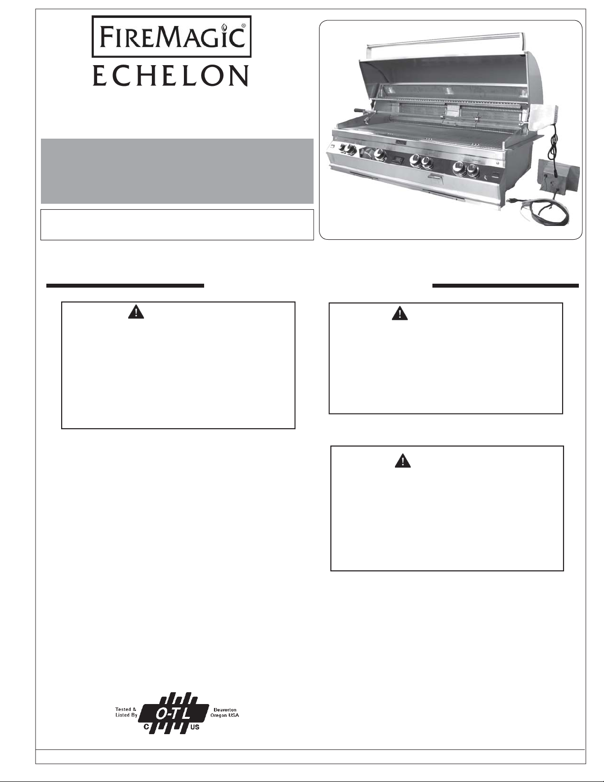
OUTDOOR BUILT-IN GAS GRILL
E660i, E790i, and E1060i
INSTALLATION
INSTRUCTIONS AND
OWNER’S MANUAL
INSTALLER: Leave these instructions with consumer.
CONSUMER: Retain for future reference.
IMPORTANT: READ THESE INSTRUCTIONS CAREFULLY BEFORE STARTING INSTALLATION OR USE.
E1060i shown
WARNINGS AND SAFETY CODES
DANGER:
IF YOU SMELL GAS:
1. Shut off the gas to the appliance.
2. Extinguish any open fl ame.
3. Open lid.
4. If odor continues, keep away from the
appliance and immediately call your
gas supplier or the fi re department.
CODE AND SUPPLY REQUIREMENTS: This grill
must be installed in accordance with local codes
and ordinances, or, in the absence of local codes,
with the latest National Fuel Gas Code (ANSI
Z223.1/NFPA 54), or Natural Gas and Propane
Storage and Handling Installation Code (CSAB149.1).
This appliance and its dedicated manual shutoff
valve must be disconnected from the gas-supply
piping system when testing the system at pressures
in excess of ½ psig (3.5 kPa).
1. Do not store or use gasoline or other
fl ammable vapors and liquids in the
vicinity of this or any other appliance.
2. An LP cylinder not connected for use
shall not be stored in the vicinity of this
or any other appliance.
Improper installation, adjustment, alteration,
service, or maintenance can cause injury
or property damage. For proper installation,
refer to the installation instructions. For
assistance or additional information,
consult a qualifi ed professional installer,
service agency, or the gas supplier.
WARNING:
WARNING:
Certifi ed to ANSI: Z21.58-2007
This appliance must be isolated from the gassupply piping system by closing its dedicated
manual shutoff valve during any pressure testing
of the gas-supply system at pressures up to and
including ½ psig (3.5 kPa).
254-B-11-5
Robert H. Peterson Co. • 14724 East Proctor Avenue • City of Industry, CA 91746
Robert H. Peterson Co. • 14724 East Proctor Avenue • City of Industry, CA 91746
REV 2 - 0810071352
All electrical outlets in the vicinity of the grill must
be properly grounded in accordance with local
codes, or, in the absence of local codes, with the
National Electrical Code, ANSI/NFPA 70, or the
Canadian Electrical Code, CSA C22.1, whichever
is applicable.
Keep all electrical-supply cords and fuel-supply
hoses away from any heated surface.
1
L-C2-28108
INSTALLATION INSTRUCTIONS ET MANUEL DU PROPRIÉTAIRE
GRIL EXTÉRIEUR D’ÎLE DE GAZ D’ÉCHELON
IMPORTANT: LISEZ CES INSTRUCTIONS SOIGNEUSEMENT AVANT DE COMMENCER L’INSTALLATION OU L’UTILISATION
SÛRETÉ ET CODES D’AVERTISSEMENT
DANGER:
SI VOUS SENTEZ LE GAZ :
1. Coupez le gaz à l’appareil.
2. Éteignez-vous n’importe quelle fl amme nue.
3. Ouvrez le couvercle si équipé d’un four.
4. Si l’odeur continue, gardez loin de
l’appareil et appelez immédiatement
votre département de fournisseur ou de
feu de gaz.
CONDITIONS DE CODE ET D’APPROVISIONNEMENT:
Ce gril doit être installé selon des codes et des ordonnances
locaux, ou, en l’absence des codes locaux, avec l’un ou l’autre
le plus défunt Code national de gaz de carburant (norme ANSI
Z223.1/NFPA 54), et Stockage de gaz naturel et de propane
et manipulation du code d’installation (CSA-B149.1).
Cet appareil et ses différents robinets d’isolement doivent être
démontés du gaz-fournissent le système siffl ant en examinant
le système aux pressions au-dessus du ½ psig (kPa 3.5).
Cet appareil doit être isolé dans gaz-fournissent le système
siffl ant par fermeture que ses différents robinets d’isolement
manuels pendant tous les essais sous pression du gazfournissent le système aux pressions jusques et y compris
le ½ psig (kPa 3.5).
• Ce gril est pour ultilisation à l’extérieur seulement.
Si l’appareil est entreposé à l’intérieur, enlever les
bouteilles et les laisser à l’extérieur.
• Ne pas ranger le gril immédiatement aprés l’avoir utilisé.
le laisser refroidir avant de le déplacer ou de la ranger.
Le non respect de cette mesure de sécurité pourrait
entraîner un incendie causant des dommages à la
propriété, des blessures ou la mort.
• Ne pas utiliser cet appareil sous une surface
combustible.
• Ne pas utiliser cet appareil sous un auvent. Le non
respect de cette mesure de sécurité pourrait entraîner
un incendie ou des blessures.
• Dégagement minimal entre les parois latérales et
l’arriére de l’appareil et la construction combustible (45.7
cm à partir des parois latérales et 45.7cm à partir de
l’arriére).
• Le régulareur de pression de gaz prévu avec cet appareil
de cuisson à gaz pour l’extérieur doit être utilisé. Ce
régulateur est réglé pour une pression de sortie de 5
pouces de colonne de l’eau pour le gaz naturel, et 10
pouces pour le propane.
• LE RÉGULATEUR INCLUS D’APPAREILS EST ÉVALUÉ
POUR LE MAXIMUM DE 1/2 (LIVRES PAR POUCE
CARRÉ). SI VOTRE OFFRE DE GAZ EST 1/2 PLUS
GRAND QUE (LIVRES PAR POUCE CARRÉ), UN
AVERTISSEMENT:
1. Ne stockez pas ou n’employez pas
l’essence ou d’autres vapeurs et liquides
infl ammables à proximité de ceci ou
d’aucun autre appareil.
2. Un cylindre de propane non relié pour
l’usage ne sera pas stocké à proximité
de ceci ou d’aucun autre appareil.
AVERTISSEMENT:
L’installation inexacte, l’ajustement, le
changement, le service, ou l’entretien
peuvent causer des dommages ou des
dégats matériels. Référez-vous à ce
manuel. Pour l’aide ou l’information
additionnelle, consultez un installateur
professionnel qualifi é, l’agence de service,
ou le fournisseur de gaz.
Toutes les sorties électriques à proximité du gril doivent être
correctement fondues selon des codes locaux, ou en l’absence
de local code, avec le code électrique national, ANSI/NFPA
70, ou le code électrique canadien, CSA C22.1, celui qui est
applicable.
Maintenez tout électrique-fournissent des cordes et carburantfournissent des tuyaux partis de n’importe quelle surface de
chauffage.
RÉGULATEUR ADDITIONNEL DOIT ÊTRE INSTALLÉ
AVANT LE GRIL. VOIR LA SECTION DE CONDITIONS
D’OFFRE DE GAZ POUR LA PRESSION APPROPRIÉE
D’OFFRE DE GAZ.
• Ne couvrez jamais la surface entière de cuisine ou de
gril de gauffreuses ou de casseroles. La surchauffe se
produira et les brûleurs ne seront pas très performants
quand la chaleur de combustion est emprisonnée audessous de la surface à cuire.
• Ne pulvérisez jamais l’eau sur une unité chaude de gaz,
comme ceci peut endommager des composants de
porcelaine ou de fer de fonte.
• Une fuite de GPL peut causer une incendie ou une
explosion si enflammée entraînant des blessures
corporelles graves ou la mort.
• Communiquez avec le fournisseur de GPL pour les
réparations ou pour disposer de qules bouteille ou du
GPL non utilisé.
Certifi é à la norme ANSI : Z21.58-2007
INSTALLATEUR : Laissez ces instructions avec le consommateur.
CONSOMMATEUR : Maintenez pour la future référence.
REV 2 - 0810071352
2
L-C2-28108
CONTENTS
4 BUILT-IN GRILL PARTS LIST
6 MODEL SPECIFICATIONS
7 GRILL SAFETY INFORMATION
7 ELECTRICAL CONNECTIONS
7 OVEN LIGHTS
8 INSTALLATION REQUIREMENTS
9 INSTALLING THE BUILT-IN UNIT
10 ELECTRICAL INSTALLATION
11 SAFE USE & MAINTENANCE OF PROPANE-GAS CYLINDERS
13 IDENTIFICATION OF GRILL CONTROLS
14 OPTIONAL POWERHOOD
17 LIGHTING (IGNITION) INSTRUCTIONS
17 SHUTTING OFF THE GRILL
18 ECHELON DIGITAL THERMOMETER
19 ROTISSERIE INSTRUCTIONS
20 OPTIONAL INFRARED BURNER OPERATION
21 ACCESSORIES
22 FIRE MAGIC
23 OPTIONAL COVER
23 CARE & CLEANING
24 REPLACING HALOGEN BULBS
25 TROUBLESHOOTING
26 CONVERTING THE GAS TYPE
28 BURNER AIR SHUTTER ADJUSTMENT
30 WARRANTY
®
DRIP TRAY
REV 2 - 0810071352
3
L-C2-28108
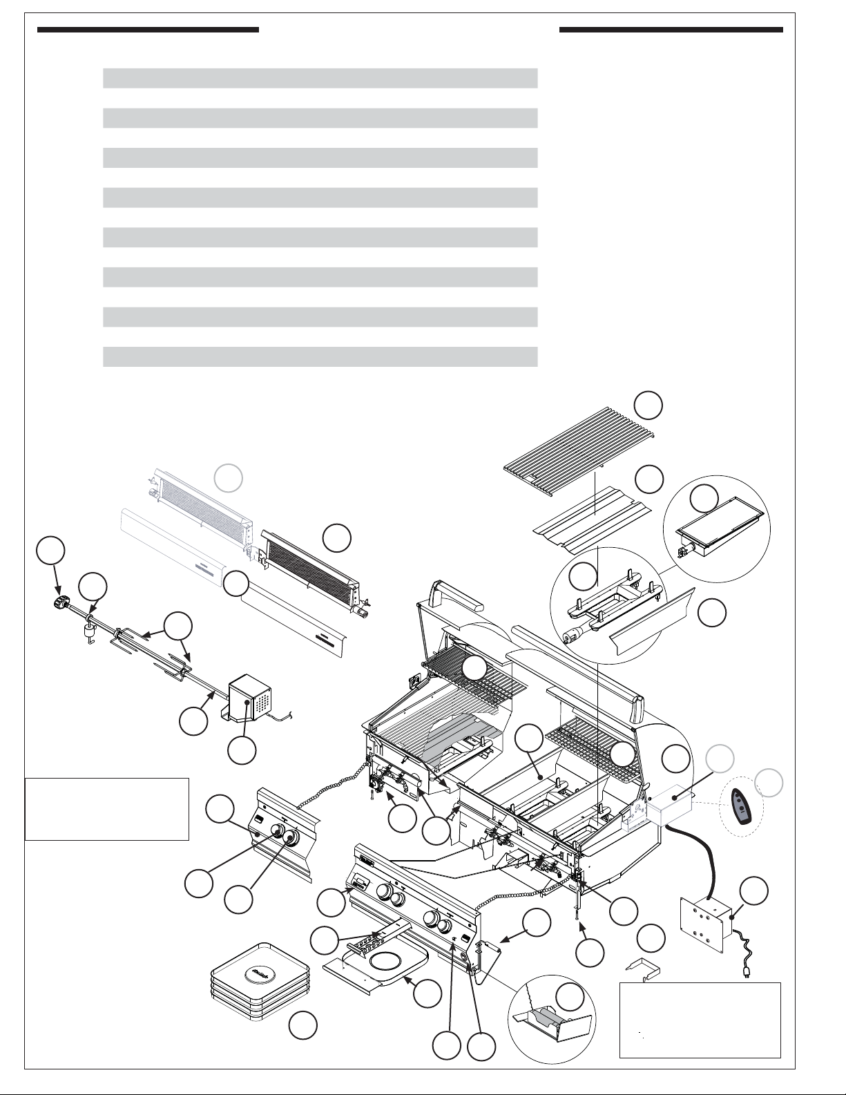
BUILT-IN GRILL PARTS LIST
Item Description
1 Stainless cooking grid set
2 Flavor grid
3 Main burner
4 Infrared burner
5 Oven lid
6 Warming rack
7 Backburner right/main
8 Backburner left
9 Backburner cover
10 Heavy-duty motor
11 Heavy-duty rod
12 Heavy-duty rod knob
13 Meat holder
14 Counterbalance
15 Grid lifter
16 Convertible regulator
†
12
14
13
Items in light gray are
not available on all
models.
11
18
† Available only on E1060i models
‡ Not shown
8
2
4
7
1
9
3
31
6
32
10
6
5
33
35
ON
16
OFF
17
Fig. 4-1
REV 2 - 0810071352
19
20
26
21
32
23
22
37
15
40
25
36
34
24
4
To order replacement
parts, contact your
local Fire Magic
dealer.
L-C2-28108
®
BUILT-IN GRILL PARTS LIST (Continued)
Item Description
17 Valve manifold
18 Control panel
19 Small knob
20 Large knob
21 Digital thermometer
22 Meat probe
23 Power supply w/connector
Thermometer. batt. pack (3v), Wire harness,
24
Thermocouples
25 Drip tray
26 Drip tray liner (set of 4)
27 Wire harness assembly‡
28 Ignitor ‡
29 Light Lense ‡
30 Haolgen Bulb ‡
31 Zone separator
32 Smoker drawer
33 Power Hood motor assy.
34 Power Hood switch
35 Power Hood remote
36 Light control switch
37 Light microswitch
38 Flex connector ‡
39 Fire Magic® cookbook ‡
40 Support screw
†
†
†
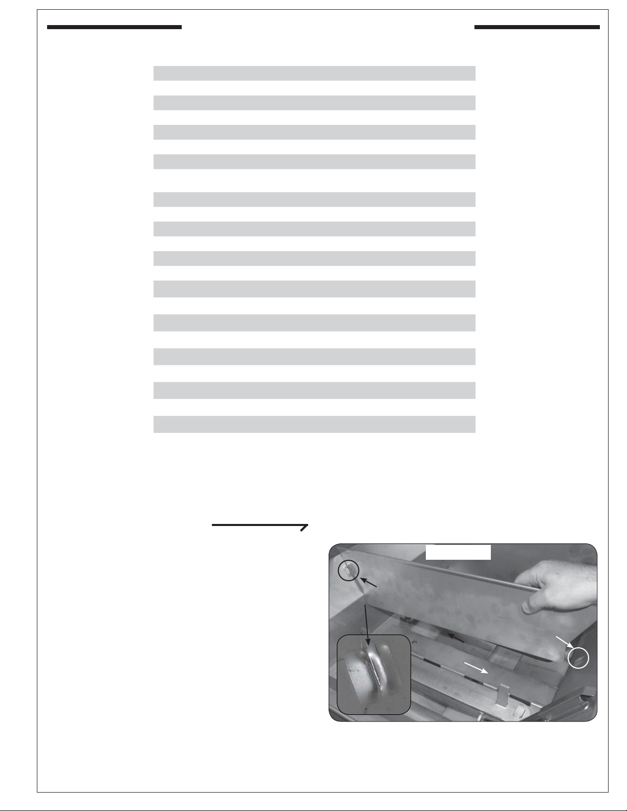
INSTALL ZONE DIVIDERS
Place the zone dividers as shown (Fig. 5-1)
into the grooves in the inner fi rewall of the grill to
allow for maximum heat control and thermometer
accuracy in each zone. Remove and store during
rotisserie use.
REV 2 - 0810071352
5
Groove
Fig. 5-1
Zone divider
Groove
Front
L-C2-28108
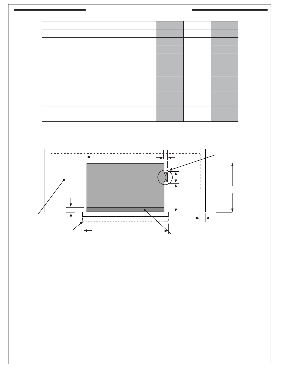
MODEL SPECIFICATIONS
Fire-Magic® Model Specifi cations Table
Table 1 E660i E790i E1060i
Countertop to unit bottom (cut-out)* 12" 12" 12"
Side to side (noncombustible cut-out)* 31-1/4" 37" 50"
Front to back (noncombustible cut-out)* 23-1/2" 23-1/2" 23-1/2"
Control panel width 32-1/2" 38-1/4" 51-1/4"
Fig. 6-1
Main burner BTU
N/P orifi ce drill size
Backburner BTU
N/P orifi ce drill size
Smoker drawer burner BTU
N/P orifi ce drill size
Infrared searing burner BTU
N/P orifi ce drill size
*Note: If using an insulating liner, consult liner instructions for counter cut-out
dimensions.
25,000
#42/#54
19,000
#49/#57
2,500
#68/#77
24,000
#45/#55
32,000
#38/#53
23,000
#44/#56
2,500
#68/#77
24,000
#45/#55
28,000
#40/#53
15,000
#51/#58
2,500
#68/#77
24,000
#45/#55
TOP VIEW
Extra cut-out for
Side to side
1-1
/4"
Power Hood only!
NON-COMBUSTIBLE
CABINET CUT-OUT
DIMENSIONS
2 3/4"
10"
Front to back
11"
Countertop
Control
Panel
Countertop overhang
Control panel width
Lower support
REV 2 - 0810071352
6
L-C2-28108
GRILL SAFETY INFORMATION
1. The outdoor grill and surrounding area MUST
remain clear of fl ammable substances such as
gasoline, yard debris, wood, etc.
2. The airfl ow through the vent space located below
the control panel must remain unobstructed.
4. The fl ames on each burner burn evenly along
the entire burner with a steady fl ame (mostly
blue with yellow tipping). If burner fl ames are not
normal, check the orifi ce and burner for insects
or insect nests. Adjust the air shutter as needed
(see AIR SHUTTER ADJUSTMENT)
3. When using propane gas:
5. The in-line gas valve or gas cylinder valve must
a. The required ventilation openings in the
always be shut OFF when the grill is not in use.
enclosure must be clear of debris.
6. The drip collector holes must be clear and
b. The propane cylinder, regulator, and rubber
hose must be in a location not subject to
unobstructed. Excessive grease deposits can
result in a grease fi re.
temperature above 125° F (51° C).
7. The backburner or IR burner cover must be
removed before using the burner.
WARNING: NEVER cover the entire cooking or grill surface with griddles or pans. Overheating will occur, and
burners will not perform properly when combustion heat is trapped below the cooking surface.
CAUTION: NEVER spray water on a hot gas unit.
Important: When reviewing this units wiring connections; please refer to the wiring diagram
label affi xed to the inside of the control panel.
ELECTRICAL CONNECTIONS
OVEN LIGHTS
To turn on the oven lights, open the oven, then push
This grill requires 110 volt AC power to operate.
the button on the far right of the grill control panel
(see SUPPLIED ITEMS list) until it clicks.
Use a grounded electrical extension cord rated for
outdoor use to connect the grill to line power.
The lights will automatically turn off when the oven
door is closed and then turn on again when it is
reopened (much like the light in your refrigerator.)
If the lights do not come on, check your electrical
WARNING
connection.
Electrical Grounding Instructions
For your protection against shock hazard, this
outdoor-cooking gas-appliance is equipped with
a three-pronged (grounding) electrical connector.
This appliance should be connected to a properly
grounded three-prong receptacle using a grounding
extension cord rated for outdoor use. Do not cut or
remove the grounding prong from the connector.
REV 2 - 0810071352
7
L-C2-28108
INSTALLATION REQUIREMENTS
This grill is designed for outdoor use only. DO NOT use this grill under unprotected fl ammable surfaces.
DO NOT use this grill inside a building, garage, enclosed area, or an unprotected covered area (see
EXHAUST REMOVAL below). DO NOT use this grill in or on a recreational vehicle or boat.
Important: The grill must have a minimum of 20" (50.7 cm) right, left, and back clearance from unprotected
combustible construction. If installing this grill in a combustible surround, the correct R. H. Peterson
insulating liner must be used.
The control panel MUST remain removable for servicing
(see PARTS LIST).
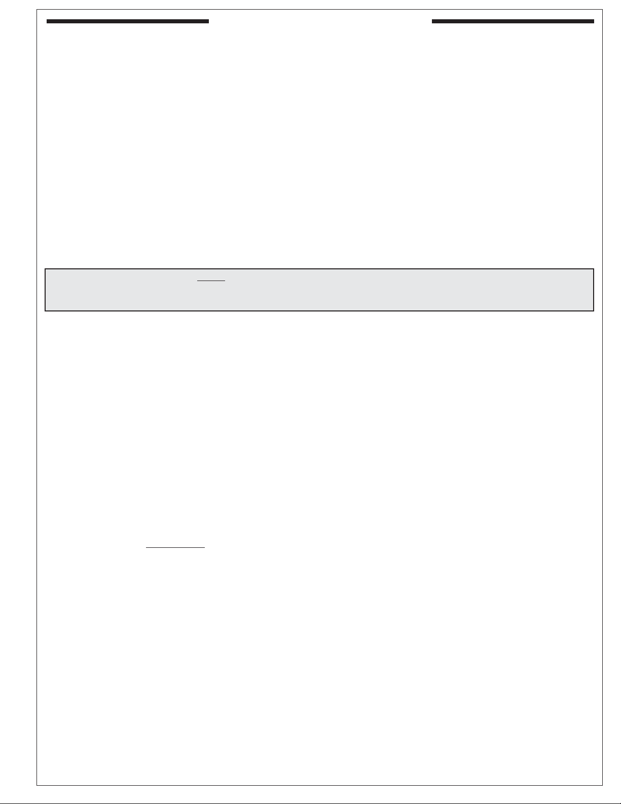
ENSURING PROPER COMBUSTION AIR AND
COOLING AIRFLOW
Proper airfl ow (Fig. 8-1) MUST be maintained for the
grill to perform as it was designed. If airfl ow is blocked,
overheating and poor combustion will result. Do not
block the 1" (2.5 cm) front air inlet along the bottom of
the control panel or more than 75% of the cooking grid
surface with pans or griddles.
Note: The 1" (2.5 cm)
front air space
also allows
access to the
drip tray.
Fig. 8-1 - Ventilation diagram
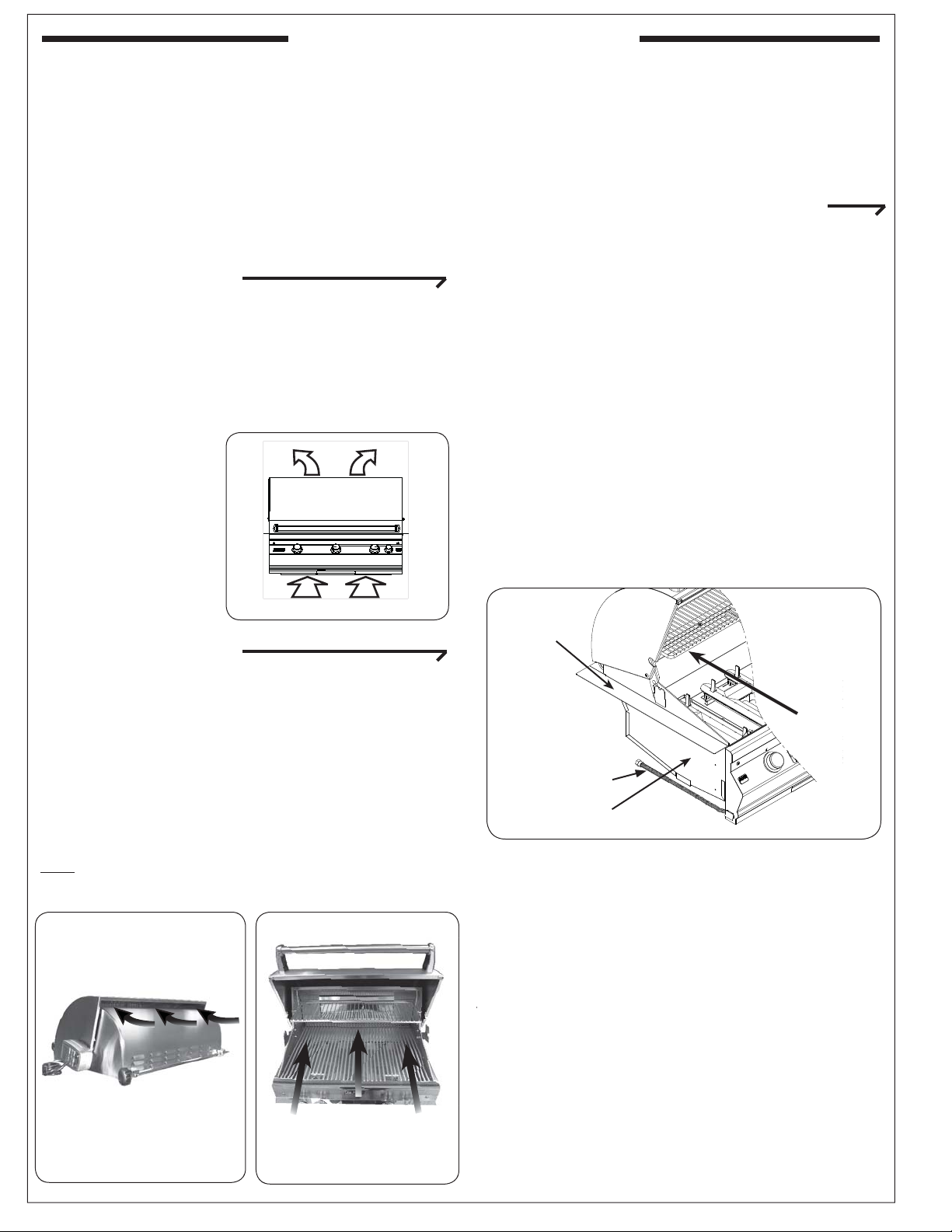
EXHAUST REMOVAL
If installed or used under a patio roof, the cooking grid
area must be fully covered by an exhaust hood with a vent.
An exhaust fan with a rating of 1,000 CFM (cubic feet per
minute) (472 liters per second) or more may be necessary
to effectively remove smoke and other cooking by-products
from the area under the hood. Fire Magic Vent Hoods
(models 42-VH and 60-VH) are available to meet this
requirement. This grill must not be used under unprotected
overhead combustible construction. THIS UNIT MUST
NOT BE LOCATED IN A FULLY ENCLOSED AREA
OF ANY KIND.
INCORRECT
Rear oven lid vent
CORRECT
GAS-SUPPLY PLUMBING REQUIREMENTS
For natural gas or a household propane system, rigid
1
/2"
(1.3 cm) or 3/4" (1.9 cm) black steel pipe or local codeapproved pipe is required to conduct the gas supply to
the unit. Contact your local gas supplier. Connect this
pipe to the required C.S.A.-approved stainless-steel fl ex
connector (attached). An NPT adapter has been provided
1
for
/2" pipe. DO NOT use a rubber hose within the grill
enclosure. Apply only joint compounds that are resistant
to all gasses to all male pipe fi ttings except fl are fi ttings.
Make sure to tighten every joint securely.
Note: If 1/2" (1.3 cm) pipe is used with natural gas,
it should be no longer than 20' (6.1 meters).
Important: An external valve (with a removable
key) in the gas line is necessary for
safety when the grill is not in use. It also
provides for convenient maintenance.
Left-side
hanger
Orient grill
so prevailing
wind blows
this way.
Flex connector
Left-side
support wall
CAUTION: Wind blowing into or across the rear
oven lid vent (Fig. 8-2) can cause
poor performance and/or dangerous
overheating. Orient the grill so that the
prevailing wind blows toward the front of
the grill (Fig. 8-3).
Fig. 8-4
YOU MUST PROTECT
REAR OVEN VENT FROM
PREVAILING WIND
Fig. 8-2
REV 2 - 0810071352
PLACE GRILL SO PREVAILING
WIND BLOWS TOWARD FRONT
OF GRILL
Fig. 8-3
CAUTION: To prevent dangerous overheating, the rear
of the unit must have a minimum clearance
of 8" (20.3 cm) from any backsplash/wall.
GAS SUPPLY AND MANIFOLD PRESSURES:
For natural gas - normal 7" (17.78 cm) water column
(w.c.), minimum 5" (12.7 cm), maximum 10 1/2" (26.7
cm). For propane gas - normal 11" w.c., minimum 10"
(25.4 cm), maximum 13" (33 cm).
8
L-C2-28108
OFF
Dedicated manual shut-off valve
To gas
system
Cut-out
Countertop
Hanger
Flex
connector
Gas inlet pipe
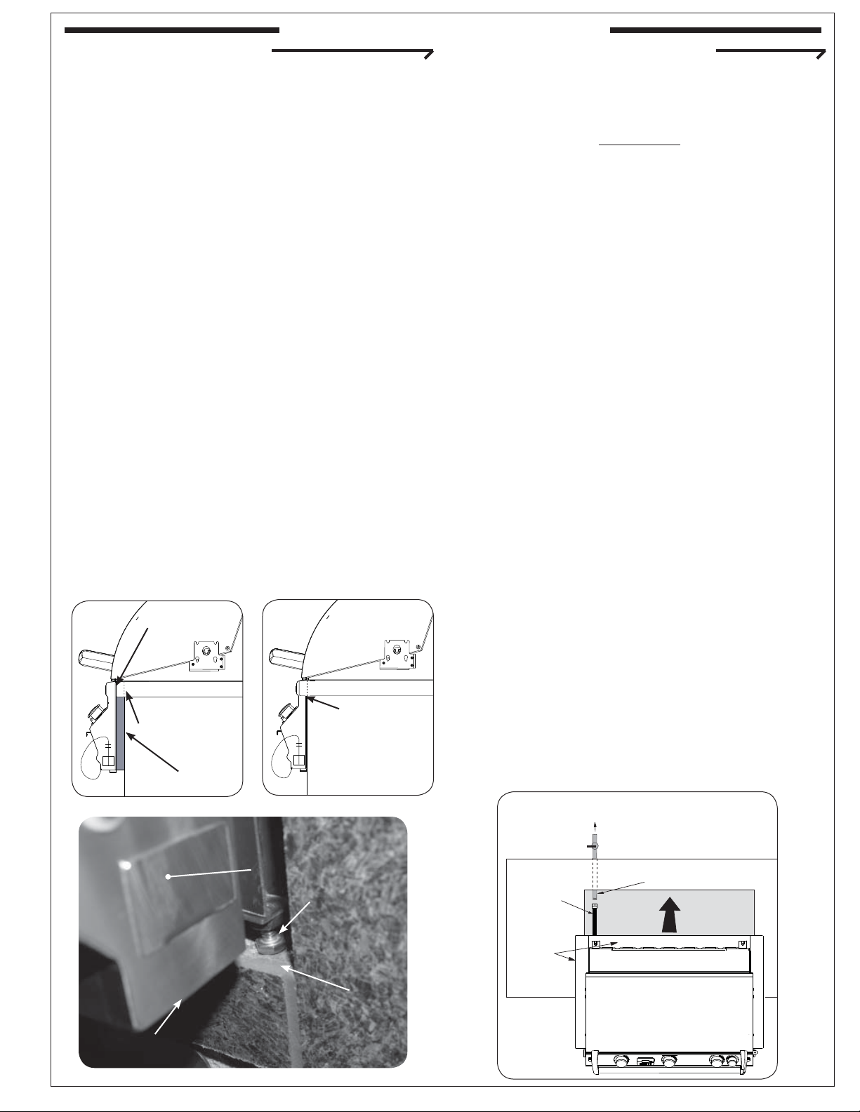
COUNTER PREPARATION
INSTALLING THE BUILT-IN UNIT
CONNECTING THE GAS SUPPLY
Consult Table 1 for non-combustible enclosure cutout dimensions. A Robert H. Peterson insulating
liner must be used if the counter or any supporting
construction is combustible. Consult the instructions
that come with the liner for dimensions and
additional installation information before beginning
the installation.
This outdoor built-in grill must supported by the
stainless-steel hanger extending from the upper
portion of the grill. The hanger rests on the left, right,
and back of the countertop and on the two front
structural supports with attached adjustable screws
located below the control panel on the left and right
sides (see Fig. 9-3).
The control panel is designed to sit fl ush against
the cabinet face (see Fig. 9-2). If the countertop
extends beyond the cabinet face, creating a
countertop overhang (see Fig. 9-1), it must be
cut fl ush with the cabinet face where the for the
width of the control panel or a gap will be created
exposing the forward portions of the left and right
side fi re walls.
Note: It is not necessary to remove the control
panel or knobs to install this unit.
control panel
stops here
CAUTION: Use only C.S.A. listed stainless-steel
fl ex connectors within the enclosure.
WARNING
A rubber or plastic connector will rupture or
leak, resulting in an explosion or serious injury
if used inside the appliance enclosure.
a. Run the attached fl ex connector routed under
the left side of the grill out of the enclosure and
to the gas stub.
b. Turn OFF the gas supply at the source. Then
connect the
1
/2" pipe adapter fi tting supplied
with the stainless-steel fl ex connector to the
gas-supply stub. Use pipe joint compound that
is resistant to all gasses on the male pipe fi tting
and tighten securely. DO NOT use pipe joint
compound to connect fl are fi ttings.
d. Turn all burner control knobs to the OFF position.
Turn the gas supply on. Then carefully check
all gas connections for leaks with a brush and
half-soap/half-water solution before lighting.
NEVER USE A MATCH OR OPEN FLAME TO
TEST FOR LEAKS.
e. Close the dedicated gas-supply shut-off valve,
then slide the grill into place. Do not to pinch,
kink, or damage the gas connector line.
Countertop Countertop
Proposed cutout in overhang
GAP CREATED
Fig. 9-1
Bottom of
face
Battery
door
Overhang
IDEAL
Flush-mounted
control panel
Fig. 9-2
Adjustable
support
screw
Bottom
of cut-out
opening
Fig. 9-3
f. Rotate the adjustable support screws to the left
to raise and to the right to lower the respective
side of the appliance grill. Use a
7
/16" open-end
wrench as needed.
Important: Do not extend the support screws
so far that any part of the hanger
is raised off the counter top.
Fig. 9-4
REV 2 - 0810071352
9
L-C2-28108
 Loading...