

Page 1
DELUXE DROP-IN SERIES
OUTDOOR GAS BARBECUE
INSTALLATION AND OPERATING
INSTRUCTIONS
INSTALLER: Leave these instructions with consumer.
CONSUMER: Retain for future reference.
Important: READ THESE INSTRUCTIONS CAREFULLY BEFORE STARTING INSTALLATION OR USE.
SAFETY WARNINGS & CODES
DANGER
IF YOU SMELL GAS:
1. Shut off the gas to the appliance.
2. Extinguish any open fl ame.
3. Open lid if equipped with an oven.
4. If odor continues, keep away from the
appliance, and immediately call the gas
supplier or the fi re department.
CODE AND SUPPLY REQUIREMENTS: This
barbecue must be installed in accordance with
local codes and ordinances, or, in the absence of
local codes, with either the latest National Fuel Gas
Code (ANSI Z223.1/NFPA 54), or Natural Gas and
Propane Storage and Handling Installation Code
(CSA-B149.1).
This appliance and its individual shutoff valves must
be disconnected from the gas supply piping system
when testing the system at pressures in excess of
½ psig (3.5 kPa).
This appliance must be isolated from the gas supply
piping system by closing its individual manual
shutoff valves during any pressure testing of the
gas supply system at pressures up to and including
½ psig (3.5 kPa).
WARNING
1. Do not store or use gasoline or other
fl ammable vapors and liquids in the
vicinity of this or any other appliance.
2. A propane cylinder, not connected for
use, shall not be stored in the vicinity of
this or any other appliance.
WARNING
Improper installation, adjustment, alteration,
service, or maintenance can cause injury or
property damage. Refer to this manual. For
assistance or additional information, consult
a qualified professional installer, service
agency, or the gas supplier.
All electrical outlets in the vicinity of the barbecue
must be properly grounded in accordance with local
codes, or, in the absence of local codes, with the
National Electrical Code, ANSI/NFPA 70, or the
Canadian Electrical Code, CSA C22.1, whichever
is applicable.
Keep all electrical supply cords and fuel supply
hoses away from any heated surface.
REV 2 - 0809241402
Listing No. 1237
Robert H. Peterson Co. • 14724 East Proctor Avenue • City of Industry, CA 91746
1
L-C2-01808
Page 2
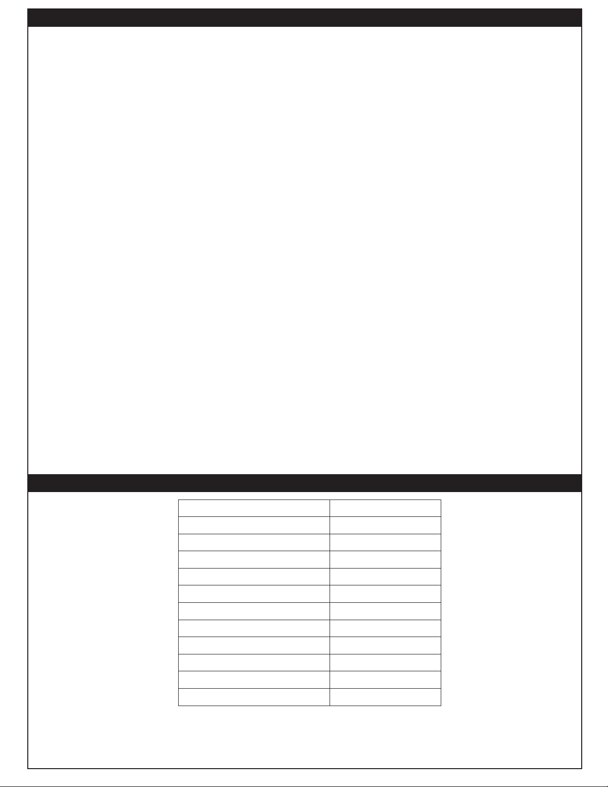
TABLE OF CONTENTS
PRODUCT DATA TABLE 2
PARTS LIST 3
PLANNING FOR INSTALLATION 4
ENSURING PROPER COMBUSTION AIR AND COOLING AIR FLOW 4
ELECTRICAL OUTLETS 4
EXHAUST REMOVAL 4
GAS SUPPLY PLUMBING REQUIREMENTS 4
INSTALLATION 5
CHECK BARBECUE FUEL ORIFICE SIZE 5
CONNECT THE GAS SUPPLY TO BARBECUE 5
INSTALL THE FLAVOR GRID 5
SAFE USE & MAINTENANCE OF PROPANE-GAS CYLINDERS 6
CHECKING AND CONVERTING GAS TYPE 7
CHECKING AND CONVERTING THE REGULATOR 7
AIR SHUTTER ADJUSTMENT 8
MAIN BURNER AIR SHUTTER ADJUSTMENT 8
BARBECUE SAFETY INFORMATION & MAINTENANCE 9
DRIP COLLECTION SYSTEM 9
LIGHTING (IGNITION) INSTRUCTIONS 10
ELECTRONIC LIGHTING 10
MANUAL LIGHTING 10
REPLACING THE IGNITOR BATTERY 11
TROUBLESHOOTING 11
ACCESSORIES 12
THE GRILL BRUSH (OPTIONAL) 12
THE COOKING GRID LIFTER 12
THE DRIP PAN 12
THE FLAVOR GRID(S) 12
THE WARMING RACK 12
CARE & CLEANING 13
COVER 13
FIRE MAGIC
®
OUTDOOR GAS GRILL LIMITED WARRANTY 14
PRODUCT DATA TABLE
Specifi cation Value
Counter opening height* 12" (30.5 cm)
1
Counter opening width* 24
Counter opening depth* 19
Main burner
BTU per burner \
Natural gas orifi ce
Propane gas orifi ce
Infrared burner (if equipped)
BTU per burner
Natural gas orifi ce
Propane gas orifi ce
Table 1 - Product data table
*Note: If using an insulating liner consult liner
instructions for counter cut-out dimensions.
/4" (61.2 cm)
1
/4" (48.3 cm)
42,000 (12.4 kw)
(2.184 mm)
#44
#55 (1.321 mm)
28,000 (8.2 kw)
(1.511 mm)
#53
#58 (1.067 mm)
REV 2 - 0809241402
2
L-C2-01808
Page 3
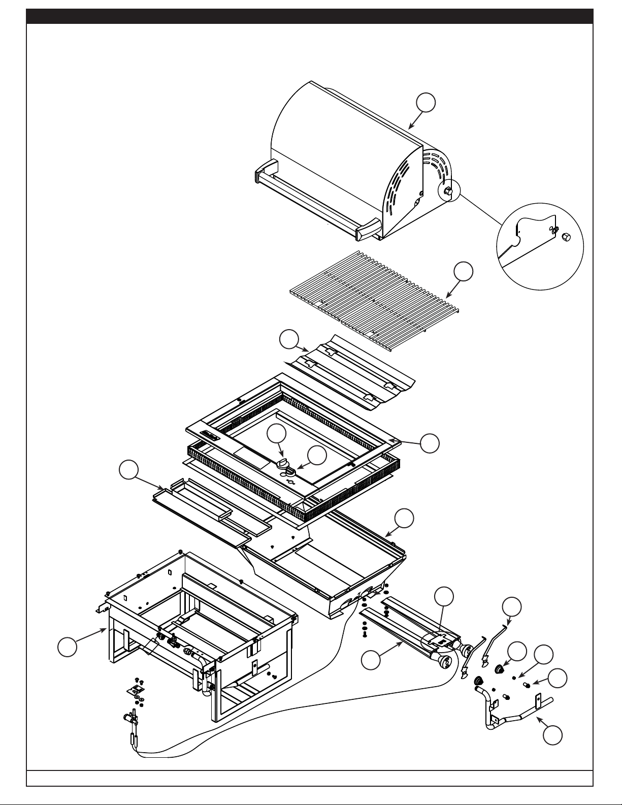
Item Description
1. Valve knob
2. Ignitor knob
3. Flavor grid
4. Drop-in liner
5. Drip tray
6. Drop-in shell
7. Pair of air shutters
8. Pair of steel burners
9. Pair of air shutter springs
10. Pair of orifi ces (natural)
or Pair of orifi ces (propane)
11. Pair of orifi ce holders
12. Manifold assembly
13. Top control panel
14. Stainless steel grid
15. Oven assy. (optional)
16. Electrode assy with wiring
PARTS LIST
15
14
Replacement parts can be ordered
from your local Fire Magic dealer.
5
3
1
13
2
4
16
7
6
REV 2 - 0809241402
8
9
Fig. 3-1
Robert H. Peterson Co. • 14724 East Proctor Avenue • City of Industry, CA 91746
3
10
11
12
L-C2-01808
Page 4
PLANNING FOR INSTALLATION
WHERE TO INSTALL THE BARBECUE
Fire Magic barbecues are designed for outdoor use only.
WARNING
Drop-in models must be installed in masonry or other
type of fi reproof surroundings. This unit is not insulated
and must be installed with a clearance from combustible
materials of 18" (45.7 cm) on the sides and the back.
This appliance shall not be located under unprotected
overhead combustible construction.
With our insulating liner, you can safely install the Fire
Magic barbecue in a wood cabinetry, stucco, or other
combustible enclosure.
Do not install this unit under unprotected fl ammable
surfaces. Do not install or use this appliance inside
a building, garage, or any other enclosed area,
including recreational vehicles or boats.
Note: This barbecue must be installed so that it can
be removed in the event service should be
necessary. Any protrusion into the barbecue
enclosure from either side, which is less than
1
/4" (28.2 cm) below the countertop, may
11
obstruct the frame and prevent the unit from
dropping into place.
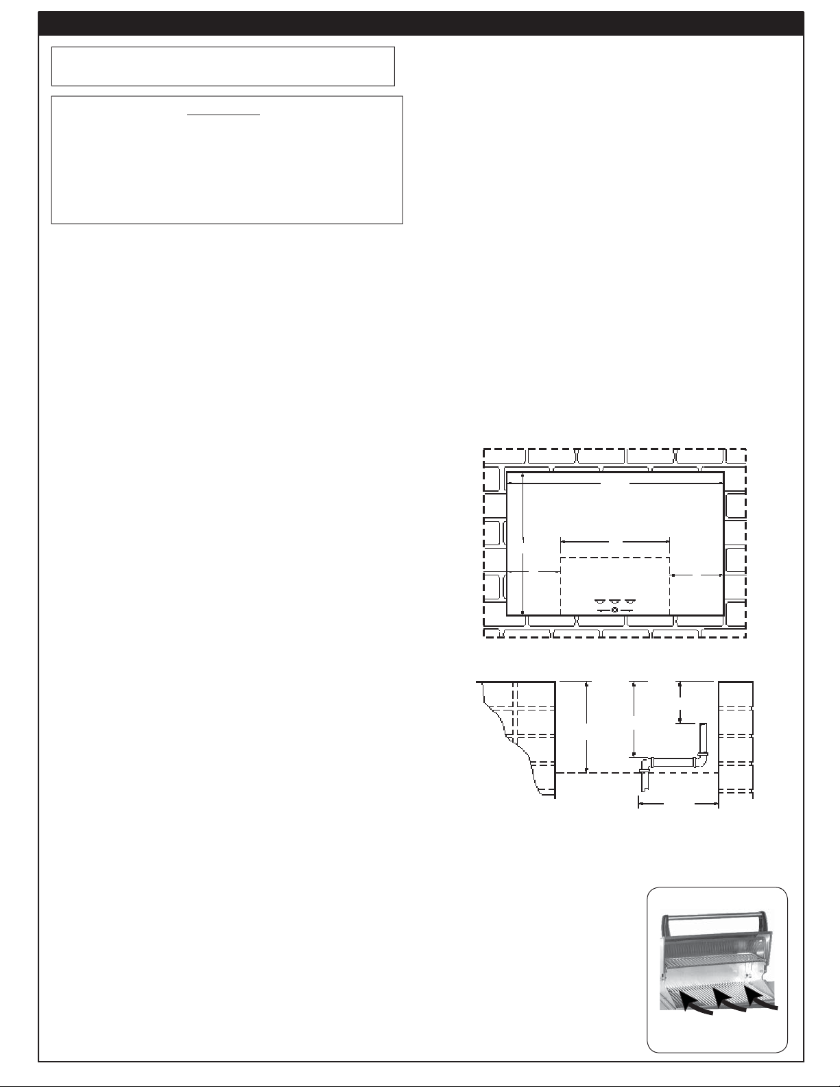
The pipe should terminate near the front and center
of the enclosure, no more than 5" (12.7 cm) from the
countertop. Installation will be simplifi ed if the pipe enters
the enclosure vertically from the bottom, at least 6" (15.2
cm) in from each side, and within 8" (20.3 cm) of the front
Fig. 4-1).
wall (
If the pipe does not come up against the front wall, it can
easily be run along the enclosure fl oor and turned up to
rise within 5" (12.7 cm) of the countertop, tight against the
front wall (leaving space only to connect fi ttings,
Fig. 4-2).
Note: An external valve in the gas line is necessary
for safety when the barbecue is not in use. It
also provides for convenient maintenance and
repair. A removable key is recommended.
GAS SUPPLY AND MANIFOLD PRESSURE:
For natural gas - Normal 7" (17.8 cm) w.c. (water
column), minimum 5" (12.7 cm), maximum 101/2" (26.7
cm).
For propane gas - Normal 11" (27.9 cm) w.c., minimum 8" (20.3
cm), maximum 13" (33 cm).
Top view
24 1/4'
Back
ENSURING PROPER COMBUSTION AIR AND
COOLING AIR FLOW
1
The
/2" (1.27 cm) vent space between the top panel of
the unit and the countertop that is created by the attached
cork mounting pads resting on the countertop must be left
clear. Blockage of barbecue air fl ow causes overheating
and poor combustion. A vent screen is provided to cover
this opening.
ELECTRICAL OUTLETS
Electrical outlets in the vicinity of the barbecue, which
might be used for rotisserie motors or other appliances,
must be properly grounded.
Note: Keep electrical supply cords away from all
heated surfaces.
EXHAUST REMOVAL
If installed under a patio roof, the cooking grid area must be
fully covered by a chimney and exhaust hood. An exhaust
fan with a rating of at least 1,000 CFM (472 liters per
second) or more may be necessary to effi ciently remove
smoke and other cooking by-products from the covered
area. Do not install in a fully enclosed area of any kind.
GAS SUPPLY PLUMBING REQUIREMENTS
1
1
Rigid
/2" (1.27 cm) black steel pipe is required to conduct
the gas supply into the barbecue enclosure for connection
to the unit. Pipe joint compound that is resistant to all
gasses should be applied to all male fi ttings and all joints
tightened securely. Do not use pipe joint compound to
connect fl are fi ttings.
REV 2 - 0809241402
Rear
19 1/4'
Stub out gas pipe anywhere in
6'
Vertical pipe up against front
Fig. 4-1 - Top view
Fig. 4-2 - View from left
12" Max
12'
this area
6'
Countertop
5" Max
9" Max
8" Max
CAUTION: Wind blowing into or across the rear oven lid vent
can cause poor performance and/or dangerous
overheating. Orient the grill so that the prevailing
wind blows toward the
front of the grill (Fig.
CORRECT
4-3).
CAUTION: To prevent dangerous
overheating, the rear
of the unit must have a
minimum clearance of
8” from any backsplash/
wall.
4
Place grill so prevailing wind
blows toward front of grill
Fig. 4-3
L-C2-01808
Front
Page 5
INSTALLATION
Perform the following checks before installing the barbecue:
CHECK BARBECUE FUEL ORIFICE SIZE
This barbecue comes from the factory confi gured for one
type of gas as marked on the label behind the barbecue
face plate. Each burner uses a different orifi ce depending
on the gas used in the barbecue. Please refer to Table 1 for
the correct orifi ce size.
1. Remove the cooking grids and fl avor grid from the
barbecue.
2. If the gas supply has been connected, make sure the
burner valve is in the OFF position. Then pull the knobs
from their stems. Use a Phillips screwdriver to turn the
face fastener screws counterclockwise to release the
face and remove it from the barbecue. Make sure to
retain the screws and fi nish washers until you are ready
to reattach the face.
Note: Carefully lift the face away from the frame. The
spark generators for the ignition system are
attached to the inside of the face panel. The spark
generator need not be detached, but the wires
must be unplugged from the generators before
the face is removed.
3. Using a fl at-blade screwdriver, pry the burner retaining
clip from rear wall of the barbecue frame (see
Remove the burner by: 1) Pulling it to the front of
the barbecue, 2) Lifting the far end out of the notch,
3) Pulling the burner away from the manifold, taking
care not to lose the air shutter and spring, which may
become detached when the burner is removed.
4. Using a 3/8" socket, remove orifi ce from the orifi ce holder
on the burner manifold and check the number stamped
on the face (see barbecue fuel orifi ce size in Table 1).
Repeat for each burner as necessary.
5. Replace the orifi ce with an orifi ce of the proper drill size as
listed in the PRODUCT DATA TABLE.
6. After checking the orifi ce drill size or replacing the orifi ce,
install the air shutter spring and the air shutter over the
orifi ce holder fi tting, between the burner and the burner
manifold, in the order and position shown in Fig. 5-1.
7. Replace the burners in the holding groove, ensuring that
the brass orifi ce and orifi ce holder fi ttings project deeply
into the burners. Replace the burner retaining clips.
WARNING: It is critical to the continued safe operation of
the burner that it be properly aligned with the
orifi ce, as indicated above.
Fig. 5-1).
WARNING: A rubber or plastic connector will rupture
or leak, resulting in an explosion or
serious injury if used inside the barbecue
enclosure.
1. Make sure that the gas supply is turned OFF. Then
connect the
1
/
" (1.27 cm) pipe adapter fi tting supplied
2
with the stainless steel fl ex connector to the gas
supply stub. Use pipe joint compound that is resistant
to all gasses or Tefl on tape on all male pipe fi ttings
and tighten securely. Do not use pipe joint compound
to connect brass fl are fi ttings.
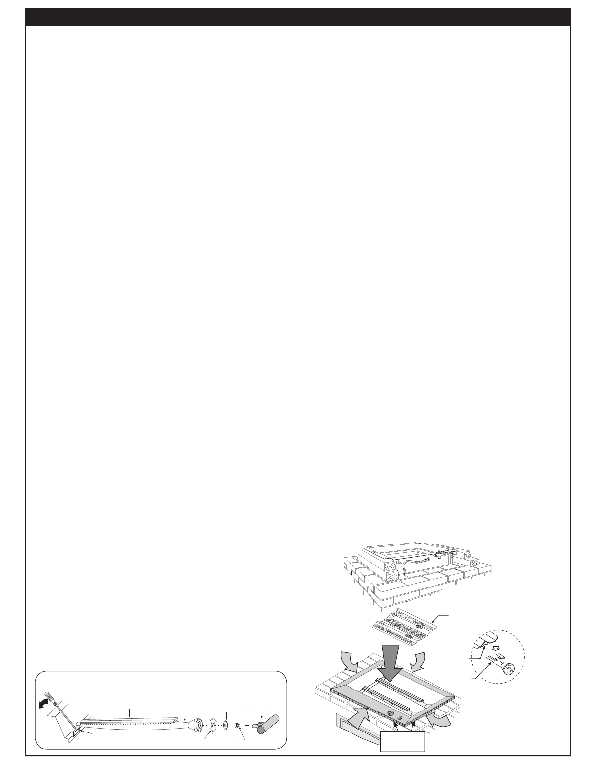
2. Lower the barbecue into place, making sure not to
pinch or kink the gas connector. The unit may be
supported above the counter by blocks inserted under
the fl anges at each side of the frame (Fig. 5-2).
3. If the pipe does not come up against the front wall, it
can easily be run along the enclosure fl oor and turned
up to rise within 5" (12.7 cm) of the countertop, tight
against the front wall (leaving space only to connect
fi ttings).
4. Connect the fl ex connector to the fl are fi tting on the
manifold inlet. Support the manifold inlet fi tting with
a wrench to avoid applying excessive torque to the
manifold assembly while tightening this connection
securely. Do not use pipe compound on fl are fi ttings.
Make sure the barbecue burner valve is in the OFF
position. Turn the gas supply on. Then carefully check all
gas connections for leaks with a brush and soapy water
before lighting. NEVER USE A MATCH OR OPEN FLAME
TO TEST FOR LEAKS.
5. Refer to the AIR SHUTTER ADJUSTMENT instructions
before replacing barbecue face and knobs.
INSTALL THE FLAVOR GRID
Place the fl avor grid directly on the burners (Fig. 5-3).
Center the grid over the burners with the open side up.
This allows heat from the burners to be evenly distributed
throughout the cooking area. The fl avor grid heats and cools
quickly, making your Fire Magic barbecue very responsive
to the changes you specify in grill temperature.
The fl avor grid is made of stainless steel and is rust
resistant. It may be cleaned with standard oven cleaners.
Fig. 5-2
CONNECT THE GAS SUPPLY TO BARBECUE
CAUTION: Use only stainless steel fl ex connectors that
are C.S.A. listed.
Fig. 5-1
BURNER
Burner manifold
MANIFOLD WITH
SPRING
Spring
with orifi ce holder
ORIFICE HOLDER
ORIFICE
Orifi ce
Burner clip
REV 2 - 0809241402
BURNER CLIP
Burner
BURNER
Burner neck
BURNER NECK
AIR SHUTTER
Air shutter
5
Ventilation
air
Ventilation
openings
Flavor grid
Flavor grid
leg
Burner
Important: Keep ventilation
openings clear.
Fig. 5-3
L-C2-01808
Page 6

U
L
SAFE USE & MAINTENANCE OF PROPANE-GAS CYLINDERS
IMPORTANT FOR YOUR SAFETY
READ AND FOLLOW ALL WARNINGS PROVIDED WITH THE PROPANE-GAS CYLINDER.
When operating this appliance with a propane-gas cylinder, these instructions and warnings MUST be observed.
FAILURE TO DO SO MAY RESULT IN A SERIOUS FIRE OR EXPLOSION.
CYLINDER/CONNECTOR REQUIREMENTS
a. Propane-gas cylinders, valves, and hoses must be
maintained in good condition and must be replaced if
there is visible damage to either the cylinder or valve. If the
hose is cut or shows excessive abrasion or wear, it must
be replaced before using the gas appliance (see e.).
b. This unit, when used with a cylinder, should be connected
to a standard 5-gallon (20 lb.) propane-gas cylinder
equipped with an OPD (Overfi ll Prevention Device).
The OPD has been required on all cylinders sold since
The use of pliers or a wrench should not be necessary. Only
cylinders marked “propane” may be used.
To disconnect: Turn the hand nut counterclockwise until
detached (Fig. 6-1).
Important: Before using the unit, and after each time the
cylinder is removed and reattached, check
the hose for wear (see a.) and check all
connections for leaks. Turn off the unit valves
and open the main cylinder valve, then check
connections with soapy water. Repair any
leaks before lighting the unit.
October 1,1998, to prevent overfi lling.
c. Cylinder dimensions should be approximately 12" (30.5
cm) in diameter and 18" (45.7 cm) high. Cylinders must
be constructed and marked in accordance with the
Specifi cations for Propane Gas Cylinders of the U.S.
Department of Transportation (D.O.T.) or the National
Standard of Canada, CAN/CSA-B339, Cylinders,
Spheres, and Tubes for Transportation of Dangerous
Goods.
d. The cylinder must include a collar to protect the cylinder
valve, and the cylinder supply system must be arranged
for vapor withdrawal.
e. The pressure regulator and hose assembly used must
e. The pressure regulator and hose assembly (Fig. 6-1)
match the specifi cation for Type I by ANSI Z 21.58-2005/
supplied with this outdoor-cooking gas appliance must
CGA 1.6-2005 (see Fig. 6-1).
be used. Original and replacement pressure regulator
and hose assemblies must be those specifi ed by the
manufacturer for connection with a cylinder connecting
device identifi ed as Type I by the ANSI Z 21.58-2005/CGA
1.6-2005 (see PARTS LIST for ordering information).
f. The propane-gas cylinder valve must be equipped with a
cylinder connection coupling device, described as Type
I in the standard defi ned in paragraph e. above. This
device is commonly described as an Acme thread quick
CAUTION: Always turn the propane cylinder main valve
off after each use, and before moving the unit
and cylinder or disconnecting the coupling.
This valve must remain closed and the
cylinder disconnected while the appliance
is not in use, even though the gas fl ow is
stopped by a safety feature when the coupler
is disconnected.
Carefully inspect the hose assembly each time before the
gas is turned on. A cracked or frayed hose should be replaced
immediately.
If the appliance is stored indoors, the cylinder must be
disconnected and removed.
Cylinders must be stored out of
doors, out of the reach of children, and must not be stored
in a building, garage, or any other enclosed area.
FOR YOUR SAFETY
a. DO NOT store a spare propane-gas cylinder under or
near this appliance.
b. NEVER fi ll the cylinder beyond 80-percent full.
c. IF THE INFORMATION IN a. AND b. IS NOT FOLLOWED
EXACTLY, A FIRE CAUSING DEATH OR SERIOUS
INJURY MAY OCCUR.
coupler.
g. If the propane-gas cylinder comes with a dust plug, place
the dust cap on the cylinder valve outlet whenever the
cylinder is not in use.
QUICK COUPLER OPERATION
To connect the regulator/hose assembly to the propanegas cylinder valve fi tting: Press the hand nut on the regulator
over the Acme thread fi tting on the cylinder valve. Turn the hand
Pressure
relief
valve
Fig. 6-1 Type I Acme thread quick coupler
QCC
Type 1
valve
Hand wheel
Brass Acme
thread fi tting
Liquid level
indicator
(optional)
Hand nut with Acme
thread
Regulator
Hose
nut clockwise to engage the threads and tighten until snug.
ENCLOSURE REQUIREMENTS
FOR YOUR SAFETY, you must provide the openings listed below for drainage, replacement air, and cross-ventilation
of any storage area exposed to possible leakage from gas connections, the unit, or propane cylinders:
One side of the gas cylinder enclosure left completely open to the outside OR by providing four (4) ventilation
openings. Two (2) openings are to be at the cylinder valve level (approx. 16" [40.6 cm] above the fl oor) and on
opposite walls of the enclosure. Two (2) more openings must be at the fl oor level on opposite sides of the enclosure.
The fl oor-level openings must start at the fl oor and shall extend no higher than 5" (12.7 cm) above the fl oor. Each
opening must have a minimum of 10 sq. in. (64.5 cm2) of free area. To achieve the proper ventilation, you may drill
a series of holes, omit the grout from masonry joints, or replace a brick with a hardware cloth screen. If the fl oor
in the cabinet is raised and the space beneath the cabinet is open to the outside, the lower ventilation openings
may be in the fl oor.
Consult your gas supplier for ventilation and regulator requirements when connecting to a household propane supply.
Vent
6
Page 7

CHECKING AND CONVERTING GAS TYPE
This unit comes from the factory confi gured for
one type of gas, as marked on the label behind the
faceplate.
Converting this unit to burn a different type of
gas requires a conversion kit from the factory.
The professional installer who converts this
unit to burn a different gas must perform the
following functions:
1. Change brass gas orifices (included at original
shipping) on each burner to match the new gas type
(see PRODUCT DATA TABLE, Table 1).
2. Switch the convertible gas regulator (included
at original shipping) to match the new gas type
(see below).
3. Plumb the unit to the new gas supply.
4. Apply a new label behind the faceplate, indicating
the new gas the unit will burn (included with
conversion kit).
WARNING
HAZARDOUS OVERHEATING WILL OCCUR
IF A NATURAL-GAS ORIFICE IS USED WITH
PROPANE GAS. IF YOU ARE NOT SURE IF THE
CORRECT ORIFICES ARE INSTALLED, OR IF AN
ORIFICE CHANGE IS NECESSARY, REFER TO
THE FOLLOWING INSTRUCTIONS.
CAUTION: Make sure the unit is at a safe
temperature and isolated from gas and
electrical supplies before beginning
the tasks outlined below.
Note: The cooler the unit, the greater the tolerances
between the stainless-steel parts, and
therefore the easier to disassemble and
reassemble parts of the unit.
CAUTION: For your safety, exercise caution and
use adequate hand protection (such
as gloves) when handling potentially
sharp sheet-metal parts.
Regulator: note the cap
on top
STEP 1:
Unscrew and remove the cap from the
regulator, extracting the converter.
CHECKING AND CONVERTING THE REGULATOR
Note: Each end of the plastic converter is engraved with either the letters “NAT”
or “L.P.” (propane) for the respective gasses. When the converter is in the
cap and the cap is held uppermost, the letters seen indicate the gas that
the regulator is set up for.
To convert the regulator from one gas to another, follow steps 1-4.
STEP 3:
Turn the converter around and
replace it carefully, into the
center of the cap (it will snap
Read gas
type here
STEP 2:
Remove the converter (the
plastic stalk) by carefully
pulling it away from the center
of the cap (it will snap out of
its seating).
into place). Check that you can
read the type of gas the unit is
set for.
STEP 4:
Replace the unit into the
regulator and screw down
until snug.
WARNING
THIS APPLIANCE REGULATOR IS RATED FOR 1/2 PSI MAXIMUM. IF YOUR GAS SUPPLY IS
GREATER THAN 1/2 PSI, AN ADDITIONAL REGULATOR MUST BE INSTALLED TO REDUCE
THE INPUT PRESSURE TO THE UNIT to 1/2 PSI OR LESS. SEE GAS-SUPPLY REQUIREMENTS
SECTION FOR PROPER GAS-SUPPLY PRESSURE.
7
Page 8

AIR SHUTTER ADJUSTMENT
Notch
MAIN BURNER AIR SHUTTER ADJUSTMENT
Important: The air shutters must be adjusted
after installation. If not, this appliance
may not light, heat evenly, or cook
properly.
Main burner air shutters are easily accessed by
Main burner air shutters are controlled by the two
removing the front panel (face). The air shutters are
wire levers at the far right side of the cooking grill
located at the front of the burners behind the face
(see PARTS LIST). The air shutter has a small dimple
(see PARTS LIST). The air shutter has a small dimple
(see Fig.
(see Fig.
the burner face. This prevents the air shutter from
the burner face. This prevents the air shutter from
moving.
moving.
1. Using the two, long air shutter levers, close
2. Light the barbecue in accordance with the
USE PROPERLY INSULATED TOOLS TO MAKE
THESE ADJUSTMENTS. NEVER TOUCH A
HOT BARBECUE DIRECTLY TO MAKE
8-1) that allows it to lock into notches in
8-1) that allows it to lock into notches in
the air shutters by turning the tabs to a vertical
position (Fig.
WARNING
8-2).
LIGHTING INSTRUCTIONS and burn for two
minutes with the knobs on HI LIGHT and the oven
open.
ADJUSTMENTS.
3. After burning for two minutes, open the air shutters,
1. Using the tip of a long screwdriver, close the air
using the air shutter levers, until the fl ames lift
shutters by turning the tabs to a vertical position
off, or appear not to be touching the burners (Fig.
(Fig.
8-2).
8-1).
2. Light the barbecue in accordance with the
4. Begin closing the air shutters, with the air shutter
LIGHTING INSTRUCTIONS and burn for two
levers, until the flames appear to burn while
minutes with the knobs on HI LIGHT and the
touching the burner ports (Fig.
8-2).
oven open.
Note: You may then see short yellow tips on the
3. After burning for two minutes, open the air
Note: Barbecues, in some installations, achieve
4. Begin closing the air shutters, with the tip of a
fl ames. If fl ames are a lazy yellow, open the
shutters, using the tip of a screwdriver, until
air shutters until the fl ame is blue with yellow
the fl ames lift off, or appear not to be touching
tipping.
the burners (Fig.
a better air/gas mixture and will ignite more
screwdriver, until the fl ames appear to burn while
quickly if the valve is fi rst turned beyond HI
touching the burner ports (Fig.
8-1).
8-2).
LIGHT to LOW for lighting.
Note: You may then see short yellow tips on the
fl ames. If fl ames are a lazy yellow, open the
air shutters until the fl ame is blue with yellow
tipping.
Partially open
Fig. 8-1
(Turn tabs)
Closed
Fig. 8-2
Fig. 8-1 & Fig. 8-2 - Air shutter adjustment diagram
Ta b
Dimple
Flame off ports
Flame on ports
Note: Barbecues, in some installations, achieve a
better air/gas mixture and will ignite more
quickly if the valve is fi rst turned beyond HI
LIGHT to LOW for lighting.
8
Page 9

BARBECUE SAFETY INFORMATION & MAINTENANCE
Each time you use the barbecue, make sure that:
1. The area around the barbecue is clear of fl ammable
vapors, liquids, and substances such as gasoline,
yard debris, wood, etc.
2. There is no blockage of the airfl ow through the vent
space located below the face of the unit.
3. When using propane gas:
a. The special ventilation openings in the enclosure
should be kept free and clear of debris
(see PLANNING THE LOCATION OF THE
BARBECUE).
b. If connected to a propane cylinder, the rubber
hose attached to the regulator should be carefully
inspected before each use.
c. The propane cylinder, regulator, and rubber hose should
be installed in a location not subject to heating above
125° F (51° C).
4. The burner fl ames burn evenly along both sides of
each burner with a steady fl ame, which is mostly
blue with yellow tipping. (Refer to section on AIR
SHUTTER ADJUSTMENT.) If burner fl ames are not
normal, check the orifi ce and burner for insects or
insect nests.
5. The inline gas valve or gas cylinder valve is always
shut OFF when the barbecue is not in use.
DRIP COLLECTION SYSTEM
The drip collector in this barbecue is part of the unit’s
main frame and is located below the burners. The drip
collector has one hole that will allow excess drippings to
fall through during cooking, while separating the fi rebox
from the drip tray. Clean the drip tray after each use.
The drip collector allows you to brush or scrape residue
from the barbecue’s inner liner into the drip tray.
Following the manufacturers instructions and regular
cleaning of the barbecue’s interior with oven cleaner,
will help to prevent grease fi res.
Periodically check the burners to make sure they
are clear of debris. Properly adjusted burner fl ames
burn evenly along both sides of each burner with
a steady fl ame (mostly blue with yellow tipping). If
burner fl ames are not normal, check the orifi ce and
burner for insects or insect nests. (See section on
CHECKING/CONVERTING THE BURNER ORIFICES
for instructions on burner removal and replacement.)
Check the burner ports at least annually for blockage by
removing the burner (see orifi ce changing instructions)
and visually inspect the gas intake tube for insects
and nests. A clogged tube can lead to a fi re beneath
the grill.
6. The drip collector hole is clear and unobstructed.
Excessive grease deposits can result in a grease
fi re.
7. The barbecue is free and clear from combustible
materials, gasoline, and other fl ammable vapors
and liquids.
WARNING
NEVER cover the entire cooking or grill surface with griddles or pans. Overheating will occur and
burners will not perform properly when combustion heat is trapped below the cooking surface.
CAUTION: NEVER spray water on a hot gas unit.
9
Page 10

Read entire instructions before lighting, and follow these instructions each time you light the grill.
ELECTRONIC LIGHTING
LIGHTING (IGNITION) INSTRUCTIONS
MANUAL LIGHTING
1. Open all lids and remove all covers from the burners
you wish to light.
2. Turn all gas control knobs to their OFF positions.
3. Turn on the gas at its source.
Note: No matter which lighting method you use,
DO NOT turn
on the gas to
more than one
burner at a time.
Adjacent grill
burners will
cross-ignite, and
TURN OFF
TO
TO TURN OFF
Read setting
Read setting
here
here
OFF
TO TURN ON
T O TURN ON
LIGHT
HI
High to
HIGH to
light
LIGHT
gas flow may
LOW
Fig. 10-1 - Valve control knob
be restricted.
CAUTION: If the burners do not light within five
seconds, depress the control knob
and turn the knob to OFF. WAIT FIVE
MINUTES before repeating step 4. If you
smell gas, follow the instructions on the
cover of this manual. If the burners still do
not light after several attempts, refer to the
instructions for MANUAL LIGHTING.
4. Depress the control knob for the burner to be lit
and turn it to the HI LIGHT position, then press the
ignition button. Once the burner lights, release the
ignition button.
5. Repeat step 4 for each additional burner to be lit.
CAUTION: Always wait fi ve minutes for gas to clear
after any unsuccessful lighting attempt.
1. Follow steps 1 through 4 (left).
2. Insert either a burning long-barrel butane lighter,
a burning long-stem match, or a burning match
held by a wire extension holder (Fig. 10-2) through
the cooking grids to the burner (Fig. 10-3).
For backburners, hold the flame against the
perforated material of the backburner.
For sideburners, hold the fl ame against the burner.
3. While holding the match or lighter fl ame next to
the burner, depress the appropriate burner control
knob and turn it counterclockwise to the HI LIGHT
position. When the burner lights, remove the lighter
or match.
Fig. 10-2 - Match holder
4. If the burner does not light, IMMEDIATELY depress the
knob and turn the burner control knob to OFF. WAIT
FIVE MINUTES before repeating steps 2 through 4
of the MANUAL LIGHTING INSTRUCTIONS.
Note: Some installations achieve a better air/gas
mixture and may ignite quicker if the burner
control knob is fi rst turned beyond HI LIGHT
to LOW for lighting.
FOR PROPANE ONLY
Propane tanks are equipped with a safety shutdown
device that may cause low or no gas pressure/fl ame
at the burners if operating and lighting instructions
are not followed exactly (See important note in the
TROUBLESHOOTING section for more details.)
Fig. 10-3 - Manual lighting
REMEMBER: FOR SAFE MANUAL LIGHTING, PLACE A
BURNING MATCH OR BUTANE LIGHTER BESIDE THE
BURNER - THEN TURN ON THE GAS (see Fig. 10-3).
SHUTTING OFF THE GRILL
To shut off the grill, push in each valve control knob and
turn it clockwise to the OFF position.
Always close the valve to the gas supply after each use
of the grill.
10
Page 11

REPLACING THE IGNITOR BATTERY
1. Remove the ignitor cover by turning it counterclockwise.
Important: Do not
attempt to pull or
turn the rubber cap.
WRONG!!
2. Remove battery for
replacement. The battery
is reinstalled with the
negative (-) end out.
3. After properly inserting the
battery, replace the ignitor cover
by turning the cap clockwise.
Note: If you have accidentally removed the rubber cap,
follow the instructions below to replace it.
1. Pull the rubber
cap and the inner
plastic sleeve
apart.
2. Carefully insert
the rubber cap into
the ignitor cover so
it sits behind inner
lip.
3. Turn the cap
over and slide the
inner plastic sleeve
into the cap.
TROUBLESHOOTING
If you have trouble with the gas grill, please use this list to identify the problem. By trying one or more of
the solutions to the possible cause, you should be able to solve the problem. If this list does not cover your
present problem, or if you have other technical diffi culties with the grill, please contact your local dealer.
PROBLEM POSSIBLE CAUSE CORRECTION
1) Improper air shutter
1) Adjust air shutters.
adjustment
Ignition system failure
2) Ignition wire disconnected 2) Replug wires into generator.
3) Low gas pressure 3) Adjust or replace battery.
4) Dead battery 4) Replace battery.
5) Improper air shutter
5) Adjust air shutters.
adjustment
6) Using propane orifi ce for
6) Change orifi ces.
natural gas
Insuffi cient heat
7) Low gas pressure/fl ame
(natural)
8) Low gas pressure/fl ame
(propane)
7) Have gas company check the
operating pressure at the grill.
8) Refi ll propane tank, or reset
propane tank safety*: Shut off
all valves (including propane
tank) and follow lighting
instructions exactly.
Uneven heating
9) Burner ports partially blocked
by debris
10) Small spiders or insects in
burner
9) Remove burners and clean out
ports.
10) Inspect burners for spider
webs or other debris that may
block gas fl ow.
Rotisserie noisy
Note: *Propane tanks are equipped with a safety shutdown device that may cause low or no gas/fl ame at the
burners if operating and lighting instructions are not followed exactly. If you suspect the propane tank
safety shutoff is in effect, shut off all burner control valves and the propane tank valve. Then read and
follow the LIGHTING INSTRUCTIONS exactly. Lighting instructions are located in the owner’s manual
and printed on the grill’s metal drip tray. If the problem persists, continue troubleshooting, or contact
your local dealer or distributor for assistance.
11) Rotisserie out of balance 11) Adjust counterbalance.
11
Page 12

ACCESSORIES
THE GRILL BRUSH (OPTIONAL)
Purchase a Fire Magic® stainless-steel grill brush (sold
separately) to keep your grill cleaner. It comes with
scraper for large particles and a replaceable head with
brass bristles for
overall cleaning.
Fig. 12-1
Grill brush with replacement head
THE COOKING GRID LIFTER
Hold the grid lifter by gripping the center section with the
prongs pointing down (use an oven mitt or heavy glove
if the grill is hot). Insert the notched end of the grid lifter
into the cooking grid, in front of the midway point (front to
back; Fig. 12-3), and central (left to right; Fig. 12-4).
Twist the grill lifter (clockwise or counterclockwise) so
the handle is parallel to the grill rods. This “seats” the
spiked end of the grid lifter between two rods, enabling
you to safely lift out the grid. Lift slowly and adjust the
grid lifter, if necessary, for balance.
THE DRIP PAN
THE WARMING RACK
The warming rack (Fig. 12-2) is packed separately.
To install the warming rack, lift the front of the rack
up slightly and insert the rack hangers into the two
holes in the back of the inner oven hood just above the
backburner. Then lower the front of the rack into a level
position to lock the rack in place.
To remove the warming rack, lift up on the front of the
rack until the rack hangers pull free from their supporting
holes.
Note: Removing the warming rack before using the
rotisserie will leave more clearance for the
meat being cooked.
Fig. 12-2 Warming rack in place inside oven
The drip collection system allows you to brush or scrape
excess dried residue from the grilling area directly into
the drip pan (see PARTS LIST for drip pan location).
To simplify cleanup when using the rotisserie, you may
place a baking pan or foil under the rotisserie on top of
the burners to collect the drippings. Clean the drip pan
after each use.
THE FLAVOR GRID(S)
Place each fl avor grid directly over a burner or burner
pair. Center each grid over the burner, oriented as
shown in Fig. 12-5.
Note: This allows heat from the burners to be evenly
distributed throughout the cooking area. The
fl avor grids heat and cool quickly, making the
grill very responsive to changes in heat from
the burners.
Fig. 12-3
Placement of the grid lifter in cooking grid
Fig. 12-4
Fig. 12-5
12
Page 13

CARE & CLEANING
CARE AND CLEANING
Your new Fire Magic® grill represents the latest
and most advanced technology available. In order
to continue to enjoy the benefi ts of your grill and
to protect your investment, we recommend the
following:
Cover your grill with a Fire Magic
®
cover when not
in use (see section below).
Clean it with Fire Magic® stainless-steel grill cleaner
at least once a month (see Fig. 13-1).
Note: Due to the nature of stainless steel,
surface iron oxide deposits may appear.
Do not be alarmed – these deposits are
removable with stainless-steel cleaner
through periodic maintenance.
BE SURE THE GRILL IS OFF AND COOL
BEFORE CLEANING.
COVER
Check and clean the burner ports and carry-over
slits for blockage at least annually by removing
the burner (see orifi ce changing instructions) and
visually inspecting the burner inlet for insects and
nests. A clogged burner can lead to a fi re beneath
the grill.
The inside of the grill may be cleaned periodically
with oven cleaner if desired. Follow the oven cleaner
instructions for proper use.
By following these
recommendations,
you will enjoy the
Wipe with grain
beauty and power
of your grill for many
years to come.
Fig. 13-1 - Wipe with grain
PROTECTING YOUR GRILL
An optional heavy-duty cover will protect your grill’s
fi nish and preserve your investment. The waterrepellent material will protect your grill from the
weather.
Make sure to give the model number of your grill
when ordering a cover.
Important: Allow your grill to cool before
covering.
Important: Always close the gas-supply
shutoff valve to the grill.
If storing the grill for a long period
of time, disconnect the grill from the
gas supply completely.
Always check the burners before using the grill if
it has been unused over a long period. Look for
obstructions that may hamper performance and
safe operation of your grill.
Fig. 13-2
13
Page 14

FIRE MAGIC® OUTDOOR GAS GRILL LIMITED WARRANTY
PLEASE COMPLETE AND RETURN YOUR REGISTRATION CARD, WHICH IS INCLUDED WITH YOUR FIRE MAGIC® GRILL
LIFETIME WARRANTY - Fire Magic® cast stainless-steel burners, stainless-steel rod cooking grids, and stainless-steel housings are
warranted for as long as you own your Fire Magic® grill.
FIFTEEN-YEAR WARRANTY - Fire Magic® cast brass burners, brass valves, backburner assemblies (except ignition parts), and
manifold assemblies are warranted for 15 years from the date of purchase of your Fire Magic
THREE-YEAR WARRANTY - Fire Magic® sideburners and all other Fire Magic® grill components (except ignition and electronic
parts) are warranted for three (3) years from the date of purchase of your Fire Magic® grill.
Fire Magic® ignition systems (excluding batteries), electronic components (including lights and thermometers), and accessories are
warranted for one (1) year from date of purchase.
PLEASE KEEP A COPY OF YOUR SALES SLIP FOR PROOF OF PURCHASE
This warranty applies to the original purchaser and to single family residential use only. It commences from date of purchase, and is valid only with
proof of purchase.
This warranty does not cover parts becoming defective through misuse, accidental damage, electrical damage, improper handling, storage, and/or
installation. Product must be installed (and gas must be connected) as specifi ed in the instructions or operator’s manual, by a qualifi ed professional
installer. Accessories, parts, valves, remotes, etc., when used must be Peterson Co. product.
This warranty does not apply to rust, corrosion, oxidation, or discoloration, unless the affected component becomes inoperable. It does not cover
labor or labor-related charges.
This warranty specifi cally excludes liability for indirect, incidental, or consequential damages. Some states do not allow the exclusion or limitation of
incidental or consequential damages, so the above exclusion may not apply to you. This warranty gives you specifi ed legal rights, and you may have
other rights that may vary from state to state.
For additional information regarding this warranty, or to place a warranty claim, contact the R.H. Peterson dealer where the product was purchased.
®
grill.
ROBERT H. PETERSON CO.
Quality Check Date:___________
Orifi ce # (Main):__________
Orifi ce # (Other):__________ Model #: ___________
Leak Test: ___________ Serial #: ___________
Burn Test: ___________ Air Shutter: ___________
Gas Type: NAT. / PROPANE Inspector: ___________
Robert H. Peterson Co. • 14724 East Proctor Avenue • City of Industry, CA 91746Robert H. Peterson Co. • 14724 East Proctor Avenue • City of Industry, CA 91746
14
 Loading...