

FireMagic CUSTOM IN-GROUND POST CHARCOAL GRILL Installation And Operating Instructions Manual
Page 1

CUSTOM IN-GROUND POST
CHARCOAL GRILL
INSTALLATION AND OPERATING
INSTRUCTIONS
INSTALLER: Leave these instructions with consumer.
CONSUMER: Retain for future reference.
IMPORTANT: READ THESE INSTRUCTIONS CAREFULLY BEFORE STARTING INSTALLATION OR USE.
SAFETY WARNINGS & CODES
WARNING
1. Do not store or use gasoline or other
fl ammable vapors and liquids, including
propane cylinders, in the vicinity of this
or any other appliance.
CODE REQUIREMENTS: This grill must be installed in accordance with local codes and ordinances.
WARNING:
All surfaces of the charcoal unit become HOT during use. Exercise caution when using
this unit, especially when adding charcoal or cranking the charcoal pan up or down.
Improper installation, adjustment, alteration,
service, or maintenance can cause injury
or property damage. Refer to this manual.
For assistance or additional information,
consult a qualifi ed professional installer,
WARNING
or service agency.
TABLE OF CONTENTS
SAFETY WARNINGS & CODES 1
PARTS LIST 2
PLANNING THE LOCATION OF YOUR POST GRILL 2
EXHAUST REMOVAL 2
INSTALLATION AND SETUP 3
INSTALLATION 3
ATTACHING THE IN-GROUND POST EXTENSION 3
IN-GROUND PROCEDURE 3
ASSEMBLY 3
RIGID SHELF ASSEMBLY 4
OPERATION 4
USING YOUR CHARCOAL GRILL 4
ACCESSORIES 5
WARMING RACK 5
AIR SHUTTERS 5
CHARCOAL PROTECTOR 5
DRIP TRAY SPACER 5
CLEANING 5
USING THE GRILL BRUSH 5
USING THE COOKING GRID LIFTER 5
FIRE MAGIC
REV 2 - 0711071144
®
STAINLESS-STEEL CHARCOAL GRILL LIMITED WARRANTY 6
Robert H. Peterson Co. • 14724 East Proctor Avenue • City of Industry, CA 91746
1
L-C2-22807
Page 2
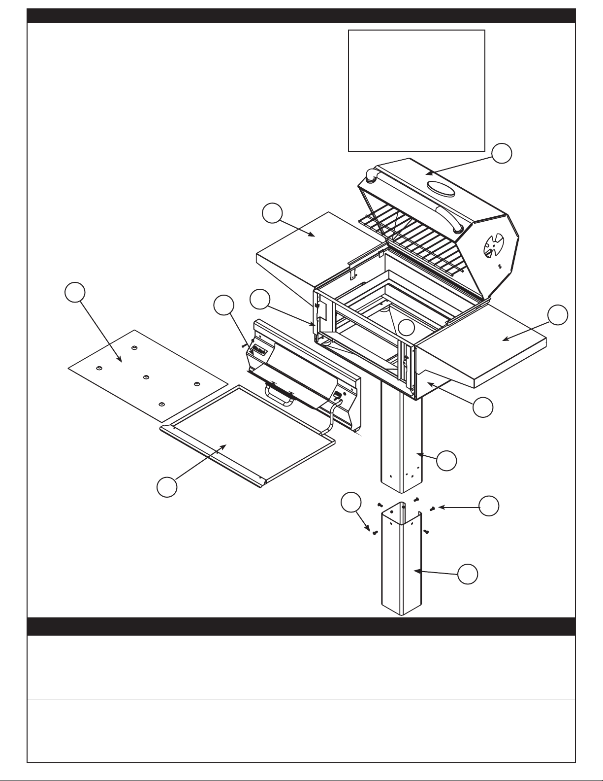
PARTS LIST
Item Description
1. Custom, smoking oven Lift-A-Fire (LAF)
2. Shelf, rigid (2)
3. Frame, charcoal Custom portable
4. Face, Custom LAF assembly
5. Drip tray, plate Custom
6. Custom, drip tray LAF assembly
7. Custom, pedestal base
8. In-ground post, charcoal (weld) assembly
9. In-ground post, extension (weld) assembly
1
10. Screw,
11. Plate, pan Custom LAF
/4-20 x .625 trss ph
Replacement parts can be ordered
from your local Fire Magic
®
dealer.
5
4
IMPORTANT
This Fire Magic® grill is
pre-assembled and tested at
the factory.
The plastic straps that
secure the oven to the grill
unit must be removed and
discarded prior to lighting.
1
2
7
2
11
3
8
6
10
Fig. 2-1
10
9
PLANNING THE LOCATION OF YOUR POST GRILL
This grill is designed FOR OUTDOOR USE ONLY.
DO NOT use this unit under unprotected fl ammable surfaces. DO NOT use this appliance inside a building, garage,
or any other enclosed area. It must not be used in or on recreational vehicles or boats.
Important: This unit is NOT insulated; therefore, during use it must be located with a minimum of 18" of side
and back clearance from unprotected combustible materials, such as wood, plastic, or stucco with
wood framing.
EXHAUST REMOVAL
If installed or used under a patio roof, the cooking grid area should be fully covered by a chimney and exhaust
hood. An exhaust fan with a rating of 1,000 CFM (cubic feet per minute) or more may be necessary to effi ciently
remove smoke and other cooking by-products from the covered area. THIS UNIT SHOULD NOT BE LOCATED
IN A FULLY ENCLOSED AREA OF ANY KIND.
REV 2 - 0711071144
2
L-C2-22807
Page 3

INSTALLATION AND SETUP
ALIGN CRANK HANDLE
WITH NUT & SCREW IN
INSTALLATION
CAUTION: Metal edges are sharp. Use adequate
hand protection, such as gloves,
when assembling and confi guring
the grill.
ATTACHING THE IN-GROUND POST
EXTENSION
1. Attach the extension to the bottom of the grill
post so that the open portion is toward the back
of the grill and the fi ve (5) holes in the extension
line up with the fi ve (5) weld-nuts in the post.
2. From outside the joined
post and extension,
insert one of the
20-5/8" bolts (supplied)
1
/4 x
To grill
Weld-nut
into each of the fi ve (5)
bolt holes and tighten
each using a 7/16" socket
driver or wrench (see
Fig. 3-1).
Bolts
Fig. 3-1
Note: There is one (1) hole on each side of the
post, except the back, which has two
(2) holes located on either side of the
extension opening.
IN-GROUND PROCEDURE
Read instructions
carefully all the way
through before beginning
the installation.
Fig. 3-2
Post
(back view)
1. Dig a hole for the
post and extension
approximately 18"
Ground level
deep and 10-12" in
diameter.
Concrete level
Note: The actual depth
of the hole should
be such that the
cooking surface is
36" above ground
level.
3. While the concrete is still wet, carefully lower
the grill post and attached extension into the
hole.
4. Orient the grill per plan, then level the grill and
support it so that it remains in position while the
concrete dries.
ASSEMBLY
Carefully unpack your grill and check the parts.
1. Locate the crank handle (Fig. 3-3) packed
inside the grill enclosure.
2. Open the door in the front panel as shown in Fig.
3-3. Insert the threaded end into the crank
handle through the hole on the right of the grill
face and into the nut on the frame as shown.
3. Center the crank on the nut and begin cranking
in a clockwise direction until the threads have
properly caught hold.
4. Close the door in the front panel and continue
cranking until the lifter begins to move upward
inside the grill.
Note: The access door must be closed for the
crank to raise the lifter to the highest
position.
5. Place both cooking grids with cut-outs toward
the front, as shown in Fig. 3-4.
6. Install both
shelves as
Align crank handle with
nut and screw in
Crank
indicated on
the following
page.
Door
Fig. 3-3
Fig. 3-4
2. Pour the concrete into the hole approximately
3-5" below ground level.
REV 2 - 0711071144
3
L-C2-22807
Page 4

RIGID SHELF ASSEMBLY
This grill comes with two (2) rigid shelves that must
be attached. These can be attached using the four
(4) support screws provided and a long Phillips-head
screwdriver.
1. Hold the shelf inverted so that one of the corner
holes in the shelf lines up with the appropriate
upper screw hole in the grill.
2. Insert the screw (but do not tighten all the way)
so that the shelf can be easily rotated around
the fi rst screw.
3. Line up the second corner hole in the shelf with
the remaining upper screw hole in the grill. Insert
a screw and tighten.
Note: You may lift the edge of the shelf upward
to gain better access during much of the
tightening of this screw.
4. Finally, insert the bottom screws on the left and
right side of the shelf and securely tighten all
screws.
Detaching is the reverse process of above.
Shelf support screws
View from under right shelf
Fig. 4-3
OPERATION
Simple to use, this elegant stainless-steel charcoal
grill has the added benefi t of an adjustable charcoal
pan to allow you to change the height of the charcoal
while cooking, and gives you the ability to add fuel
without having to remove the cooking grids. This
enables the outdoor chef to be in complete control
of the cooking heat at the grilling surface.
USING YOUR CHARCOAL GRILL
1. Remove the cooking grids and pile your charcoal
on the charcoal pan(s). Avoid spillage.
2. Follow the instructions supplied with your
charcoal/fuel for lighting.
3. Use the access door to add or spread out your
coals while cooking.
CAUTION: Use long-handled insulated barbecuing
tools to prevent burns from hot metal
or coals.
4. Turning the crank handle raises or lowers the
pan to increase or decrease the grilling heat as
you desire.
REV 2 - 0711071144
4
L-C2-22807
Page 5

ACCESSORIES
WARMING RACK
The warming rack (See Fig. 2-1) is pre-assembled at
the factory and is useful in keeping food warm during
or after cooking.
Note: Please take into consideration that the warming
rack moves closer to the grill when the oven lid is
closed.
AIR SHUTTERS
Fig. 5-1
USING THE GRILL BRUSH
Purchase a Fire Magic® stainless-steel grill brush to
keep your grid top clean. Complete with scraper for large
particles and replaceable head with brass bristles for
overall cleaning.
CAUTION: The air shutters become
very hot when the grill
is in use. Use a tool or
heat-insulated glove to adjust the air
shutters.
The air shutters (Fig. 5-1) on both sides of the oven
can be used to regulate the fl ow of air to the coals when
the oven is closed.
Fig. 5-2
CHARCOAL PROTECTOR
The charcoal protector allows meat
drippings to drip down to the drip tray
without affecting the charcoal.
Place it over the coals as shown in Fig. 5-2.
DRIP TRAY SPACER
The drip tray spacer (see Parts List, item No. 5) sits on
top of the drip tray with the charcoal on top of it. It creates
an air space to prevent the drip tray from overheating.
Fig. 5-3
Grill brush with replacement head
USING THE COOKING GRID LIFTER
Hold the grid lifter by gripping the center section with the
prongs pointing down (use an oven mitt or heavy glove
if the grill is hot). Insert the notched end of the grid lifter
into the cooking grid, in front of the midway point (front
to back; Fig. 5-4), and central (left to right; Fig. 5-
5). Twist the grid lifter (clockwise or counterclockwise)
so the handle is parallel to the grid rods. This “seats” the
spiked end of the grid lifter between two rods, enabling
you to safely lift the grid out of the grill. Lift slowly and
adjust the grid lifter, if necessary, to balance.
CLEANING
CARE AND CLEANING
Your new Fire Magic® grill represents the latest
and most advanced technology available. In order
to continue to enjoy the benefi ts of this technology
and to protect your investment, we recommend the
following.
Cover your grill with a Fire Magic® cover when not
in use.
Clean the unit with a quality stainless-steel cleaner
at least once a month (see Fig. 5-6). For
thorough cleaning, the oven handle assembly may
be removed (see Fig. 5-7).
Note: In a humid environment,
due to the nature of
stainless steel, iron oxide
REV 2 - 0711071144
Fig. 5-7
Fig. 5-4
Placement of the grid lifter in cooking grid
Fig. 5-5
deposits may appear. Do not be alarmed
– these deposits are removable with
stainless steel cleaner during periodic
maintenance.
The inside of your grill, especially the removable drip
tray, may be cleaned periodically with oven cleaner
if desired. Follow the oven cleaner instructions for
proper use.
By following these
recommendations,
Wipe with grain
you will enjoy the
beauty and power
of your Fire Magic®
grill for many years
to come.
5
Fig. 5-6 - Wipe with grain
L-C2-22807
Page 6

FIRE MAGIC® STAINLESS-STEEL CHARCOAL GRILL LIMITED WARRANTY
FIVE-YEAR WARRANTY - Fire Magic® stainless steel charcoal grills (excluding the charcoal pan and ash tray) are warranted for fi ve
(5) years from the date of purchase of your Fire Magic
ONE-YEAR WARRANTY - Fire Magic
your Fire Magic® charcoal grill.
PLEASE KEEP A COPY OF YOUR SALES SLIP FOR PROOF OF PURCHASE
This warranty applies to the original purchaser and to single family residential use only. It commences from date of purchase, and is valid only with
proof of purchase.
This warranty does not cover parts becoming defective through misuse, accidental damage, electrical damage, improper handling, storage, and/or
installation. Product must be installed (and gas must be connected) as specifi ed in the instructions or operator’s manual, by a qualifi ed professional
installer. Accessories, parts, valves, remotes, etc., when used must be Peterson Co. product.
This warranty does not apply to rust, corrosion, oxidation, or discoloration, unless the affected component becomes inoperable. It does not cover
labor or labor-related charges.
This warranty specifi cally excludes liability for indirect, incidental, or consequential damages. Some states do not allow the exclusion or limitation of
incidental or consequential damages, so the above exclusion may not apply to you. This warranty gives you specifi ed legal rights, and you may have
other rights that may vary from state to state.
For additional information regarding this warranty, or to place a warranty claim, contact the R.H. Peterson dealer where the product was purchased.
®
charcoal pan and ash trays are each warranted for one (1) year from the date of purchase of
®
charcoal grill.
ROBERT H. PETERSON CO.
Quality Check Date:___________
Orifi ce # (Main):__________
Orifi ce # (Other):__________ Model #: ___________
Model #: ___________ Serial #: ___________
Leak Test: ___________ Serial #: ___________
Inspector: ___________
Burn Test: ___________ Air Shutter: ___________
Gas Type: NAT. / PROPANE Inspector: ___________
Robert H. Peterson Co. • 14724 East Proctor Avenue • City of Industry, CA 91746
6
 Loading...