

Page 1
GETTING STARTED
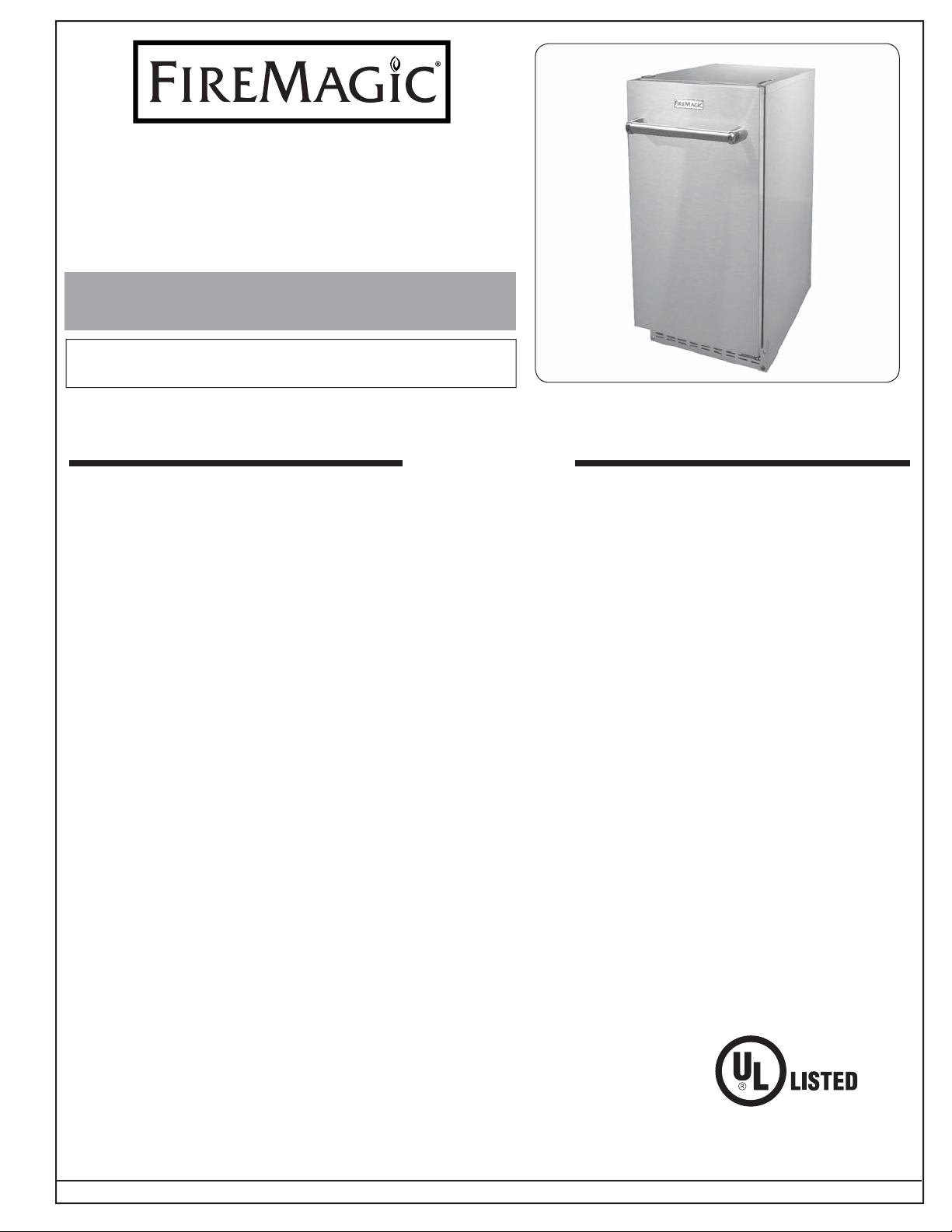
AUTOMATIC OUTDOOR
INSTALLATION INSTRUCTIONS
AND OWNER’S MANUAL
INSTALLER: Leave these instructions with consumer.
CONSUMER: Retain for future reference.
Important: READ THESE INSTRUCTIONS CAREFULLY BEFORE STARTING INSTALLATION OR USE.
KEEP THIS MANUAL IN A SAFE PLACE AFTER READING IT.
ICE MAKER
Model # 3597
WARNINGS
Do not use where the supply voltage is different from the unit's requirements.
This product is designed for indoor/outdoor use.
The appearance, design, color, and parts of the product are subject to change without notice.
The functions and specifi cations stated in this manual may be changed at anytime without prior notice.
The manual has WARNING and CAUTION marks. The information is impor tant for the safe and effi cient installation
and operation of the ice maker. Two types of cases may be found during installation:
CAUTION: If the instructions are not observed, a situation that may result in minor injury and/or damage to
the product may occur.
WARNING: If the instructions are not observed, serious injury or death may result.
Thank you for purchasing the 3597 Ice Maker (drain pump is optional). The product is a built-in and free-standing
type of ice maker and is designed for use at home. The product produces transparent ice of the highest quality.
Proper installation of the ice maker is of the utmost importance. The product should be installed by a qualifi ed
professional service technician.
Before installing the product, read this installation manual in full. The manual contains detailed instructions to
be observed during installation. If you have any questions about installation, contact your dealer.
Important: When designing or manufacturing the ice maker, safety matters and functions are accorded the
utmost importance. This ice maker is designed and certifi ed according to the UL safety standard.
The company does not bear any responsibility or liability for products that are modifi ed, installed
with parts not supplied or approved, or used incorrectly. R.H. Peterson reserves the right to change
product specifi cations and design at any time without prior notice.
REV 0 - 1608220820
SA32944
Robert H. Peterson Co. • 14724 East Proctor Avenue • City of Industry, CA 91746
1
L-C2-499
Page 2

CONTENTS
GETTING STARTED
WARNINGS .................................................................................................................................................. 1
IMPORTANT INFORMATION
UNPACKING ...........................................................................................................................................3
VENTILATION ........................................................................................................................................3
WATER SUPPLY .....................................................................................................................................3
WATER QUALITY ...................................................................................................................................3
INTERIOR OF UNIT ...............................................................................................................................3
ELECTRICAL SAFETY INFORMATION ..............................................................................................4
SPECIFICA TIONS AND DIMENSIONS ................................................................................................4
PARTS LIST ..................................................................................................................................................7
ITEM CHECK LIST ....................................................................................................................................8
INSTALLATION
INSTALLATION ..........................................................................................................................................9
INSTALL ICE MAKER ............................................................................................................................9
DOOR REVERSAL (if applicable) ........................................................................................................10
.................................................................................................................3
USE, CARE, & SERVICE
OPERATION ...............................................................................................................................................11
INITIAL OPERATION ...........................................................................................................................11
USING THE ICE MAKER .....................................................................................................................11
ICE ........................................................................................................................................................11
ICE CONTAINER ..................................................................................................................................11
OPERATION TIME ...............................................................................................................................11
ICE PRODUCTION ..............................................................................................................................11
SER VICING AND CLEANING ..............................................................................................................12
EXTERIOR ............................................................................................................................................12
ICE CONTAINER ..................................................................................................................................12
CONDENSER ........................................................................................................................................12
ICE REMOVAL CYCLE ........................................................................................................................12
HOW IT MAKES ICE ............................................................................................................................12
ICE-PRODUCTION SYSTEM ..............................................................................................................13
LONG TERM STORAGE OR NON-OPERATION ................................................................................13
NOTES PAGE .............................................................................................................................................14
TROUBLESHOOTING .............................................................................................................................15
WARRANTY ..............................................................................................................................................16
REV 0 - 1608220820
2
L-C2-499
Page 3

IMPORTANT INFORMATION
UNPACKING
After removing the packing materials, check the appearance of the ice maker for possible defects or irregularity.
If the product shows any irregularity in its appearance, contact the dealer to inquire about it.
All the packing materials (strings, box, styrofoam, and wood, etc.) should not be left within reach of children and
should be disposed of responsibly.
For safety, the product should be installed and used with caution in accordance with this manual. Incorrect
installation or careless use of the product may cause damage or injury to the environment, humans, animals,
and/or materials and property. The manufacturer does not bear any responsibility for any damage or injury.
The automatic ice maker performs best at an ambient temperature of 50°~75° F, and with a supply of water at
50° F.
The ice maker should NOT be installed near heat generators such as heaters, stoves, dish washers, or grills.
VENTILATION
The ice maker sucks air through the left part of the kick plate/grill using a fan and expels hot air through the
right parts of the kick plate/grill. If any material is placed in front of the kick plate/grill, the fl ow of air fl ow will be
disrupted, and can result in reduced performance and/or malfunction. The ice maker should be operated within
a temperature range of 50° F to 100° F.
CAUTION: Do not cover the kick plate/grill parts.
Note: A decoration door may be installed at the front but the ventilation holes of the kick plate/grill should not
be blocked.
WATER SUPPLY
The ice maker requires a continuous supply of drinking water at 20psi or higher pressure. The hydrostatic
pressure should not exceed 80psi.
WATER QUALITY
There is no such thing as “perfectly pure” water. All kinds of water including tap water contain some impurities.
Rainwater absorbs impurities from the atmosphere or when it passes through soil. Some impurities consist of
solid particles called suspended solids and are fi ltered through micro fi lters. Any remaining impurities cannot be
fi ltered because they are chemically combined with water molecules. These impurities are called dissolved solids.
The mineral content of the ice produced by the product is reduced compared to the content in the water before
conversion into ice. Water containing a low level of impurities is rapidly frozen. The reason for this is that the
impurities elevate the temperature of water. Through such an action, most of the impurities condensed in the
water-tank of the ice maker form a hard precipitation called scale.
If a large quantity of mineral scale accumulates, the lifespan of the ice maker may be reduced.
For best operation of the ice maker, impurities and minerals should be decomposed by washing with vinegar
periodically. See the SERVICING AND CLEANING section for details.
In general, it is best to use fi ltered water. Filters may remove not only bad odor but also particles. Dissolved
solids may be treated with a reverse osmosis system. Neutral water is not recommended.
Water softener is not recommended because it exchanges minerals. If the hardness of the water is very high,
softening may lead to the attachment of opaque pieces of ice.
If you have any questions about the purity of your water, contact your local water department.
INTERIOR OF UNIT
This product was thoroughly washed at the factory. However, check the cleanness of the inside before use and
keep it clean during use.
WARNING: Used refrigerators and freezers should be safely stored or disposed of. Ensure that the product’s
door has been removed or permanently closed. If children are able to enter the ice maker, a serious
accident may occur.
REV 0 - 1608220820
3
L-C2-499
Page 4
ELECTRICAL SAFETY INFORMATION
• To protect against electric shock, do not immerse cord or plugs in water or other liquid.
• Unplug from the outlet when not in use and before cleaning.
• CAUTION: Risk of Electric Shock - Switch in OFF postion does not de-energize the unit.
• Do not operate any outdoor appliance with a damaged cord, plug, or after the appliance malfunctions or
has been damaged in any manner. Contact the manufacturer for repair.
• Do not let the cord touch hot surfaces.
• Do not use an outdoor appliance for purposes other than intended.
• Use only a properly wired and inspected 120VAC (15 AMP minimum) Ground Fault Circuit Interrupter
(GFCI) GROUNDED 3-wire receptacle with this outdoor appliance.
• The GFCI receptacle must be a WEATHER-PROOF IN-USE COVERED RECEPTACLE.
• Never remove the grounding plug or use with an adapter of 2 prongs.
• Use only extension cords with a 3 prong grounding plug, rated for the power of the equipment, and approved
for outdoor use with a W-A marking.
• The provisions of the National Electric Code as well as any local codes must be observed when
installing the product.
SPECIFICATIONS AND DIMENSIONS
Description Measurement Specifi cation
Rated power
Power
Overall dimension
Net
Weight
Gross
Exterior
Quantity of ice
Maximum product
Ice storage
Refrigerant
Evaporator design
Condenser
Water supply
condition
V / A / Hz 120V / 9 A Max / 60Hz
W MAX 500
W x D x H (inch) 15 x 25 1/4 x 34-35
lb 110
lb 140
-- Top, side, front: durable stainless steel
EA 24 cubes per cycle
lb / day 63.9
lb 26.5
-- R134a
-- Spray type (cube)
-- Air-cooled
°F (°C) 50 ~ 86 (10 ~ 32)
Remark
REV 0 - 1608220820
-- Self-container type
Table 1 - Product Specifi cations
4
L-C2-499
Page 5

SPECIFICATIONS AND DIMENSIONS (cont.)
When moving the ice maker, ensure the cut-out dimensions, electric power, and piping position requirements
are met. Refer to the INSTALLATION section for complete details.
This product is a gravity drain model that requires a drain tube to run from the back of the product to an appropriate
drain pipe. The optional drain pump routes water to a drainage point such as a neighboring sink.
Important: The ice maker should be leveled.
Important: When moving the product using a hand truck or dolly, place the dolly at the side of the product and
shut or fi x the door tightly to avoid possible opening during movement.
CAUTION: The fi nished bottom should be protected with a suitable material to avoid possible damage when
moving the product.
Cut-out dimensions
A Height (top to bottom) min. cut-out 34"
B Width (side to side) cut-out 15 1/4"
C Depth (front to back) min. cut-out 25 1/4"
Unit dimensions
D Width (door closed) 15"
E Width (maximum, door fully open) 25 1/2"
F Height 34"
G Levelers maximum height 1"
H Depth (maximum, door closed) 25 1/4"
I Depth (body only) 21 1/4"
J Depth (body and door w/o handle) 22 3/4"
K Depth (door open 90° ) 36
3
/4"
L Depth (door open maximum 105°) 34 3/4"
Table 2 - Dimensions diagram
A
B
C
Fig. 5-1 Cut-out dimensions
Note: If using a trim kit (purchased separately),
cut-out dimensions remain the same.
D
F
G
Fig. 5-2 Unit dimensions
H
I
J
L
K
105° max.
open
90° max.
outer depth
E
REV 0 - 1608220820
5
L-C2-499
Page 6

SPECIFICATIONS AND DIMENSIONS (cont.)
PLUMBING REQUIREMENTS
Plan for the setup of the water supply pipes.
Connect the unit to a cold water source using the supplied water inlet hose.
Install a shut-off valve between the tap water pipe and the product so that the user can operate the valve. Do
not install the shut-off valve at the rear of the product.
Do not use a self-piercing valve. If the tap water has a high level of minerals, a pipeline fi lter will be required.
The pressure of the tap water should be maintained at a level between 20psi and 80psi. An electric outlet
installed behind the ice maker will make installation easier. Installation of the outlet, tap water pipe, and drain
pipeline should meet all provisions under local laws and regulations. Refer to the INSTALLATION section for
complete details.
Important: The unit must remain removable for servicing. Do not install any material at the front, upper
or lower end of the product which may prevent removal of the unit.
Important: Piping should be setup in accordance with all the provisions of local laws and regulations.
REV 0 - 1608220820
6
L-C2-499
Page 7

PARTS LIST
Z
X
Y
YY
Y[
Y\
Y]
ZW
Y^
ZX
\_
YZ
Z[
ZZ
Z]
Y_
Z^
Z`
Z_
[W
[\
[[
]
\
[Z
Y`
[X
[Y
Z\
\X
\Z
\[
\Y
ZY
\^
YX
X\
X[
]W
XY
REV 0 - 1608220820
XZ
X`
XX
X]
^
X^
X_
YW
[_
[^
[]
[
]W
XW
`
[`
_
7
\]
\\
\W
L-C2-499
Page 8

PARTS LIST (cont.)
Item Description Code No. Qty.
Top cover
1.
Foam top cover
2.
Hinge plug
3.
Top hinge block
4.
Top cover bracket
5.
Ice scoop hanger
6.
Safety TC shaft
7.
Door hinge -
8.
bottom
Door stop bracket
9.
Door stopper bolt
10.
Upper door hinge
11.
Door - front panel
12.
Handle bar
13.
Handle bar sup-
14.
port
Logo plate
15.
Door gasket
16.
Door magnet
17.
Cover magnet
18.
Door bottom
19.
bracket
Door bearing
20.
Door top plug
21.
Cover EVA sheet
22.
EVA plating assy
23.
EVA sensor (N)
24.
Bracket EVA
25.
Bracket fl ow ice
26.
Pin fl ow ice
27.
Flow ice front
28.
Flow ice back
29.
Button support
30.
3171006-10 1 -
3060191-00 1 -
3030182-00 1 -
3210030-00 1 -
3210025-00 1 -
3011446-00 1 -
3160040-00 1 -
3210027-00 1 -
3980092-00 1 -
2140170-00 1 -
3210028-10 1 -
4470118-00 1 -
3020057-00 1 -
3020058-00 2 -
3280156-00 1 -
6560010-03 1 -
3220039-00 3 -
3170907-00 1 -
3980093-00 1 -
3270075-00 1 -
3180194-00 1 -
3170909-00 1 -
4090344-01 1 -
6550072-00 1 -
3010596-00 1 -
3010677-00 1 -
3150037-00 1 -
3170728-00 13 -
3170766-00 14 -
3180194-00 2 -
Replacement
Part No.
Item Description Code No. Qty.
Hand screw
31.
Cover vessel
32.
Rubber EVA pipe
33.
Ice guide
34.
Vessel
35.
Over fl ow pipe
36.
Packing over fl ow
37.
Bolt vessel IN
38.
Packing nipple
39.
Strainer
40.
Bolt/vessel IN/
41.
OUT
Packing nipple
42.
Hose nozzle
43.
Nozzle frame
44.
Cover nozzle
45.
Rocker switch
46.
Cover S/W
47.
Front cover plate
48.
Leveling foot
49.
Power cord assy
50.
Water valve
51.
water valve socket
52.
Packing nipple (L)
53.
Drain hose con-
54.
nection
Back down base
55.
Back down cover
56.
Back cover
57.
Ice scoop
58.
Door assy w/
59.
handle
Kick plate
60.
2108045-01 2 -
3170906-00 1 -
2110033-00 1 -
3410090-00 1 -
6040014-00 1 -
3030174-00 1 -
3030166-00 1 -
6100180-00 1 -
3030055-01 1 -
6050011-00 1 -
2140155-00 1 -
3030055-01 1 -
2290114-00 1 -
3480081-00 1 -
3030221-00 2 -
3550133-00 1 3597-12
3550089-00 1 -
3170894-01 1 -
3020029-00 1 -
7220094-00 1 -
3400280-0 1 -
3400118-00 1 -
3030071-00 1 -
3360094-00 1 -
3490546-10 1 -
3490629-10 1 -
3490598-10 1 -
6070011-00 1 3597-11
- 1 3597-10
- 1 3597-13
Replacement
Part No.
ITEM CHECK LIST
Prior to installation, check that all the following items have been included with your unit. If any items listed below
are missing, contact your dealer.
• Ice maker
• Inlet hose
• Outlet hose
• Ice scoop
REV 0 - 1608220820
8
L-C2-499
Page 9

INSTALLATION
INSTALLATION
INSTALL ICE MAKER
This installation method is for a gravity drain pipe setup. If
the optional drain pump kit is purchased, follow the installation
instructions provided with the pump.
Refer to plumbing codes when connecting the ice maker to a
drain connection.
Before connecting the drain tube and the water inlet hose to
the ice maker, pipes [including shut-off valve and water fi lter (if
needed)] should be properly setup. The drain tube should slope
1
/4" for every foot. An air gap is required between the drainage
tube of the ice maker and the drain pipe.
Important: Incorrect installation of the drainage pipe will
cause the ice in the ice container to melt rapidly.
1. Locate the ice maker at the front of the enclosure cut-out
opening.
2. Connect the supplied water inlet hose to the ice maker
using the supplied fl are adapter (see Fig. 9-3).
3. Connect the other end of the water inlet hose to the water
supply shut-off valve. (see Fig. 9-3).
Note: If a water fi lter (not included) is installed between the
shut-off valve and the ice maker, connect the water
inlet hose to the water fi lter, and the water fi lter to the
shut-off valve. See Fig. 9-3.
Locate drain within 2" diameter
area 23" back from front of unit
Drain
tube
25 1/4" min.
15 1/4"
Fig. 9-1 Top view
Water inlet hose
Shut-off valve
(not included)
Water fi lter
(if applicable,
not included)
4. Cut the required length of drain tube.
5
5. Connect the drain tube (with a diameter of
/8") to the drain
pipe at the rear of the product and secure them together
using a hose clamp. See Fig. 9-1 for orientation.
6. Turn on the shut-off valve and check for leaks.
7. Insert the plug into the electrical receptacle.
8. Adjust the leveling legs: turn counterclockwise to raise the
unit, or clockwise to lower it.
The user does not need to fi ll the container with water.
The fi rst batch of ice should be discarded. Ice production
takes 1-2 hours.
Flare
adapter
(Ice maker)
34" min.
Water inlet hose
Fig. 9-2 Front view
Water shut-off valve
(not included)
REV 0 - 1608220820
(If applicable)
Water fi lter
(not included)
Filter connections
(not included)
Fig. 9-3 Water connection diagram
9
L-C2-499
Page 10

INSTALLATION (cont.)
DOOR REVERSAL (if applicable)
The direction in which the door opens can be changed. The hinges are attached to the right-hand side of the
door when the product is shipped from the factory. The ice maker is designed so that the hinges may be installed
on either side. If the hinges are moved to the holes on the left-hand side, the door will open to the left.
Remove
upper door
hinge
Remove
door
A
B
1. Remove the upper door
hinge, then carefully lift and
remove the door.
Remove and
install top
cover bracket
to right side
Remove and
install hinge
block to left
side
Remove
upper hinge
plug
Remove
top cover
screw
2. Remove the upper hinge plug
and the top cover screw.
Re-install
3 rear
screws
A
Re-install
upper hinge
plug to right
side
B
A
Remove
top cover
Remove 3
screws
B
3. Remove the 3 top cover
screws at the rear of the unit,
then remove the top cover.
Remove and install
bottom hinge to left side
Front panel
Move
screws to
right side
A
4. Remove and install the top
cover bracket to the right
side and the hinge block to
the left side.
(Bottom view of door)
Install door
bottom bracket
as shown
7. Remove and install the door
bottom bracket and plastic
insert to the right side of the
door bottom.
REV 0 - 1608220820
Re-install top cover
screw to right side
5. Re-install the top cover using
the 3 rear screws and 1 front
screw. Install the upper hinge
plug to the right side.
Move plug to right side
(Top view of door)
8. Remove and install the door
top plug to the right side.
10
Flip stop
B
plate to face
outward
6. Remove and install bottom
hinge to the left side. Remove
bottom screw and fl ip the door
stop plate as shown.
Note: The front panel may need
to be removed in order to
hold the channel in place
when re-securing the hinge.
Install top
B
door hinge
Install
door
A
9. Re-install the door to the
bottom hinge. While holding
the door in place, install the
top door hinge.
L-C2-499
Page 11

ICE
OFF
WASH
USE, CARE, & SERVICE
OPERATION
INITIAL OPERATION
1. Open the water supply shut-off valve connected to the
ice maker.
2. Open the door and turn the switch at the lower end of the
product to the “ICE” position.
3. Discard the fi rst batch of ice.
4. Good-quality ice is produced 1-2 hours later.
USING THE ICE MAKER
Turn the switch at the lower end of the product to the “ICE”
position. The product automatically starts ice production, which
continues until the ice container has been fi lled with ice. Remove
the ice using the supplied ice scoop found on the inside left
wall of the ice maker. (If you place the ice scoop on the ice, it
may be covered over by ice.)
The ice maker produces 24 pieces of ice every 30 minutes.
Important: Do not put anything other than ice in the ice
container. Wine or beer bottles are unsanitary
and a detached label may block the drain pipe.
Fig. 11-1 Switch
ICE
The ice has a top hat shape (see Fig. 11-2). Newly produced
ice is clear and transparent. The inside of the ice is sometimes
cracked; however, such cracks commonly occur in the production
process and disappear with time. Ice stored in the container
for a long time may gather frost on the outside and look cloudy.
This is normal and once water is poured on the ice, the frost
disappears.
ICE CONTAINER
The product continues making ice until the level of ice reaches the
temperature sensing tube (right side). It then ceases operation.
Models with a drain pump drain away melted ice when the ice
maker is turned off. The pump works for only several seconds.
OPERATION TIME
It takes about 20-35 minutes to produce a set of 24 ice pieces.
The length of one cycle of the ice maker (ice production and
ice removal) differs depending upon the cleanness of the ice
maker, the surrounding temperature, and the temperature of
the water supplied to the ice maker. It takes about 10-12 hours
to fi ll the empty ice container with ice.
ICE PRODUCTION
The ice production process largely consists of two cycles – ice
production and ice removal. 24 pieces of ice are produced with
each cycle of ice production and ice removal.
Fig. 11-2 Ice cube
When water is sprayed on to the surface of the frozen iceforming mold, the ice production cycle is started. When ice is
removed and water is supplied to ice maker, the ice removal
cycle is started.
REV 0 - 1608220820
11
L-C2-499
Page 12

OPERATION (cont.)
ICE REMOVAL CYCLE
The compressor works during the progression of the ice removal cycle, but the pump motor and fan motor are
stopped. The hot gas valve and water supply valve work. When the two valves are opened and the frozen surfaces
are heated, ice drops down into the container. Then the ice removal cycle is stopped and the ice production
cycle is started again by the program installed in the ice maker.
HOW IT MAKES ICE
The ice maker starts its work with the fi xed quantity that has been fed into the water container. When water
is sprayed on to the surface of the ice-forming mold, the water not containing mineral impurities freezes and
attaches to the ice-forming mold. The water containing impurities drops down into the water container. During
the progression of the ice production cycle, the mineral impurity level of the water in the water container rises.
During the progression of the ice removal cycle, water is fed to the ice maker, thereby diluting the water in the
container, and washes a part of the concentrated minerals through the drain pipe.
SERVICING AND CLEANING
All the exterior parts, door, ice container, condenser, circulatory parts for iceproduction water, and ice scoop of the product should be kept clean.
The ice maker should be cleaned periodically. If the ice maker is kept clean, its
lifespan will be extended. Regular cleaning should be performed at least once a
year; twice a year is recommended. The frequency of cleaning the ice-production
system should be increased depending upon the water quality.
CAUTION: Before service or cleaning is performed, ensure the switch is in the
OFF position, the power supply is disconnected, and all components
of the unit are completely cool.
Wipe with
grain
EXTERIOR
The exterior of the appliance should be cleaned by fi rst using stainless steel
cleaner to remove grease and dirt. Always wipe with the grain (see Fig. 12-1).
Next, apply stainless steel polish and wipe down using polish wipes to restore
the stainless steel color.
If the gasket has spots/stains on its surface, remove and clean using soap and
warm water. Use non-abrasive cloths or pads.
ICE CONTAINER
The ice container should be cleaned regularly. Mix 1 ounce of home bleaching
agent and 2 gallons of warm water at 95°-115° (35-45° C) for use as the cleansing
fl uid. Moisten clean cloths with the cleansing fl uid and scrub the inside of the ice
container with the cloths. Pour a small quantity of the fl uid into the drain pipe.
See Fig. 12-2. Thoroughly rinse with clean water and dry the interior.
CONDENSER
The condenser should be cleaned 2-3 times a year to remove
any lint that has penetrated the condenser. When cleaning the
condenser, remove the front lower panel and the kick plate using
a screwdriver. Then, remove any dust and lint from the condenser
using a soft bristle brush. See Fig. 12-3.
Important: To avoid possible bending of the condenser pins,
clean the condenser in the direction of the pins (up
and down).
Condenser
Fig. 12-1 Wipe with grain
Fig. 12-2 Clean ice container
Front
panel
and kick
plate
CAUTION: If the condenser is not cleaned, the temperature
may drop or the machine may experience technical
problems or sustain damage.
REV 0 - 1608220820
12
(View from
behind panels)
Fig. 12-3 Clean condenser
L-C2-499
Page 13

ICE-PRODUCTION SYSTEM
SERVICE AND CLEANING (cont.)
1. Open the door and turn off the switch at the lower end of the front.
2. Re-connect the power supply.
3. Take out all the ice and dispose of it or store it in an ice chest or refrigerator.
4. Pour 4 ounces of a washing agent (neutral detergent for dishwashing
or equivalent) into the water container of the ice maker.
5. Press the switch to the “WASH” position. The process by which water
is supplied for 2 minutes and the circulation pump works for 4 minutes
is repeated three times.
6. Repeat the above process 2-3 times. Add the washing agent to the
water container if necessary, depending upon the washing process.
7. Clean the ice container (1), ice curtain (2), nozzle frame (3), spray
nozzle (4), connective hose (5), the inside of the water container (6),
slide grill (7), and ice scoop (8) using a mixture of washing agent and
water. See Fig. 13-1.
8. Thoroughly rinse all components with clean water.
9. Replace the removed ice. Regularly wash the ice scoop. It may be
washed together with other food containers.
This procedure is for purposes of cleaning the ice-production system
only. To treat the ice-production system for scaling, follow the same
procedure above using equal parts vinegar and water instead of
detergent.
WARNING: When using detergents and cleaning agents, the safety
precautions and instructions labeled on those products
must be observed.
7
8
2
1
6
5
3
Fig. 13-1 Ice-production
system components
4
Important: Disconnect the power supply if other services will be performed
to the appliance.
LONG TERM STORAGE OR NON-OPERATION
1. Clean the ice-production system (see previous section).
2. Disconnect the power supply.
3. Empty the water container. Remove the back panel from the ice maker.
Remove the pump hose.
4. Disconnect the inlet hose from the water supply shut-off valve.
5. Remove the plug from underneath the water container (see Fig. 13-2).
6. Reconnect the power and turn the switch to the “WASH” position to
open the water supply valve and to remove the water from the inlet
pipe inside the ice maker.
7. Turn off the ice maker and disconnect the power supply.
8. Re-insert the reservoir plug once water is completely removed and the
unit is completely dry.
9. Leave the door open to allow for circulation and to prevent mold and
mildew.
10. Leave water supply line and power supply disconnected until ready to
reuse.
Fig. 13-2 Remove plug
When using the ice maker in the future, re-install all components removed
during this procedure. Repeat the steps in the INITIAL OPERATION section.
REV 0 - 1608220820
13
L-C2-499
Page 14

NOTES PAGE
REV 0 - 1608220820
14
L-C2-499
Page 15

TROUBLESHOOTING
PROBLEM POSSIBLE CAUSE CORRECTION
Ice maker does not
operate
Ice cubes are too
large
Ice cubes are too
small
Ice cubes are
partially formed –
ragged sides
1. Ice maker is unplugged
2. Breaker tripped
3. Switch turned to “OFF”
4. Storage bin full, keeping ice maker off
5. Drain pipe blocked (drain pump model)
6. Drain pump malfunction (drain pump model)
1. Cube size control set too cold 1. Contact dealer.
1. Not enough water
2. Cube size control set too warm
1. Spray jets partially clogged 1. Clean ice making system.
1. Plug the ice maker in.
2. Reset breaker - if it happens again, call an authorized
service center.
3. Turn switch to “ICE”.
4a. Ice on sensor tube – it is normal for ice maker to be
off.
4b. Ice maker in location below 50° (10° C) – location
must be warmer for ice maker to operate.
5. Clean the interior of drain pipe.
6a. Check the drain pump.
6b. Contact dealer.
1a. Check water supply – fi lter may be restricted.
1b. Check inlet water valve – inlet screen may be
restricted.
2. Contact dealer.
Ice maker makes
ice, but storage bin
does not fi ll with
ice
Ice cubes are
partially formed –
white at the bottom
Unit operates but
no ice falling in
storage bin
1. Storage bin should fi ll with ice and ice maker
shut off in 12~16 hours – if not, condenser
may be dirty
2. Storage bin drain may be partially restricted
3. Air fl ow to ice maker may be obstructed
1. Not enough water in reservoir 1a. Check water supply – fi lter may be restricted.
1. Ice may be stuck in the evaporator and the
unit is “frozen up”
2. Too much heat load
3. No water spray
4. No airfl ow
5. Compressor does not operate properly or
at all
6. Not enough refrigerant
7. Hot gas valve leaks through
1. Clean condenser.
2. Clean out drain, check installation.
3. Check installation – kick plate/grill must be free of
obstructions.
1b. Check inlet water valve – inlet screen may be
restricted.
1c. Check for water leak in reservoir.
1a. Check water supply – fi lter may be restricted.
1b. Check inlet water valve – inlet screen may be
restricted or valve does not operate.
1c. Hot gas valve may not operate – check and repair
or replace.
2. Inlet water valve leaks through, must be replaced.
3. Water pump does not operate, must be replaced or
check for water leak in reservoir.
4a. Fan motor does not operate or fan blade is broken,
must be replaced.
4b. Condenser completely blocked, must be cleaned.
5. Contact dealer.
6. Contact dealer.
7. Contact dealer.
REV 0 - 1608220820
15
L-C2-499
Page 16

WARRANTY
ONE-YEAR WARRANTY - Fire Magic
®
electric accessories are warranted for one year
from the date of purchase.
A COPY OF YOUR SALES SLIP FOR PROOF OF PURCHASE IS REQUIRED
This warranty applies to the original purchaser for products which are installed in the United States or Canada and which are operated and maintained
as intended for single family residential usage. This warranty is valid only with proof of purchase, shall commence on the date of purchase, and shall
terminate (both as to original and any replacement products) on the anniversary date of the original purchase of the product stated on the above schedules.
This warranty covers defects in material and workmanship. This warranty does not cover parts which become defective as a result of negligence, misuse,
use not in compliance with the Owner’s Manual/Installation Instructions, accidental damage, improper handling, improper storage, improper installation,
lack of required routine maintenance (as specifi ed in the Owner’s Manual/Installation Instructions), electrical damage, local gas impurities or failure to
protect against combustibles. Product must be installed (and gas must be connected) as specifi ed in the Owner’s Manual/Installation Instructions by
a qualifi ed professional installer. Modifi cations to products which are not specifi cally authorized will void this warranty. Accessories, parts, valves,
remotes, etc. when used must be Peterson products or this warranty is void. Warrantied items will be repaired or replaced at Peterson’s sole discretion.
This warranty does not apply to rust, corrosion, oxidation, or discoloration unless the affected part becomes inoperable.
This warranty does not cover labor or labor related charges, except as provided by separate specifi c written programs from the Peterson Co. All repair
work must be performed by a qualifi ed professional service person and requires prior approval of Peterson.
Peterson may require the defective product or part to be returned to the factory to determine the cause of failure. Peterson will pay freight charges if
the product or part is determined to be defective. This warranty does not cover breakage in shipment from our (Independent) distributor to its customer
if the damage is determined to have occurred during that shipment.
This warranty specifi cally excludes liability for indirect, incidental, or consequential damages. Some states and provinces do not allow the exclusion
or limitation of incidental or consequential damages, so the above exclusion may not apply to you. This warranty gives you specifi ed legal rights, and
you may have other rights that vary from state to state or province.
For additional information regarding this warranty, or to place a warranty claim, contact the R. H. Peterson dealer where the product was purchased.
TO REGISTER YOUR PRODUCT ONLINE GO TO: WWW.RHPETERSON.COM,
AND CLICK ON PRODUCT REGISTRATION. THANK YOU FOR YOUR PURCHASE.
Robert H. Peterson Co. • 14724 East Proctor Avenue • City of Industry, CA 91746
16
 Loading...