

Page 1
DOOR, DRAWER, & PANTRY
INSTALL SPECIFICATIONS
Model # 53830SC Shown
Model # 53930SC Shown
GENERAL INFORMATION
WARNING
INSTALLER: Leave these instructions with consumer.
CONSUMER: Retain for future reference.
Important: READ THESE INSTRUCTIONS CAREFULLY BEFORE STARTING INSTALLATION
• When installing this unit directly below another unit, only install with Fire Magic built-in products.
• For proper installation, be sure to use the correct cutout dimensions as specifi ed for your specifi c
model number.
• It is recommended that silicon caulking (not supplied) is applied around the back of the unit’s
trim before sliding the cabinet assembly into the opening.
• Some models may include an additional owner’s manual.
This unit is to be installed by a qualifi ed,
professional service technician.
• When used for propane cylinder storage, a louvered door model is required.
CAUTION: Make sure the enclosure is properly vented. See your grill owner’s manual for venting
requirements, or consult your local codes.
WHEN USING A PROPANE TANK CYLINDER:
• Never locate a cylinder under or near a grill unless suffi cient ventilation and shielding is
provided to prevent any heating of the cylinder regulator and hose. Refer to any additional
instructions included with your door (and/or your grill owner’s manual) for the required installation
method of propane tank cylinders.
• FOLLOW ALL THE SAFETY WARNING AND INFORMATION FOUND IN THESE
INSTRUCTIONS, ON YOUR PROPANE CYLINDER, AND IN YOUR GRILL OWNER’S MANUAL
ABOUT SAFE STORAGE AND USE OF PROPANE GAS.
ROBERT H. PETERSON CO. • 14724 East Proctor Avenue • City of Industry, CA 91746
REV 4 - 1710261125
1
L-C2-358
Page 2
INSTALLATION GUIDELINES
For proper installation, be sure to use the correct cutout
dimensions as specifi ed for your specifi c model number.
Locate your model on the following pages for dimensions,
and reference the cut-out diagram of your unit for proper
orientation.
DOOR
Slide in and fasten the unit securely into the island enclosure
using the appropriate hardware for your enclosure (not supplied)
through the installation screw slots or holes in the top and bottom
of the unit.
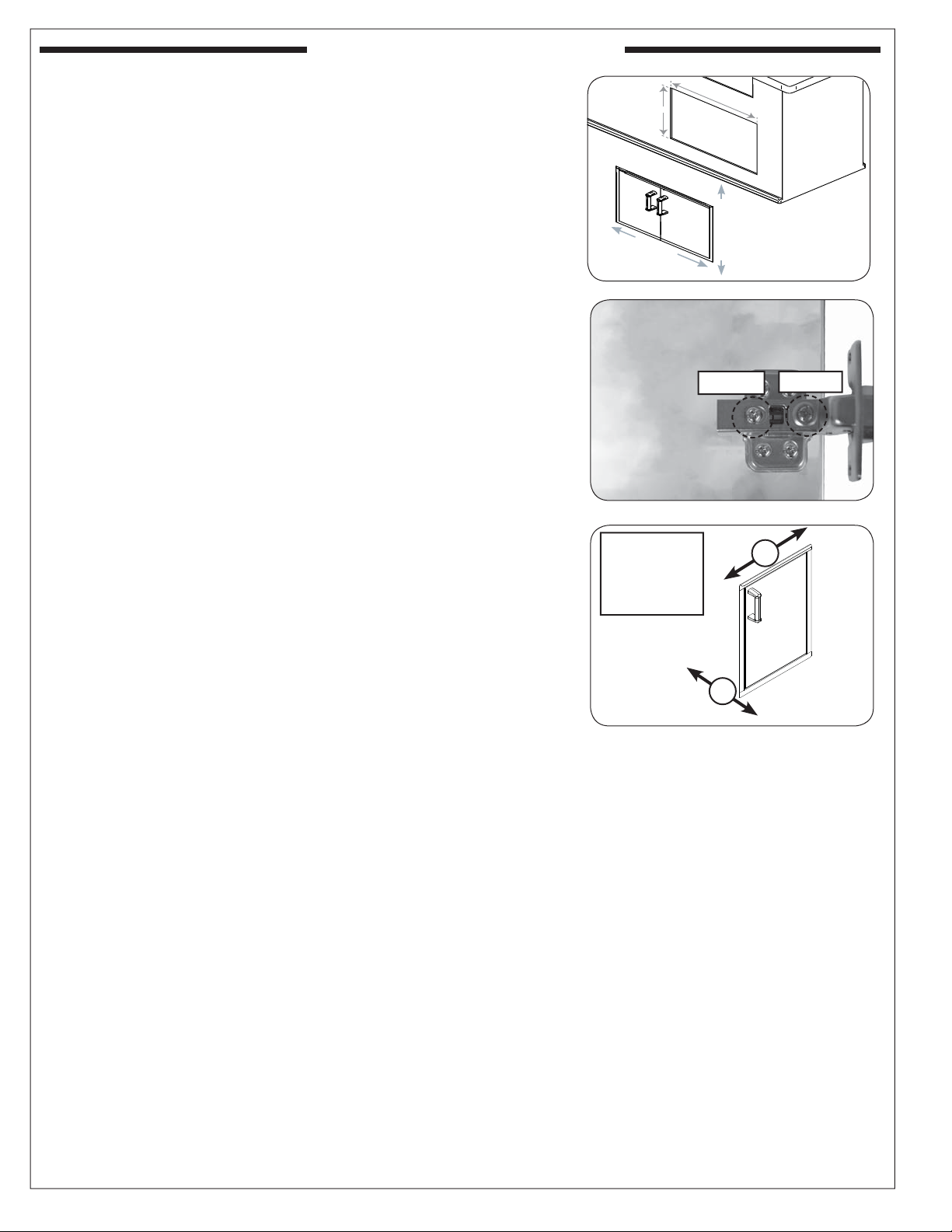
For doors with soft-close hinge:
Soft-close hinges have two door adjustment screws per hinge.
Screw "A" adjusts the door left or right. Turn clockwise to move
right and counterclockwise to move left, on both hinges. See Fig.
2-2. Screw "B" allows for the door to adjust inward or outward.
First loosen screw "B", adjust door as needed, then re-secure.
See Fig. 2-2.
For doors with propane tank trays:
To use, simply open the door, pull out the sliding cylinder tray,
place your cylinder on the tray and push the tray back in. The
cylinder is now ready for connection to your grill.
Important: Refer to any additional instructions included
with your door for the required installation
method of propane tank cylinders.
H
E
I
WIDTH
G
H
T
Fig. 2-1 Door cut-out diagram
Screw B Screw A
Fig. 2-2 Adjust door
Screw A: adjust
left/right
Screw B: adjust
inward/outward
A
B
Fig. 2-3 Adjust door
REV 4 - 1710261125
2
L-C2-358
Page 3
Drawer
support
Side View
Drawer
front
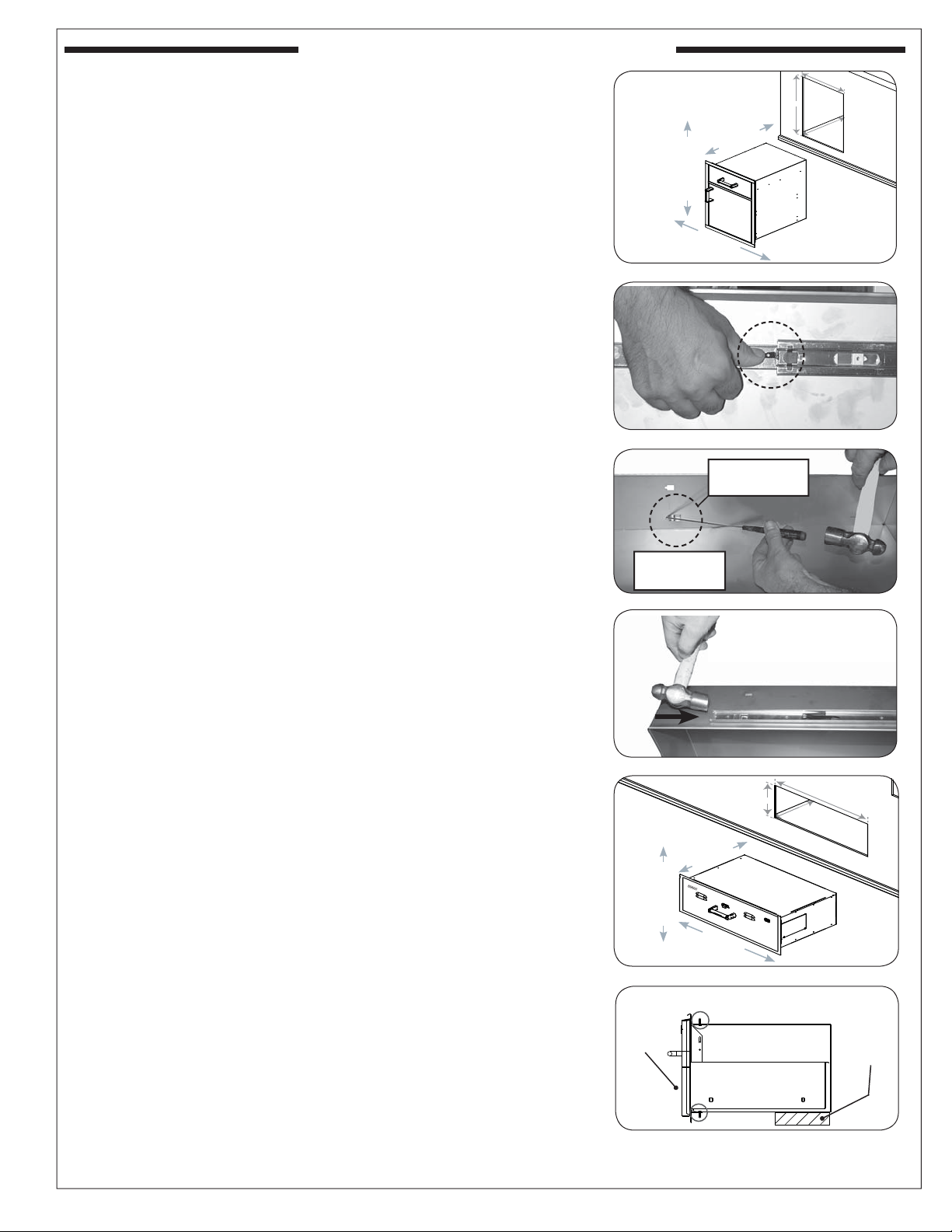
INSTALLATION GUIDELINES (cont.)
PANTRY
Installation Guidelines
Before installing your pantry, remove the drawer from its
base by completely pulling it out. Release the drawer from
the drawer slides by pressing the black lever down on the
right side, and up on the left side
on the drawer until it comes free of the runners.
1. Slide in and fasten the unit securely into the island
enclosure using the appropriate hardware for your
construction (not supplied) through the installation holes
in the top, sides, and bottom of the unit.
Important: Install using
3
screws are fl ush.
2. To re-attach the drawer; extend the drawer slides
completely and align the drawer into the slides, pushing
the drawer closed. Open the drawer to verify that it has
locked in place.
Note: DO NOT damage gasket while installing the screws.
Inner Drawer Height Adjustment
The top inner-drawer height can be adjusted (lowered) by
raising the drawer runners.
1. Pull out the drawer completely (see above section).
2. From the interior of the drawer, use a fl at head
screwdriver and a hammer to tap the runners free
(through the notches). See Fig. 3-3.
3. Align each runner over the alternate notches and use
the hammer to gently tap into place (see Fig. 3-4).
4. Reinstall the drawer.
DRAWER
Before installing your drawer, remove the drawer from its
base by completely pulling it out. Release the drawer from
the drawer slides by pressing the black lever down on the
right side, and up on the left side
on the drawer until it comes free of the runners.
1. In order to properly support the weight of your drawer, it
is necessary to provide a secure, level surface in the rear
of the unit (see
using bricks, 2 X 4’s, etc. Be sure that the height of this
rear support is 1/8" higher than that of the front opening
support, so that your drawer sits level.
2. Slide in and fasten the unit securely into the island
enclosure using the appropriate hardware for your
construction (not supplied) through the installation screw
slots in the top and bottom of the unit.
3. To re-attach the drawer; extend the drawer slides
completely and align the drawer into the slides, pushing
the drawer closed. Open the drawer to verify that it has
locked in place.
Fig 3-6
(Fig 3-2). Then pull outward
/16" countersink screws. Ensure
(Fig 3-2). Then pull outward
). This may be accomplished by
H
DEPTH
E
I
G
H
T
WIDTH
Fig. 3-1 Pantry cut-out diagram
Fig. 3-2 Releasing drawer from slides
Hammer
through notch
(Interior of
the drawer)
Fig. 3-3 Release tracking from drawer
Fig. 3-4 Reinstall runners
DEPTH
H
E
I
G
H
T
WIDTH
Fig. 3-5 Drawer cut-out diagram
REV 4 - 1710261125
Fig. 3-6 Drawer Installation (Side View)
3
L-C2-358
Page 4

FLUSH-MOUNTED DOORS, DRAWERS, & PANTRY
Cut-out is height x width x depth
DOUBLE DOORS WITH DUAL DRAWERS
MODEL:
CUT-OUT:
53930SC-22
21” x 30 ½” x 20 ½”
ELECTRIC WARMING DRAWER
MODEL:
CUT-OUT:
53830-SW
14 ½” x 32 ¼” x 22”
DOUBLE DOORS WITH TRASH
TRAY & DUAL DRAWERS
MODEL:
CUT-OUT:
TRIPLE ENCLOSED DRAWERS
MODEL:
CUT-OUT:
53930SC-12
21” x 30 ½” x 20 ½”
53803SC
26 ¼” x 14 ½” x 20 ½”
MASONRY DRAWER
MODEL:
CUT-OUT:
DOUBLE ENCLOSED DRAWERS
MODEL:
CUT-OUT:
(53802SC model shown)
53830SC
14 ½” x 32 ¼” x 22”
53802(H)SC
16” x 14 ½” x 20 ½”
SINGLE ACCESS DOOR*
MODEL:
CUT-OUT:
DOUBLE ACCESS DOORS
MODEL:
CUT-OUT:
(53938SC model shown)
REV 4 - 1710261125
53924SC-L
25” x 17 ½”
53938(H)SC
16” x 39”
DOUBLE ACCESS DOORS
MODEL:
CUT-OUT:
SINGLE DOOR WITH DUAL DRAWERS*
MODEL:
CUT-OUT:
53934SC
15” x 30”
53820SC-R
21” x 14 ½” x 20 ½”
Available in left or right hinge
*
4
ACCESS DOOR W/ DOUBLE
DRAWERS
MODEL:
CUT-OUT:
SINGLE ENCLOSED DRAWER
MODEL:
CUT-OUT:
53810SC
18 ½” x 30” x 26”
53801SC
5 ¼” x 14 ½” x 20 ½”
L-C2-358
Page 5

FLUSH-MOUNTED DOORS, DRAWERS, & PANTRY (cont.)
Cut-out is height x width x depth
DOUBLE ACCESS DOORS
MODEL:
CUT-OUT:
SINGLE ACCESS DOOR*
MODEL:
CUT-OUT:
53930SC
21” x 30”
53914SC-R
15” x 20 ½”
SINGLE ACCESS DOOR*
MODEL:
CUT-OUT:
(53920SC-L model shown)
DOUBLE ACCESS DOORS
WITH LOUVERS
MODEL:
CUT-OUT:
53920(H)SC-L
21” x 14 ½”
53930SC-1
21” x 30”
SINGLE ACCESS DOOR*
MODEL:
CUT-OUT:
ACCESS DOORS W/ PLATTER STORAGE
AND DOUBLE DRAWERS
MODEL:
CUT-OUT:
53816SC
18 ½” x 36½” x 26”
53917SC-R
18” x 24 ½”
PANTRY W/ TOP DRAWER
AND SINGLE DOOR W/ DUAL
DRAWERS (INSULATED)
MODEL:
CUT-OUT:
REV 4 - 1710261125
54020S
33 ½” x 20” x 26”
Also available: (not shown)
MODEL: 54018S
MODEL: 53820SC-L
MODEL: 53820(H)SC-TL or TR
MODEL: 53914SC-L
MODEL: 53917SC-L
MODEL: 53920(H)SC-R
MODEL: 53924SC-R
MODEL: 53930SC-12T
Available in left or right hinge
*
5
CUT-OUT: 25” x 17 ½” x 26”
CUT-OUT: 21” x 14 ½” x 20 ½”
CUT-OUT: 21” x 14 ½” x 20 ½”
CUT-OUT: 15” x 20 ½”
CUT-OUT: 18 ½” x 24 ½”
CUT-OUT: 21” x 14 ½”
CUT-OUT: 25” x 17 ½”
CUT-OUT: 21” x 30 ½” x 20 ½”
L-C2-358
Page 6

SELECT DOORS & DRAWERS
Cut-out is height x width x depth
ELECTRIC WARMING DRAWER
MODEL:
CUT-OUT:
TRIPLE DRAWERS
MODEL:
CUT-OUT:
33803
26 ¼” x 14 ½” x 20 ½”
33830-SW
13” x 31” x 20 ½”
MASONRY DRAWER
MODEL:
CUT-OUT:
DOUBLE DRAWERS
MODEL:
CUT-OUT:
33802
16” x 14 ½” x 20 ½”
33830-S
13” x 31” x 20 ½”
DOUBLE ACCESS DOORS
MODEL:
CUT-OUT:
DOUBLE DOORS WITH TANK TRAY
AND LOUVERS
MODEL:
CUT-OUT:
33930S
21” x 30”
33930S-12T
21” x 30 ½” x 20 ½”
REV 4 - 1710261125
SINGLE DOOR WITH DUAL DRAWERS*
MODEL:
CUT-OUT:
33820-SR
21” x 14 ½” x 20 ½”
*
Available in left or right hinge
ACCESS DOORS W/ PLATTER STORAGE
AND DOUBLE DRAWERS
MODEL:
CUT-OUT:
6
33816S
18 ½” x 36½” x 26”
L-C2-358
Page 7

SELECT DOORS & DRAWERS (cont.)
Cut-out is height x width x depth
SINGLE ACCESS DOOR*
MODEL:
CUT-OUT:
33914-SR
15” x 20 ½”
SINGLE ACCESS DOOR WITH TANK
TRAY AND LOUVERS*
MODEL:
CUT-OUT:
DOUBLE DOORS WITH 2 DRAWERS
MODEL:
CUT-OUT:
33820-TSL
21” x 14 ½” x 20 ½”
33930S-22
21” x 30 ½” x 20 ½”
SINGLE ACCESS DOOR*
MODEL:
CUT-OUT:
SINGLE ACCESS DOOR*
MODEL:
CUT-OUT:
33917-SR
18” x 24 ½”
33920-SR
21” x 14 ½”
REV 4 - 1710261125
SINGLE DRAWER
MODEL:
CUT-OUT:
33801
5 ¼” x 14 ½” x 20 ½”
ACCESS DOOR W/ DOUBLE DRAWERS
MODEL:
CUT-OUT:
Also available: (not shown)
MODEL: 33914-SL CUT-OUT: 15” x 20 ½”
MODEL: 33917-SL CUT-OUT: 18” x 24 ½”
MODEL: 33920-SL CUT-OUT: 21” x 14 ½”
MODEL: 33924-SR or SL CUT-OUT: 25” x 17 ½”
MODEL: 33920-1-SR or SL CUT-OUT: 21” x 14 ½”
MODEL: 33938S CUT-OUT: 16” x 39”
MODEL: 33820-SL CUT-OUT: 21” x 14 ½” x 20 ½”
MODEL: 33820-TSR CUT-OUT: 21” x 14 ½” x 20 ½”
MODEL: 33930S-12 CUT-OUT: 21” x 30 ½” x 20 ½”
Available in left or right hinge
*
7
33810S
18 ½” x 30” x 26”
L-C2-358
Page 8

LEGACY DOORS & DRAWERS
Cut-out is height x width x depth
MASONRY DRAWER
MODEL:
CUT-OUT:
SINGLE ACCESS DOOR (RIGHT OR LEFT)
WITH TANK TRAY AND LOUVERS
MODEL:
CUT-OUT:
23830-S
13” x 31” x 20 ½”
23920-1T-S
20 ½” x 14 ½” x 20 ½”
SINGLE ACCESS DOOR
MODEL:
CUT-OUT:
SINGLE ACCESS DOOR WITH LOUVERS
MODEL:
CUT-OUT:
23917-S
17 ½” x 24 ½”
23920-1-S
20 ½” x 14 ½”
SINGLE ACCESS DOOR
MODEL:
CUT-OUT:
DOUBLE ACCESS DOORS
MODEL:
CUT-OUT:
23920-S
20 ½” x 14 ½”
23930S
20 ½” x 30”
DOUBLE DOORS WITH DUAL DRAWERS
AND TRASH TRAY
MODEL:
CUT-OUT:
VENTING PANEL, LOUVERED STAINLESS STEEL
MODEL:
CUT-OUT:
OUTER DIMENSIONS:
REV 4 - 1710261125
23930S-12
21” x 30 ½” x 20 ½”
5510-01
5” x 12 ¾”
6” x 14”
Available in left or right hinge
*
SINGLE DOOR WITH DUAL DRAWERS
MODEL:
CUT-OUT:
23820-S
20 ½” x 14 ½” x 20 ½”
Also available: (not shown)
MODEL: 23912-S CUT-OUT: 12 ½” x 18 ½”
MODEL: 23918-S CUT-OUT: 18 ½” x 12 ½”
MODEL: 23924-S CUT-OUT: 24 ½” x 17 ½”
MODEL: 23914-S CUT-OUT: 14 ½” x 20 ½”
MODEL: 23912 CUT-OUT: 12 ½” x 18 ½”
MODEL: 23918 CUT-OUT: 18 ½” x 12 ½”
MODEL: 23924 CUT-OUT: 24 ½” x 17 ½”
MODEL: 23914 CUT-OUT: 14 ½” x 20 ½”
MODEL: 23917 CUT-OUT: 17 ½” x 24 ½”
MODEL: 23920 CUT-OUT: 20 ½” x 14 ½”
MODEL: 23920-1T CUT-OUT: 20 ½” x 14 ½” x 20 ½”
MODEL: 23920-1 CUT-OUT: 20 ½” x 14 ½”
8
L-C2-358
Page 9

CARE & CLEANING
By following these recommendations, you will enjoy the
beauty and convenience of your unit for many years to
come.
STAINLESS STEEL
Clean your unit by fi rst using stainless steel grill cleaner
to remove grease and dirt. Always wipe with the grain
(See Fig. 9-1). Next, apply stainless steel polish and
wipe down using polish wipes to restore the stainless
steel color.
If your unit is installed in a seaside (salt air) or poolside
(chlorine) location, it will be more susceptible to corrosion
and must be maintained/cleaned more frequently. Do not
store chemicals (such as chlorine or fertilizer) near your
stainless steel unit.
Due to the nature of stainless steel, surface iron oxide
deposits may appear. Do not be alarmed – these deposits
are removable with stainless-steel cleaner through prompt
and periodic maintenance. If not attended to promptly,
permanent pitting may occur.
Stainless
steel shown
Wipe with grain
Fig. 9-1
PORCELAIN
Doors that are porcelainized provide many years of
trouble-free service. These surfaces may be cleaned with
non-corrosive oven/grill cleaner, following manufacturer’s
instructions. For any stainless steel see above.
9
Page 10

U
L
SAFE USE & MAINTENANCE OF PROPANE GAS CYLINDERS
IMPORTANT FOR YOUR SAFETY
READ AND FOLLOW ALL WARNINGS PROVIDED WITH THE PROPANE-GAS CYLINDER.
When operating this appliance with a propane-gas cylinder, these instructions and warnings MUST be observed.
FAILURE TO DO SO MAY RESULT IN A SERIOUS FIRE OR EXPLOSION.
CYLINDER/CONNECTOR REQUIREMENTS
a. Propane-gas cylinders, valves, and hoses must be
maintained in good condition and must be replaced if
there is visible damage to either the cylinder or valve. If the
hose is cut or shows excessive abrasion or wear, it must
be replaced before using the gas appliance (see e.).
b. This unit, when used with a cylinder, should be connected
to a standard 5-gallon (20 lb.) propane-gas cylinder
equipped with an OPD (Overfi ll Prevention Device).
The OPD has been required on all cylinders sold since
October 1,1998, to prevent overfi lling.
c. Cylinder dimensions should be approximately 12" (30.5
cm) in diameter and 18" (45.7 cm) high. Cylinders must
be constructed and marked in accordance with the
Specifi cations for Propane Gas Cylinders of the U.S.
Department of Transportation (D.O.T.) or the National
Standard of Canada, CAN/CSA-B339, Cylinders,
Spheres, and Tubes for Transportation of Dangerous
Goods.
d. The cylinder used must include a collar to protect the
cylinder valve, and the cylinder supply system must be
arranged for vapor withdrawal.
e. The pressure regulator and hose assembly used must
e. The pressure regulator and hose assembly (Fig. 10-1)
match the specifi cation for Type I by ANSI Z 21.58/CGA
supplied with this outdoor gas appliance (L.P. models
1.6 (see Fig. 10-1).
only) must be used. Original and replacement pressure
regulator and hose assemblies must be those specifi ed by
the manufacturer for connection with a cylinder connecting
device identifi ed as Type I by the ANSI Z 21.58/CGA 1.6
(see PARTS LIST for ordering information).
f. The propane-gas cylinder valve must be equipped with a
cylinder connection coupling device, described as Type I
in the standard defi ned in paragraph e. above. This device
is commonly described as an Acme thread quick coupler.
g. If the propane-gas cylinder comes with a dust plug, place
the dust cap on the cylinder valve outlet whenever the
cylinder is not in use.
QUICK COUPLER OPERATION
To connect the regulator/hose assembly to the propanegas cylinder valve fi tting: Press the hand nut on the regulator
over the Acme thread fi tting on the cylinder valve. Turn the hand
nut clockwise to engage the threads and tighten until snug.
The use of pliers or a wrench should not be necessary. Only
cylinders marked “propane” may be used.
To disconnect: Turn the hand nut counterclockwise until
detached (Fig. 10-1).
Important: Before using the unit, and after each time the
cylinder is removed and reattached, check
the hose for wear (see a.) and check all
connections for leaks. Turn off the unit valves
and open the main cylinder valve, then check
connections with soapy water. Repair any
leaks before lighting the unit.
CAUTION: Always turn the propane cylinder main valve
off after each use, and before moving the unit
and cylinder or disconnecting the coupling.
This valve must remain closed and the
cylinder disconnected while the appliance
is not in use, even though the gas fl ow is
stopped by a safety feature when the coupler
is disconnected.
Carefully inspect the hose assembly each time before the
gas is turned on. A cracked or frayed hose must be replaced
immediately.
If the appliance is stored indoors, the cylinder must be
disconnected and removed. Disconnected
cylinders must be
stored outdoors, out of the reach of children, with threaded
valve plugs tightly installed, and must not be stored in a
building, garage, or any other enclosed area.
FOR YOUR SAFETY
a. DO NOT store a spare propane-gas cylinder under or
near this appliance.
b. NEVER fi ll the cylinder beyond 80-percent full.
c. IF THE INFORMATION IN a. AND b. IS NOT FOLLOWED
EXACTLY, A FIRE CAUSING DEATH OR SERIOUS
INJURY MAY OCCUR.
Fig. 10-1 Type I Acme thread quick coupler
QCC
Type 1
valve
Pressure
relief
valve
Hand wheel
Brass Acme
thread fi tting
Liquid level
indicator
(optional)
Hand nut with Acme
thread
Regulator
Vent
Hose
ENCLOSURE REQUIREMENTS
FOR YOUR SAFETY, you must provide the openings listed below for replacement air and ventilation of the unit enclosure. One
side of the enclosure shall be left completely open to the outside; OR 4 (minimum) ventilation openings MUST be created:
• Each opening must have a minimum of 10 sq. in. of free area. The openings must be equally sized.
• Two openings must be in the side walls of the enclosure, at the top level, and spaced at a minimum of 90 degrees. The openings
must begin 1" or less below the countertop level and end no more than 5" below the countertop level.
• Two openings must be in the side walls of the enclosure, at the fl oor level, and spaced at a minimum of 90 degrees. The openings
must begin 1" or less above the fl oor level and end no more than 5" above the fl oor level.
• The openings must remain unobstructed: The clearance between the openings and any items outside of the enclosure is
a minimum of 6". The clearance between the openings and any items within the enclosure is a minimum of 2".
It is acceptable to use RHP venting panels (PN 5510-01). Contact your dealer.
KEEP THE REQUIRED VENT OPENINGS AND SURROUNDING AREA OF THE ENCLOSURE CLEAR AND FREE AT ALL TIMES.
WARNING: Ventilation openings in side walls shall not communicate directly with other enclosures of the outdoor cooking gas appliance.
10
 Loading...