

Page 1
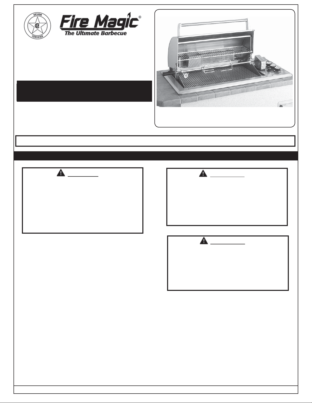
REGAL I DROP-IN
SERIES 34
OUTDOOR GAS BARBECUE
INSTALLATION AND OPERATING
INSTRUCTIONS
INSTALLER: Leave these instructions with consumer.
CONSUMER: Retain for future reference.
Important: READ THESE INSTRUCTIONS CAREFULLY BEFORE STARTING INSTALLATION
SAFETY WARNINGS & CODES
DANGER
IF YOU SMELL GAS:
1. Shut off the gas to the appliance.
2. Extinguish any open fl ame.
3. Open lid if equipped with an oven.
4. If odor continues, keep away from the
appliance, and immediately call your gas
supplier or fi re department.
CODE AND SUPPLY REQUIREMENTS: This
barbecue must be installed in accordance with local
codes and ordinances or, in the absence of local
codes, with either the current National Fuel Gas
Code (ANSI Z223.1NFPA 54), Natural Gas and
Propane Installation Code (CSA B149), or Propane
Storage and Handling Code (CSA B149.2).
Photo shows unit with optional
backburner & oven.
WARNING
1. Do not store or use gasoline, or other
fl ammable vapors and liquids, in the
vicinity of this or any other appliance.
2. A propane cylinder not connected for use
shall not be stored in the vicinity of this
or any other appliance.
WARNING
Improper installation, adjustment, alteration,
service, or maintenance can cause injury or
property damage. Refer to this manual. For
assistance or additional information consult
a qualifi ed, professional installer, service
agency, or the gas supplier.
This appliance and its individual shutoff valves must
be disconnected from the gas supply piping system
when testing the system at pressures in excess of
½ psig (3.5 kPa).
This appliance must be isolated from the gas supply
piping system by closing its individual manual
shutoff valves during any pressure testing of the
gas supply system at pressures up to and including
½ psig (3.5 kPa).
Robert H. Peterson Co. • 14724 East Proctor Avenue • City of Industry, CA 91746
REV 2 - 0609190904
Certifi ed to ANSI: Z21.58
All electrical outlets in the vicinity of the barbecue
must be properly grounded in accordance with local
codes or, in the absence of local codes, with the
National Electrical Code, ANSI/NFPA 70, or the
Canadian Electrical Code, CSA C22.1, whichever
is applicable.
CAUTION: Keep all electrical supply cords and
fuel supply hoses away from any
heated surface.
1
L-C2-00506
Page 2
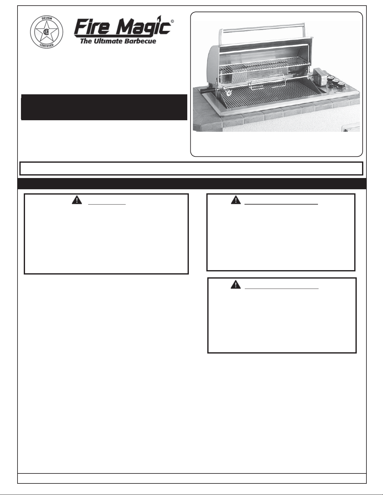
BARBECUE EXTÉRIEUR De GAZ
De la SÉRIE 34 MAJESTUEUX De I
DROP-IN
INSTALLATION ET CONSIGNES
D’UTILISATION
INSTALLATEUR : Laissez ces instructions avec le
consommateur.
CONSOMMATEUR : Maintenez pour la future
référence.
Important: LISEZ CES INSTRUCTIONS SOIGNEUSEMENT AVANT DE COMMENCER L’INSTALLATION
AVERTISSEMENTS ET CODES DE SÛRETÉ
La photo montre l’unité avec le
backburner et le four facultatifs.
DANGER
SI VOUS SENTEZ LE GAZ :
1. Coupez le gaz à l’appareil.
2. Éteignez-vous n’importe quelle fl amme nue.
3. Ouvrez le couvercle si équipé d’un four.
4. Si l’odeur continue, gardez loin de l’appareil,
et appelez immédiatement votre département
de fournisseur ou de feu de gaz.
CONDITIONS DE CODE ET
D’APPROVISIONNEMENT : Ce barbecue doit être
installé selon des codes et des ordonnances locaux
ou, en l’absence des codes locaux, avec le code
national courant de gaz de carburant (norme ANSI
Z223.1NFPA 54), gaz naturel et code d’installation
de propane (CSA B149), ou stockage de propane
et le code de manipulation (CSA B149.2).
Cet appareil et ses différents robinets d’isolement
doivent être démontés du système siffl ant d’offre
de gaz en examinant le système aux pressions
au-dessus du ½ psig (kPa 3.5).
Cet appareil doit être isolé dans le système
siffl ant d’offre de gaz par fermeture ses différents
robinets d’isolement manuels pendant tous les
essais sous pression du circuit d’alimentation de
gaz aux pressions jusques et y compris le ½ psig
(kPa 3.5).
Robert H. Peterson Co. • 14724 East Proctor Avenue • City of Industry, CA 91746
REV 2 - 0609190904
AVERTISSEMENT
1. Ne stockez pas ou n’employez pas
l’essence, ou d’autres vapeurs et liquides
infl ammables, à proximité de ceci ou
d’aucun autre appareil.
2. Un cylindre de propane non relié pour
l’usage ne sera pas stocké à proximité
de ceci ou d’aucun autre appareil.
AVERTISSEMENT
L’installation inexacte, l’ajustement, le changement,
le service, ou l’entretien peuvent causer des
dommages ou des dégats matériels. Référezvous à ce manuel. Pour l’aide ou l’information
additionnelle consultez un installateur qualifi é
et professionnel, l’agence de service, ou le
fournisseur de gaz.
Certifi é à la norme ANSI : Z21.58
Toutes les sorties électriques à proximité du
barbecue doivent être correctement fondues selon
des codes locaux ou, en l’absence des codes locaux,
avec Code électrique national, ANSI/NFPA 70,
ou le code électrique canadien, CSA C22.1, celui
qui est applicable.
ATTENTION: Maintenez tous les cordes
d’alimentation électrique et tuyaux
d’approvisionnement en carburant
partis de n’importe quelle surface
de chauffage.
2
L-C2-00506
Page 3
TABLE OF CONTENTS
SAFETY WARNINGS & CODES 1
TABLE OF CONTENTS 3
PRODUCT DATA TABLE 3
PARTS LIST 5
FIRE MAGIC REGAL I DROP-IN SERIES GAS BARBECUE (w/BACKBURNER) PARTS LIST 6
FIRE MAGIC REGAL I DROP-IN BACKBURNER & OVEN PARTS LIST (WHERE FITTED) 7
PLANNING FOR INSTALLATION OF YOUR REGAL I DROP-IN SERIES BARBECUE 8
WHERE TO INSTALL YOUR GAS BARBECUE 8
INSURING PROPER COMBUSTION AIR AND VENTILATION 8
EXHAUST REMOVAL 8
ELECTRICAL OUTLETS 8
SAFE USE & MAINTENANCE OF PROPANE GAS CYLINDERS 9
CYLINDER AND CONNECTOR REQUIREMENTS AND SPECIFICATIONS 9
INSTALLING YOUR FIRE MAGIC REGAL I DROP-IN SERIES BARBECUE 11
CHECKING AND CONVERTING GAS TYPE 12
CHECKING AND CONVERTING THE REGULATOR 12
CHECKING/CONVERTING THE BURNER ORIFICES 13
MAIN BURNER AIR SHUTTER ADJUSTMENT 13
CHECKING/CONVERTING THE BURNER ORIFICES (Cont.) 14
AIR SHUTTER ADJUSTMENT 15
MAIN BURNER AIR SHUTTER ADJUSTMENT 15
BACKBURNER AIR SHUTTER ADJUSTMENT 15
BARBECUE SAFETY INFORMATION & MAINTENANCE 16
DRIP COLLECTION SYSTEM 16
LIGHTING (IGNITION) INSTRUCTIONS 17
MANUAL LIGHTING 17
ROTISSERIE INSTRUCTIONS 19
USING YOUR BACKBURNER AND ROTISSERIE 19
REPLACING THE IGNITOR BATTERY 20
TROUBLESHOOTING 20
ACCESSORIES 21
USING THE GRILL SCRAPER 21
USING THE COOKING GRILL LIFTER 21
WARMING RACK 21
BARBECUE CARE & CLEANING 23
BARBECUE COVER 23
FIRE MAGIC OUTDOOR GAS BARBECUES LIMITED WARRANTY 24
PRODUCT DATA TABLE
Specifi cation
Counter Opening Height*
Counter Opening Width*
41 1/2" (105.4 cm)
Counter Opening Depth*
Main Burner
BTU per burner pair
Natural Gas Orifi ce
Propane Gas Orifi ce
Tools required for installation
• #2 medium size adjustable wrenches or pliers
3
•
• Pipe joint compound resistant to all glasses
Note:
REV 2 - 0609190904
/
" (.95 cm) wrench or
8
3
/
" (.95 cm) socket if orifi ce change is required.
8
#52 (part# 3001-52)
#61 (part# 3001-61)
3
/
8
Value
20 1/2" (52.1 cm)
18" (45.7 cm)
21,300 (6.2 kw)
" (.95 cm) socket screwdriver
Table 1 - Product Data Table
Specifi cation
Backburner
BTU per burner
Natural Gas Orifi ce
Natural Air Shutter
Propane Gas Orifi ce
Propane Air Shutter
*Note: If using an insulating liner
3
Value
22,000 (6.4 kw)
#42 (part# 3001-42)
5
/8 -inch gap (.63 cm)
#54 (part# 3001-54)
7
/
-inch gap (.49 cm)
16
consult liner instructions for
counter cut-out dimensions.
L-C2-00506
Page 4

AVERTISSEMENTS
Avertissements généraux :
• Ce barbecue est pour ultilisation à l’extérieur seulement. Si l’appareil est entreposé à l’intérieur,
enlever les bouteilles et les laisser à l’extérieur.
• Ne pas ranger le gril immédiatement aprés l’avoir utilisé. le laisser refroidir avant de le déplacer
ou de la ranger. Le non respect de cette mesure de sécurité pourrait entraîner un incendie
causant des dommages à la propriété, des blessures ou la mort.
• Ne pas utiliser cet appareil sous une surface combustible.
• Ne pas utiliser cet appareil sous un auvent. Le non respect de cette mesure de sécurité pourrait
entraîner un incendie ou des blessures.
• Dégagement minimal entre les parois latérales et l’arriére de l’appareil et la construction
combustible (45.7 cm à partir des parois latérales et 45.7cm à partir de l’arriére).
• Le régulareur de pression de gaz prévu avec cet appareil de cuisson à gaz pour l’extérieur
doit être utilisé. Ce régulateur est réglé pour une pression de sortie de 5 pouces de colonne
de l’eau pour le gaz naturel, et 10 pouces pour le propane.
• LE RÉGULATEUR INCLUS D’APPAREILS EST ÉVALUÉ POUR LE MAXIMUM DE 1/2 (LIVRES
PAR POUCE CARRÉ). SI VOTRE OFFRE DE GAZ EST 1/2 PLUS GRAND QUE (LIVRES
PAR POUCE CARRÉ), UN RÉGULATEUR ADDITIONNEL DOIT ÊTRE INSTALLÉ AVANT LE
BARBECUE. VOIR LA SECTION DE CONDITIONS D’OFFRE DE GAZ POUR LA PRESSION
APPROPRIÉE D’OFFRE DE GAZ.
• Ne couvrez jamais la surface entière de cuisine ou de gril de gauffreuses ou de casseroles.
La surchauffe se produira et les brûleurs ne seront pas très performants quand la chaleur de
combustion est emprisonnée au-dessous de la surface à cuire.
• Ne pulvérisez jamais l’eau sur une unité chaude de gaz, comme ceci peut endommager des
composants de porcelaine ou de fer de fonte.
Avertissements de propane :
• Une fuite de GPL peut causer une incendie ou une explosion si enfl ammée entraînant des
blessures corporelles graves ou la mort.
• Communiquez avec le fournisseur de GPL pour les réparations ou pour disposer de qules
bouteille ou du GPL non utilisé.
REV 2 - 0609190904
4
L-C2-00506
Page 5
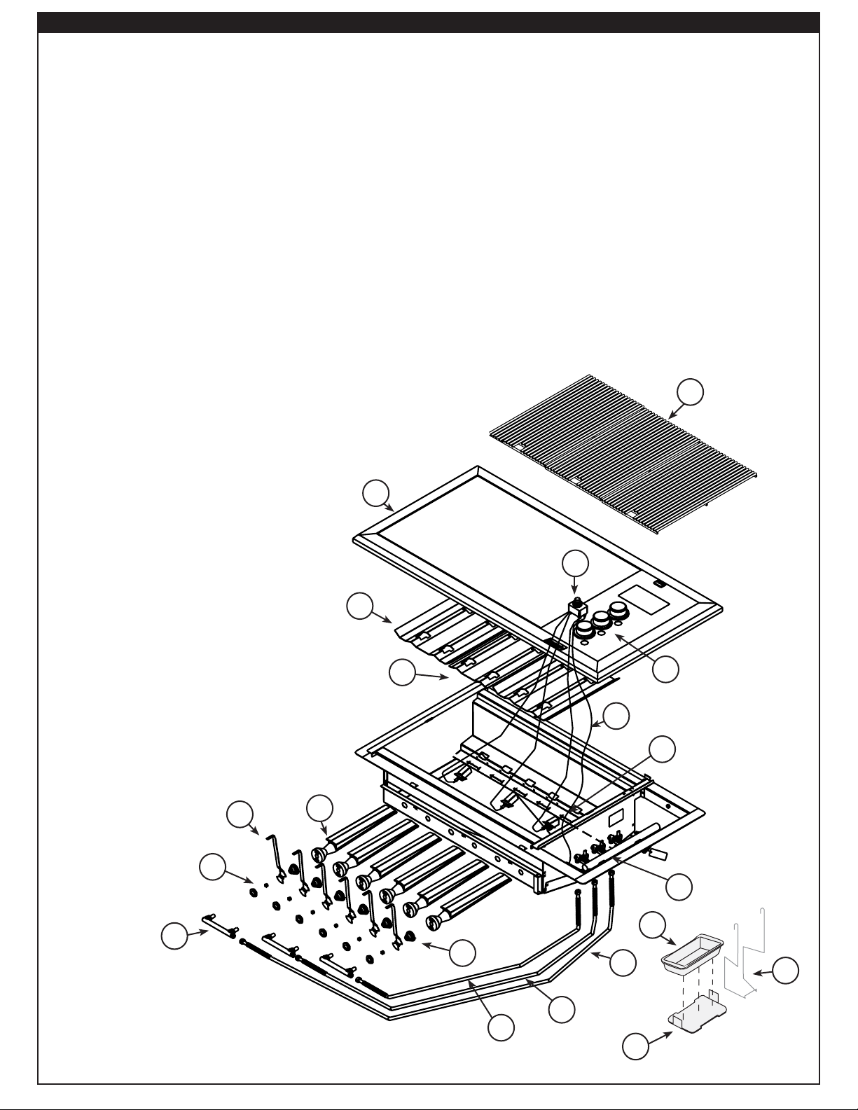
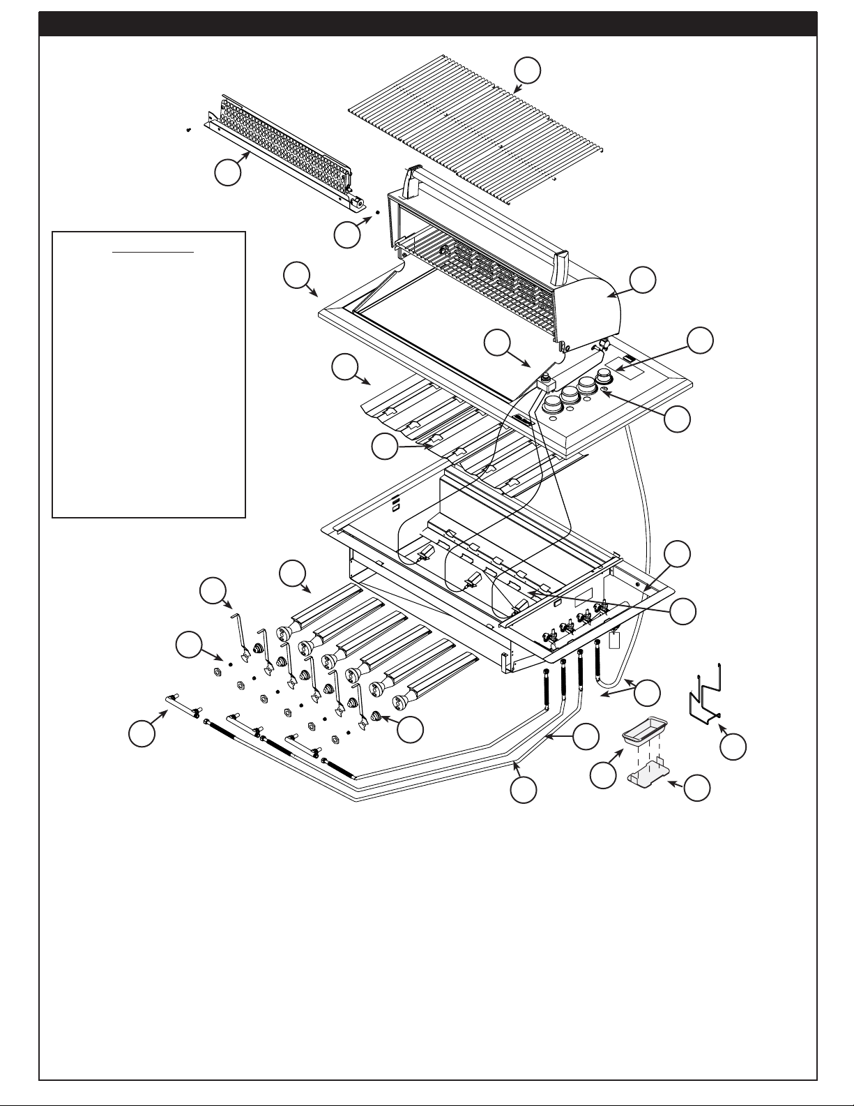
PARTS LIST
Item Description
1. TOP PANEL, REGAL I DRP-IN ,S.S
or TOP PANEL, REGAL I DRP-IN, PORCELAIN
2. 18"X10" PORCELAINIZED CAST IRON
GRIDS W / NON-STICK MATTE FINISH
or 18"X10" STAINLESS STEEL ROD GRID
3. FLAVOR GRID 7"
4. FLAVOR GRID 10" (2)
5. BURNER SHORT 304 CST SS, L/PKG (3)
6. SPRING, AIR SHUTTER (3)
7. AIR SHUTTER, DROP-IN REGAL (3
8. ORIFICE, 11/32-32 NAT GAS (SEE PRODUCT
DATA FILE)
or ORIFICE, 11/32-32 PROPANE GAS (SEE
PRODUCT DATA FILE)
9. VALVE MANIFOLD W/VALVE & REGULATOR
10. MANIFOLD BURNER, BRASS (3)
11. ASSY, 15.5" FLEX TUBE
12. ASSY, 34" FLEX TUBE
13. ASSY, 48" FLEX TUBE
14. KNOBS, REGAL DROP-IN (3)
15. IGNITOR ASSEMBLY
16. GROUND WIRE
17. ASSY, ELECTRODE COLLECTOR
18. DRIP PAN HOLDER
19. DRIP PAN SUPPORT
20. DRIP PAN, DISPOSABLE
1
2
Replacement parts can be ordered
from your local Fire Magic dealer.
7
8
10
15
3
4
16
5
6
13
14
17
9
20
19
REV 2 - 0609190904
12
11
18
5
L-C2-00506
Page 6
FIRE MAGIC REGAL I DROP-IN SERIES GAS BARBECUE (w/BACKBURNER) PARTS LIST
4
2
IMPORTANT
This Fire Magic oven
and backburner are fully
pre-assembled and tested at
the factory.
DO NOT attempt to remove
the oven and backburner
(optional) from the
barbecue prior to or during
installation or damage to
the connecting gas line and
ignitor wiring may occur.
The plastic straps that
secure the oven (optional)
to the barbecue unit must
be removed and discarded
prior to lighting.
9
11
3
20
1
18
5
19
6
13
7
17
10
12
Item Description
1. ASSY, OVEN W/BB S.S. OR PORCELAIN
2. BACKBURNER ASSEMBLY
3. TOP PANEL, REGAL I DRP-IN ,S.S.
or TOP PANEL, REGAL I DRP-IN, PORCELAIN
4. 18"x10" PORCELAINIZED CAST IRON GRIDS W / NONSTICK MATTE FINISH (3)
or 18"X10" STAINLESS STEEL ROD GRID (3)
5. FLAVOR GRID 7" (1)
6. FLAVOR GRID 10" (2)
7. BURNER SHORT 304 CST SS, L/PKG
8. SPRING, AIR SHUTTER (3)
9. AIR SHUTTER, DROP-IN REGAL (3)
10. ORIFICE, 11/32-32 NAT GAS (SEE PRODUCT DATA FILE)
or ORIFICE, 11/32-32 PROPANE GAS (SEE PRODUCT DATA
FILE)
8
Item Description
11. ORIFICE, BACKBURNER, #42 NAT GAS
or ORIFICE, BACKBURNER, #54 PROPANE
12. MANIFOLD BURNER, BRASS (3)
13. VALVE MANIFOLD W/VALVE & REGULATOR
or TOP PANEL, REGAL I DRP-IN, PORCELAIN
14. ASSY, 48" FLEX TUBE
15. ASSY, 34" FLEX TUBE
16. ASSY, 15.5" FLEX TUBE
17. ASSY, ELECTRODE COLLECTOR
18. KNOB, BACKBURNER, REGAL DROP-IN (1)
19. KNOBS, REGAL DROP-IN (3)
20. IGNITOR GENERATOR
21. DRIP PAN HOLDER
22. DRIP PAN SUPPORT
23. DRIP PAN, DISPOSABLE
16
15
14
22
23
21
REV 2 - 0609190904
6
L-C2-00506
Page 7
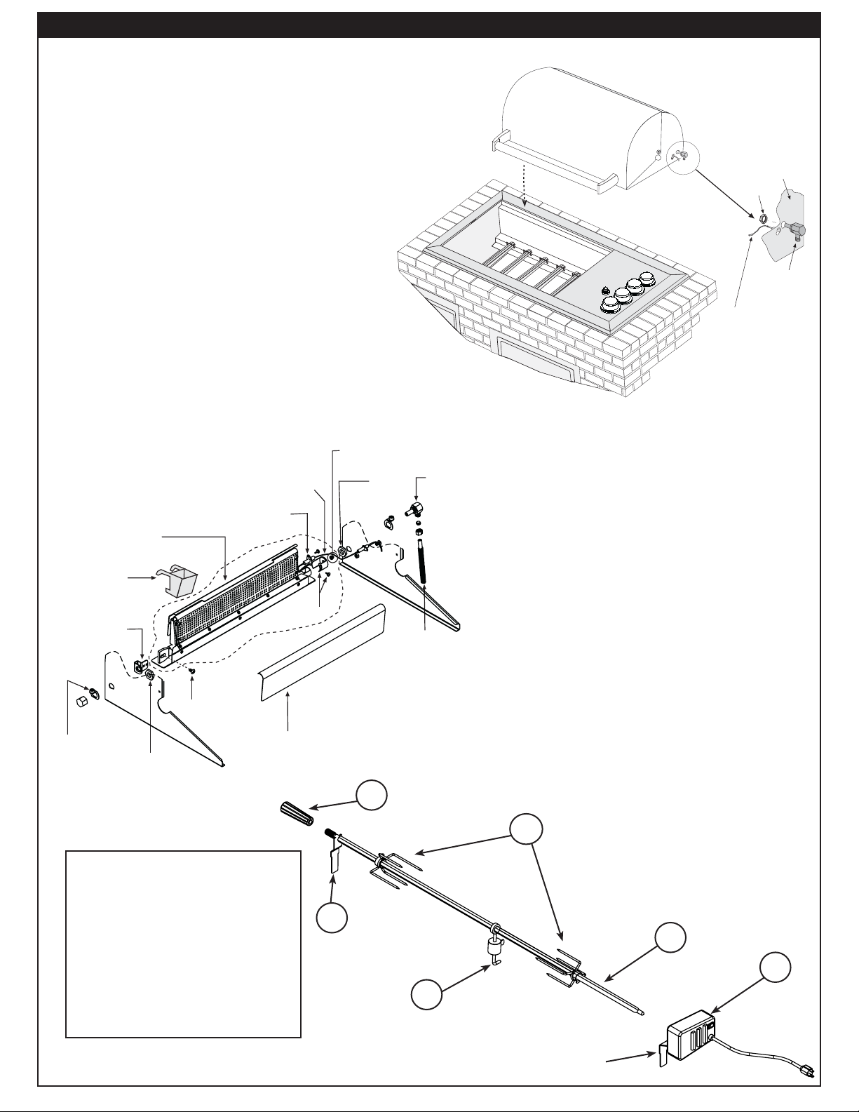
FIRE MAGIC REGAL I DROP-IN BACKBURNER & OVEN PARTS LIST (WHERE FITTED)
e
s
Important: Your Fire Magic barbecue, oven and
backburner (where fi tted) are fully
pre-assembled and tested at the
factory.
Do not attempt to remove the oven and backburner from
the barbecue prior to or during installation. Damage to
the connecting gas line and ignitor wiring may occur.
The plastic straps that secure the oven to the barbecue
unit should be removed and discarded prior to
lighting.
PARTS INCLUDED WITH THE BACKBURNER ASSEMBLY ARE INSIDE THE BROKEN LINE
EXPLODED VIEW OF BACKBURNER ASSEMBLY
Orifice, LP
wire
or Orifice, NG
3/4” Pal nut
4732-07
Electrode
EL-34
Elbow (lid stop)
IGNITOR
Ignitor
ELECTRODE
electrode
WIRE
wire
PAL NUT
Pal nut
El-34, elbow
& orifi ce
OVEN
Oven
EL-34, ELBOW
& ORIFICE
Backburner assembly
4732-09
Woodchip smoker tray
4732-08
Mounting bracket
Screw , 10-32 x 3/8”, SS
3730-02
Oven lid stop
bumper (pair)
Item
3/4” Pal nut
Description
No.
1. Rotisserie motor with
mounting bracket attached
2. Spit prongs
3. Handle
4.
Spit rod
5
/
" hex
8
5. Counterbalance
6. Spit bracket
4199-69
Electrode double rod
w/electrode
Air shutter &
Adj. screw
Backburner cover
6
3030-01
Backburner gas lin
w/compression nut
& sleeves
3
2
4
1
5
REV 2 - 0609190904
Mounting
bracket
7
L-C2-00506
Page 8
PLANNING FOR INSTALLATION OF YOUR REGAL I DROP-IN SERIES BARBECUE
WHERE TO INSTALL YOUR GAS BARBECUE
Fire Magic barbecues are designed for outdoor use
only.
WARNING
Built-in models must be installed in masonry or other
type of fi reproof enclosure, unless an insulating liner is
purchased from the manufacturor. The unit alone is not
insulated, and therefore must be installed with 18" (45.7
cm) of side, front, and back clearance from unprotected
combustible materials, such as wood, plastic, or stucco
with wood framing.
Do not install this unit under unprotected fl ammable
surfaces. Do not install or use this appliance inside a
building, garage, or any other enclosed area, including
recreational vehicles and/or boats.
In order to install the unit within combustible materials
you must purchase and utilize the Regal drop-in
insulation liner kit. See instructions received with
your liner for directions on how to install.
This is a drop-in type unit designed to fi t into countertop
enclosures. The top panel of the unit is removable for gas
hookup, servicing and burner adjustment.
Note: This unit should be installed so that it can be
removed at a later date if factory service is
required. Any protrusion into the barbecue
enclosure may obstruct the frame and prevent
the unit from dropping into place (see GAS
SUPPLY PLUMBING REQUIREMENTS).
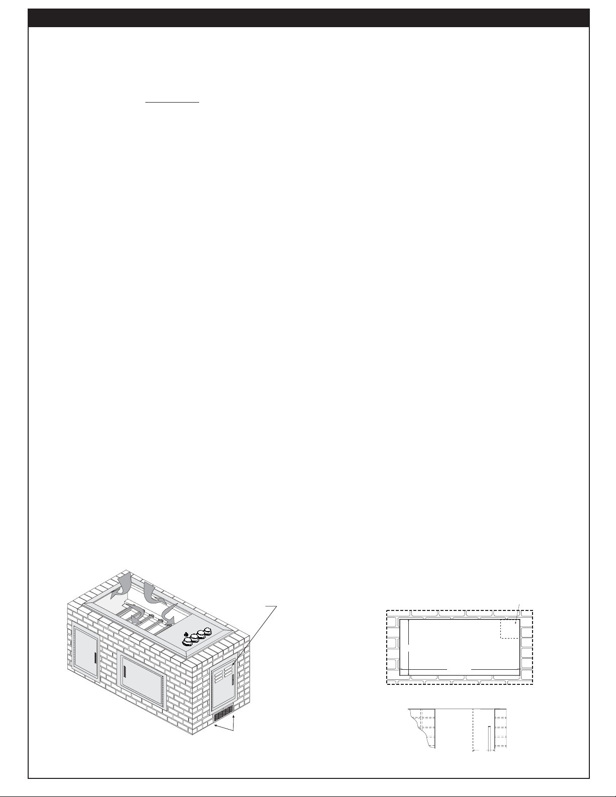
INSURING PROPER COMBUSTION AIR AND
VENTILATION
You must maintain proper air fl ow for your Fire Magic
barbecue to perform as it was designed (as shown, below,
Fig. 8-1). If airfl ow is blocked in any way, overheating
in
and poor combustion will result. Make sure not to block
the air inlet around the inside edges of the top panel.
Vents at
Vents at
cylinder level
Cylinder Level
EXHAUST REMOVAL
If installed under a patio roof, the grill area should
be fully covered by a chimney and exhaust hood. An
exhaust fan with a rating of up to 1000 CFM (472 liters
per second) or more may be necessary to effi ciently
remove smoke and other cooking by-products from the
covered area. Installation in fully-enclosed patio areas
is not recommended.
ELECTRICAL OUTLETS
All electrical outlets in the vicinity of the barbecue must
be properly grounded.
Note: Keep electrical supply cords away from all
heated surfaces.
GAS SUPPLY PLUMBING REQUIREMENTS
When natural gas is to be used, rigid 1/2" (1.3 cm) or 3/4"
(.75 cm) black steel pipe, or local code approved pipe for
temperatures up to 800°F (427°C), is required to conduct
the gas supply into the enclosure opening for connection
to the unit.
Note: An external valve (with a removable key) in
the gas line is necessary for safety when
your barbecue is not in use. It also provides
for convenient maintenance and repair.
Apply only joint compounds that are resistant to all
gasses on all male pipe fi ttings. Make sure to tighten
every joint securely. Do not use pipe joint compound to
connect fl are fi ttings. The gas supply pipe should enter
from the fl oor, or from the back or side wall in the right
rear corner of the barbecue enclosure, behind the valve
control zone. This pipe should terminate with a 1/2" (1.3
cm) male pipe thread, situated within 12" (30.5 cm) of
the countertop and no more than 6" (15.24 cm) from
the back and side walls.
GAS SUPPLY AND MANIFOLD PRESSURES:
For natural gas - normal 7" (17.78 cm) water column
(w.c.),
For propane gas - normal 11" w.c., minimum 10" (25.4 cm),
maximum 13" (33 cm).
minimum 5" (12.7 cm), maximum 10 1/2" (26.7 cm).
STUB OUT GAS PIPE
Stub out gas pipe
ANYWHERE IN THIS
anywhere in this area
AREA
BACK
BACK
20 1/2
5"
5"
Fig. 8-1 - Ventilation Diagram
REV 2 - 0609190904
Vents at
Vents at
Floor Level
fl oor level
41 1/2"
Counter top
COUNTER TOP
REAR
FRONT
Front
Fig. 8-2 - Gas stub diagram
8
Rear
L-C2-00506
Page 9

U
L
SAFE USE & MAINTENANCE OF PROPANE GAS CYLINDERS
IMPORTANT FOR YOUR SAFETY
READ AND FOLLOW ALL WARNINGS PROVIDED WITH THE PROPANE GAS CYLINDER.
When operating this appliance with a propane gas cylinder these instructions and warnings MUST be observed.
FAILURE TO DO SO MAY RESULT IN A SERIOUS FIRE OR EXPLOSION.
CYLINDER AND CONNECTOR
REQUIREMENTS AND SPECIFICATIONS
a. Propane gas cylinders and valves must be maintained in
good condition and must be replaced if there is visible
damage to either the cylinder or valve.
b. This barbecue, when used with a cylinder, should be
connected to a standard 5 gallon (20lb.) propane gas
cylinder equipped with an OPD (Overfill Prevention
Device). The OPD has been required on all cylinders sold
since October 1,1998 to prevent overfi lling.
c. Cylinder dimensions should be approximately 12"
(30.5cm) in diameter and 18" (45.7cm) high. Cylinders
must be constructed and marked in accordance with
the specifi cations for propane gas cylinders of the U.S.
Department of Transportation (D.O.T.) or the National
Standard of Canada,CAN/CSA-B339, Cylinders, Spheres
and Tubes for Transportation of Dangerous Goods.
d. The cylinder must include a collar to protect the cylinder
valve and the cylinder supply system must be arranged
for vapor withdrawal.
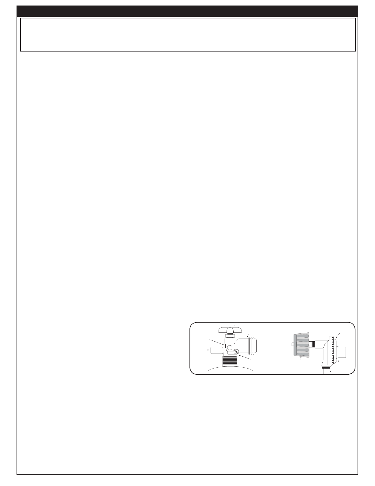
e. The pressure regulator and hose assembly (Fig. 9-1)
supplied with this outdoor cooking gas appliance must be
used. Original and replacement pressure regulator and
hose assemblies must be those specifi ed by the Robert
H. Peterson Co. for connection with a cylinder connecting
device identifi ed as Type I by the ANSI Z 21.58 and CGA
1.6-M95-1995 with Addenda ANSI Z 21.58a -1998 and
CGA 1.6a - M98.
f. The propane gas cylinder valve must be equipped with a
cylinder connection coupling device, described as Type
I in the standard defi ned in paragraph e. above. This
device is commonly described as an Acme thread quick
coupler.
g. If the propane gas cylinder comes with a dust plug, place
the dust cap on the cylinder valve outlet whenever the
cylinder is not in use.
QUICK COUPLER OPERATION
To connect the regulator/hose assembly to the propane
gas cylinder valve fi tting: Press the hand nut on the regulator
over the Acme thread fi tting on the cylinder valve. Turn the hand
nut clockwise to engage the threads and tighten until snug.
The use of pliers or a wrench should not be necessary. Only
cylinders marked propane must be used.
To disconnect: Turn the hand nut counter-clockwise until
detached (Fig. 9-1).
Important: Before using the barbecue, and after each
time the cylinder is removed and reattached,
check all connections for leaks. Turn off the
barbecue valves and open the main cylinder
valve, then check connections with soapy
water. Repair any leaks before lighting the
barbecue.
CAUTION: Always turn the propane cylinder main valve
off after each use, and before moving the
barbecue and cylinder, or disconnecting the
coupling. This valve must remain closed and
the cylinder disconnected while the appliance
is not in use, even though the gas fl ow is
stopped by a safety feature when the coupler
is disconnected.
Carefully inspect the hose assembly each time before the
gas is turned on. A cracked or frayed hose should be replaced
immediately.
If the appliance is stored indoors, the cylinder must be
disconnected and removed.
Cylinders must be stored out of
doors, out of the reach of children, and must not be stored
in a building, garage, or any other enclosed area.
FOR YOUR SAFETY
a. DO NOT store a spare propane gas cylinder under or near
this appliance.
b. NEVER fi ll the cylinder beyond 80 percent full.
c. IF THE INFORMATION IN “a” AND “b” IS NOT FOLLOWED
EXACTLY, A FIRE CAUSING DEATH OR SERIOUS
INJURY MAY OCCUR.
Fig. 9-1 Type I Acme thread quick coupler
QCC
Type 1
valve
Pressure
relief
valve
Handwheel
Brass Acme
thread fi tting
Liquid level
indicator
(optional)
Hand nut with Acme
thread.
Regulator
Vent
Hose
PROPANE CYLINDER ENCLOSURES
FOR YOUR SAFETY, you must provide the following openings below for drainage, replacement air, and cross ventilation of
any storage area exposed to possible leakage from gas connections, the barbecue, or propane cylinder:
One side of the gas cylinder enclosure left completely open to the outside OR by providing four (4) ventilation openings. Two
openings are to be at the cylinder valve level (approx. 16" (40.6 cm) above the fl oor) and on opposite walls of the enclosure.
Two more openings must be at the fl oor level on opposite sides of the enclosure. The fl oor level openings must start at the
fl oor and shall extend no higher than 5"(12.7 cm) above the fl oor. Each opening must have a minimum of 10 sq. in. (64.5
cm2) of free area. To achieve the proper ventilation, you may drill a series of holes, omit the grout from masonry joints, or
replace a brick with a hardware cloth screen. If the fl oor in the cabinet is raised and the space beneath the cabinet is open
to the outside, the lower ventilation openings may be in the fl oor.
Consult your gas supplier for ventilation and regulator requirements when connecting to a household propane supply.
9
Page 10
U
L
UTILISATION SÛRE ET ENTRETIEN DES CYLINDRES DE GAZ DE PROPANE
IMPORTANT POUR VOTRE SÛRETÉ
LISEZ ET SUIVEZ TOUS LES AVERTISSEMENTS ÉQUIPÉS DE VOTRE CYLINDRE DE GAZ DE PROPANE.
En actionnant cet appareil avec un cylindre de gaz de propane ON DOIT observer ces instructions et avertissements.
LE MANQUE DE FAIRE AINSI PEUT AVOIR COMME CONSÉQUENCE UNE INCENDIE OU UNE EXPLOSION SÉRIEUSE.
CYLINDRE ET CONDITIONS ET
CARACTÉRISTIQUES DE CONNECTEUR
a. Des cylindres et les valves de gaz de propane doivent être
maintenus en bon état et doivent être remplacés s’il y a
des dommages évidents au cylindre ou à la valve.
b. Ce barbecue, une fois utilisé avec un cylindre, devrait être
relié à un gallon de la norme 5 (20lb.) cylindre de gaz
de propane équipé d’un OPD (remplissez au-dessus du
niveau le dispositif d’empêchement). L’OPD a été exigé
sur tous les cylindres vendus depuis octobre 1.1998 pour
empêcher le remplissage excessif.
c. Les dimensions de cylindre devraient être approximativement
12"(30.5cm) de diamètre et 18" (45.7cm) hauts. Des
cylindres doivent être construits et marqués selon les
caractéristiques pour des cylindres de gaz de propane du
département des ETATS-UNIS du transport (D.O.T.) ou
le niveau national du Canada, du CAN/CSA-B339, des
cylindres, des sphères et des tubes pour le transport des
marchandises dangereuses.
d. Le cylindre doit inclure un collier pour protéger la valve
de cylindre et le circuit d’alimentation de cylindre doit être
assuré le retrait de vapeur.
e. Le régulateur de pression et l’ensemble de tuyau (
1
) fourni avec cet appareil à cuire extérieur de gaz doivent
fi g. 10-
être utilisés. Les régulateurs d’original et de pression de
remplacement et les ensembles de tuyau doivent être ceux
indiqués par le Robert H. Peterson Cie. pour le raccordement
avec un dispositif se reliant de cylindre identifi é comme type
I par la norme ANSI Z 21.58 et CGA 1.6-M95-1995 avec la
norme ANSI Z 21.58a -1998 d’addenda et CGA 1.6a - M98.
f. La valve de cylindre de gaz de propane doit être équipée
d’un dispositif d’accouplement de raccordement de
cylindre, décrit comme type I dans la norme défi nie dans le
e. de paragraphe ci-dessus. Ce dispositif est généralement
décrit comme coupleur rapide de fi l de point culminant.
g. Si votre cylindre de gaz de propane vient avec une prise
de la poussière, placez le bouchon anti-poussière sur la
sortie de valve de cylindre toutes les fois que le cylindre
n’est pas en service.
OPÉRATION DE COUPLEUR RAPIDE
Pour relier le regulator/hose à l’ajustage de précision de
valve de cylindre de gaz de propane: Serrez l’écrou de main
sur le régulateur au-dessus de l’ajustage de précision de fi l
de point culminant sur la valve de cylindre. Tournez l’écrou de
main dans le sens des aiguilles d’une montre pour engager les
fi ls et pour serrer jusqu’à ce que douillettement. L’utilisation des
pinces ou de la clé ne devrait pas être nécessaire. Seulement
le propane marqué par cylindres doit être employé.
Pour débrancher: Tournez l’écrou de main dans le sens
contraire des aiguilles d’une montre jusqu’à isolé (fi g. 10-1).
Important: Avant d’employer le barbecue, et ensuite
chaque fois que le cylindre est enlevé et
rattaché, examinez tous les raccordements
pour déceler les fuites. Arrêtez les valves
de barbecue et ouvrez la valve principale de
cylindre, puis vérifi ez les raccordements avec
de l’eau savonneux. Réparez toutes les fuites
avant d’allumer le barbecue.
ATTENTION: Tournez toujours la valve principale de cylindre
de propane au loin après chaque utilisation, et
avant de déplacer le barbecue et le cylindre,
ou débrancher l’accouplement. Cette valve doit
rester fermée et le cylindre a débranché alors
que l’appareil n’est pas en service, quoique
l’écoulement de gaz soit arrêté par un dispositif
de sûreté quand le coupleur est débranché.
Inspectez soigneusement l’ensemble de tuyau chaque fois
avant que le gaz soit allumé. Un tuyau criqué ou frangé devrait
être remplacé immédiatement.
Si l’appareil est stocké à l’intérieur, le cylindre doit être débranché
et enlevé. Des cylindres doivent être stockés hors des portes, hors
de l’extension des enfants, et ne doivent pas être stockés dans un
bâtiment, le garage, ou n’importe quel autre secteur inclus.
POUR VOTRE SÛRETÉ
a. Ne stockez pas un cylindre de gaz disponible de propane
dessous ou ne vous approchez pas de cet appareil.
b. Ne remplissez jamais cylindre au delà de 80 pour cent de
plein.
c. SI L’INFORMATION DANS “A” ET “B” N’EST PAS SUIVIE
EXACTEMENT, UN FEU CAUSANT LA MORT OU DES
DOMMAGES SÉRIEUX PEUT SE PRODUIRE.
Fig. 10-1 type coupleur rapide de fi l de point culminant d’I
Volant de commande
QCC
Type 1
Valve
Valve
de
décompression
Ajustage de précision
en laiton de fi l de
point culminant
Indicateur
de niveau
de liquide
(facultatif)
Écrou de main avec le
fi l de point culminant.
Régulateur
Passag e
Tuy au
CLÔTURES DE CYLINDRE DE PROPANE
POUR VOTRE SÛRETÉ, vous devez fournir les ouvertures suivantes ci-dessous pour le drainage, l’air de rechange, et la
ventilation en travers de n’importe quelle zone de stockage exposée à la fuite possible des raccordements de gaz, du barbecue,
ou du cylindre de propane:
Un côté de la clôture de cylindre de gaz a laissé complètement ouvert de extérieur OU en fournissant quatre (4) ouvertures de
ventilation. Deux ouvertures doivent être au niveau de valve de cylindre (approximativement 16" (40.6 centimètres) au-dessus
du plancher) et sur les murs opposés de la clôture. Deux ouvertures supplémentaires doivent être au niveau de plancher des
côtés opposés de la clôture. Les ouvertures de niveau de plancher doivent commencer au plancher et se prolongeront pas
plus haut que 5"(12.7 centimètre) au-dessus du plancher. Chaque ouverture doit avoir un minimum de 10 pouces carrés (64.5
2
cm
) du secteur libre. Pour réaliser la ventilation appropriée, vous pouvez forer une série de trous, omettez le coulis des joints
de maçonnerie, ou remplacez une brique avec un écran de tissu de matériel. Si le plancher dans le coffret est augmenté et
l’espace sous le coffret est ouvert d’extérieur, les ouvertures inférieures de ventilation peuvent être dans le plancher.
10
Page 11

INSTALLING YOUR FIRE MAGIC REGAL I DROP-IN SERIES BARBECUE
1. POSITION THE BURNERS FOR OPERATION
a. After checking orifice drill size, install the air
shutter spring and the air shutter over the orifi ce
holder fi tting in the order and position shown in
Fig. 11-1.
b. Carefully place the burner(s) back in position,
resting on the back fl ange of the inner liner so that
the brass orifi ce and orifi ce holder fi ttings project
well into the burners.
c. Replace all the burner hold down clips.
2. CONNECT THE GAS SUPPLY TO YOUR REGAL
I DROP-IN SERIES BARBECUE
The barbecue may be connected to the gas supply line
using a fl exible rubber hose of proper rating. However, it
must not be connected directly to the valve manifold
or damage to the hose will result from overheating.
Burner
This will cause a rupture or leak, resulting in an explosion
or serious injury.
A stainless steel fl exible connector (minimum 18" (45.7
cm) must be used between the valve manifold and the
rubber hose.
a. Make sure that your gas supply is turned OFF.
Then connect the 1/2" (1.27 cm) pipe adapter fi tting
supplied with the stainless steel fl ex connector
to the gas supply stub. Use pipe joint compound
that is resistant to all gasses on the male pipe
fi tting and tighten securely. Do not use pipe joint
compound to connect the fl are fi tting to the supply
stub adapter.
b. If you have not already done so, lower your
barbecue into place, making sure not to pinch or
kink the gas connector.
c. Bring the fl ex connector up to the valve manifold
Inlet.
Burner
manifold with
Burner neck
Spring
orifice holder
Burner clip
Air shutter
Orifice
Fig. 11-1 - Burner orifi ce diagram
d. Connect the fl ex connector to the fl are fi tting adapter on the manifold inlet. Support the manifold inlet fi tting with
a wrench to avoid applying excessive torque to the manifold assembly while tightening this connection securely.
Do not use pipe compound on the fl are fi tting.
e. Make sure the barbecue burner valves are in the OFF position. Turn the gas supply on. Then carefully check
all gas connections for leaks with a brush and soapy water before lighting. NEVER USE A MATCH OR OPEN
FLAME TO TEST FOR LEAKS.
f. Refer to the AIR SHUTTER ADJUSTMENT instructions and LIGHTING INSTRUCTIONS of this manual before
replacing the top panel and knobs.
g. Make sure the drip pan (provided with three disposable liners) is in place before replacing the top panel. In
order to change or empty the drip pan, you may access it when the top panel is off, or you may create a small
access door on the right side of your barbecue enclosure.
Note: Disposable liners (mini-loaf pans) are available at many
Flavor grid
stores. For your convenience, the drip pan holder is
designed so an empty 14 to 18 ounce (.41 lt to .53 lt) tin can
may be substituted for the drip pan and drip pan support.
h. Screw the two 1 1/4" (2.8 cm) stabilizer screws (packed with
the instructions) into the threaded inserts in the right rear
Flavor grid leg
Burner
corner of the frame assembly. This will secure your barbecue
in place.
i. Replace the top panel. Be sure to reattach the ignitor wires.
The top panel may be adjusted left to right for bezel alignment
with gas valve knobs.
j. Replace the burner control knobs.
3. INSTALL THE FLAVOR GRIDS
Place the fl avor grids directly on the burner making sure the legs
of the fl avor grids rests directly on the burner (
the grids over the burners with the open side up. This enables heat
Fig. 11-2). Center
Fig. 11-2 - Flavor grid diagram
from the burners to be evenly distributed throughout the cooking
area. Flavor grids heat and cool quickly, making your Fire Magic barbecue very responsive to the changes you specify
in grill temperature. The fl avor grids are made of a high grade type 304 temperature resistant stainless steel that is rust
proof and may be cleaned with standard oven cleaners.
11
Page 12
CHECKING AND CONVERTING GAS TYPE
This barbecue comes from the factory confi gured
for one type of gas as marked on the label behind
the barbecue face plate.
Converting this barbecue to burn a different
type of gas requires a conversion kit from the
factory. The professional installer that converts
this barbecue to burn a different gas must
perform the following functions:
1. Change replaceable, brass gas orifi ces (included at
original shipping) on each burner to match the new
gas type (see PRODUCT DATA TABLE, Table 1).
2. Switch the convertible gas regulator (included
at original shipping) to match the new gas type
(see below).
3. Plumb the unit to the new gas supply.
4. Apply a new label behind the faceplate, indicating
the new gas the barbecue will burn (included
with conversion kit).
WARNING
HAZARDOUS OVERHEATING WILL OCCUR IF A
NATURAL GAS ORIFICE IS USED WITH PROPANE
GAS. IF YOU ARE NOT SURE THE CORRECT
ORIFICES ARE INSTALLED, OR IF AN ORIFICE
CHANGE IS NECESSARY, REFER TO THE FOLLOWING
INSTRUCTIONS.
CAUTION: Make sure the barbecue is at a safe
temperature and isolated from gas and
electrical supplies before beginning the
tasks outlined below.
Note: The cooler the barbecue, the greater the
tolerances between the stainless steel parts,
and therefore, the easier to disassemble and
reassemble parts of the barbecue.
For your safety, exercise caution, and make sure you have
adequate hand protection, such as gloves, when handling
removable sheet metal parts of the barbecue.
CHECKING AND CONVERTING THE REGULATOR
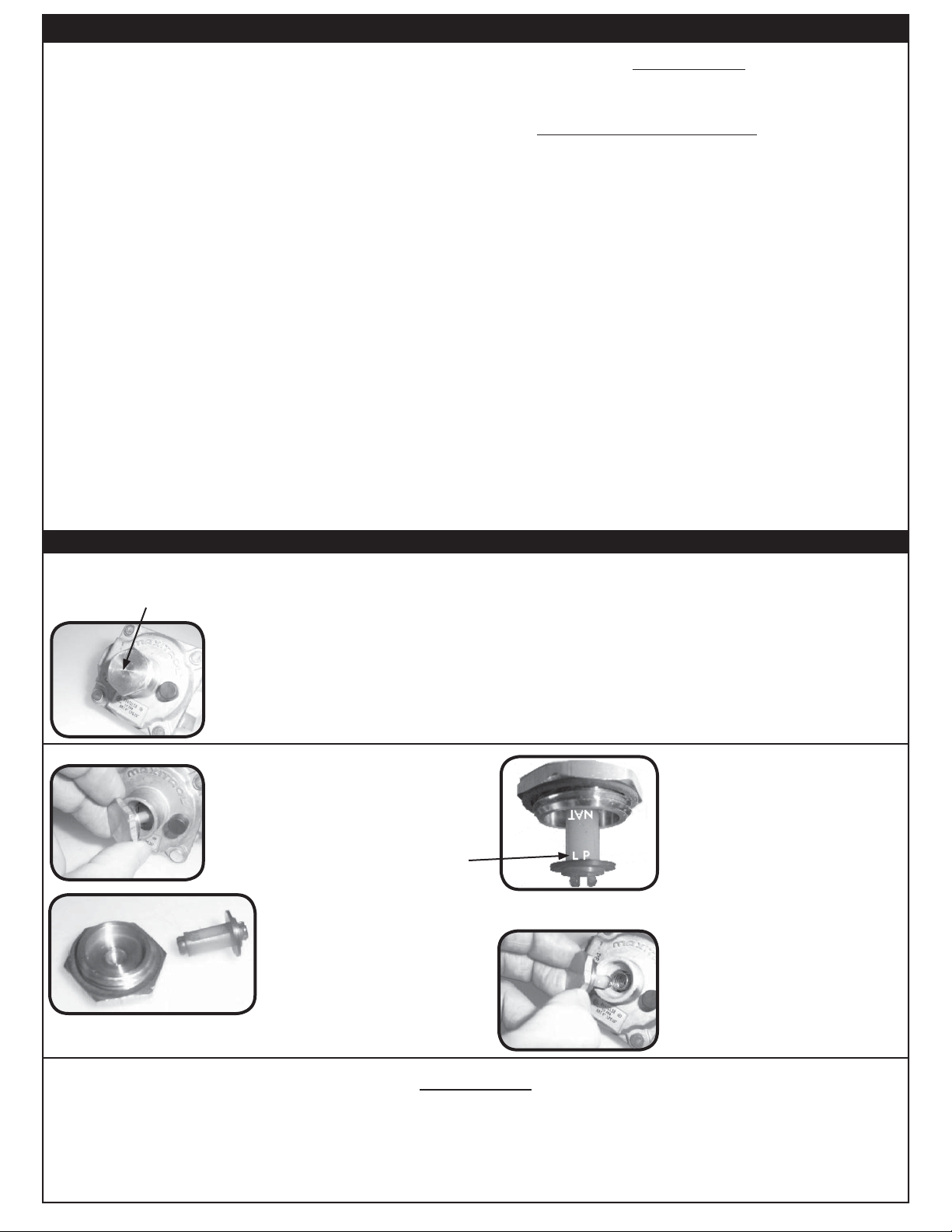
Barbecue regulator:
note the cap on top
STEP 1:
Unscrew and remove the cap from the
regulator, extracting the converter.
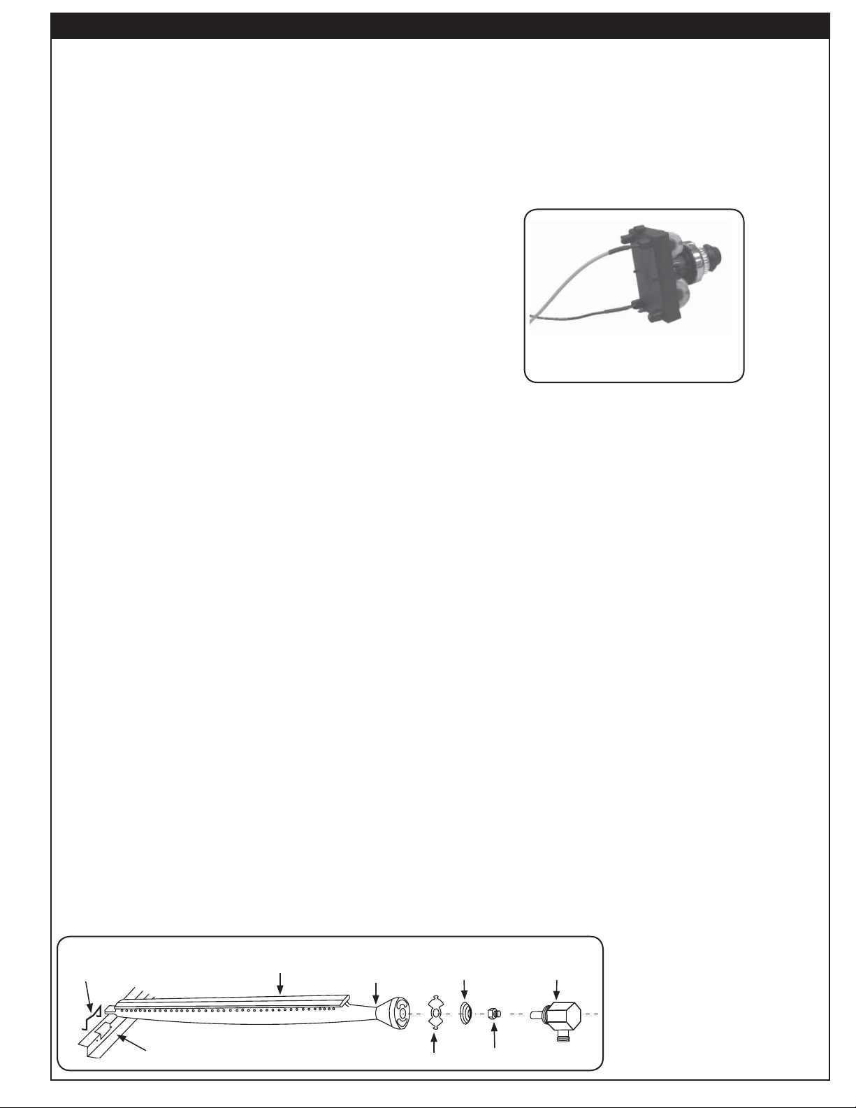
Note: Each end of the plastic converter is engraved with either the letters NAT or
L.P. (propane) for the respective gases. When the converter is in the cap
and the cap is held uppermost, the letters seen indicate the gas that the
regulator is set up for.
To convert the regulator from one gas to another follow steps 1-4.
STEP 3:
Turn the converter around
and replace carefully into the
center of the cap (it will snap
Read gas
type here
STEP 2:
Remove the converter (the
plastic stalk) by carefully
pulling it away from the center
of the cap (it will snap out of
its seating).
into place). Check that you can
read the type of gas the unit is
set for.
STEP 4:
Replace the unit into the
regulator and screw down
until snug.
WARNING
1
THIS APPLIANCE REGULATOR IS RATED FOR
1
GREATER THAN
BARBECUE. SEE GAS SUPPLY REQUIREMENTS SECTION FOR PROPER GAS SUPPLY
PRESSURE.
/2 PSI, AN ADDITIONAL REGULATOR MUST BE INSTALLED BEFORE THE
/2 PSI MAXIMUM. IF YOUR GAS SUPPLY IS
12
Page 13
CHECKING/CONVERTING THE BURNER ORIFICES
CHECK FUEL ORIFICES FOR PROPER SIZE
a. Your Regal I barbecue is equipped with fuel orifi ces
for natural gas, unless otherwise indicated. To use
with propane gas, you must install smaller orifi ces to
avoid hazardous overheating. Refer to the Product
Data Table 1 for the proper orifi ce size needed.
b. Remove the cooking grids and fl avor grids from your
barbecue.
c. If the gas supply has been connected, make sure the
burner valves are in the OFF position. Then carefully
pull the valve knobs from their stems.
Note: Carefully, but fi rmly, lift the top panel away from the
frame. The spark generator for the ignition system
is attached to the top panel. The ignitor need not
be detached, but the wires must be unplugged
from the generator before the panel is removed.
d. Using a fl at blade screwdriver, pry the burner retaining
clip from rear wall of the barbecue frame (see
Fig.10-
1). Remove the burner by; A) Pulling it to the front of
the barbecue; B) Lift the far end out of the notch; C)
Pull the burner away from the manifold, taking care not
to lose the air shutter and spring, which may become
detached when the burner is removed.
e. Using 3/8" (.95 cm) socket, remove the orifi ce from
the orifi ce holder on the burner manifold and check
the number stamped on the face. Repeat for each
burner as necessary.
Note: If you have the optional backburner, check the
backburner orifi ce for size.
Note: The air shutter must be re-adjusted after removing
the burner to assure proper combustion (see
section below).
6. Replace the burner by fi rst sliding the open end over the
new orifi ce and then lowering the back end down onto
the inner liner shelf at the back of the barbecue.
7. Reinsert the stainless steel clip using fi ngers or pliers
while holding down the back end of the burner.
8. Replace the fl avor grid and then the grill so that the cutout
section of the grill is in front.
Important The oven and backburner (where fitted)
are pre-installed at the factory and should
not be removed from the barbecue during
installation. Perform the following checks
before installing your barbecue:
MAIN BURNER AIR SHUTTER ADJUSTMENT
After removing the burner it will be necessary to adjust the
air shutter again. Refer to this section on MAIN BURNER AIR
SHUTTER ADJUSTMENT.
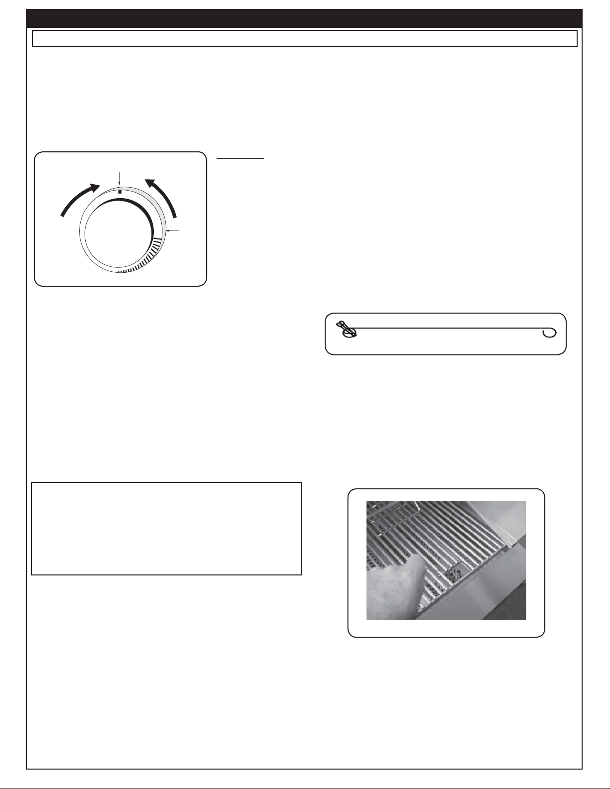
a. If you removed the face plate re-install the ignition wires.
Your barbecue may have either two (2) or four (4) wires
depending on the exact model. Pull the drip tray out. Lean
the face forward and plug the wires into the terminals
on the spark generator (Fig. 13-2). The wires can be
plugged into any terminal.
Important: Test the electrodes for spark before securing
the face to the frame (see also the section
REPLACING THE IGNITOR BATTERY).
Fig. 13-2
Spark generator
b. Replace the face on the frame so the front lip of the face
covers the lip on the frame. Re-secure the face with the
face fastener screws.
c. Replace the control knobs holder on the burner manifold
and check the number stamped on the face. Repeat for
each burner as necessary.
BACKBURNER ORIFICE SIZE CHECKING/
CONVERSION
Before beginning, make sure you have the proper tools for
the task.
This task requires:
• a #2 Phillips-head screwdriver
• a #2 fl at-head screwdriver
• a 3/8" (.95 cm) wrench or socket screwdriver
Note: It may be necessary to remove the rotisserie rod
before beginning this procedure.
1. Remove the heating rack, if installed, and set it aside.
2. Remove the backburner cover, if installed.
3. Unscrew both backburner face plate screws using a
Phillips-head screwdriver and set them aside.
4. Remove the backburner face plate by pulling the bottom
toward the front of the barbecue and rotating it upward
and outward until the two top tabs can be removed from
the back wall of the barbecue. Set it aside.
5. Remove the backburner assembly anchoring screw on
the lower left of the backburner using a Phillips-head
screwdriver and set it aside.
Repeat the above steps for each main burner. Then reinstall
the face plate.
Fig. 13-1 - Burner orifi ce diagram
Hold down clip
Inner liner
Burner
Burner neck
Air shutter
13
Spring
Burner manifold
Orifi ce
Page 14

CHECKING/CONVERTING THE BURNER ORIFICES (Cont.)
6. Pull the backburner assembly to the left, clear of
the orifi ce, and then rotate the top forward and
downward and lay it face down across the main
burner dividers.
CAUTION: Be careful not to damage the wires
connected to the backburner assembly.
7. Use the socket driver to remove the exposed orifi ce
and replace it with the correct orifi ce for the gas to be
burned (see Product Data Table 1 for correct orifi ce
sizes, based on burner type and gas type).
8. Replace the backburner assembly and re-insert the
anchoring screw. Center the backburner assembly
so that the backburner face place will fi t over it.
Tighten the anchoring screw using a Phillips-head
screwdriver.
9. While the backburner faceplate is still off, adjust
the backburner air shutter
opening size by loosening the
air shutter adjustment screw
with a flat-head screwdriver
and sliding the air shutter to
the position indicated in the
Product Data Table; then retighten the adjustment screw.
(see section on AIR SHUTTER
ADJUSTMENT).
10. Replace the backburner face plate by fi rst inserting
the upper tabs into the slots in the back wall of the
Air shutter
screw
Fig. 14-1
barbecue and then rotating the bottom downward
and inward.
11. Replace the two backburner faceplate screws using
a Phillips-head screwdriver.
Tip: Re-attaching the backburner faceplate may be
easier if the left screw is replaced before the right
screw.
THE BACKBURNER COVER
The backburner cover is installed by placing the curved
part of the cover over the top of the perforated portion
of the backburner (see Fig. 14-2). The cover should
be kept in place on the backburner when it is not in use.
This will keep your backburner free from grease splatter
and debris that may hinder its performance.
Important: You must remove the backburner cover
before lighting the backburner.
Fig. 14-2
Electrode
Air
shutter
Ignitor wire
Orifice
Air shutter
screw
Oven
(right side)
14
Page 15

AIR SHUTTER ADJUSTMENT
MAIN BURNER AIR SHUTTER ADJUSTMENT
Important: The air shutters must be adjusted
after installation. If not, this appliance
may not light, heat evenly, or cook
properly.
Main burner air shutters are easily accessed by
Main burner air shutters are easily accessed by
removing the front panel (face). The air shutters are
removing (when cool) the top panel (face). The air
located at the front of the burners behind the face
shutters are controlled by the wire levers at the front
(see PARTS LIST). The air shutter has a small dimple
of the burners (see PARTS LIST). The air shutter has
(see Fig.
a small dimple (see Fig.
in the burner face. This prevents the air shutter from
into notches in the burner face. This prevents the air
moving.
shutter from moving.
USE PROPERLY INSULATED TOOLS TO MAKE
ONLY ADJUST 2 AIR SHUTTERS AND THEIR
THESE ADJUSTMENTS. NEVER TOUCH A
CORRESPONDING BURNERS AT ONE TIME.
HOT BARBECUE DIRECTLY TO MAKE
SHUT OFF THE BURNERS PRIOR TO MOVING ON
1. Using the wire levers, close the air shutters
1. Using the tip of a long screwdriver, close the air
2. Light the corresponding burner pair in accordance
2. Light the barbecue in accordance with the
3. After burning for two (2) minutes, open the air
3. After burning for two (2) minutes, open the air
4. Begin closing the air shutters with the wire levers
4. Begin closing the air shutters with the tip of a
Note: You may then see short yellow tips on the
Note: You may then see short yellow tips on the
15-1), which allows it to lock into notches
ADJUSTMENTS.
TO THE NEXT SET.
by turning the tabs to a vertical position (Fig.
shutters by turning the tabs to a vertical position
15-2).
(Fig.
15-2).
with the LIGHTING INSTRUCTIONS and burn
LIGHTING INSTRUCTIONS and burn for 2
for 2 minutes with the knob on HI LIGHT and the
minutes with the knobs on HI LIGHT and the
oven open.
oven open.
shutters using the wire levers until the fl ames
shutters using the tip of a screwdriver until the
lift off, or appear not to be touching the burners
fl ames lift off, or appear not to be touching the
(Fig.
15-1).
burners (Fig.
until the fl ames appear to burn while touching the
screwdriver until the fl ames appear to burn while
burner ports. (Fig.
touching the burner ports. (Fig.
fl ames. If fl ames are a lazy yellow, open the
fl ames. If fl ames are a lazy yellow, open the
air shutters until the fl ame is blue with yellow
air shutters until the fl ame is blue with yellow
tipping.
tipping.
15-1).
15-1), which allows it to lock
WARNING
WARNING
15-2).
15-2).
Partially open
Fig. 15-1
(Turn tabs)
Closed
Fig. 15-2
Fig. 15-1 & Fig. 15-2 - Air shutter adjustment diagram
Ta b
Dimple
Notch
Flame off ports
Flame on ports
BACKBURNER AIR SHUTTER ADJUSTMENT
Important: It is normal for the backburner to
smoke when it is burned for the fi rst
time. Burning your backburner on HI
LIGHT for approximately 15 minutes
will eliminate the smoking.
a. The air shutter on your backburner is preset at the
factory. However, due to atmospheric conditions
and different gas pressures, it may be necessary
to adjust the air shutter to obtain a proper burn.
b. First remove the backburner cover (if installed),
then loosen the air shutter screw (see Fig. 15-3).
It may be necessary to use pliers to turn the air
shutter. Light the backburner. With the control
knob on HI LIGHT adjust the air shutter to have
a blue fl ame that is not lifting off the burner (it
may also have slightly yellow tips).
c. Tighten the air shutter adjustment screw.
Air shutter
screw
Note: Barbecues in some installations achieve a
Note: Barbecues in some installations achieve a
better air/gas mixture and will ignite more
better air/gas mixture and will ignite more
quickly if the valve is fi rst turned beyond HI
quickly if the valve is fi rst turned beyond HI
LIGHT to LOW for lighting.
LIGHT to LOW for lighting.
5. Shut off the burners, then repeat for the next
set.
Fig. 15-3
15
Page 16

BARBECUE SAFETY INFORMATION & MAINTENANCE
Each time you use the barbecue, make sure that:
1. The area around the barbecue is clear of fl ammable
substances such as gasoline, yard debris, wood,
etc.
2. There is no blockage of the air fl ow through the vent
space located below the face of the unit.
3. When using propane gas:
a. The special ventilation openings in the enclosure
are kept free and clear of debris.
b. If connected to a propane cylinder, the rubber
hose attached to the regulator is carefully
inspected before each use.
c. The propane cylinder, regulator, and rubber hose are
installed in a location not subject to heating above
125° F (51° C).
4. The burner fl ames burn evenly along both sides
of each burner with a steady fl ame (mostly blue
with yellow tipping. See section on AIR SHUTTER
ADJUSTMENT). If burner fl ames are not normal,
check the orifi ce and burner for insects or insect
nests.
DRIP COLLECTION SYSTEM
The drip collector in this barbecue is part of the unit’s
main frame and is located below the burners. The drip
collector has one hole that will allow excess drippings to
fall through during cooking, while separating the fi rebox
from the drip tray.
The drip collector allows you to brush or scrape residue
from the barbecue’s inner liner into the drip tray. Regular
cleaning of the barbecue’s interior with oven cleaner,
following the manufacturer’s instructions, will prevent
grease fi res.
Periodicaly check the burners to make sure they are
clear of debris. The burner fl ames burn evenly along
both sides of each burner with a steady fl ame (mostly
blue with yellow tipping). If burner fl ames are not normal,
check the orifi ce and burner for insects or insect nests.
(See section on checking/converting the burner orifi ces
for instructions on burner removal and replacement).
5. The in-line gas valve or gas cylinder valve is always
shut OFF when the barbecue is not in use.
6. The drip collector hole is clear and unobstructed.
Excessive grease deposits can result in a grease
fi re.
WARNING
NEVER cover the entire cooking or grill surface with griddles or pans. Overheating will occur and
burners will not perform properly when combustion heat is trapped below the cooking surface.
CAUTION: NEVER spray water on a hot gas unit.
16
Page 17
Read entire instructions before lighting and follow these instructions each time you light the barbecue.
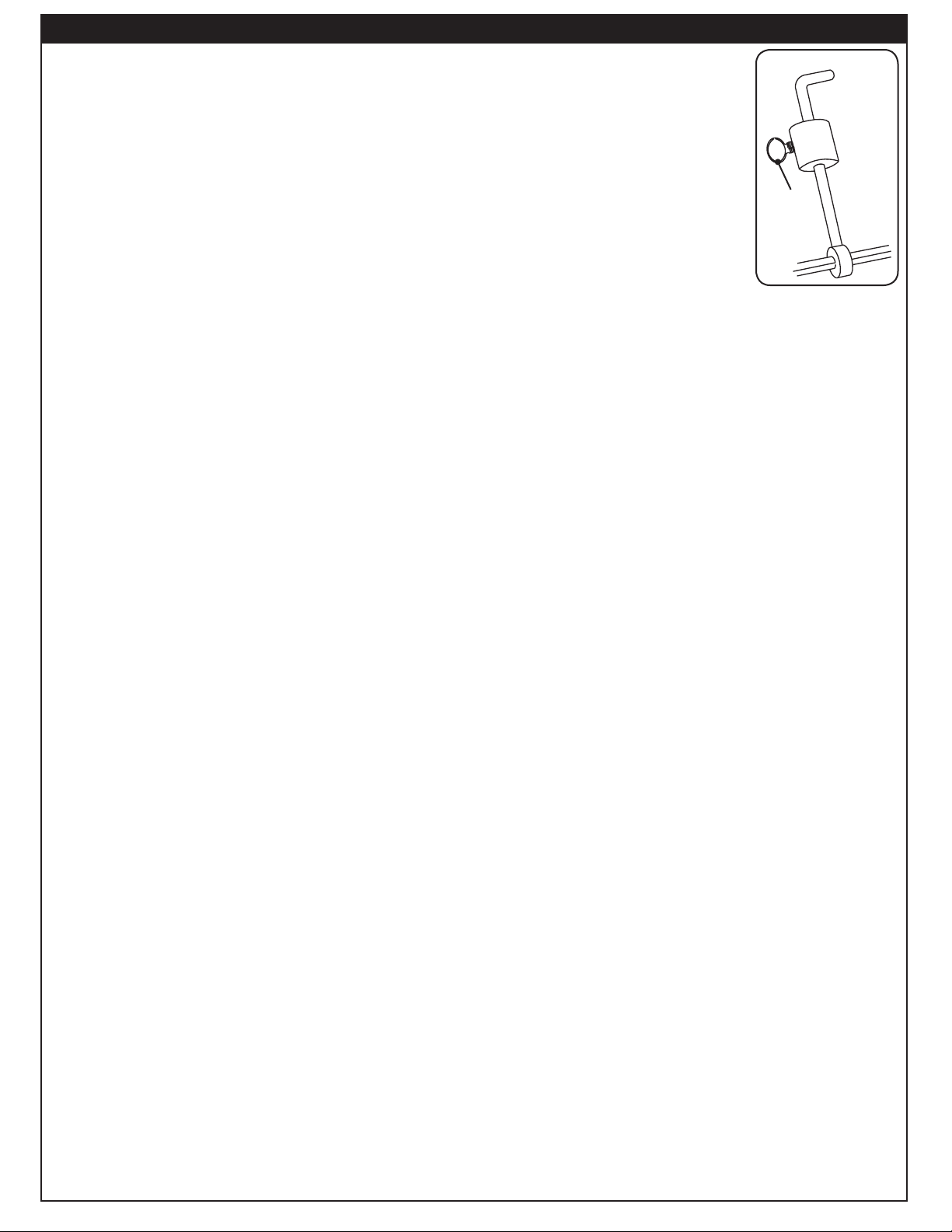
ELECTRONIC LIGHTING
LIGHTING (IGNITION) INSTRUCTIONS
MANUAL LIGHTING
1. Open all lids and remove all covers from the burners
you wish to light.
2. Turn all gas control knobs to their OFF positions.
3. Turn on the gas at its source.
Note: No matter which lighting method you use,
DO NOT turn
on the gas to
more than one
burner at a time.
Adjacent
barbecue
burners will
OFF
TO TURN
TO TURN OFF
Read setting
READ SETTING
here
HERE
OFF
TO TURN ON
TO TURN ON
LIGHT
HI
High to
HIGH TO
light
LIGHT
cross-ignite and
LOW
Fig. 17-1 - Valve control knob
gas flow may
be restricted.
CAUTION: If the burners do not light within 5
seconds, depress the control knob and
turn the knob to OFF. WAIT 5 MINUTES
before repeating step 4. If you smell
gas, follow the instructions on the cover
of this manual. If the burners still do not
light after several attempts, refer to the
instructions for MANUAL LIGHTING.
4. Depress the control knob for the burner to be lit
and turn it to the HI LIGHT position, then press the
ignition button. Once the burner lights, release the
ignition button.
5. Repeat step 4 for each additional burner to be lit.
CAUTION: Always wait 5 minutes for gas to
clear after any unsuccessful lighting
attempt.
1. Follow steps 1 through 4 (left).
2. Insert either a burning long-barrel butane lighter, a
burning long-stem match, or a burning match held
by a wire extension holder (Fig.
the cooking grids to the burner (Fig. 17-3).
For backburners, hold the flame against the
perforated material of the backburner.
For sideburners, hold the fl ame against the burner.
3. While holding the match or lighter fl ame next to
the burner, depress the appropriate burner control
knob and turn it counter-clockwise to the HI LIGHT
position. When the burner lights, remove the lighter
or match.
Fig. 17-2 - Match holder
4. If the burner does not light, IMMEDIATELY depress
the knob and turn the burner control knob to OFF.
WAIT 5 MINUTES before repeating steps 2 through
4 of the MANUAL LIGHTING INSTRUCTIONS.
Note: Barbecues in some installations achieve a
better air/gas mixture and will ignite more
quickly if the burner control knob is fi rst turned
beyond HI LIGHT to LOW for lighting.
17-2) through
FOR PROPANE ONLY
Propane tanks are a equipped with a safety shut-down
device that may cause low or no gas pressure/fl ame
at the burners if operating and lighting instructions
are not followed exactly (See important note in the
TROUBLESHOOTING section for more details.)
ADJUSTING THE FLAME
The knobs on the face of the barbecue control the valves
and adjust the fl ame height. The fi rst labeled position
is OFF, the second HI LIGHT, and the third LOW. In
between the HI LIGHT and LOW labels are mid-point
marks. Flame height can be set anywhere between the
HI LIGHT and LOW settings.
The height of the fl ame with a valve in LOW position
may be further regulated by means of a small adjusting
screw in the center of the valve stem. This screw is
accessible by removing the valve knob, which pulls
straight off the end of the valve stem.
Fig. 17-3 - Manual lighting
REMEMBER: FOR SAFE MANUAL LIGHTING, PLACE A
BURNING MATCH OR BUTANE LIGHTER BESIDE THE
BURNER - THEN TURN ON THE GAS (see Fig. 17-3).
SHUTTING OFF THE GRILL
To shut off the grill, push in each valve control knob and
turn it clockwise to the OFF position.
Always close the valve to the gas supply after each use
of the barbecue.
17
Page 18

ALLUMER DES INSTRUCTIONS (D’ALLUMAGE)
Lisez l’instruction entière avant que s’allumant et suivez ces instructions chaque fois vous lumière le barbecue.
ÉCLAIRAGE ÉLECTRONIQUE
1. Ouvrez tous les couvercles et enlevez toutes les couvertures
des brûleurs que vous souhaitez vous allumer.
2. Arrêtez tous les boutons de commande de gaz à leurs
positions.
3. Allumez le gaz à sa source.
Note: Les barbecues dans quelques installations réalisent
un meilleur mélange d’air/gas et mettront à feu plus
rapidement si le bouton de commande de brûleur
est d’abord tourné au delà de la LUMIÈRE de HI
au BAS pour l’éclairage.
ÉCLAIRAGE MANUEL
Note: Aucune matière que la méthode d’éclairage
vous emploient,
n’allument pas
le gaz à plus d’un
brûleur à la fois.
Les brûleurs
adjacents de
barbecue croix-
OFF
TO TURN
TO TURN OFF
Read setting
READ SETTING
here
HERE
OFF
TO TURN ON
TO TURN ON
LIGHT
HI
High to
HIGH TO
light
LIGHT
mettront à feu
et l’écoulement
LOW
Fig. 18-1 - Valve control knob
de gaz peut être
restreint.
ATTENTION: Si les brûleurs ne s’allument pas dans 5
secondes, enfoncez le bouton de commande
et tournez le bouton à AU LOIN. ATTENDEZ 5
MINUTES avant de répéter l’étape 5. Si vous
sentez le gaz suivez les instructions sur la
couverture de ce manuel. Si les brûleurs ne
s’allument toujours pas après que plusieurs
tentatives, se rapportent aux instructions pour
l’ÉCLAIRAGE MANUEL.
4. Enfoncez le bouton de commande pour que le brûleur
soit allumé et tournez-le dans la position LÉGÈRE de
HI, puis appuyez sur le bouton d’allumage. Une fois que
le brûleur s’allume, libérez le bouton d’allumage.
5. Répétez l’étape 4 pour que chaque brûleur additionnel soit
s’est allumé.
ATTENTION: Attendez toujours 5 minutes le gaz à l’espace
libre après que n’importe quelle tentative non
réussie d’éclairage.
1. Suivez les étapes 1 à 4 (à gauche).
2. Insérez un allumeur brûlant de butane de long-baril, une
allumette brûlante de long-tige, ou une allumette brûlante
tenue par un support de prolongation de fi l (Fig. 18-2)
par les grilles à cuire au brûleur (Fig. 18-3). Pour des
backburners, tenez la fl amme contre le matériel perforé
du brûleur arrière. Pour des sideburners, tenez la fl amme
contre le brûleur.
3. Tout en tenant l’allumette ou la fl amme plus légère à côté
du brûleur, enfoncez le bouton de commande approprié
Fig. 18-2 - Support d’allumette
de brûleur et tournez-le dans le sens contraire des
aiguilles d’une montre dans la position LÉGÈRE de HI.
Quand les lumières de brûleur, enlèvent l’allumeur ou
s’assortissent.
4. Si le brûleur ne s’allume pas, enfoncez immédiatement
le bouton et tournez le bouton de commande de brûleur
à AU LOIN. ATTENDEZ 5 MINUTES avant de répéter
les étapes 2 à 4 des INSTRUCTIONS MANUELLES
d’ÉCLAIRAGE.
POUR LE PROPANE SEULEMENT
Les réservoirs de propane sont équipés d’un dispositif d’arrêt de
sûreté qui peut ne pas causer le bas ou aucun gaz pressure/fl ame
aux brûleurs si le fonctionnement et allumer des instructions ne
sont pas suivis exactement (voir la note importante dans la
section de dépannage pour plus de détails.)
Fig. 18-3 - Éclairage manuel
RAPPELEZ-VOUS: POUR L’ÉCLAIRAGE MANUEL SÛR, PLACEZ
Un ALLUMEUR BRÛLANT D’ALLUMETTE OU De BUTANE PRÈS
Du BRÛLEUR - ALLUMEZ ALORS Le GAZ
(voyez Fig. 18-3).
COUPER LE GRIL
Pour couper le gril, enfoncez chaque bouton de commande
de valve et tournez-le dans le sens des aiguilles d’une montre
à la position de repos.
Fermez toujours la valve à l’offre de gaz après chaque
utilisation du barbecue.
AJUSTEMENT DE LA FLAMME
Les boutons sur le visage du barbecue commandent les
valves et ajustent la taille de fl amme. La première position
marquée est éteinte, la deuxième LUMIÈRE de HI, et le
troisième BAS. Entre la LUMIÈRE de HI et les BASSES
étiquettes sont les marques de point médian. La taille de
fl amme peut être placée n’importe où entre la LUMIÈRE de
HI et les BAS arrangements.
La taille de la fl amme avec une valve en BASSE position
peut être encore réglée à l’aide d’une petite vis de réglage au
centre de la tige de valve. Cette vis est accessible en enlevant
le bouton de valve, qui tire immédiatement l’extrémité de la
tige de valve.
18
Page 19
ROTISSERIE INSTRUCTIONS
USING YOUR BACKBURNER AND
ROTISSERIE
Rotisserie cooking with the backburner is accomplished
without use of the main burners. Follow the steps in the
appropriate sections below to set up and use these
accessories (see PARTS LIST for image).
SET UP
1. Remove the backburner cover (if present) by sliding
it upward off of the backburner.
2. Remove the cooking grids from your barbecue,
if necessary, to obtain maximum clearance for
larger cuts. The fl avor grids may also be removed if
required.
Tip: Aluminum foil or a baking pan may be placed
Tip: Aluminum foil or a baking pan may be placed
3. Attach the rotisserie motor to the rotisserie mounting
3. Attach the rotisserie motor to the barbecue frame by
Note: Make sure the motor is oriented so that no
4. Follow the LIGHTING INSTRUCTIONS to light the
5. Allow the backburner to preheat for approximately
over the main burners, a little forward of
over the main burners to catch excess
center, to catch excess drippings from the
drippings from cooking.
meat.
on the right side of your barbecue by inserting the
inserting the tab of the bracket attached to the motor
four mounting tabs through the four holes in the
into the slot on the right of the barbecue so that the
motor mounting on the right side of the barbecue
spit rod will fi t into the motor drive socket from the left.
and allowing the unit to slide downward and lock into
If left-side spit support is not already in place, insert
place.
it into the tab on the left side of the barbecue at this
time.
rain can fall into the air vents.
backburner.
10 minutes on HI LIGHT setting.
PUTTING THE MEAT ON THE SPIT ROD
1. Slide the meat and spit prongs onto the spit rod so the
meat is centered and balanced as well as possible.
2. Tighten the spit prongs into place so that the meat
remains in a fi xed position on the rod and the meat
rotates with the rod.
Important: The counterbalance, which is included
with your rotisserie kit, should be used
to balance the load on your rotisserie
and prolong the life of your motor. Heavy
unbalanced meats can stress the rotisserie
motor and may cause motor failure.
USING THE COUNTERBALANCE SUPPLIED
WITH YOUR ROTISSERIE
1. Hold the spit rod at each end and lift. Do not grip
the rod. Let the rod rotate so the heavy side of the
meat hangs down naturally.
2. Turn the counterbalance on
the spit so the counterbalance
rod and weight point upward,
or opposite from the heavy
side of the meat. Tighten the
counterbalance rod in the hub
against a fl at surface of the spit
rod to secure (Fig. 19-1).
3. Loosen the thumb screw and
slide the weight along the
counterbalance rod to balance
the meat. Since meats are not
a uniform shape, it may not
be possible to achieve a perfect balance. Properly
balanced meat should not rotate when you hold the
spit rod loosely by the ends.
4. Make sure the counterbalance will not strike the
barbecue frame when the rotisserie is started.
Fig. 19-1
Thumb
screw
RUNNING THE ROTISSERIE
1. Place the pointed end of the spit rod into the motor
drive socket and rest the handle end of the spit rod in
the spit bracket on the right side of the barbecue.
2. Plug in (if necessary) and turn on the rotisserie
motor.
3. Use a standard roasting guide to estimate the length
of time for your meat. A meat thermometer may also
be used to tell when your favorite cuts are cooked
to your liking. When testing temperatures with a
thermometer, turn off the rotisserie motor and turn
the backburner on LOW. This will keep the meat
from over cooking on one side.
Note: When burning properly the backburner fl ames
will be blue with yellow tipping and the grating
will glow red. The fi rst time it is used the
backburner may smoke a little.
Important: Operate your backburner with the oven
closed. This simulates an oven effect and
helps your meat cook faster. Constant
rotation of the spit assures even cooking
and maximum retention of juices.
Note: On large cuts of meat or whole turkeys, it may
be necessary to reduce the heat from your
backburner. Cooking your food at a lower
temperature for a longer period of time will
keep the outer surface from burning while
cooking the interior of your meat. In any case
it is normal for the back burner grating to glow
red when oprating properly.
19
Page 20

REPLACING THE IGNITOR BATTERY
1. Remove the ignitor cover by turning it counter-clockwise.
Important: Do not
attempt to pull or
turn the rubber cap.
2. Remove battery for
replacement. The battery
is re-installed with the
negative (-) end out.
WRONG!!
3. After properly inserting the
battery, replace the ignitor cover
by turning the cap clockwise.
Note: If you have accidently removed the rubber cap,
follow the instructions below to replace it.
1. Pull the rubber
cap and the inner
plastic sleeve
apart.
2. Carefully insert
the rubber cap into
the ignitor cover so
it sits behind inner
lip.
3. Turn the cap
over and slide the
inner plastic sleeve
into the cap.
TROUBLESHOOTING
If you have trouble with the gas barbecue, please use this list to identify the problem. By trying one or more
of the solutions to the possible cause you should be able to solve the problem. If this list does not cover your
present problem or if you have other technical diffi culties with the barbecue, please contact your local barbecue
dealer.
PROBLEM POSSIBLE CAUSE CORRECTION
1) Improper air shutter
1) Adjust air shutters.
adjustment
Ignition system failure
2) Ignition wire disconnected 2) Re-plug wires into generator.
3) Low gas pressure 3) Adjust or replace battery.
4) Dead battery 4) Replace battery.
5) Improper air shutter
5) Adjust air shutters.
adjustment
6) Using propane orifi ce for
6) Change orifi ces.
natural gas
Insuffi cient heat
7) Low gas pressure/fl ame
(natural)
7) Have gas company check
the operating pressure at the
barbecue.
Uneven heating
8) Low gas pressure/fl ame
(propane)
9) Burner ports partially blocked
by debris
10) Small spiders or insects in
burner
8) Reset propane tank safety*:
Shut off all valves including
propane tank and follow lighting
instructions exactly.
9) Remove burners and clean out
ports.
10) Inspect burners for spider
webs or other debris that may
block gas fl ow.
Rotisserie noisy
11) Rotisserie out of balance 11) Adjust counterbalance.
Table 3 - Troubleshooting
*Propane tanks are a equipped with a safety shut-down device that may cause low or no gas/fl ame at the
burners if operating and lighting instructions are not followed exactly. If you suspect the propane tank safety
shut-off is in effect, shut off all burner control valves and the propane tank valve. Then read and follow the
LIGHTING INSTRUCTIONS exactly. Lighting instructions are located in the owner’s manual and printed on
the barbecue’s metal drip tray. If the problem persists continue troubleshooting or contact your local dealer or
R. H. Peterson for assistance.
20
Page 21

ACCESSORIES
USING THE GRILL SCRAPER
The triangular stainless steel piece with serrated edges is
designed to be used as a tool to quickly and easily scrape
food particles and drippings off the grill after barbecuing.
To use it, simply align one of the edges of the scraper
so that the cooking grid
bars fi t into the grooves
in the serrated edge, and
then scrape it along the
length of the cooking grid.
Repeat as needed.
Fig. 21-1
Grill scraper use
USING THE COOKING GRILL LIFTER
Hold the grill lifter by gripping the center section with
the prongs pointing down (use an oven mitt or heavy
glove if the grill is hot). Insert the notched end of the grill
lifter into the grill, in front of the midway point (front to
back- Fig. 21-3), and central (left to right-Fig. 21-4).
Twist the grill lifter (clockwise or counter-clockwise) so
the handle is parallel to the grill rods. This “seats” the
spiked end of the grill lifter between two rods, enabling
you to safely lift the grill out of the barbecue. Lift slowly
and adjust the grill lifter, if necessary, to balance.
DRIP PAN
WARMING RACK
The warming rack (Fig. 21-2) is packed separately
with the barbecue.
To install the warming rack, lift the front of the rack up
slightly and insert the rack hangers into the two holes
in the back of the barbecue above the backburner. Then
lower the front of the rack into a level position to lock the
rack in place.
To remove the warming rack, lift up on the front of the
rack until the rack hangers pull free from their supporting
holes.
Note: For best results, remove the warming rack
before using the rotisserie.
Fig. 21-2 Warming rack in place inside oven
The drip collection system allows you to brush or scrape
excess dried residue inside the barbecue directly into
the drip pan (see PARTS LIST for drip pan location).
To simplify cleanup when using the rotisserie, you may
place a baking pan or foil under the rotisserie to collect
the drippings. Clean the drip pan after each use.
THE FLAVOR GRID(S)
Place each Flavor grid directly on a burner or burner
pair. Center each grid over the burner, oriented as
shown in Fig. 21-6.
Note: This allows heat from the burners to be evenly
distributed throughout the cooking area. The
Flavor grids heat and cool quickly, making the
barbecue very responsive to the changes in
heat from the burners.
Fig. 21-3
Placement of the grill lifter in grill
Fig. 21-4
WOOD-CHIP SMOKER
Your optional backburner is supplied with a woodchip box. The wood-chip box is designed to sit on
top of the backburner assembly over the notch in the
heat defl ector (see Fig. 21-5). This box is designed
to be used when the backburner is in use. To use the
box, just dampen your favorite wood chips and put
them inside; then set it in place. If you wish to refi ll
the wood-chip box when it is hot, you may carefully
handle it using a pair of insulated pliers. You must
be very cautious not to get burned.
Wood-chip (smoker) box
Fig. 21-6
Cover
Air shutter screw
position
Fig. 21-5
21
Page 22

This page intentionally left blank.
22
Page 23

BARBECUE CARE & CLEANING
CARE AND CLEANING
The new Fire Magic barbecue represents the latest
and most advanced technology available. In order
to continue to enjoy the benefi ts of this technology
and to protect your investment, we recommend the
following:
Cover the barbecue with a Fire Magic cover when
not in use.
Clean the unit with a quality stainless steel cleaner
at least once a month (see Fig. 23-1).
Note: In a humid environment, due to the nature
of stainless steel, iron oxide deposits
may appear. Do not be alarmed – these
deposits are removable with stainless steel
cleaner during periodic maintenance.
BARBECUE COVER
Check the burner ports annually for blockage.
The inside of the barbecue may be cleaned
periodically with oven cleaner if desired. Follow the
oven cleaner instructions for proper use.
By following these recommendations you will enjoy
the beauty and power of your barbecue for many
years to come.
Wipe with grain
Fig. 23-1 - Wipe with grain
PROTECTING YOUR BARBECUE
An optional heavy-duty cover will protect the fi nish
on the barbecue and preserve your investment. The
water repellent material will shield the barbecue
from corrosion and oxidation.
To provide a custom fi t, each cover has been cut
and sewn by hand for a particular smoke oven
model. Make sure to give the model number of
the barbecue when ordering a cover from the
manufacturer or your local dealer.
To maintain and protect the barbecue cover,
occasionally wipe the outside with a sponge soaked
in water and a mild household detergent or cleaner,
and rinse with a clean damp cloth.
Important: Allow barbecue to cool before
covering.
Important: Always close the gas supply
shut off valve to the barbecue.
If storing the barbecue for a long
period of time, disconnect the
barbecue from the gas supply
completely.
Always check the burners after long periods
of disuse to look for obstructions that may
hamper performance and safe operation of your
barbecue.
Fig. 23-2
23
Page 24

FIRE MAGIC OUTDOOR GAS BARBECUES LIMITED WARRANTY
PLEASE COMPLETE AND RETURN YOUR REGISTRATION CARD WHICH IS INCLUDED WITH YOUR BARBECUE
LIFETIME WARRANTY - Fire Magic cast stainless steel burners, stainless steel rod cooking grids, and stainless steel housings (including liners, frames,
ovens, and barbecues faces) are warranted for as long as you own your Fire Magic barbecue.
FIFTEEN YEAR WARRANTY - Fire Magic cast brass burners, brass valves, backburner assemblies (except ignition parts), manifold assemblies, and
porcelain hoods and faces are warranted for 15 years from the date of purchase of your Fire Magic barbecue.
THREE YEAR WARRANTY - Fire Magic sideburners and all other Fire Magic barbecue components (except ignition parts) are warranted for 3 years
from the date of purchase of your Fire Magic barbecue.
Fire Magic ignition systems and barbecues accessories are warranted for one year from date of purchase.
PLEASE KEEP A COPY OF YOUR SALES SLIP FOR PROOF OF PURCHASE
This warranty applies to the original purchaser with invoice or proof of purchase and covers Fire Magic products intended for personal, family, or
household usage only. It does not apply to rust, corrosion, oxidation, or discoloration, which may occur due to moisture or overheating, unless the
affected component becomes inoperable. This warranty does not cover parts becoming defective by misuse, accidental damage, improper handling,
and/or installation. It does not cover labor or labor related charges. It specifi cally excludes liability for indirect, incidental or consequential damages.
Some states do not allow the exclusion or limitation of incidental or consequential damages, so the above exclusion may not apply to you. This
warranty gives you specifi ed legal rights and you may have other rights which may vary from state to state.
For additional information regarding this warranty, or information on how to place a warranty claim, contact your authorized Fire Magic dealer.
ROBERT H. PETERSON CO.
Quality Check Date:___________
Orifi ce # (Main):__________
Orifi ce # (Other):__________ Model #: ___________
Leak Test: ___________ Serial #: ___________
Burn Test: ___________ Air Shutter: ___________
Gas Type: NAT. / PROPANE Inspector: ___________
Robert H. Peterson Co. • 14724 East Proctor Ave. • City of Industry, CA 91746
24
 Loading...