

Page 1
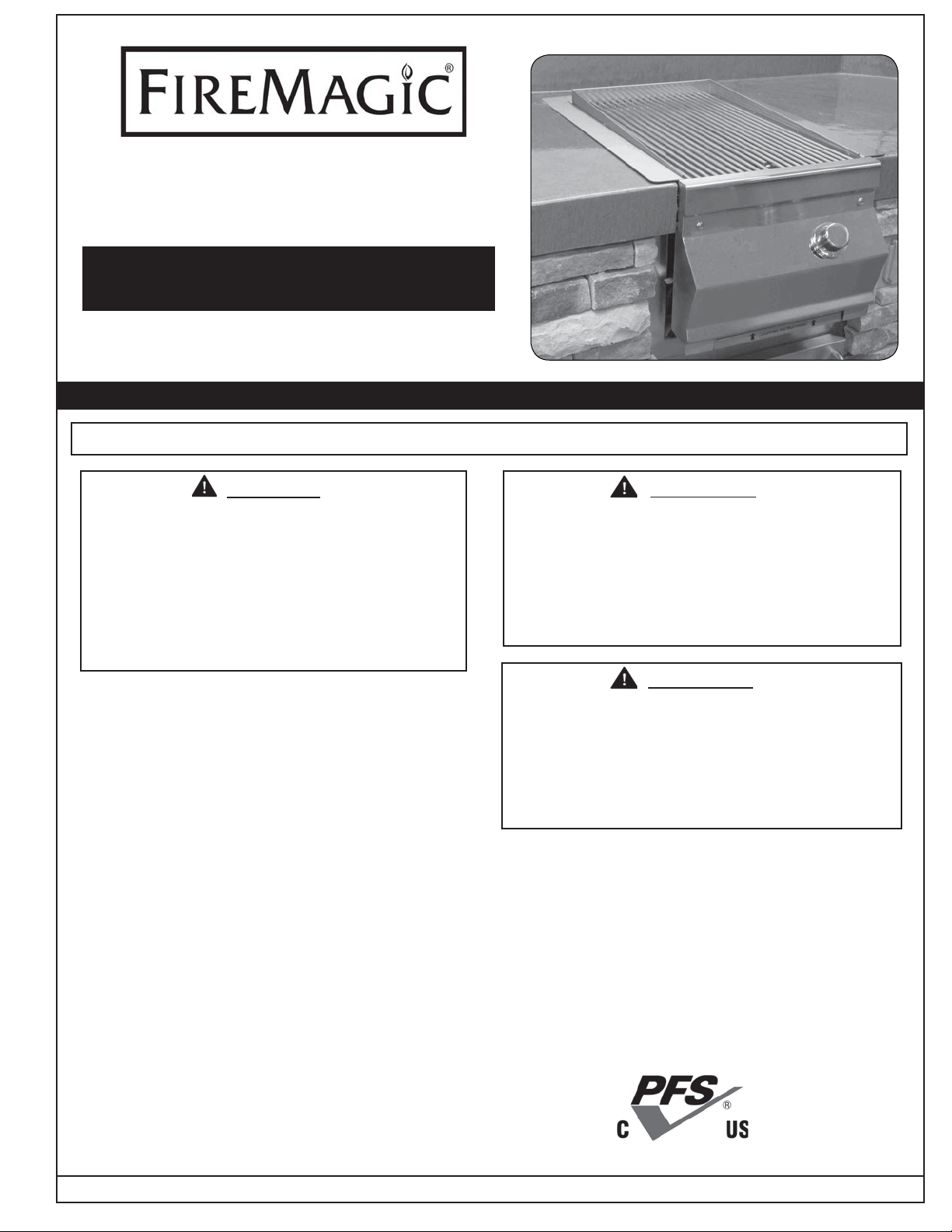
SEARING STATION BUILT-IN
3287-1(P)
INSTALLATION AND OPERATING
INSTRUCTIONS
INSTALLER: Leave these instructions with consumer.
CONSUMER: Retain for future reference.
SAFETY WARNINGS & CODES
IMPORTANT: READ THESE INSTRUCTIONS CAREFULLY BEFORE STARTING INSTALLATION OR USE.
DANGER
IF YOU SMELL GAS:
1. Shut off the gas to the appliance.
2. Extinguish any open fl ame.
3. Open lid if equipped.
4. If odor continues, keep away from the
appliance and immediately call your gas
supplier or fi re department.
CODE AND SUPPLY REQUIREMENTS: This
unit must be installed in accordance with local
codes and ordinances, or, in the absence of local
codes, with either the latest National Fuel Gas
Code (ANSI Z223.1/NFPA 54), or Natural Gas
and Propane Storage and Handling Installation
Code (CSA-B149.1).
This appliance and its individual shutoff valves
must be disconnected from the gas-supply piping
system when testing the system at pressures in
excess of
This appliance must be isolated from the gassupply piping system by closing its individual
manual shutoff valves during any pressure testing
of the gas-supply system at pressures up to and
including
1
/
psig (3.5 kPa).
2
1
/
psig (3.5 kPa).
2
WARNING
1. Do not store or use gasoline or other
fl ammable vapors and liquids in the vicinity
of this or any other appliance.
2. A propane cylinder not connected for use
shall not be stored in the vicinity of this or
any other appliance.
WARNING
Improper installation, adjustment, alteration,
service, or maintenance can cause injury or
property damage. Refer to this manual. For
assistance or additional information, consult a
qualifi ed professional installer, service agency,
or the gas supplier.
All electrical outlets in the vicinity of the unit must
be properly grounded in accordance with local
codes, or, in the absence of local codes, with the
National Electrical Code, ANSI/NFPA 70, or the
Canadian Electrical Code, CSA C22.1, whichever
is applicable.
Keep all electrical-supply cords and fuel-supply
hoses away from any heated surface.
Certifi ed to: ANSI Z21.58-2007
CSA 1.6-2007
Robert H. Peterson Co. • 14724 East Proctor Avenue • City of Industry, CA 91746
Rev 10 - 1401131145
09-41
1
L-C2-200
Page 2

AVERTISSEMENTS ET CODES DE SÛRETÉ
INSTALLATION ET CONSIGNES
D’UTILISATION
BRÛLEUR DESSÉCHANT
INCORPORÉ
3287-1(P)
INSTALLATION ET CONSIGNES
D’UTILISATION
INSTALLATEUR : Laissez ces instructions avec le
consommateur.
CONSOMMATEUR : Maintenez pour la future référence.
IMPORTANT: LISEZ CES INSTRUCTIONS SOIGNEUSEMENT AVANT DE COMMENCER L’INSTALLATION
AVERTISSEMENTS ET CODES DE SÛRETÉ
DANGER:
S’il y a une odeur de gaz:
1. Coupez l’admission de gaz de l’appareil.
2. Éteindre toute fl amme nue.
3. Ouvrir le couvercle.
4. Si l’odeur persiste, gardez loin de l’appareil,
et appelez immédiatement le fournisseur de
gazou le service d’incendie.
CONDITIONS DE CODE ET
D’APPROVISIONNEMENT: Ce grill doit être installé
selon des codes et des ordonnances locaux, ou,
en l’absence des codes locaux, avec l’un ou l’autre
le plus défunt code national de gaz de carburant
(norme ANSI Z223.1/NFPA 54), et stockage de
gaz naturel et de propane et manipulation du code
d’installation (CSA-B149.1).
Cet appareil et ses différents robinets d’isolement
doivent être démontés du système siffl ant d’offre
de gaz en examinant le système aux pressions audessus du
Cet appareil doit être isolé dans le système siffl ant d’offre
de gaz par fermeture ses différents robinets d’isolement
manuels pendant tous les essais sous pression du circuit
Certifi é à la norme: ANSI Z21.58-2007
CSA 1.6-2007
1
/
psig (kPa 3.5).
2
AVERTISSEMENT:
1. Ne pas entreposer ni utiliser de l’essence ni
d’autres vapeurs ou liquides infl ammables
dans le voisinage de l’appareil, ni de proximité
de tout autre appareil.
2. Une bouteille de propane qui nest pas
raccordée en vue de son utilisation, ne doit
pas être entreposée dans le voisinage de
cet appareil ou de tout autre appareil.
AVERTISSEMENT
L’installation inexacte, l’ajustement, le
changement, le service ou l’entretien
peuvent causer des dommages ou des
dégats matériels. Référez-vous à ce
manuel. Pour l’aide ou l’information
additionnelle consultez un installateur
Toutes les sorties électriques à proximité du grill doivent
être correctement fondues selon des codes locaux ou,
en l’absence des codes locaux, avec le code électrique
national, ANSI/NFPA 70, ou le code électrique canadien,
CSA C22.1, qui est jamais applicable.
Gardez tout cordon d’alimentation électrique et tuyau
d’alimentation en combustible a l’écart des surfaces
chauffées.
Robert H. Peterson Co. • 14724 East Proctor Avenue • City of Industry, CA 91746
Rev 10 - 1401131145
09-41
2
L-C2-200
Page 3
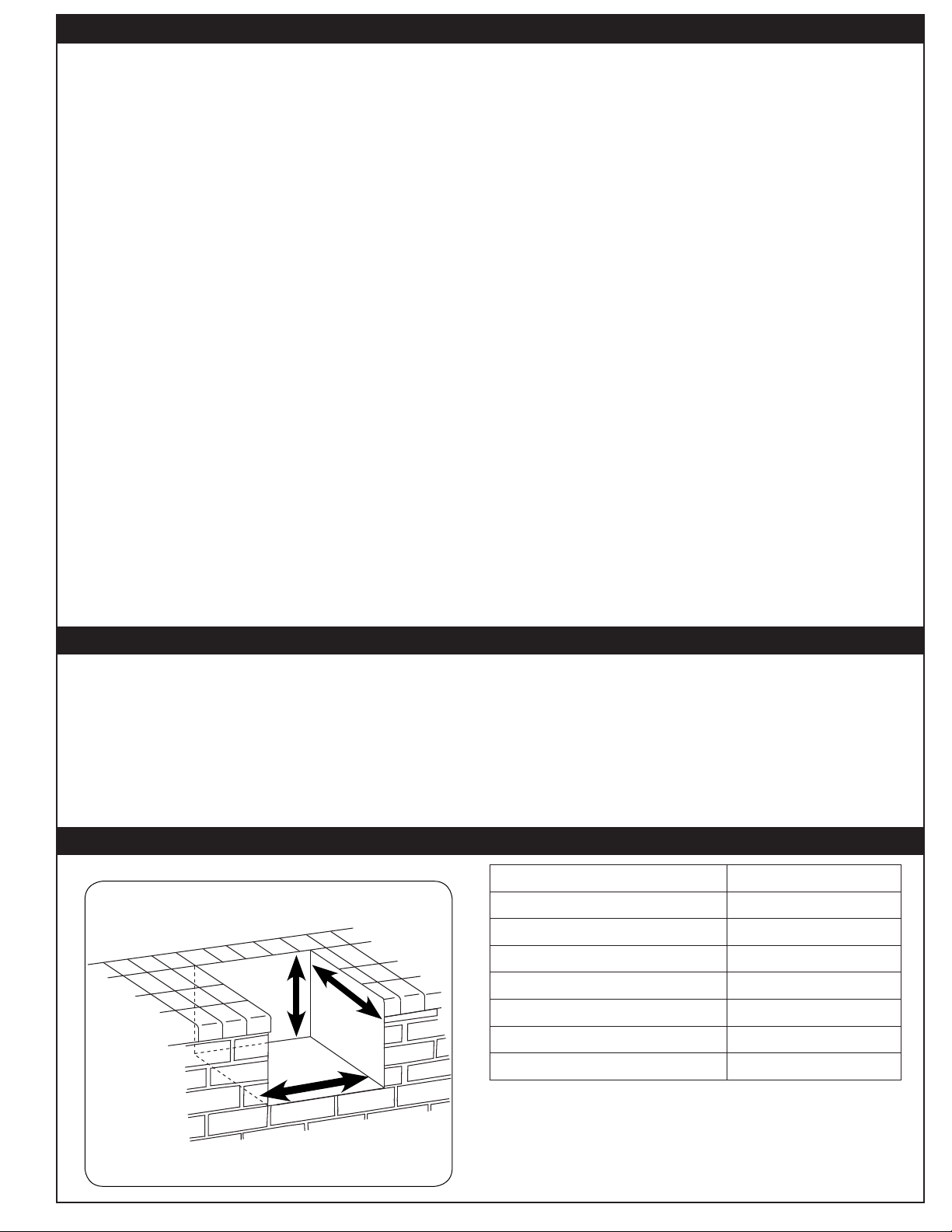
TABLE OF CONTENTS
1 SAFETY WARNINGS & CODES
3 TABLE OF CONTENTS
3 CAUTION
3 PRODUCT DATA TABLE
4 PARTS LIST
5 PLANNING FOR INSTALLATION OF THE SEARING STATION
5 WHERE TO INSTALL THE SEARING STATION
5 ENSURING PROPER COMBUSTION AIR AND COOLING AIRFLOW
5 EXHAUST REMOVAL
6 INSTALLATION
6 GAS-SUPPLY PLUMBING REQUIREMENTS
6 CHECKING FUEL AND ORIFICES
7 CONVERTING THE REGULATOR
7 CONNECTING THE GAS SUPPLY
7 LEAK TESTING
8 NOTES PAGE
9 GENERAL INFORMATION
9 SAFETY TIPS IN USING THE SEARING STATION
9 CARE AND CLEANING
9 FLAME PATTERN
9 SEARING STATION FLAME PATTERN
11 SAFE USE & MAINTENANCE OF PROPANE GAS BOTTLES
13 LIGHTING (IGNITION) INSTRUCTIONS
13 SHUTTING OFF THE UNIT
14 WARRANTY
CAUTION
Do not strike or scrape the ceramic portion of the burner with hard tools, as the material may crack, chip,
or break. Prevent any grease, water, or other foreign material from getting into the ceramic portion of the
burner , especially when cold. Always wait for the burner to heat up to a well-distributed red glow before
placing food on the cooking grid. When a burner is hot, it will vaporize small amounts of grease that drip
on it. Always cover the burner when not in use. Keeping the ceramic portion of the burner free of foreign
substances will allow the gas to circulate and burn over the entire heating surface, allowing for powerful
and even cooking over the life of the burner .
PRODUCT DATA TABLE
Specifi cation Value
Height
Width
Depth
Counter opening height*
Counter opening width* 14"
Counter opening depth* 22-
Main burner
BTU per burner
Natural-gas orifi ce
Propane-gas orifi ce
12"
3
/
4
24,400
#45
#55
"
Rev 10 - 1401131145
Fig. 3-1
Table 1 - Product data table
*Note: If using an insulating liner,
consult liner instructions for
counter cut-out dimensions.
3
L-C2-200
Page 4
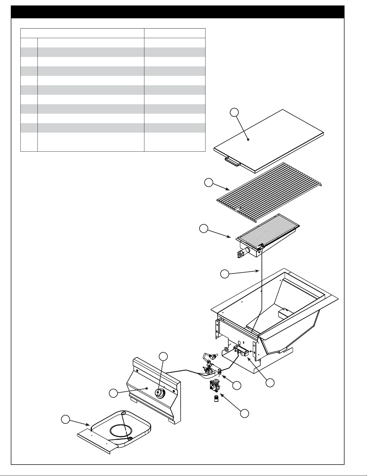
PARTS LIST
Item Description Part No. Qty.
1. Cover 3287-07 1
2. Stainless-steel grid 3551-S 1
3. Burner assembly with ignitor 3049 1
4. Stainless-steel control panel assembly 23287-05 1
5. Valve manifold assembly 3287-22 1
6. Control knob 3016 1
7. Drip tray assembly with match holder 3085 1
8. Regulator PR-4 1
9. Ignitor assembly 3199-35 1
10. Infrared burner wire 3199-71 1
11. Natural gas orifi ce
or Propane gas orifi ce ‡ 3001-55-1 1
‡ Not shown
‡ 3001-45-1 1
1
2
3
10
6
5
4
9
7
Rev 10 - 1401131145
8
4
L-C2-200
Page 5
PLANNING FOR INSTALLATION OF THE SEARING STATION
OFF
HI
LIGHT
LO
W
WHERE TO INSTALL THE SEARING STATION
FOR OUTDOOR USE ONLY
WARNING: The unit must have a minimum of 18" right, left, and back clearance from unprotected
combustible construction such as wood, plastic, or stucco with wood framing. If installing
this unit in a combustible surround, the correct R.H. Peterson insulating liner must be
used.
Do not install this unit under unprotected fl ammable surfaces. Do not install or use this appliance inside
a building, garage, or any other covered or enclosed area. It must not be used in or on recreational
vehicles or boats.
This is a built-in type unit designed to fi t into open-front enclosures. The control panel of the unit is removable
for gas hookup, servicing, and conversion. The control panel must remain removable after the unit is installed.
Installer Note: This unit should be installed so that it can be removed at a later date if factory service is required.
Any protrusion into the searing station enclosure may prevent the unit from sliding into place
(see GAS-SUPPLY PLUMBING REQUIREMENTS
section).
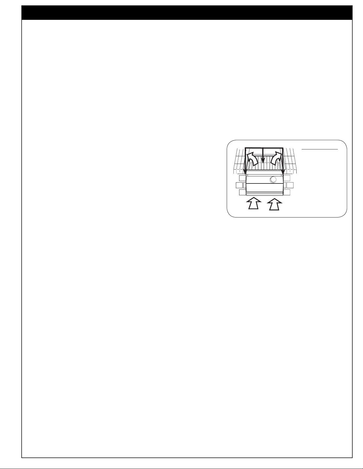
ENSURING PROPER COMBUSTION AIR AND COOLING
AIRFLOW
You must maintain proper airfl ow for the Fire-Magic® Searing Station to
perform as it was designed (Fig. 5-1). If airfl ow is blocked, overheating
and poor combustion will result. Make sure not to block the 1" front
air inlet along the bottom of the control panel or more than 75% of
the support grid surface with pans or griddles.
Hanger
IMPORTANT
The hanger
requires 2" of
countertop on
each side and
back to support
the unit.
Fig. 5-1
Ventilation diagram
Note: The 1" front air space allows access to the drip tray.
EXHAUST REMOVAL
If installed under a patio roof, the cooking grid area should be fully covered by a chimney and exhaust hood.
Rev 10 - 1401131145
5
L-C2-200
Page 6

INSTALLATION
GAS-SUPPLY PLUMBING REQUIREMENTS
1
Rigid
unit. Apply pipe joint compound (resistant to all gasses) to all male pipe fi ttings and tighten all joints securely. Do
not use pipe joint compound to connect fl are fi ttings. The pipe should enter the enclosure either from the bottom
or from any side at least 13" below the countertop.
For natural gas: Normal 7" water column, minimum 5", maximum 10column, minimum 10", maximum 13". A REGULATOR MUST BE PROVIDED AT THE GAS SOURCE FOR USE
WITH PROPANE GAS.
CHECKING FUEL AND ORIFICES
/
" black steel pipe is required to conduct the gas supply into the masonry opening for connection to the
2
Note: Any protrusion into the enclosure higher than 13" below countertop will obstruct the frame
and prevent the unit from dropping into place.
Note: An external valve (with a removable key) in the gas line is recommended for safety.
GAS-SUPPLY AND MANIFOLD PRESSURES
1
/
". For propane gas: Normal 11" water
2
The Fire Magic® Searing Station is equipped with orifi ces for natural
gas unless otherwise indicated. For propane gas, smaller orifi ces
must be installed to avoid hazardous overheating. (Please refer to
Table 1 for the correct orifi ce size.) Check the orifi ce size by following
the instructions below. The drill size is stamped on the orifi ce. If the
number is not visible, you may have to remove the orifi ce (as detailed
below) to read the number stamped on the side of the orifi ce.
When converting the unit, follow the steps below:
1. Remove the Searing Station lid and lift off the cooking grid.
2. Remove the control knob and screws fi rst, and then carefully
lift away the control panel. This allows access to the regulator
(see next page).
Important: Prior to fully removing the control panel, you must
disconnect the battery holder assembly wires that are
located behind the control panel.
3. Pull the wire from the bottom of the electrode attached to the
burner (Fig. 6-1) and carefully lift the burner up, allowing the
tabs to clear the slots in the rear burner rest. Pull the gassupply tube away from the orifi ce (see Fig. 5-2) located inside
the circular opening in the front fi rewall of the unit.
3
/
4. Using a
" socket, remove the orifi ce from the orifi ce holder
8
(see Fig. 6-3) and check the number stamped on the face.
Fig. 6-1
Remove
connector
Fig. 6-2
Orifi ce
5. If an orifi ce change is necessary, replace the orifi ce with the
correct-sized one.
6. Replace the gas-supply tube over the orifi ce, aligning the
burner into the rear burner rest. Re attach the electrode wire.
Note: The regulator and gas connection elbow are located
behind the control panel. For conversion / gas hook
up; see the CONVERTING THE REGULATOR and/or
CONNECTING THE GAS SUPPLY sections before
replacing the control panel.
7 . Replace the control panel, being sure to reconnect the battery
holder assembly wires. Replace the control knob, cooking
grid and lid.
Rev 10 - 1401131145
6
Fig. 6-3
Orifi ce is located
at the end of the
valve
Firewall removed for clarity.
L-C2-200
Page 7
INSTALLATION (Cont.)
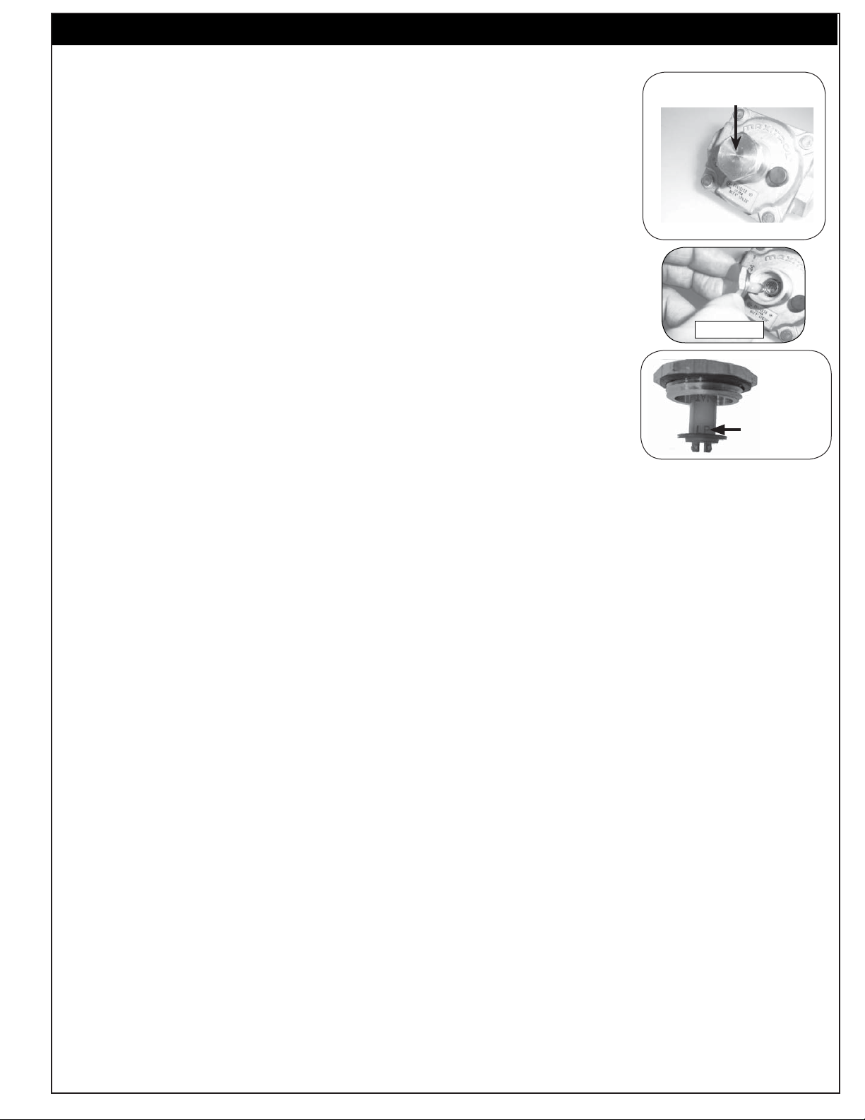
CONVERTING THE REGULATOR
1. Unscrew and remove the cap from the regulator, extracting the converter (Fig.
7-1).
2. Remove the converter (the plastic stalk) by carefully pulling it away from the
center of the cap (it will snap out of its seating); see Fig. 7-2.
3. Turn the converter around and replace it carefully into the center of the cap
(it will snap into place). Check that you can read (at the bottom of the stalk)
the gas type the unit is set to use (Fig. 7-3).
4. Replace the unit into the regulator and screw down until snug. Do not over-
tighten.
CONNECTING THE GAS SUPPLY
1
1. The burner manifold has a
/
" male fl are fi tting gas inlet elbow. A
2
fl are fi tting connector nut is required to hook the gas supply to the burner.
1
/
2
Regulator
Note the cap on top
Fig. 7-1
" female
Fig. 7-2
2 . Use a stainless-steel fl ex connector to bring the gas supply from the gas-line
1
stub or propane-gas tank to the Searing Station manifold. A
/
" x 24" or 36"
2
Fig. 7-3
fl ex connector is suitable for most installations.
CAUTION: Use only a C.S.A.-listed stainless-steel fl ex connector. Do not
use a rubber hose or plastic hose within the enclosure for the
Read gas
type here
Searing Station; it will leak, resulting in an explosion and/or
serious injury.
3. Be sure the gas supply is off. Connect the pipe adapter fi tting supplied with the fl ex connector to the gas-
supply stub. Use pipe joint compound that is resistant to all gasses on the pipe fi tting. Tighten the fi tting
to the gas supply and connector fl are nut securely.
Note: Pipe joint compound should not be used on fl are fi tting connections.
4. Connect the fl ex connector fl are nut to the Searing Station manifold elbow fl are fi tting. Be sure to tighten
securely. Use a second wrench to support the manifold to avoid damaging the manifold.
5. Slide the unit into the enclosure and replace the control panel.
LEAK TESTING
Carefully turn on the gas supply and leak test at all connections with a soapy water solution (equal parts
liquid detergent and water). If bubbles appear, a leak is present. Turn off gas and tighten connections, turn
Rev 10 - 1401131145
7
L-C2-200
Page 8

NOTES PAGE
Please use this page to record any information about your unit that you may want to have at hand.
Rev 10 - 1401131145
8
L-C2-200
Page 9

GENERAL INFORMATION
SAFETY TIPS IN USING THE SEARING STATION
Each time you use the Searing Station, ensure that:
1. The area around the unit is clear and free from fl ammable vapors, liquids, and other combustible materials.
2. There is no blockage of airfl ow around the burner .
3. When using propane gas, ensure that:
a. The special ventilation openings in the enclosure are kept free and clear of debris.
b. If connected to a propane cylinder, inspect the rubber hose attached to the regulator before each use.
c. Propane cylinder, regulator, and hose are installed in a location not subject to heating above 125°F (51° C).
4. Flame is burning evenly and steadily across the burner (mostly blue with yellow tipping).
Important: Do not operate the Searing Station with the cover closed.
CARE AND CLEANING
For cleaning purposes; always leave your burner on (after cooking) for an additional 5 minutes, to allow
for a burnoff period. This is important to keep your burner clean and operating properly.
As the burner is self cleaning (at full temperature); avoid the use of cleaner or abrasives.
CAUTION: Never use acid chemicals or abrasive pads to clean porcelain or aluminum surfaces.
FLAME PATTERN
SEARING STATION FLAME PATTERN
A layer of fl ame may just be visible above the ceramic grid of the searing station burner especially around
the edges. The fl ame will initially appear mostly blue with perhaps a few yellow fl ashes. Soon the red glow
of the ceramic will be the primarily visible color of the burner top. Though there may be small areas of
lesser or greater intensity, the overall red color will become fairly even after about three to fi ve minutes.
Rev 10 - 1401131145
9
L-C2-200
Page 10

U
L
UTILISATION SÛRE ET ENTRETIEN DES CYLINDRES DE GAZ DE PROPANE
IMPORTANT POUR VOTRE SÛRETÉ
LISEZ ET SUIVEZ TOUS LES AVERTISSEMENTS ÉQUIPÉS DE VOTRE CYLINDRE DE GAZ DE PROPANE.
En actionnant cet appareil avec un cylindre de gaz de propane ON DOIT observer ces instructions et avertissements.
LE MANQUE DE FAIRE AINSI PEUT AVOIR COMME CONSÉQUENCE UNE INCENDIE OU UNE EXPLOSION SÉRIEUSE.
CYLINDRE ET CONDITIONS ET
CARACTÉRISTIQUES DE CONNECTEUR
a. Des cylindres et les valves de gaz de propane doivent être
maintenus en bon état et doivent être remplacés s’il y a
des dommages évidents au cylindre ou à la valve.
b. Ce gril, une fois utilisé avec un cylindre, devrait être relié à
un gallon de la norme 5 (20lb.) cylindre de gaz de propane
équipé d’un OPD (remplissez au-dessus du niveau le
dispositif d’empêchement). L’OPD a été exigé sur tous les
cylindres vendus depuis octobre 1.1998 pour empêcher le
remplissage excessif.
c. Les dimensions de cylindre devraient être approximativement
12"(30.5cm) de diamètre et 18" (45.7cm) hauts. Des
cylindres doivent être construits et marqués selon les
caractéristiques pour des cylindres de gaz de propane du
département des ETATS-UNIS du transport (D.O.T.) ou
le niveau national du Canada, du CAN/CSA-B339, des
cylindres, des sphères et des tubes pour le transport des
marchandises dangereuses.
d. Le cylindre doit inclure un collier pour protéger la valve
de cylindre et le circuit d’alimentation de cylindre doit être
assuré le retrait de vapeur.
e. Le montage du régulateur de pression et le fl exible (Fig. 10-1)
e. Le régulateur de pression et l’ensemble de tuyau utilisé
fourni avec cet appareil au gaz en plein air (modèles au
doivent assortir les spécifi cations pour le type I par ANSI
propane seulement) doit être utilisé. Assemblées d'origine et
Z 21.58-2005/CGA 1.6-2005 (voir la fi gue. 10-1).
régulateur de pression et le tuyau de remplacement doivent
être ceux spécifi és par le fabricant pour le raccordement d'un
dispositif de cylindre de liaison identifi ée comme de type I par
le 21.58-2005/CGA ANSI Z 1.6 à 2005 (voir liste des pièces
pour les informations de commande).
f. La valve de cylindre de gaz de propane doit être équipée
d’un dispositif d’accouplement de raccordement de
cylindre, décrit comme type I dans la norme défi nie dans le
e. de paragraphe ci-dessus. Ce dispositif est généralement
décrit comme coupleur rapide de fi l de point culminant.
g. Si votre cylindre de gaz de propane vient avec une prise
de la poussière, placez le bouchon anti-poussière sur la
sortie de valve de cylindre toutes les fois que le cylindre
n’est pas en service.
OPÉRATION DE COUPLEUR RAPIDE
Pour relier le regulator/hose à l’ajustage de précision de
valve de cylindre de gaz de propane: Serrez l’écrou de main
sur le régulateur au-dessus de l’ajustage de précision de fi l
de point culminant sur la valve de cylindre. Tournez l’écrou de
CONDITIONS DE CLÔTURE
POUR VOTRE SÉCURITÉ, vous devez fournir les ouvertures énumérées ci-dessous pour le drainage, l'air de
remplacement, et une ventilation transversale d'une zone de stockage exposés à une fuite possible des raccordements
de gaz, l'unité, ou de bouteilles de propane.
Un côté de l'enceinte peut être complètement ouvert sur l'extérieur, ou 4 ouvertures de ventilation doivent être créés:
Deux des ouvertures doivent être au niveau robinet de la bouteille (environ 16 "au-dessus du sol) et sur des parois
opposées de l'enceinte. 2 ouvertures plus doit être au niveau du sol (env. 5 "au-dessus du sol) et sur les côtés opposés
de l'enceinte. Chaque ouverture doit avoir un minimum de 10 pouces carrés de surface libre. Pour parvenir à la bonne
ventilation, vous pouvez percer une série de trous, omettez le coulis de joints de maçonnerie, ou de remplacer une
brique avec un écran de toile métallique. Si le plancher de l'armoire est soulevée et l'espace situé sous le caisson est
ouvert vers l'extérieur, les ouvertures d'aération inférieures peuvent être dans le sol.
Consultez votre fournisseur de gaz pour les besoins de ventilation et de régulateur lors de la connexion à une
alimentation en propane des ménages.
main dans le sens des aiguilles d’une montre pour engager les
fi ls et pour serrer jusqu’à ce que douillettement. L’utilisation des
pinces ou de la clé ne devrait pas être nécessaire. Seulement
le propane marqué par cylindres doit être employé.
Pour débrancher: Tournez l’écrou de main dans le sens
contraire des aiguilles d’une montre jusqu’à isolé (fi g. 10-1).
Important: Avant d’employer le gril, et ensuite chaque
fois que le cylindre est enlevé et rattaché,
examinez tous les raccordements pour déceler
les fuites. Arrêtez les valves de gril et ouvrez
la valve principale de cylindre, puis vérifi ez
les raccordements avec de l’eau savonneux.
Réparez toutes les fuites avant d’allumer le gril.
ATTENTION: Tournez toujours la valve principale de cylindre
de propane au loin après chaque utilisation,
et avant de déplacer le gril et le cylindre, ou
débrancher l’accouplement. Cette valve doit
rester fermée et le cylindre a débranché alors
que l’appareil n’est pas en service, quoique
l’écoulement de gaz soit arrêté par un dispositif
de sûreté quand le coupleur est débranché.
Inspectez soigneusement l’ensemble de tuyau chaque fois
avant que le gaz soit allumé. Un tuyau criqué ou frangé devrait
être remplacé immédiatement.
Si l'appareil est stocké à l'intérieur, le cylindre doit être disconnected
et a enlevé. Des cylindres Disconnected doivent être stockés
dehors, hors de la portée des enfants, avec les prises de valve
fi letées étroitement installées, et ne doivent pas être stockés dans
un bâtiment, le garage, ou n'importe quel autre secteur inclus.
POUR VOTRE SÛRETÉ
a. Ne stockez pas un cylindre de gaz disponible de propane
dessous ou ne vous approchez pas de cet appareil.
b. Ne remplissez jamais cylindre au delà de 80 pour cent de
plein.
c. SI L’INFORMATION DANS “A” ET “B” N’EST PAS SUIVIE
EXACTEMENT, UN FEU CAUSANT LA MORT OU DES
DOMMAGES SÉRIEUX PEUT SE PRODUIRE.
Fig. 10-1 type coupleur rapide de fi l de point culminant d’I
Volant de commande
QCC
Type 1
Valve
Valve
de
décompression
1
Ajustage de précision
en laiton de fi l de
point culminant
4
Indicateur
de niveau
de liquide
(facultatif)
3
2
Écrou de main avec le
fi l de point culminant.
Régulateur
Passage
Tuy au
10
Page 11

U
L
SAFE USE & MAINTENANCE OF PROPANE GAS CYLINDERS
IMPORTANT FOR YOUR SAFETY
READ AND FOLLOW ALL WARNINGS PROVIDED WITH THE PROPANE-GAS CYLINDER.
When operating this appliance with a propane-gas cylinder, these instructions and warnings MUST be observed.
FAILURE TO DO SO MAY RESULT IN A SERIOUS FIRE OR EXPLOSION.
CYLINDER/CONNECTOR REQUIREMENTS
a. Propane-gas cylinders, valves, and hoses must be
maintained in good condition and must be replaced if
there is visible damage to either the cylinder or valve. If the
hose is cut or shows excessive abrasion or wear, it must
be replaced before using the gas appliance (see e.).
b. This unit, when used with a cylinder, should be connected
to a standard 5-gallon (20 lb.) propane-gas cylinder
equipped with an OPD (Overfi ll Prevention Device).
The OPD has been required on all cylinders sold since
October 1,1998, to prevent overfi lling.
c. Cylinder dimensions should be approximately 12" (30.5
cm) in diameter and 18" (45.7 cm) high. Cylinders must
be constructed and marked in accordance with the
Specifi cations for Propane Gas Cylinders of the U.S.
Department of Transportation (D.O.T.) or the National
Standard of Canada, CAN/CSA-B339, Cylinders,
Spheres, and Tubes for Transportation of Dangerous
Goods.
d. The cylinder used must include a collar to protect the
cylinder valve, and the cylinder supply system must be
arranged for vapor withdrawal.
e. The pressure regulator and hose assembly used must
e. The pressure regulator and hose assembly (Fig. 11-1)
match the specifi cation for Type I by ANSI Z 21.58-2005/
supplied with this outdoor gas appliance (L.P. models
CGA 1.6-2005 (see Fig. 11-1).
only) must be used. Original and replacement pressure
regulator and hose assemblies must be those specifi ed
by the manufacturer for connection with a cylinder
connecting device identifi ed as Type I by the ANSI Z
21.58-2005/CGA 1.6-2005 (see PARTS LIST for ordering
information).
f. The propane-gas cylinder valve must be equipped with a
cylinder connection coupling device, described as Type I
in the standard defi ned in paragraph e. above. This device
is commonly described as an Acme thread quick coupler.
g. If the propane-gas cylinder comes with a dust plug, place
the dust cap on the cylinder valve outlet whenever the
cylinder is not in use.
QUICK COUPLER OPERATION
To connect the regulator/hose assembly to the propanegas cylinder valve fi tting: Press the hand nut on the regulator
over the Acme thread fi tting on the cylinder valve. Turn the hand
nut clockwise to engage the threads and tighten until snug.
ENCLOSURE REQUIREMENTS
The use of pliers or a wrench should not be necessary. Only
cylinders marked “propane” may be used.
To disconnect: Turn the hand nut counterclockwise until
detached (Fig. 11-1).
Important: Before using the unit, and after each time the
cylinder is removed and reattached, check
the hose for wear (see a.) and check all
connections for leaks. Turn off the unit valves
and open the main cylinder valve, then check
connections with soapy water. Repair any
leaks before lighting the unit.
CAUTION: Always turn the propane cylinder main valve
off after each use, and before moving the unit
and cylinder or disconnecting the coupling.
This valve must remain closed and the
cylinder disconnected while the appliance
is not in use, even though the gas fl ow is
stopped by a safety feature when the coupler
is disconnected.
Carefully inspect the hose assembly each time before the
gas is turned on. A cracked or frayed hose should be replaced
immediately.
If the appliance is stored indoors, the cylinder must be
disconnected and removed. Disconnected
cylinders must be
stored outdoors, out of the reach of children, with threaded
valve plugs tightly installed, and must not be stored in a
building, garage, or any other enclosed area.
FOR YOUR SAFETY
a. DO NOT store a spare propane-gas cylinder under or
near this appliance.
b. NEVER fi ll the cylinder beyond 80-percent full.
c. IF THE INFORMATION IN a. AND b. IS NOT FOLLOWED
EXACTLY, A FIRE CAUSING DEATH OR SERIOUS
INJURY MAY OCCUR.
Fig. 11-1 Type I Acme thread quick coupler
QCC
Type 1
valve
Pressure
relief
valve
Hand wheel
Brass Acme
thread fi tting
Liquid level
indicator
(optional)
Hand nut with Acme
thread
Regulator
Vent
Hose
FOR YOUR SAFETY, you must provide the openings listed below for drainage, replacement air, and cross-ventilation
of any storage area exposed to possible leakage from gas connections, the unit, or propane cylinders.
One side of the enclosure can be left completely open to the outside, OR 4 ventilation openings must be created:
Two of the openings are to be at the cylinder valve level (approx. 16” above the fl oor) and on opposite walls of the
enclosure. 2 more openings must be at the fl oor level (approx. 5” above the fl oor) and on opposite sides of the
enclosure. Each opening must have a minimum of 10 sq. in. of free area. To achieve the proper ventilation, you
may drill a series of holes, omit the grout from masonry joints, or replace a brick with a hardware cloth screen. If
the fl oor in the cabinet is raised and the space beneath the cabinet is open to the outside, the lower ventilation
openings may be in the fl oor.
Consult your gas supplier for ventilation and regulator requirements when connecting to a household propane supply.
11
Page 12

ALLUMAGE DES INSTRUCTIONS (D’ALLUMAGE)
Lisez toutes les instructions avant l’allumage, et suivez ces instructions chaque fois vous lumière le unité.
ÉCLAIRAGE ÉLECTRONIQUE
Note: L’éclairage électronique exige une batterie installée
de 9 volts avec une bonne charge.
1. Ouvrez les couvercles ou enlevez les couvertures des brûleurs
pour être Lit.
2. Tournez tous les boutons de commande de gaz à leurs
positions de repos.
3. Allumez le gaz à sa source.
Lisez l’établissement ici
Read setting
(OUTRE de montrer)
here
TURN OFF
OUTRE DE
TO
Enfoncez
le bouton
pour
tourner
Fig. 12-1 - bouton de commande
OFF
LOW
TO TURN ON
LIGHT
HI
SUR
HIGH to
Utilisation
LIGHT
SALUT
(haute)
à la lumière
4. Diminuez le bouton de commande désiré pendant 5
secondes, puis, et tout en pressant le tour il dans le sens
contraire des aiguilles d’une montre dans la position
LÉGÈRE de HI. Une fois que le brûleur s’allume, libérez
le bouton.
Note: N’ouvrez
pas plus d’une
valve à la fois
pour l’éclairage
électronique ou
manuel.
ÉCLAIRAGE MANUEL
ATTENTION: Attendez toujours cinq (5) minutes le gaz
pour se dégager après que n’importe quelle
tentative non réussie d’éclairage.
1. Suivez les étapes 1 à 3 (à gauche).
2. Insérez un allumeur brûlant de butane de long-baril, une
2. Passez un allumeur brûlant de butane de long-baril ou
allumette brûlante de long-tige, ou une allumette brûlante
une allumette brûlante de long-tige dans la grille à cuire
s’ouvrant au dessus du tube d’éclairage. (Fig. 12-2). Pour
tenue par un support de prolongation de fi l par la grille à
des backburners, tenez la fl amme contre le surface du
cuire s’ouvrant au dessus du brûleur (fi g. 12-2).
backburner. Pour des sideburners, tenez la fl amme contre
3. Tout en tenant l’allumette ou la fl amme plus légère au
le brûleur.
dessus du brûleur, diminuez le bouton de commande
3. Tout en tenant l’allumette ou la flamme plus légère
et tout en pressant le tour il dans le sens contraire des
au dessus du tube d’éclairage ou à côté du brûleur
aiguilles d’une montre dans la position LÉGÈRE de
(sideburner et backburner seulement), diminuez le
HI. Enlevez l’allumeur ou assortissez quand le brûleur
bouton et tout en pressant le tour de commande désirés
s’allume, et libérez le bouton de commande.
il dans le sens contraire des aiguilles d’une montre
dans la position LÉGÈRE de HI. Enlevez l’allumeur ou
4. Si le brûleur ne s’allume pas, enfoncez immédiatement
assortissez quand le brûleur s’allume, et libérez le bouton
le bouton et tournez la valve à AU LOIN. ATTENDEZ
de commande.
CINQ (5) MINUTES avant de répéter les étapes 2 à 4
des instructions manuelles d’éclairage.
4. Si le brûleur ne s’allume pas, enfoncez immédiatement
le bouton et tournez la valve à AU LOIN. ATTENDEZ
CINQ (5) MINUTES avant de répéter les étapes 2 à 4
des instructions manuelles d’éclairage.
ATTENTION : Si un brûleur ne s’allume pas dans cinq
(5) secondes d’allumer le bouton de
commande, enfoncez le bouton et tournezle à la position de repos. ATTENDEZ CINQ
(5) MINUTES avant de répéter l’étape 4. Si
vous sentez le gaz, suivez les instructions
sur la couverture de ce manuel. Si les
brûleurs ne s’allument toujours pas après
que plusieurs tentatives, se rapportent aux
instructions pour l’éclairage manuel.
5. Répétez l’étape 4 pour que chaque brûleur additionnel soit Lit.
REMPLACEMENT DES BATTERIES D’ALLUMEUR
Pour remplacer la batterie de 9V actionnant les allumeurs,
retirez le support de batterie situé sur l’extérieur du panneau
de commande. Enlevez le couvercle. Démontez la batterie
du connecteur et remplacez-la reliant la nouvelle batterie.
Remplacez le couvercle et fermez le tiroir (voir la fi g. le 12- 3).
EN EMPLOYANT UN RÉSERVOIR DE PROPANE PORTATIF
Des réservoirs de propane sont équipés d’un dispositif
d’arrêt de sûreté qui peut ne pas causer le bas ou aucunes
pression de gaz/fl amme aux brûleurs si le fonctionnement
et l’allumage des instructions ne sont pas suivis exactement
(voir la note importante dans la section de dépannage pour
plus de détails.)
Tube
d’éclairage
Plus léger
Fig. 12-2 - Éclairage manuel
Fig. 12-2 - Éclairage manuel
ARRÊT DU UNITÉ
Pour couper le unité, diminuez chaque bouton de commande
de valve et, et tout en pressant tour il dans le sens des
aiguilles d’une montre à la position de repos.
Fermez toujours la valve de la fourniture de gaz après chaque
utilisation du unité.
Fig. 12-3
12
Fig. 12-3
Page 13

LIGHTING (IGNITION) INSTRUCTIONS
Read all instructions before lighting, and follow these instructions each time you light the unit.
ELECTRONIC LIGHTING
Note: Electronic lighting requires an installed 9-volt
battery with a good charge.
1. Open lid(s) or remove cover(s) from burner(s) to be lit.
2. Turn all gas control knob(s) to their OFF position(s).
3. Turn on the gas at its source.
Read setting here
Read setting
(OFF position shown)
TURN OFF
To Turn OFF
TO
Press
knob in
to turn
Fig. 13-1 - Control knob
here
OFF
LOW
To Turn ON
TO TURN ON
LIGHT
HI
HIGH to
Use
LIGHT
HI (high)
to light
4. Depress the desired control knob for 5 seconds,
then, while pressing turn it counterclockwise to the
HI LIGHT position. Once the burner lights, release
the knob.
Note: DO NOT
turn on more
than one valve at
a time for either
electronic or
manual lighting.
MANUAL LIGHTING
CAUTION: Always wait fi ve (5) minutes for gas to
clear after any unsuccessful lighting
attempt.
1. Follow steps 1 through 3 (left).
2. Insert either a burning long-barrel butane lighter or
2. Insert either a burning long-barrel butane lighter, a
a burning long-stem match through the cooking grid
burning long-stem match, or a burning match held
opening to the top of the lighting tube. (Fig. 13-2).
by a wire extension holder through the cooking grid
For backburners, hold the flame
opening to the top of the burner (Fig. 13-2).
against the surface of the backburner.
3. While holding the match or lighter fl ame at the top
For sideburners, hold the fl ame against the burner.
of the burner, depress the control knob and while
3. While holding the match or lighter fl ame at the top
pressing turn it counterclockwise to the HI LIGHT
of the lighting tube or next to the burner (sideburner
position. Remove the lighter or match when the
and backburner only), depress the desired control
burner lights, and release the control knob.
knob and while pressing turn it counterclockwise to
4. If the burner does not light, immediately depress
the HI LIGHT position. Remove the lighter or match
the knob and turn the valve to OFF. WAIT FIVE
when the burner lights, and release the control
(5) MINUTES before repeating steps 2 through 4
knob.
of the MANUAL LIGHTING instructions.
4. If the burner does not light, immediately depress
the knob and turn the valve to OFF. WAIT FIVE
(5) MINUTES before repeating steps 2 through 4
of the MANUAL LIGHTING instructions.
CAUTION: If a burner does not light within fi ve (5)
seconds of turning on the control knob,
depress the knob and turn it to the OFF
position. WAIT FIVE (5) MINUTES
before repeating step 4. If you smell
gas, follow the instructions on the cover
of this manual. If the burners still do not
light after several attempts, refer to the
instructions for manual lighting.
5. Repeat step 4 for each additional burner to be lit.
REPLACING IGNITOR BATTERIES
To replace the 9V battery powering the ignitors, pull out the
battery holder located on the outside of the control panel.
Remove the lid. Disconnect the battery from the connector
and replace it connecting the new battery. Replace the lid
and close the drawer (see Fig. 13-3).
WHEN USING A PORTABLE PROPANE TANK
Propane tanks are equipped with a safety shutdown
device that may cause low or no gas pressure/fl ame
at the burners if operating and lighting instructions
are not followed exactly (See important note in the
TROUBLESHOOTING section for more details.)
Lighting
tube
Lighter
Fig. 13-2 - Manual lighting
Fig. 13-2 - Manual lighting
SHUTTING OFF THE UNIT
To shut off the unit, depress each valve control knob
and, and while pressing turn it clockwise to the OFF
position.
Always close the valve from the gas supply after each
use of the unit.
Fig. 13-3
13
Fig. 13-3
Page 14

WARRANTY
PETERSON FIRE MAGIC GRILLS AND ACCESSORIES
LIMITED WARRANTY
Robert H. Peterson Co. ("RHP") warrants your Fire Magic® grill to be free from defects in material and workmanship.
Fire Magic
your Fire Magic® grill -- LIFETIME. (Except as noted below.)
Fire Magic Choice stainless steel tubular burners are warranted for TWENTY (20) YEARS.
Fire Magic
warranted for FIFTEEN (15) YEARS.
Fire Magic
Fire Magic
charcoal pan, charcoal grid, wood pellet screen, thermometer, and ash tray; which are warranted for ONE (1) YEAR.
Fire Magic
YEARS.
Fire Magic
warranted for ONE (1) YEAR.
This warranty applies to the original purchaser for products which are installed in the United States or Canada and which are operated and maintained
as intended for single family residential usage. This warranty is valid only with proof of purchase, shall commence on the date of purchase, and shall
terminate (both as to original and any replacement products) on the anniversary date of the original purchase of the product stated on the above schedules.
This warranty covers defects in material and workmanship. This warranty does not cover parts which become defective as a result of negligence, misuse,
use not in compliance with the Owner’s Manual/Installation Instructions, accidental damage, improper handling, improper storage, improper installation,
lack of required routine maintenance (as specifi ed in the Owner’s Manual/Installation Instructions), electrical damage, local gas impurities or failure to
protect against combustibles. Product must be installed (and gas must be connected) as specifi ed in the Owner’s Manual/Installation Instructions by
a qualifi ed professional installer. Modifi cations to products which are not specifi cally authorized will void this warranty. Accessories, parts, valves,
remotes, etc. when used must be Peterson products or this warranty is void. Warrantied items will be repaired or replaced at Peterson’s sole discretion.
This warranty does not apply to rust, corrosion, oxidation, or discoloration unless the affected part becomes inoperable.
This warranty does not cover labor or labor related charges, except as provided by separate specifi c written programs from the Peterson Co. All repair
work must be performed by a qualifi ed professional service person and requires prior approval of Peterson.
Peterson may require the defective product or part to be returned to the factory to determine the cause of failure. Peterson will pay freight charges if
the product or part is determined to be defective. This warranty does not cover breakage in shipment from our (Independent) distributor to its customer
if the damage is determined to have occurred during that shipment.
This warranty specifi cally excludes liability for indirect, incidental, or consequential damages. Some states and provinces do not allow the exclusion
or limitation of incidental or consequential damages, so the above exclusion may not apply to you. This warranty gives you specifi ed legal rights, and
you may have other rights that vary from state to state or province.
For additional information regarding this warranty, or to place a warranty claim, contact the R. H. Peterson dealer where the product was purchased.
®
cast stainless-steel burners, stainless-steel rod cooking grids, and stainless-steel housings are warranted for as long as you own
®
cast brass burners, brass valves, inner liners, manifold assemblies, and backburner assemblies (except ignition parts) are
®
Electric Grills, including stainless steel grid, and housings are warranted for TEN (10) YEARS.
®
Infra-red burners, fl avor grids, Charcoal stainless steel grills, and Smokers are warranted for FIVE (5) YEARS; except for the
®
sideburners and all other Fire Magic® grill components (except ignition and electronic parts) are warranted for THREE (3)
®
ignition systems (excluding batteries), electronic components (including lights and thermometers), and grill accessories are
A COPY OF YOUR SALES SLIP FOR PROOF OF PURCHASE IS REQUIRED
TO REGISTER YOUR PRODUCT ONLINE GO TO: WWW.RHPETERSON.COM,
AND CLICK ON PRODUCT REGISTRATION. THANK YOU FOR YOUR PURCHASE.
Quality Check Date:_________________
Burner Orifi ces Nat. L.P. Leak Test: ___________ Model#: ___________________
Main: ____ ____ Burn Test: ___________ Serial#: ___________________
Other: ____ ____ Gas Type:
Robert H. Peterson Co. • 14724 East Proctor Avenue • City of Industry, CA 91746
Nat. / L.P. Air Shutter: ___________________
Inspector: ___________________
14
 Loading...