

Page 1
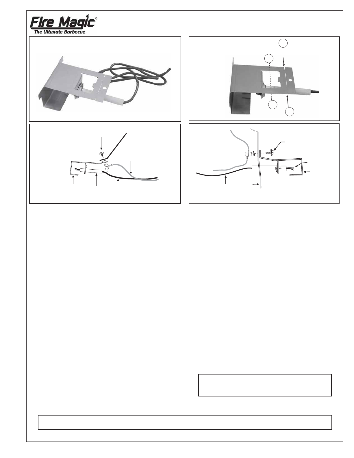
ELECTRODE KIT INSTALLATION INSTRUCTIONS
ELECTRODE
WIRE
MOUNTING
SCREW
(SUPPLIED)
BBQ LINER
COLLECTOR
BOX
ELECTRODE
FOR FIRE MAGIC BARBECUES
MODEL NO. 3199-60
MOUNTING NUT,
WASHER,
& SCREW
COLLECTOR
BOX
ELECTRODE
Figure 2
REPLACING THE ELECTRODE KIT FOR
SLIDE-IN UNITS
(see over for Regal I Drop-In units)
1. Remove the valve knobs from the face or panel.
2. Remove the screws and finish washers securing
the face.
3. Carefully remove the face or top panel.
CAUTION: The spark generator may be attached
to the face or panel. Carefully unplug the wires from
the spark generator before pulling away from the
unit.
4. Remove the nuts and the screw securing the old
electrode kit to the barbecue liner and remove the
old kit.
BBQ INNER LINER
GROUND WIRE
(GREEN)
ELECTRODE WIRE
(BLACK)
A
BEND ALONG
THIS LINE
B
B
Figure 1
BENDING MAY
OCCUR HERE
A
Figure 3
Note: For all setups you will need to bend part of
the collector box upwards along point A (see Figure
1). We recommend you use pliers to start, then use
a flat non-slip surface to bend the metal to the right
angle required, as in Figure 3. The other setup
(Figure 2) may require a smaller bend, as fits the
circumstance. Use the old collector box & bracket
as a reference for the proper bend. When the
collector box is screwed into place, ensure the outer
shoulders rest firmly and squarely on the burners.
Slight bending may occur across point B. This is
normal and allows box to sit in the correct position.
7. Plug the wires into the spark generator (If you have
a 3 plug generator ,green ground wire must go into
the center plug).
8. Replace the face and knobs.
REV A 030405
5. If the old collector box has a mounting bracket which
attaches it to the barbecue liner, remove this along
with the old collector box, then go to step 6.
9. Check unit for spark.
10. Secure the face to frame with original face screws.
6. Attach the new electrode kit and ground (if used) to
the barbecue liner with the adjusting screw , n ut and
washer provided, in the method indicated in either
Figures 2 or 3, whichever matches your barbecue
setup. Ensure the new collector box is fitted in the
We reserve the right to amend product
specifications without prior notice.
same position as the old one.
This manual may not be copied, photocopied, reproduced, translated, or published in any electronic or
machine-readable form in whole or in part without prior written approval of Robert H. Peterson Co.
ROBERT H. PETERSON CO. • 14724 East Proctor Aven ue • City of Industry, CA 91746
1
No. L-C2-10905
Page 2
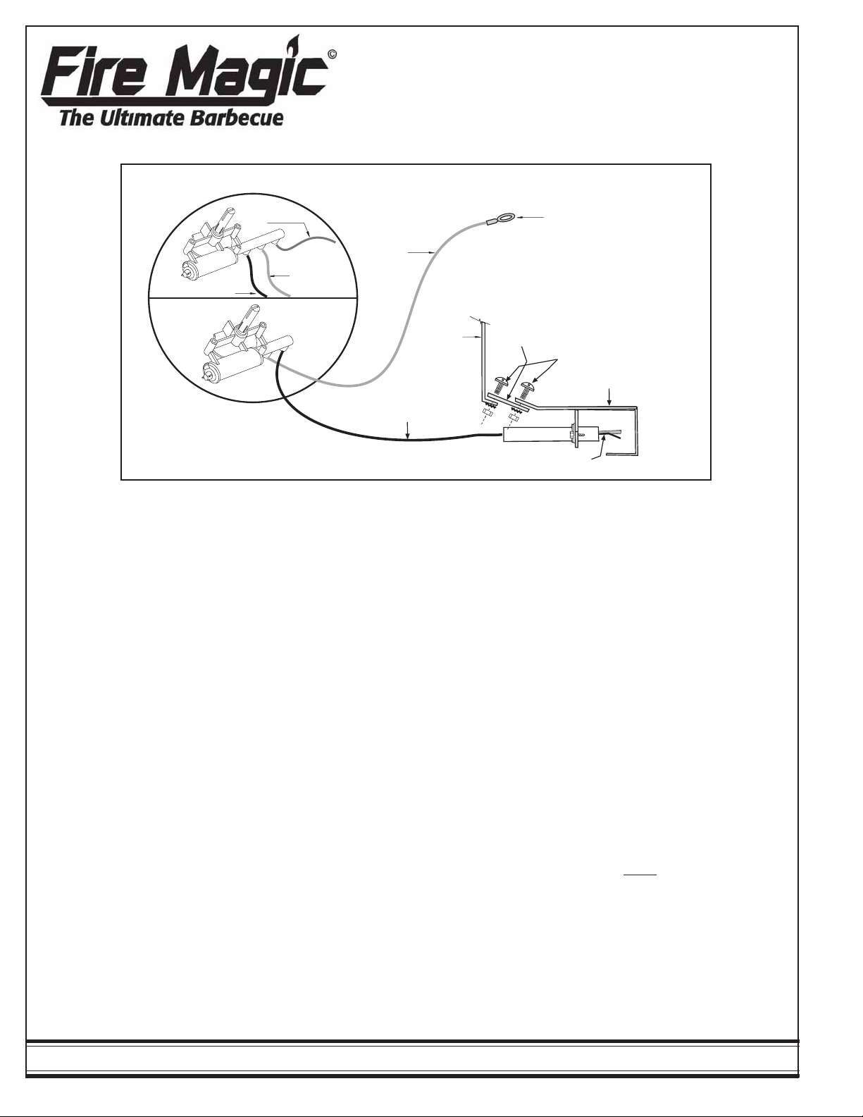
FIRE MAGIC ELECTR ODE REPLACEMENT KIT
FOR REGAL DROP-IN MAIN BARBECUE B URNERS
Note: This kit may include a part or parts not needed for every installation.
To Spark Generator
3 Plug
BBQ
ELECTRODE
WIRE
BACKBURNER
ELECTRODE
WIRE
GROUND
WIRE
GROUND
WIRE
CONNECTS TO BBQ FRAME
OR SIDE WALL OF LINER
2 Plug
ELECTRODE
WIRE
Figure 1
1. Remove the valve knobs from the top (control)
panel.
2. The panel is secured to the barbecue frame by
four spring clips. With the o ven open, lift up firmly
from the inside front left and front right corners of
the panel frame.
3. After the front spring clips release, carefully
remove the panel from the unit.
CAUTION: The spark generator is attached to the
control panel. Carefully unplug the wires from the
spark generator before lifting the panel clear away
from the unit.
4. Remove the screw and nut securing the old
electrode kit to the barbecue liner and remove the
old kit.
Note: The new electrode wire will be easier to
install if the following procedure is followed:
a. Tie one end of the enclosed string to the end
of the old electrode wire that plugged into the
spark generator.
b. Pull the wire, with the string attached, into the
barbecue firebox.
c. Cut the string off the old wire and tie it to the
new electrode wire. Pull the string and plug
end of the new wire from the firebox into the
area below the control panel.
BBQ LINER
MOUNTING
BRACKET
MOUNTING
SCREWS
ELECTRODE
COLLECTOR
BOX
5. Attach the new electrode collector box assembly
to the barbecue liner with the screws and nuts
provided as shown in Figure 1.
Note: A mounting bracket is needed to fasten the
new collector box to the barbecue liner.
6. If the mounting bracket is not attached to the
barbecue liner as illustrated in Figure 1, bend the
old electrode out of the way and remove the
adjusting screw from the mounting bracket at the
top of the old collector box assembly. Attach the
new collector box and electrode to the old mounting
bracket with the adjusting screw (Figure 1).
7. A replacement ground wire is provided with a ring
which can be placed over the front
1
/4” manifold
mounting screw and secured with the extra 1/4” nut
provided.
8. Plug the wires into the spark generator.
IMPORTANT: If your unit has a 3 plug spark
generator, the g round wire
must be plugged into the
middle position. For 2 plug spark generators, the
wires can be plugged into any position.
9. Replace the control panel, pressing down firmly to
snap over the spring clips. Align the control panel
and replace the valve knobs.
ROBERT H. PETERSON CO. • 14724 East Proctor Avenue • City of Industry, CA 91746
2
 Loading...