

Page 1
DELUXE / POWER BURNER /
SEARING STATION
INSULATING LINERS
Model# 3100-51
32(78,87)-51
INSTALLER: Leave these instructions with consumer.
CONSUMER: Retain for future reference.
SPECIFICATIONS
IMPORTANT INFORMATION
Read these instructions and the safety and installation sections
of the appliance owner's manual before liner installation.
The insulating liner comes pre-assembled and ready to install.
FOR YOUR SAFETY, the enclosure must provide openings for
drainage, replacement air, and cross-ventilation of any storage
area exposed to possible leakage from gas connections, the
unit, or propane cylinders.
This liner is only for installation in an enclosure constructed
of combustible materials and a NON-COMBUSTIBLE
countertop.
All additional enclosure requirements, safety guidelines,
and any other requirements found in your appliance owner's
manual MUST BE FOLLOWED.
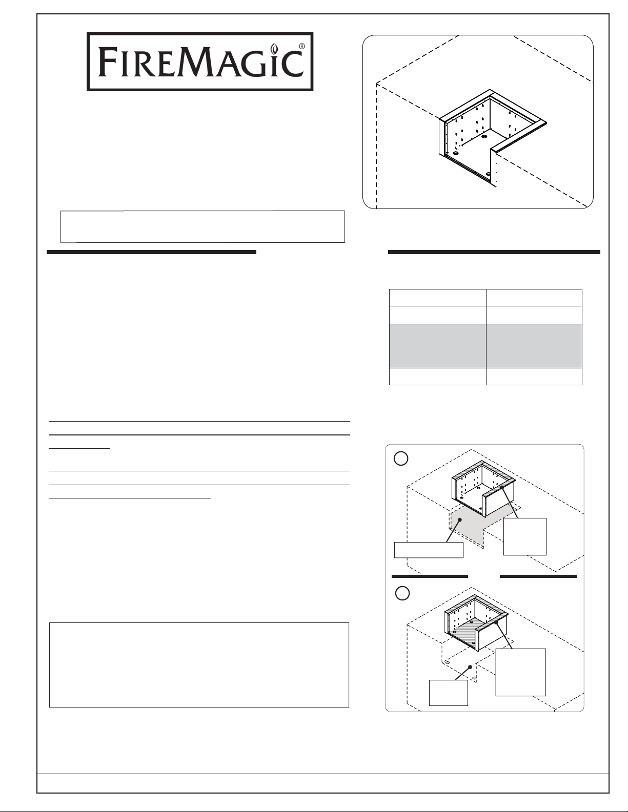
DETERMINE INSTALL METHOD AND PREPARE
CUTOUT
The insulating liner can be hung from the countertop using
the liner hangers (see Fig. 1-1, A), or the liner bottom can sit
directly on a sturdy base with the additional support of the
hangers (see Fig. 1-1, B).
Series Liner Model
Deluxe 3100-51
Power Burner,
Double Searing
Station
Searing Station 3287-51
Table 1 - Models available
A
(Open bottom)
OR
B
3278-51
Use
hangers
only
See your appliance owner's manual for all overall
enclosure requirements.
See sections on following pages regarding cutout
dimensions, and countertop overhang and substrate
considerations. Then proceed to INSTALLATION.
ROBERT H. PETERSON CO. • 14724 East Proctor Avenue • City of Industry, CA 91746
REV 0 - 1502100720
(Use
hangers as
Rest on
base
Fig. 1-1 Determine install method
1
additional
support)
L-C2-465
Page 2
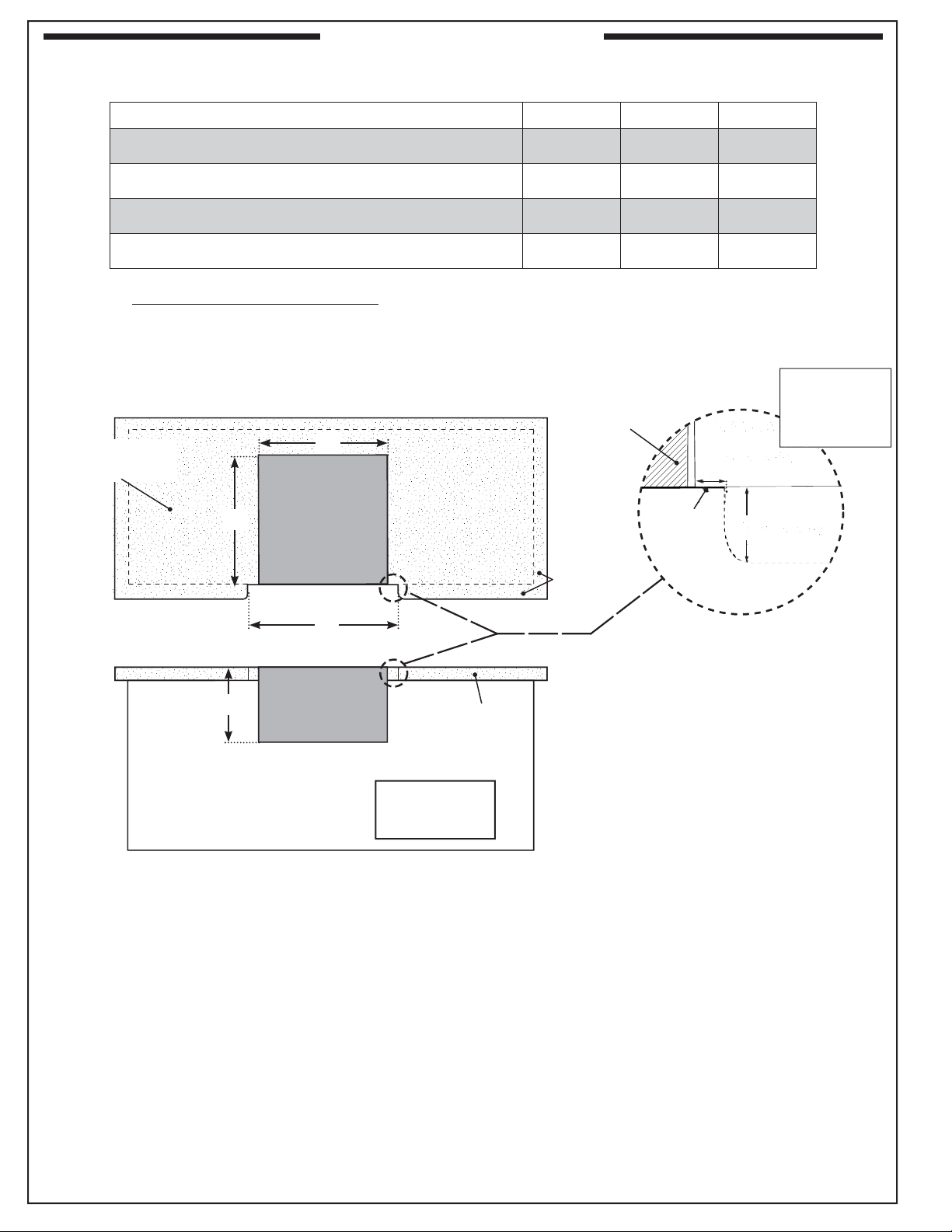
CUTOUT DIMENSIONS
A Countertop to unit bottom cut-out 12 1/4" 12" 11 5/8"
SPECIFICATIONS (cont.)
3100-51 3278-51 3287-51
B Side to side cut-out 28
C Front to back cut-out * 19
D Liner fl ange width cut-out
*
Includes any substrate at front wall of enclosure (in the areas the liner fl anges are to sit fl ush against).
See SUBSTRATE section on next page.
†
Only applicable for enclosures that have countertops with an overhang (see illustration and section below).
Non-combustible
Countertop
TOP VIEW
ENCLOSURE
CUT-OUT
C
DIMENSIONS
1
/8" 22 3/4" 18 1/4"
3
/8" 20 7/8" 24 3/4"
†
B
29 3/8" 24" 19 3/8"
(Liner shown
for clarity)
Countertop
overhang
(Liner
fl ange)
TOP VIEW
(Countertop)
X
Y
(Overhang)
X= D-B÷2
Y= Total
Countertop
Overhang
D
FRONT VIEW
A
See next page
for substrate
considerations
Fig. 2-1
Countertop Overhang
The liner front fl anges are designed to sit fl ush against the enclosure front wall. If the countertop extends beyond the front
wall, creating a countertop overhang, it must be cut fl ush with the front wall for the width of the liner fl anges or a gap will
be created exposing the forward portions of the left and right side liner walls. See illustrations above.
Important: FOR YOUR SAFETY, you must provide openings in the island enclosure for drainage, replacement air, and
cross-ventilation of any storage area exposed to possible leakage from gas connections, the unit, or propane
bottles. See the ENCLOSURE REQUIREMENTS section in appliance owner's for details.
Countertop
overhang
Drawings
not to scale
REV 0 - 1502100720
2
L-C2-465
Page 3

SPECIFICATIONS (cont.)
Substrate
When adding any substrate to the enclosure front wall (including tiles, stone, etc.), consider the following:
Substrate Behind Liner Flange
Substrate + countertop "front to back" cutout
must equate to Dim. C (see previous page)
when the substrate sits fl ush behind the
liner fl anges.
TOP VIEW
(Countertop)
Substrate
(includes tiles,
etc. at front of
enclosure)
Flush
C
Countertop
overhang
(if applicable)
Liner
Liner fl ange
(both sides)
Substrate Alongside Liner Flange
Any additional substrate alongside the liner fl anges does
not need to be considered in Dim. C (see previous page).
TOP VIEW
(Countertop)
Substrate
(includes tiles,
etc. at front of
Flush
C
enclosure)
Countertop
overhang
(if applicable)
Liner
Liner fl ange
(both sides)
Fig. 3-1 Fig. 3-2
INSTALLATION
1. Install the insulating liner as shown in Fig. 3-3.
• If installing on a countertop with an irregular/textured
surface, a bead of silicone sealer rated for 400° or higher
may be needed.
1
• If the liner is being installed using method B, a 1
must be cut through the base (enclosure) to allow for proper
gas installation.
1
If applicable, a second 1
/2" hole must be cut to allow for
proper electrical installation.
ee Fig. 3-3 for hole locations. Use the insulating liner holes
S
as guides. Remove knock-outs as needed.
• Holes exist at the rear of the liner; however, it is recommended
to use the front holes.
2. Install your appliance per your appliance owner's manual.
Important: Do not allow the appliance hanger to come in
contact with the countertop or any combustible
surface (
see Fig. 3-4).
/2" hole
11/2"
hole
(gas)
11/2"
electrical hole
(if applicable)
Fig. 3-3 Install insulating liner
Appliance
hanger rests on
insulating liner
(sides and rear)
REV 0 - 1502100720
Fig. 3-4 Install appliance into liner
3
L-C2-465
Page 4

NOTES PAGE
REV 0 - 1502100720
Please use this page to record any information that you may want to have at hand.
4
L-C2-465
 Loading...