

Page 1
INFRARED BURNER KIT
3
1
INSTRUCTIONS
(HOT SURFACE IGNITION)
Model # 3050
# 3060
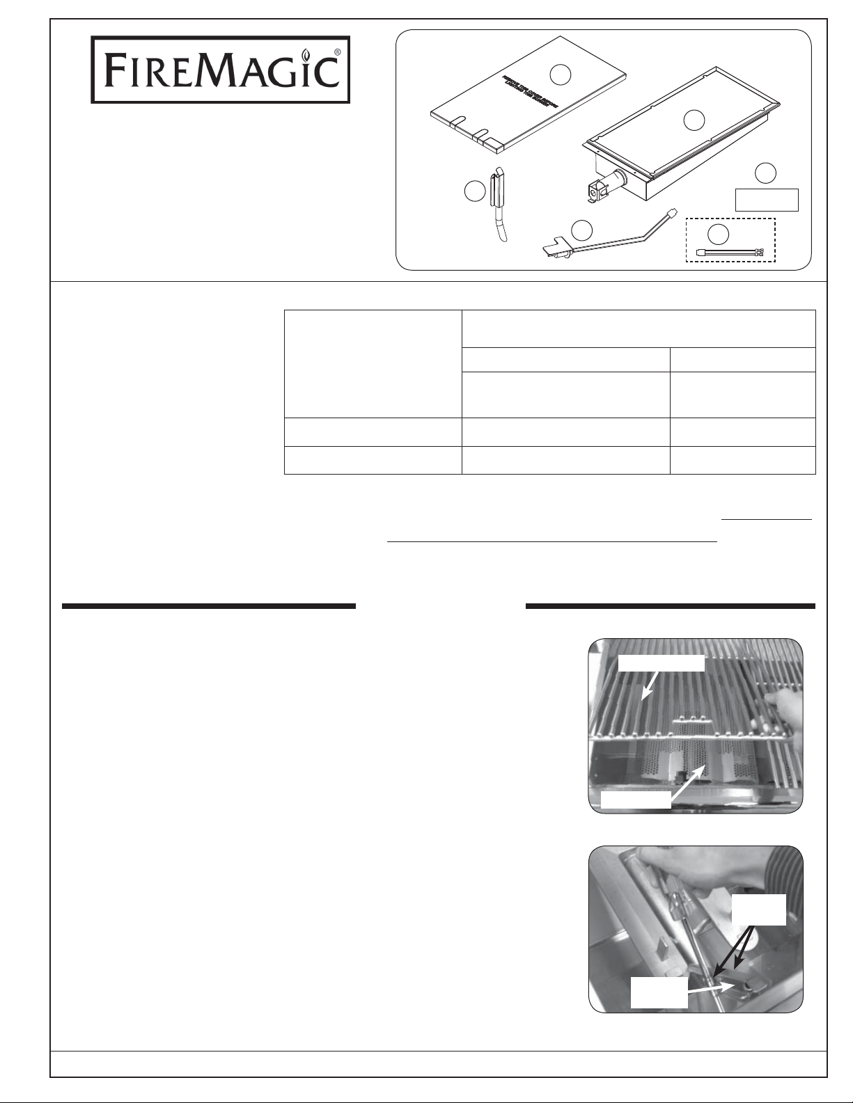
PARTS INCLUDED
1. Infrared burner
2. Electrode assembly
3. Burner cover
4. Label
5. Flash tube
6. Adapter wire*
TOOLS REQUIRED
• Phillips screwdriver
• Pair of needle-nose pliers
• 1
/4 hex nut driver
• 3
/8 hex nut driver
4
5
2
6*
NOTE:
This unit has been retrofi tted
with an infrared burner.
Included parts
Infrared Orifi ce Chart
Table 1-1
Kit Model # 3050 Kit Model # 3060
Grill Models:
A/E660, A/E790, E1060
Grill Models:
A430, A540
Natural Orifi ce 3001-45 3001-49
Propane (L.P.) Orifi ce 3001-55 3001-56
The adapter wire (item #6) is provided for use with Echelon grills
*
that are equipped with ignitor buttons for lighting. (Push to light
confi gurations do not require this adapter.)
INSTALLATION
REMOVING THE OLD BURNER
1. Be sure the grill is completely cool and the gas is completely
shut off. Open the oven lid.
2. Remove the cooking grid from above the burner by lifting it fi rst
from the front and set it aside (see Fig. 1-1).
3. Remove the fl avor grid from above the burner and set it aside (see
Fig. 1-1). The fl avor grid will not be used with the infrared burner.
4. Remove the fl ash tube by removing the two hex nut screws using
the 1/4 inch hex nut driver; pulling it directly away from the grill fi re
wall and off the mounting pin and the ignitor electrode (see Fig.
1-2). Retain screws for installation.
Cooking grid
Flavor grid
Fig. 1-1 Remove cooking and fl avor grid
Hex nut
screws
Old fl ash
tube
ROBERT H. PETERSON CO. • 14724 East Proctor Avenue • City of Industry, CA 91746
REV 6 - 1502230915
Fig. 1-2 Remove the fl ash tube
1
L-C2-251
Page 2
INSTALLATION (cont.)
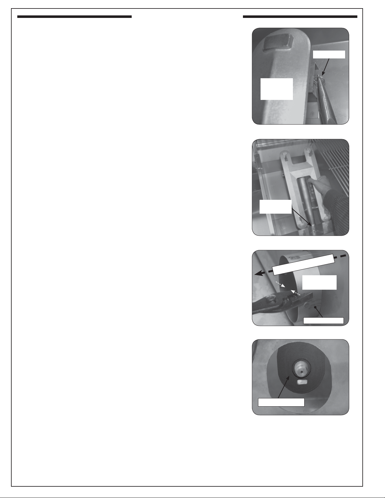
5. Remove the cotter pin from the right rear burner anchoring peg
using needle-nose pliers. Pull it straight out of the cotter pin hole
(see Fig. 2-1).
CAUTION: The burner is heavy.
6. Remove the existing main burner by lifting the pegs extending
from under the back end of the burner out of the two (2) holes on
the bottom of the oven. After the pegs have been freed, move the
whole burner toward the back of the grill so that the burner gas
intake pulls away from the gas orifi ce at the front fi re wall of the
grill (see Fig. 2-2). Then carefully lift the burner out and set it aside.
Retain the clip with the burner so that they can be re-installed in
the future if desired.
7. The grill is equipped with a heatshield kit for each main burner.
This kit is only functional with the standard main burner, and
must be removed for proper infrared burner operation. Use pliers
to remove the diverter tube by bending in each side and pulling
it outwards (see Fig. 2-3), then reach in and remove the silicone
gasket (see Fig. 2-4).
Cotter pin
Right rear
lobe of old
burner
Fig. 2-1 Remove the cotter pin
Burner gas
intake
Fig. 2-2 Remove the burner
Use pliers to remove
Bend sides
inward
Diverter tube
Fig. 2-3 Remove diverter tube
REV 6 - 1502230915
Remove gasket
Fig. 2-4 Remove silicone gasket
2
L-C2-251
Page 3

INSTALLATION (cont.)
INSTALLING THE NEW INFRARED BURNER
1. Use the 3/8 inch hex nut driver to remove the exposed gas orifi ce
and replace it with the correct orifi ce for the new infrared burner
included with your kit (See Table see 1-1. See also Fig. 3-1, 3-2
and 3-3).
Note: You may need to lean over the oven and look back toward the
inside front of the grill to see the orifi ce.
Exposed ignitor
electrode
Exposed gas orifi ce
Echelon Diamond Shown
Front
Burner
Burner
Gas Conduit
Fig. 3-3 Orifi ce location cut away side view
Burner
Control
Knob
Fig. 3-1 Locate the gas orifi ce
Gas orifi ce
Manifold
Orifi ce
Fig. 3-2 Replace the gas orifi ce
REV 6 - 1502230915
3
L-C2-251
Page 4

INSTALLATION (cont.)
2. Pull out and completely remove the drip tray from the grill.
3. Remove the control panel. If needed, refer to the owner's manual
included with your grill.
4. Disconnect the existing electrode wires from the wires attached
to the ignitor module. Leave the electrode attached to the oven
fi rewall.
5. To remove the heat shield, fi rst cut the zip ties. Then lift the heat
shield up and inward slightly to clear the diagonal slots hooked over
the oven fi re wall then pull away from the manifold (see Fig. 4-1).
6. Install the infrared burner by fi rst sliding it over the orifi ce, then
line up the two tabs in back of the burner with the two slots in the
back of the grill and lower them carefully into place (see Fig. 4-2).
(Old electrode)
Lift heat shield up and
away from manifold
Remove zip ties
Fig. 4-1 Remove heat shield
Fig. 4-2 Install new burner
REV 6 - 1502230915
4
L-C2-251
Page 5

INSTALLATION (cont.)
7. Carefully remove the punch-outs located in the forward fi rewall
(see Fig. 5-1).
8. Slide the infrared electrode wire into the large punch-out hole.
Secure in place through the small punch-out with the screw and
nut provided (see Fig. 5-2 and see 5-3).
9. Feed the infrared electrode wire through the hole in the manifold
fi rewall and heat shield.
10. Connect the wire to the main harness wire that used to be connected
to the old electrode (Fig. 5-3). Test the ignitor by pressing the
corresponding ignitor button and observing that the tip of the
ignitor glows orange.
Note: On select Echelon grills, the adapter wire (provided) will need
to be used to connect the new electrode wire to the main
harness wire.
11. Apply the conversion label supplied with this kit to the inside of
the fi re wall behind the control panel so that it does not obscure
any other labels.
12. Reposition the heat shield by hooking the diagonal slots back
over the sheet metal of the manifold fi re wall.
13. Replace the fl ash tube with the one provided in your installation
kit by carefully lining up the two holes in the back of the tube with
the two pins sticking out of the inside front of the grill fi re wall.
Then use the 1/4 inch hex nut driver to lightly tighten both hex
nut screws (see Fig. 5-4).
14. Remove the appropriate punch-outs (on the protective cover) for
your burner and location. Place the cover on the infrared burner.
(See Fig. 6-1.)
15. Reinstall the control panel.
16. Replace the cooking grid so that the cut-out section of the grid
is in front.
Remove
punch-outs
Fig. 5-1 Remove Punch-outs
Fig. 5-2 New electrode
Electrode installed
New wires
Note: FLAVOR GRIDS ARE NOT TO BE USED with infrared
burners.
REV 6 - 1502230915
5
Main harness wire
Fig. 5-3 Connect new electrode wires
Hex nut
screws
New fl ash
tube
Fig. 5-4 Replace the fl ash tube
L-C2-251
Page 6

O
FF
HI
LIGHT
LOW
OFF
HI
LIGHT
L
O
W
INFRARED BURNER OPERATION
The infrared (IR) searing burner (optional) cooks with
a powerful radiant heat.
Cover
Cut-out for
Flash tube
Ignitor
Flash tube
Fig. 6-1
electrode
Light the infrared burner following the LIGHTING
INSTRUCTIONS in this manual or printed on the
drip tray. Follow these guidelines when operating the
Infrared burner:
• DO NOT place food on the cooking grid until
the IR burner glows orange (Fig. 6-3). Drippings
are heated and evaporate instead of sticking to and
impairing burner function.
• For cleaning purposes; always leave your burner
on (after cooking) for an additional 5 minutes, to
allow for a burnoff period. This is important to
keep your burner clean and operating properly.
WARNING
Only handle the infrared burner cover when the
unit is cold or with a well-insulated long-handled
tool or heat resistant gloves.
SIDE VIEW (with cover on)
Ignitor
Cover
Food
particles
or debris
electrode
Flash
tube
Fig. 6-2
NO foreign
objects
Airborne
dust or
grease
Drippings
and other
liquids
Burner ceramic must be protected with cover when
burner is not in use.
SIDE VIEW
(burner on HI LIGHT
and glowing orange)
Ignitor
electrode
Flash
tube
As the burner is self cleaning (at full temperature);
avoid the use of cleaners or abrasives.
• When not in use, always cover the infrared burner
with the stainless-steel cover. This protects the
burner from drippings (from other cooking), airborne
particles, and foreign objects (Fig. 6-2).
• Do not strike or scratch the burner ceramic as it
may chip, crack, or break (Fig. 6-2).
Note: Digital thermometer does not give accurate
readings for infrared burners.
Important: When grilling with the infrared burner,
always place a cooking grid above it.
The cooking grid must be removed for
rotisserie cooking.
CAUTION: DO NOT operate your IR burner with the
oven hood closed.
CAUTION: Never attempt to operate the IR burner
with the protective cover in place.
Fig. 6-3
Drips and particles evaporate before hitting infrared
burner when cooking at the maximum setting.
Note: Flavor grids are not to be used with infrared
burners.
To ensure proper operation, all infrared burners
(back and main) must be operated on the HI setting
for a minimum of 10 minutes. Thereafter, the fl ame
may be lowered as desired.
CAUTION: Always monitor the infrared burner fl ame
when operated on low, as it may blow
out in high-wind conditions.
6
 Loading...