

Page 1
INFRARED BURNER KIT
INSTRUCTIONS
Model # 3049 (A790, A660, & A530)
Model # 3051 (A540, & A430)
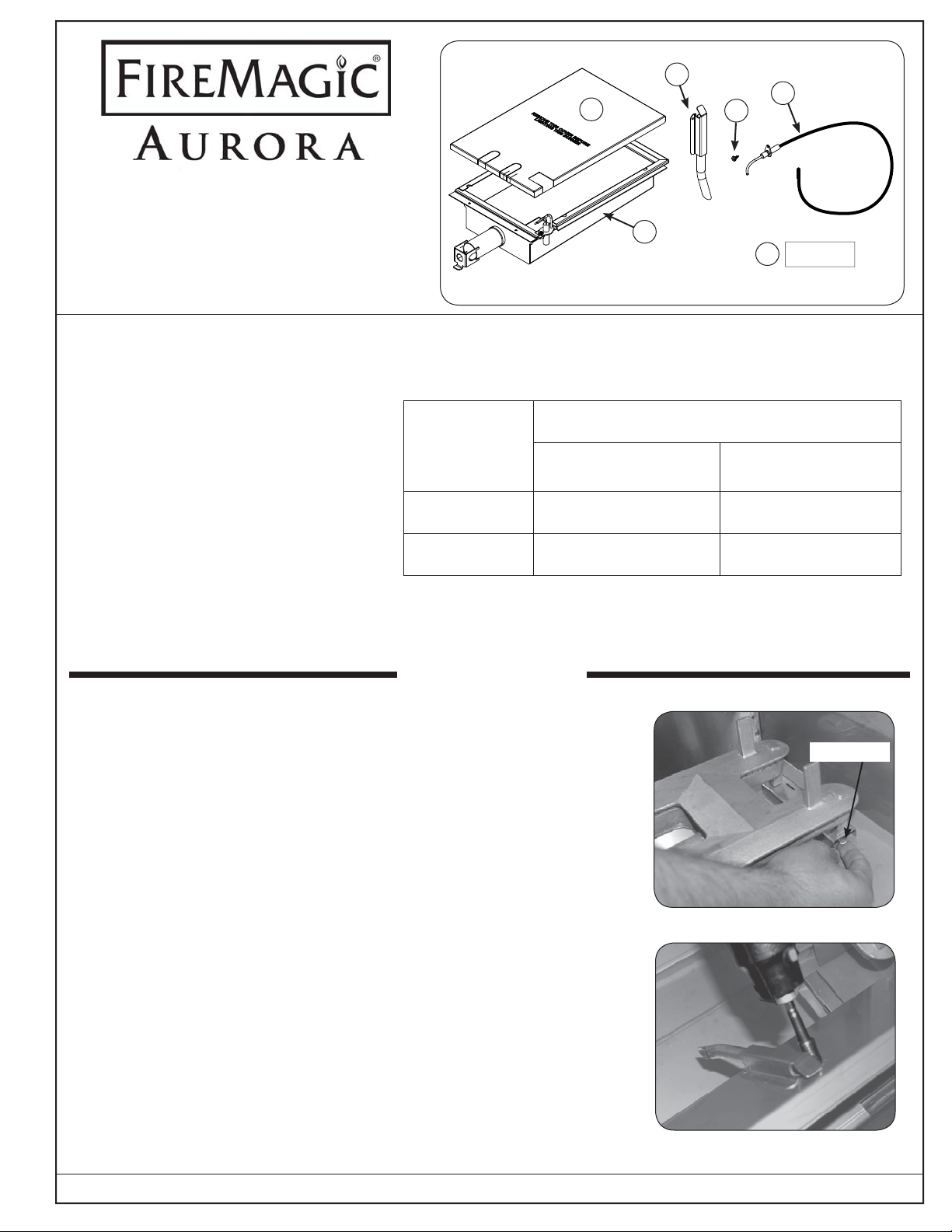
PARTS INCLUDED
1. Infrared burner
2. Ignitor wire
3. Self-tapping sheet-metal screw
4. Infrared cover
5. Conversion label
Table 1-1
6
4
1
Included parts
Infrared Orifi ce Chart
Models A430, A540
2
3
NOTE:
This unit has been retrofi tted
5
with an infrared burner.
Models A530, A660,
A790
6. Lighting tube
TOOLS REQUIRED
Natural 3001-49 3001-45
Propane (L.P.) 3001-56 3001-55
• Phillips screwdriver
• 9
/16 open-end wrench
• 1
/4 nut driver or socket wrench
INSTALLATION
REMOVING THE LEFT MOST MAIN BURNER
1. Be sure the grill is completely cool and the gas is completely
shut off. Open the oven lid and/or remove the warming rack and/
or rotisserie rod as needed to access the cooking grids.
2. Remove the cooking grid and fl avor grid from the left-most burner.
Set the cooking grid aside. The fl avor grid will not be used with
the infrared burner, and should be stored away.
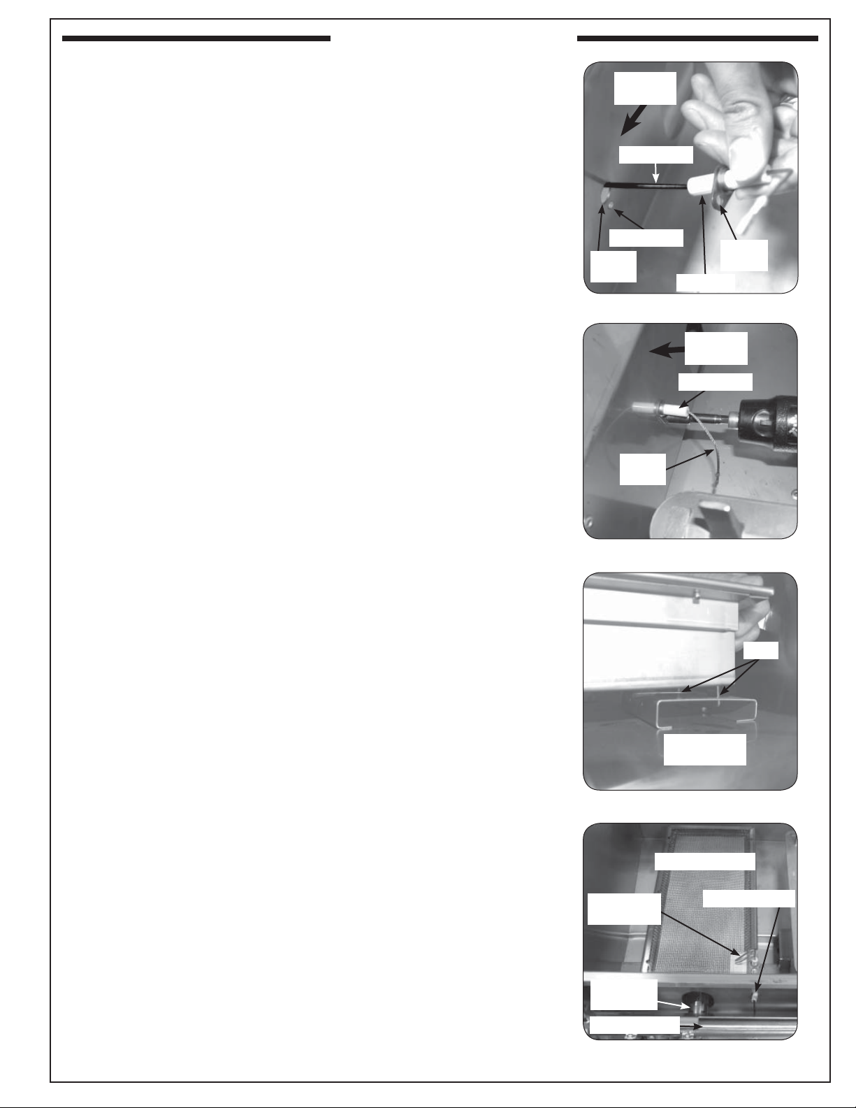
3. Remove the left most burner by fi rst removing the burner clip (see
Fig. 1-1) from under the back of the burner support. Then lift the
back of the burner up out of the fi rebox by grasping the back and
pulling upward. Continue to lift the back of the burner up while
moving the whole burner back and out so that it pulls away from
the forward fi re wall opening and the orifi ce. Retain the clip
the burner so that they can be re-installed in the future if desired.
with
Burner clip
Fig. 1-1 Remove the grids and burner clip
4. Remove the lighting tube by removing the two screws with the
1
/4 nut driver (see Fig. 1-2). Retain the screws for attaching the
new lighting tube.
ROBERT H. PETERSON CO. • 14724 East Proctor Avenue • City of Industry, CA 91746
REV 3 - 1302260945
1
Fig. 1-2 Remove old lighting tube
L-C2-280
Page 2

INSTALLATION (cont.)
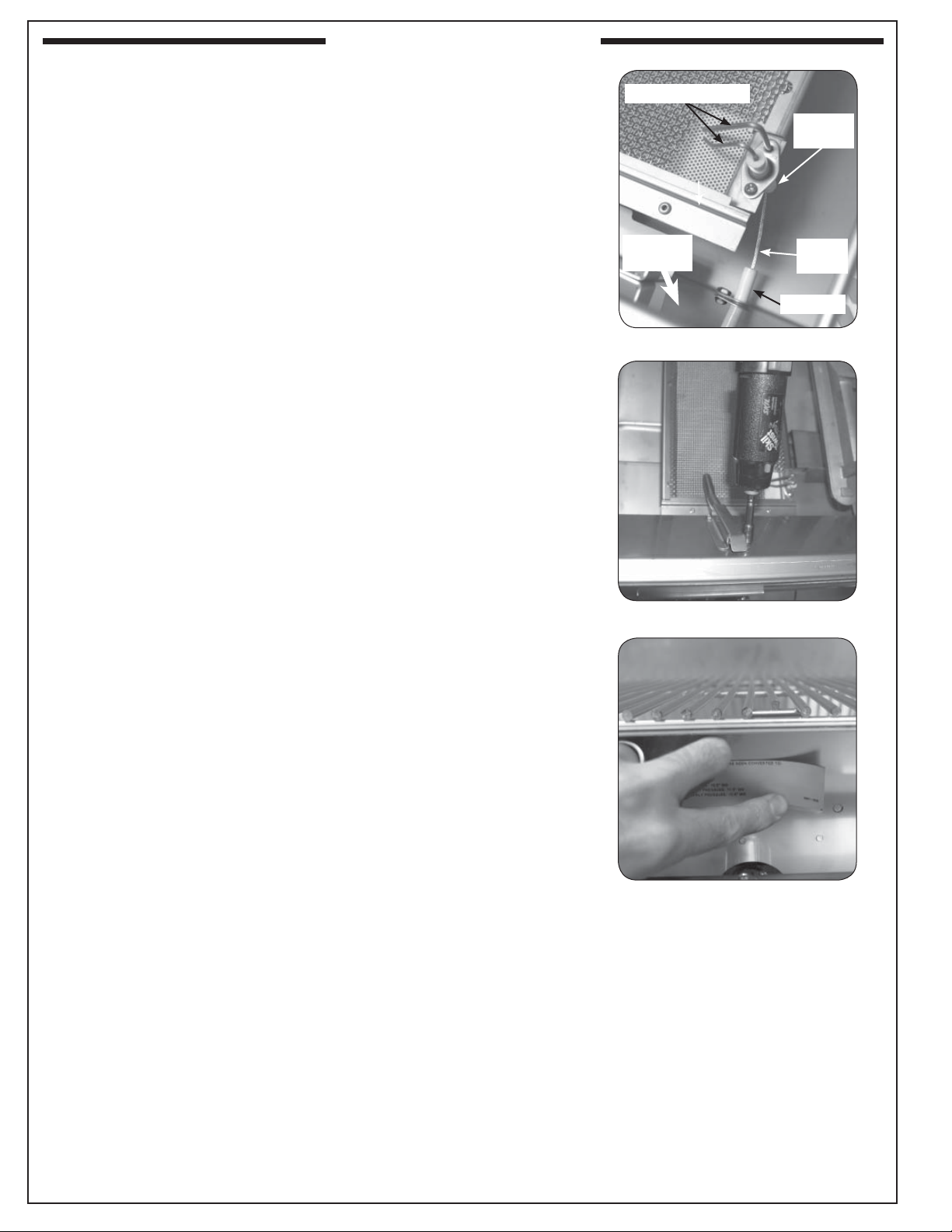
5. The grill is equipped with a heatshield kit for each main burner.
This kit is only functional with the standard main burner, and
must be removed for proper infrared burner operation. Use pliers
to remove the diverter tube by bending in each side and pulling
it outwards (see Fig. 2-1), then reach in and remove the silicone
gasket (see Fig. 2-2).
6. Pull out and completely remove the drip tray from the grill.
Use pliers to remove
Bend sides
inward
7. With the burner valves in the OFF position, pull the valve knobs
from their stems. Use a Phillips screwdriver to remove the control
panel fastener screws on either side of the grill control panel (see
Fig. 2-3). Release the control panel by lifting it slightly and remove
it from the grill. Make sure to retain the screws and fi nish washers
for re-attaching the control panel.
Note: To protect the wiring harness, carefully lift the control panel
away from the frame and let it rest on the attached chain.
8. Lift the heat shield up and inward slightly to clear the diagonal slots
hooked over the oven fi re wall then pull away from the manifold
(see Fig. 2-4).
9. Remove the existing ignitor wire by fi rst sliding the rubber sleeve
back off the ignitor, then pulling the wire to detach from the ignitor.
Next remove the ignitor nut on the control panel side of the fi re wall
with a 9/16 open-end wrench (see Fig. 2-4) and remove the ignitor
box from inside the oven. Remove the rubber sleeve from the wire
and pull the wire through the heat shield and the insulating tube
in the manifold fi re wall. Disconnect the other end of the ignitor
wire from the ignitor module (see Fig. 2-5).
Diverter tube
Fig. 2-1 Remove diverter tube
Remove gasket
Fig. 2-2 Remove silicone gasket
Screw
Control panel
Valve
stem
Fig. 2-3 Remove control panel
Old ignitor
Heat shield
Fig. 2-4 Remove heat shield and old ignitor
Remove wire from
ignitor module
REV 3 - 1302260945
Fig. 2-5 Remove old ignitor wire
2
L-C2-280
Page 3
INSTALLATION (cont.)
INSTALLING THE NEW INFRARED BURNER
1. Locate the new ignitor wire with the insulator attached and thread
the wire end through the hole in the oven fi re wall left by the old
ignitor, from the oven side as shown in Fig. 3-1. Continue to thread
the wire end through the insulator tube in the manifold fi re wall and
through the slot in the heat shield, then route it toward the ignitor
module on the right. (Hint: wrap around existing wire bundle.)
2. Attach the other end of the new ignitor wire (the insulated end) to
any male connector on the back of the ignitor module (reference
Fig. 2-5).
Important: Test all electrodes for spark before securing the control
panel to the frame (see also the section on battery
replacement in your owners manual).
Note: The wires can be plugged into any terminal.
3. Attach the insulated portion of the ignitor wire to the inside of the
oven fi re wall by placing the screw (included) through the bracket
hole and into the hole in the fi re wall (see Fig. 3-1 and Fig. 3-2).
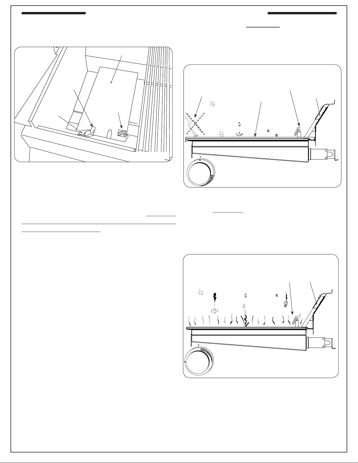
4. Place the new infrared burner gas intake tube in the hole in the
oven fi re wall and over the orifi ce fi tting, sliding it forward from
behind the control panel frame, so the orifi ce is centered inside
the burner gas tube. Set it gently onto the rear burner support,
making sure the tabs on the back burner bottom each fi t through
their respective slots in the rear burner support. This is critical to
the safe function of the grill. (See Fig. 3-3 and Fig. 3-4.)
Front fi re
wall
Ignitor wire
Screw hole
Ignitor
hole
Fig. 3-1 Screw the new wire to the fi re wall
Ignitor
wire
Fig. 3-2 Screw the new wire to the fi re wall
Insulator
Bracket
hole
To front
fi re wall
Insulator
Tabs
Rear burner
support
Fig. 3-3 Sliding tabs into support
Infrared burner
Ignitor
electrodes
Gas intake
tube
Gas manifold
Fig. 3-4 Infrared burner installed
Wire insulator
REV 3 - 1302260945
3
L-C2-280
Page 4
INSTALLATION (cont.)
5. Connect the non-insulated metal end of the ignitor wire to the
bottom of the ignitor electrode assembly at the forward right of the
infrared burner (see Fig. 4-1).
6. Attach the new lighting tube (Fig.4-2) in place of the old one
securing it with the old screws.
7. Apply the conversion label supplied with this kit to the inside of the
fi re wall behind the control panel so that it does not obscure any
other labels (Fig. 4-3).
8. Reposition the heat shield by hooking the diagonal slots back over
the sheet metal of the manifold fi re wall.
9. Replace the control panel on the frame so the front lip of the
control panel hangs from the forward lip of the frame. Re-secure
the control panel with the fastener screws.
10. Replace the control knobs.
11. Replace the drip tray.
12. Replace the cooking grid. (DO NOT place the fl avor grid on the
infrared burner. It is not designed for use on an infrared burner,and
should be stored away.)
Ignitor electrodes
Connect
here
Front fi re
wall
Fig. 4-1 Connect wire to electrode assy.
Ignitor
wire
Insulator
Fig. 4-2 Install new lighting tube
Fig. 4-3 Apply the conversion label
REV 3 - 1302260945
4
L-C2-280
Page 5
O
F
F
HI
LIGHT
LOW
OFF
HI
LIGHT
L
O
W
OPTIONAL INFRARED BURNER OPERATION
The infrared (IR) searing burner (optional) cooks with
a powerful radiant heat.
Cover
Cut-out for
Flash tube
Ignitor
Flash tube
electrode
Fig. 5-1
Light the infrared burner following the LIGHTING
INSTRUCTIONS in this manual or printed on the
drip tray. Follow these guidelines when operating the
Infrared burner:
• DO NOT place food on the cooking grid until
the IR burner glows orange (Fig. 5-3). Drippings
are heated and evaporate instead of sticking to and
impairing burner function.
WARNING
Only handle the infrared burner cover when the
grill is cold or with a well-insulated long-handled
tool or heat resistant gloves.
SIDE VIEW (with cover on)
Ignitor
Cover
Food
particles
or debris
electrode
Flash
tube
Fig. 5-2
NO foreign
objects
Airborne
dust or
grease
Drippings
and other
liquids
Burner ceramic must be protected with cover when
burner is not in use.
• For cleaning purposes; always leave your burner
on (after cooking) for an additional 5 minutes, to
allow for a burnoff period. This is important to
keep your burner clean and operating properly.
As the burner is self cleaning (at full temperature);
avoid the use of cleaners or abrasives.
• When not in use, always cover the infrared burner
with the stainless-steel cover. This protects the
burner from drippings (from other cooking), airborne
particles, and foreign objects (Fig. 5-2).
• Do not strike or scratch the burner ceramic as it
may chip, crack, or break (Fig. 5-2).
Note: Digital thermometer does not give accurate
readings for infrared burners.
Important: When grilling with the infrared burner,
always place a cooking grid above it.
The cooking grid must be removed for
rotisserie cooking.
SIDE VIEW
(burner on HI LIGHT
and glowing orange)
Ignitor
electrode
Flash
tube
Fig. 5-3
Drips and particles evaporate before hitting infrared
burner when cooking at the maximum setting.
CAUTION: Never attempt to operate the IR burner
with the protective cover in place.
Note: Flavor grids are not to be used with infrared
burners.
5
Page 6
INFRARED BURNER NOTES PAGE
Please use this page to record any information about your infrared burner that you may want to have at hand.
6
 Loading...