

Page 1
INFRARED BURNER
2 series Model # 3046
1 series Model # 3047
INSTALLER: Leave these instructions with consumer.
CONSUMER: Retain for future reference.
Important: READ THESE INSTRUCTIONS CAREFULLY
BEFORE STARTING INSTALLATION OR USE.
FITS ALL FIRE MAGIC STAINLESS STEEL
UNIBODY GRILLS
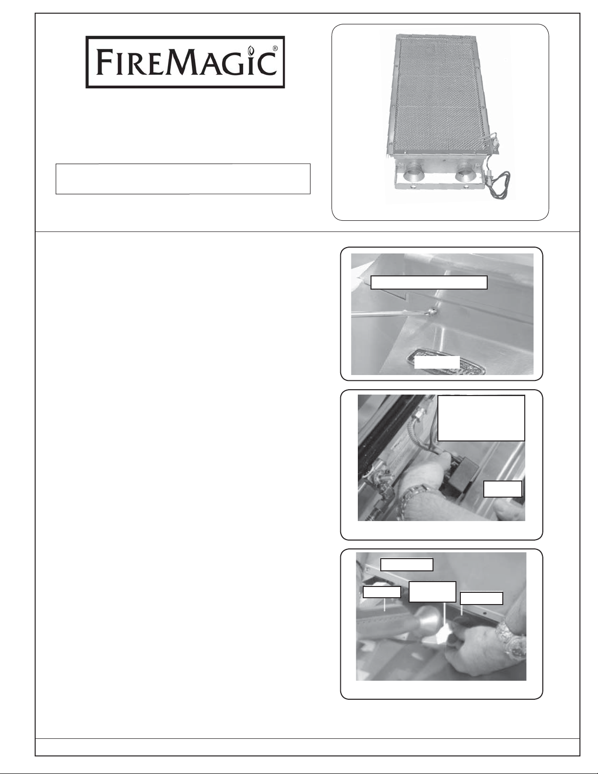
The Fire Magic infrared (IR) burner is ideal for searing
and fast cooking where needed, and gives a more
intense heat than standard burners. Replacing 2 main
burners with the infrared burner is quick and easily done
by using the instructions set out below.
TO MAKE THE INSTALLATION OF THIS UNIT
TROUBLE FREE, READ THIS DOCUMENT
THOROUGHLY AND THEN CAREFULLY FOLLOW
THE INSTRUCTIONS GIVEN. OBSERVE THE
CAUTIONS LISTED ON THE BACK PAGE.
Note: Use your grill operating instructions to identify
parts and locations mentioned in these
instructions.
1. When they are cool enough to handle, remove
cooking grids, and fl avor grids (if equipped).
2. Remove the face screws (Fig. 1-1) & burner valve
knobs. Place aside for later use.
3. Pull out drip tray and carefully lift face away just
enough (about 4"- 6") to enable you to reach behind
face and disconnect the wires attached to the spark
ignitor (Fig. 1-2). Set the face safely aside.
Infrared burner (top view)
Remove face screws
Fig. 1-1
Move face away
slightly, then
remove the ignitor
wires
Face
Fig. 1-2
Removing:
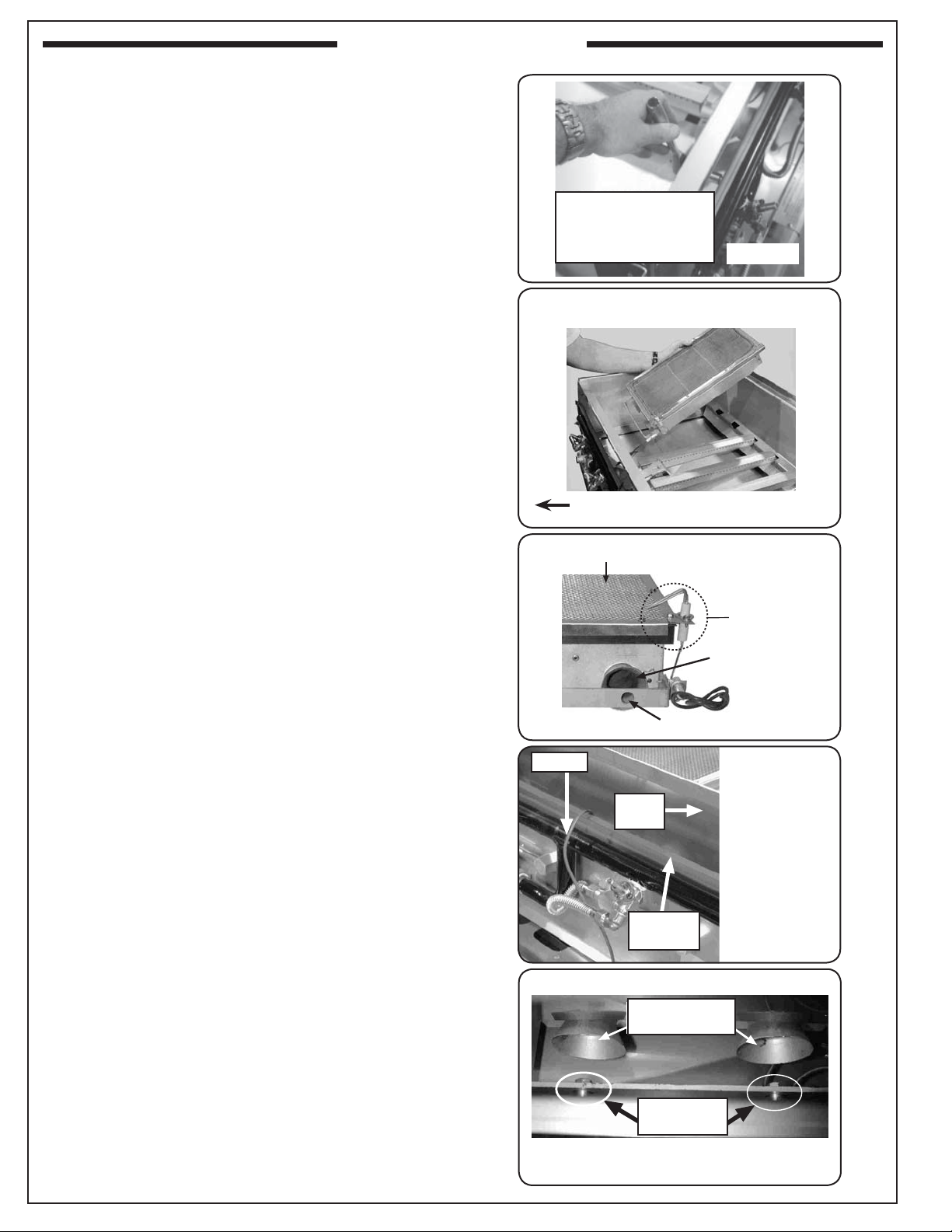
4. Remove the two burners, air shutters, and the
springs (Fig. 1-3) that you will replace with the IR
burner.
Note: The two far left burners should be replaced.
For Elite, Monarch, and Deluxe grills, the ignitor box
must also be removed. For Elite, Monarch, and Custom
grills, the crossover box next to the burners must also
be removed.
ROBERT H. PETERSON CO. • 14724 East Proctor Avenue • City of Industry, CA 91746
REV 2 - 1208201328
Burner
Air
shutter
Spring
Fig. 1-3
1
L-C2-155
Page 2
INSTALLATION (cont.)
MANIFOLD
PLATE
INNER
LINER
IR WIRE
BURNER GAS
INLETS
BARBECUE
ORIFICES
5. Remove and replace existing orifi ces (Fig. 2-1)
with the ones supplied with your IR burner. For 2
series units, supplied orifi ce size is #49 for natural
gas and #57 for propane gas. For 1 series units,
supplied orifi ce size is #53 for natural gas and #63
propane gas.
6. Carefully place the IR burner into the fi rebox (
2-2), ensuring that:
a. the burner gas inlets (Fig. 2-3) face the front
of the grill, or the right on Deluxe models.
b1. the black ignitor wire passes up under the inner
liner & over the manifold plate (see Fig. 2-4)
OR
b2. for the Deluxe, the wire wraps around the
outside of the burner manifold and follows gas
line - do not pass across inside of the fi rebox.
c. the IR burner orifi ce ports fi t over the orifi ces (Fig.
2-5).
Fig.
Remove existing
orifi ces & replace with
new orifi ces supplied
Inserting IR burner after removal of
burners, air shutters, & springs
Fig. 2-1
Fig. 2-2
Front of grill
IR BURNER TOP
IR burner ports
Note: 2 left burners
removed
Fig. 2-3
IGNITOR
Ignitor
Burner gas inlet
BURNER GAS
INLET
REV 2 - 1208201328
ORIFICE PORT
Orifi ce port
IR wire
Inner
liner
Manifold
plate
Fig. 2-4
Pass the IR
ignitor wire
under the grill
liner and over
the manifold
plate
Fig. 2-5
Burner gas
inlets
Grill
orifi ces
Slide IR burner forward so that the orifi ce
ports fi t over the orifi ces
2
L-C2-155
Page 3

INSTALLATION (cont.)
FIT IR BURNER HANGERS INTO
SLOTS AT BACK OF FIREBOX
d. the rear hangers fi t into the slots at the back
of the fi rebox (see Fig. 3-1).
7. When the IR burner is fi rmly in place (Fig. 3-2),
connect the IR ignitor wire to the spark ignitor (when
you replace the grill face) (Fig. 3-3) in the following
confi gurations:
For Deluxe grills:
plug in the IR burner ignitor wire; re attach the
ground wire.
For Regal & Custom grills WITHOUT
backburners:
unplug the ground (green) wire from the ignition
module and plug in the IR burner wire.
For Regal & Custom grills WITH backburners
and a 2-pole spark module:
the existing spark module must be replaced with
a 4-pole module (Part # 3199-34). The installation
instructions are supplied with the replacement
module.
When it has been replaced, plug in your IR burner
wire to a spare pole, and add a ground wire (ground
to grill manifold nut). Do not leave the 4th pole open,
as this will affect the overall sparking potential.
Fit IR burner hangers into the slots
at the back of the fi rebox
Fig. 3-1
IR burner in place
Note: No cross ignition between IR
and main burners will occur.
Fig. 3-2
Connect IR wire to spark ignitor.
(Note: Ground wire disconnected.)
Important: All plugs on the spark module must have
8. Carefully replace the face, checking all wires are
connected to the spark ignitor.
9. Replace the burner valve knobs. Test the spark
ignitor and look for a spark at all electrodes including
IR ignitor. If spark is present, replace fl avor grids
(DO NOT place a fl avor grid on IR burner), cooking
grids, and face screws. If no spark is detected check
that the wiring is correctly connected to the spark
ignitor, and that battery has suffi cient power. If in
doubt replace the battery.
Important: Ensure the bare IR ignitor electrode wire
a ground or ignitor wire attached.
Fig. 3-3
Ensure bare ignitor wire does not
touch the side of the IR burner
does not touch the side of the IR burner
as this will cause shorting and no spark
at the electrode tips (Fig. 3-4).
Fig. 3-4
REV 2 - 1208201328
3
L-C2-155
Page 4

INSTALLATION (cont.)
10. Turn on the gas and ignite as normal, ensuring your
IR burner lights. There will be no cross ignition to or
from the IR burner. Replace drip tray before cooking.
ALWAYS REMOVE THE IR BURNER COVER
BEFORE IGNITING THE IR BURNER
ALWAYS REPLACE THE IR BURNER COVER
AFTER EACH USE.
Note: Place the IR burner cover over it so that the
deep end (longer side) rests at the back of the
burner, and the short end is at the front (see
Fig. 4-1 & 4-2).
11. Place the silver “Important” label supplied on the
oven handle above the IR burner.
IR burner in place
Fig. 4-1
Fig. 4-2
Note: Cover sits over spark ignitor and
IR burner cover in place
the long side is at the rear.
Front of IR burner Rear of IR burner
OPERATION
FOLLOW THE LIGHTING INSTRUCTIONS IN YOUR GRILL INSTALLATION AND OPERATION MANUAL.
Note: The infrared burner will take 5-9 seconds to ignite. THIS IS NORMAL. It will take 3-5 minutes to heat up.
DO NOT TURN THE IR BURNER DOWN BELOW MEDIUM - THE BURNER MAY GO OUT.
IMPORTANT - OBSERVE THESE CAUTIONS:
1. THE INTENSE HEAT FROM AN INFRARED BURNER CAN CAUSE BURNS. USE EXTREME CAUTION
WHEN USING YOUR IR BURNER.
2. DO NOT OPERATE YOUR IR BURNER WITH THE OVEN/HOOD CLOSED.
3. REMOVE THE IR BURNER COVER BEFORE IGNITING THE IR BURNER.
4. WHILE COOKING, DO NOT TURN IR BURNER
GO OUT.
5. WHEN NOT IN USE, ALWAYS COVER THE INFRARED BURNER WITH THE COVER. THIS PROTECTS
THE BURNER FROM DRIPPINGS (FROM OTHER COOKING), AIRBORNE PARTICLES, AND FOREIGN
OBJECTS.
6. DO NOT ATTEMPT TO DISASSEMBLE YOUR IR BURNER.
SETTING DOWN BELOW MEDIUM OR THE BURNER MAY
Important: Attach the supplied “Important” label to your oven/hood handle for safety and reference.
GENERAL NOTES
1. Infrared heat cooks differently than that produced from traditional burners. IR burners cook with an intense,
direct heat that will immediately sear in the natural juices of your food, resulting in a more moist, fl avorful
food. However, the intense heat also reduces the cooking time of your food. If left on the grill too long the food
may become dry or overcooked very quickly. DO NOT LEAVE A GRILL COOKING FOOD UNATTENDED.
2. For large or thick cuts of meat you may wish to use your IR burner to sear the meat and then use the
conventional burners to fi nish cooking the meat thoroughly. This will keep the meat from being overcooked.
REV 2 - 1208201328
4
L-C2-155
 Loading...