

Page 1
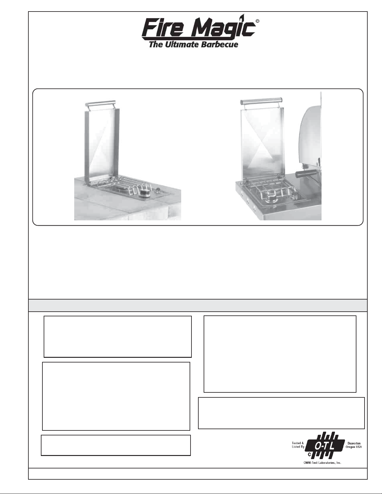
SIDEBURNER
15,000 BTU
Natural Gas or Propane Gas
SIDEBURNER
SHELF MODELS #25326-016 & #25336-016
DROP-IN MODELS #3275 & #3280
BRICK OPENING: 8 3/4" x 14 1/4" x 4" deep.
Side shelves and connector kits for mounting side burners
on portable car ts or in countertop enclosures are packaged separately.
INSTALLER: Please leave these instructions with the consumer. CONSUMER: Retain for future reference.
INSTALLATION AND OPERATING INSTRUCTIONS
FOR YOUR SAFETY
Do not store or use gasoline or other
flammable vapors and liquids in the vicinity
of this or any other appliance.
WARNING: Improper installation,
adjustment, alteration, service or
maintenance can cause injury or property
damage. Refer to this manual. For assistance
or additional information consult qualified,
professional installer, service agency or the
gas supplier.
We reserve the right to amend product
specifications without prior notice.
Robert H. Peterson Co. • 14724 East Proctor Avenue, • City of Industry, CA 91746
REV A1 022305
FOR YOUR SAFETY
WHAT TO DO IF YOU SMELL GAS
1. Shut off the gas to the appliance.
2. Extinguish any flame.
3. Open lid.
4. If odor continues, immediately call
your gas supplier or fire department.
This manual may not be copied, photocopied,
reproduced, translated, or published in any electronic
or machine-readable form in whole or in part without
prior written approval of Robert H. Peterson Co.
Certified to ANSI: Z21.58
1
No. L-C2-02505
Page 2
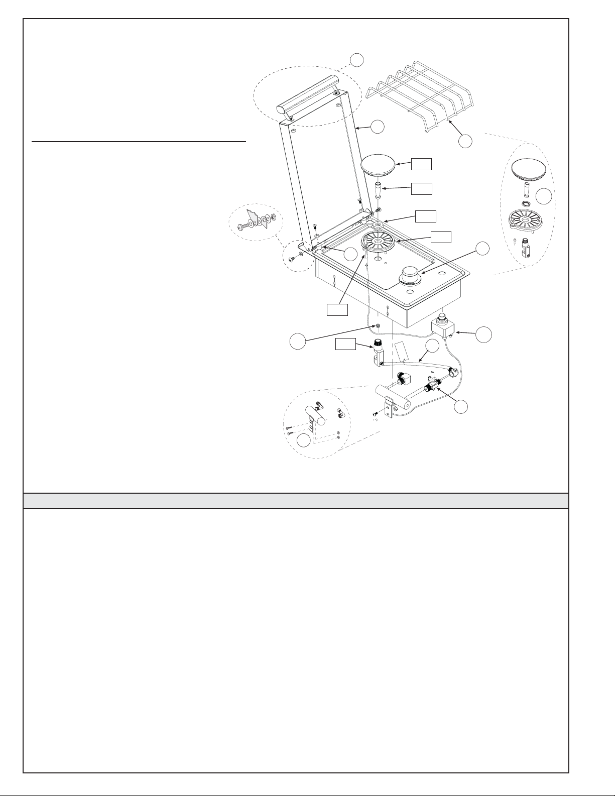
SIDEBURNER PARTS LIST
1
Item Part Description(Qty.)
No. No .
1. 3275-06 Handle assembly
2. 3275-04 Lid, porcelain
OR 3280-04 Lid, S.S.
3. 3275-26 Lid stop (2)
4. 3275-10 Burner grid
5. 3005 Valve, w/o knob
6. 3020 Knob
7. 3275-39 Valve manifold assembly
8. 3275-35 Gas connector tube
9. 3275-32 Side burner assembly , complete
Comprising of:
9A Orifice housing
9B Ignitor electrode
9 C Venturi tube
9 D Lock nut
9E Burner base
9F Burner cap
10. 3001-49-1 Burner orifice, nat gas #49
OR 3001-56-1 Propane gas #56
11. 3199-32 Ignitor spark generator
10
9 B
9 A
2
4
9 F
9 C
9 D
9 E
3
8
6
11
5
9
PREP ARING FOR INST ALLA TION OF Y OUR FIRE MAGIC SIDE B URNER
Your Fire Magic Sideburner is designed to complement
your Fire Magic Barbecue. It provides a convenient,
efficient cooking surface for side dishes that require
bottom heat only.
TOOLS REQUIRED: A pair of wrenches, pliers or vice
grips for the gas connection.
CODE AND SUPPLY REQUIREMENTS: This burner
must be installed in accordance with local codes and
ordinances or, in the absence of local codes, with the
National Fuel Gas Code, ANSI Z223.1.
This appliance and its individual shutoff valve must be
disconnected from the gas supply piping system when
testing the system at pressures in excess of 1/2 psig.
The appliance must be isolated from the gas supply piping
system by closing its individual manual shutoff valve
during any pressure testing of the gas supply system at
pressures up to and including 1/2 psig.
WHERE TO INSTALL YOUR SIDEBURNER
Fire Magic Sideburners are designed for outdoor use
only.
7
WARNING: Sideburners must be installed in masonry or
other type of fireproof enclosure. The unit is not insulated
and therefore must be installed with 18" of side and back
clearance from unprotected combustible materials such
as wood, plastic, or stucco with wood framing. Do not
install under overhead unprotected flammable
construction. A 4" clearance to any back wall is required
to open the lid properly.
This is a drop-in type unit. The unit must be
removable for gas hookup, servicing and burner
adjustment.
PROPER VENTILATION: Proper ventilation of your
sideburner must be maintained to ensure proper
performance. Do not operate with lid closed.
VENTILATION OF ENCLOSURES
When using propane gas, take EXTREME CAUTION to
ensure ample ventilation of gas vapor. Propane vapor is
invisible and heavier than air. A DANGEROUS
EXPLOSION could occur, resulting in SERIOUS INJURY,
OR LOSS OF LIFE if propane gas is allowed to accumulate
and then ignite.
2
Page 3

Only one propane gas cylinder may be located in an
enclosure. Extra or spare cylinders must be stored
outdoors out of the reach of children and outside of any
building, garage or other enclosed area. READ AND
FOLLOW ALL WARNINGS PROVIDED WITH PROPANE
GAS CYLINDERS. Never locate a cylinder under or
near the barbecue unless sufficient ventilation and
shielding is provided to prevent any heating of the
cylinder, regulator and rubber hose.
Propane Cylinder Enclosures
To prevent invisible combustible gas from accumulating
in your cylinder enclosure, you must provide adequate
ventilation. This is accomplished by
EITHER of the
following methods. One side of the gas cylinder enclosure
can be left completely open to the outside
OR by
providing four (4) v entilation openings. Two openings are
to be at the cylinder valve level (approx.16” above the
floor) and on opposite walls of the enclosure. Two more
openings must be at the floor level on opposite sides of
the enclosure. The floor level openings must start at the
floor and shall extend no higher than 5” above the floor.
Each opening must have a minimum of 10 square inches
(64.5 cm
2
) of free area. T o achiev e the proper v entilation,
you may drill a series of holes, omit the grout from
masonry joints or replace a brick with a hardware cloth
screen. If the floor in the cabinet is raised and the space
beneath the cabinet is open to the outside, the lower
ventilation openings may be in the floor.
FOR YOUR SAFETY, you must provide these openings
for drainage, replacement air and cross ventilation of
any storage area exposed to possible leakage from gas
connections, the barbecue or propane cylinder.
HOUSEHOLD PROPANE GAS SERVICE
Consult your gas supplier for ventilation and regulator
requirements when connecting to a HOUSEHOLD
propane supply.
EXHAUST REMO V AL: When installed under a patio roof,
the side burner area should be under a hood with an
exhaust fan.
GAS SUPPLY PLUMBING REQUIREMENTS: Rigid 1/2"
black steel pipe is required to conduct the gas supply
into the masonry opening for connection to the unit. Apply
pipe joint compound (resistant to all gasses) to all male
pipe fittings and tighten all joints securely. Do not use
pipe joint compound to connect
flare fittings. The
pipe should enter
4"
14 1/4"
COUNTER
TOP
enclosure either
from bottom or
6" CLEARANCE
from any side at
least 4" below the
countertop (see
Figure 1).
NOTE:Any
ALSO ALLOW SP A CE FOR HOOKUP
SIDE VIEW
Figure 1
protrusion into the
enclosure higher than 4" below countertop will obstruct
the frame and prevent the unit from dropping into place.
SAFETY NOTE: An external valve (with a removable key)
in the gas line is recommended for safety.
GAS SUPPL Y AND MANIFOLD PRESSURES:
For Natural Gas - normal 7" water column, minimum
5", maximum 10-1/2". For Propane Gas - normal 11"
water column, minimum 8", maximum 13". A REGULATOR MUST BE PROVIDED AT THE BOTTLE OR GAS
SOURCE FOR USE WITH PROPANE GAS.
INST ALLING Y OUR FIRE MA GIC SIDE BURNER (BUIL T -IN APPLICATION)
1. CHECKING FUEL AND PROPER ORIFICES: Y our Fire
Magic Sideburner is equipped with orifices for natural
gas unless otherwise indicated. For propane gas, smaller
orifices must be installed to avoid hazardous overheating.
The orifice size for Natural Gas is #49 (drill size) and for
Propane Gas, the orifice size is #56 (drill size). Check
the orifice size by removing the burner cap (Item#9F)
and the venturi tube (Item #9C) and looking down through
the hole in the center (see Figure 2 for the location of
the orifice). The drill size is stamped on the orifice. If the
number is not visible you may have to remove the orifice
(as detailed below) in order to read the number stamped
on the side of the orifice.
To remove or change an orifice, you need a 3/8" nut
driver or small wrench. Loosen the orifice using the nut
driver, approaching
from above, or by
approaching from
underneath the burner
using a small wrench.
Remove (check the
number on the side if
needed) and replace
with the correct sized
orifice for your gas type.
Figure 2
BURNER - TOP VIEW
ORIFICE
2. CONNECTING THE GAS SUPPLY TO YOUR FIRE
MAGlC SIDEBURNER:
a. The burner manifold has a 3/8” male flare fitting gas
inlet elbow. A 3/8" female flare fitting connector nut is
required to hook the gas supply to the burner.
b. Use a stainless steel flex connector to bring the gas
supply from the gas line stub or propane gas tank to the
sideburner manifold. A 3/8" x 24" or 36" flex connector is
suitable for most installations.
CAUTION: Use only a C.S.A. listed stainless steel flex
connector. Do not use a rubber hose or plastic hose
within the enclosure for your sideburner, it will leak
resulting in an explosion and/or serious injury.
NOTE: For installation in a portable barbecue car t, see
the installation instructions packed with the sideburner
shelf and connector kit. Also refer to the portable cart
instruction section for attaching shelves.
c. Be sure the gas supply is 'OFF'. Connect the pipe
adapter fitting supplied with the flex connector to the gas
supply stub. Use pipe joint compound which is resistant
to all gasses on the pipe fitting. Tighten fitting to gas
supply and connector flare nut securely.
Note: pipe joint compound should not be used on flare
fitting connections.
3
Page 4

d. Connect the flex connector flare
nut to the sideburner manifold elbow
flare fitting. Be sure to tighten
securely . Use a second wrench to
support the manifold to avoid
damaging the manifold.
e. Check all gas connections for
leaks with a brush and soapy water
solution before lighting. NEVER
USE A MA TCH OR OPEN FLAME
TO TEST FOR LEAKS.
f. Lower the unit into the enclosure.
3. POSITIONING THE BURNER
CAP AND GRILL: Place the burner cap so it is centered over
the burner. Be sure the notches in the burner cap fit ov er the
studs protruding from the burner (see Figure 3). The b urner
cap and grill are coated with a high temperature porcelain
finish that prevents rust and can be cleaned with ov en cleaner.
SAFETY TIPS IN USING YOUR SIDEBURNER: Each time
you use your sideburner , ensure that:
1. The area around the unit is clear and free from flamab le
vapors, liquids and other combustable materials.
2. There is no bloc kage of air flow around the burner .
3. When using propane gas:
a. The special v entilation openings in the enclosure
are kept free and clear of debris.
Figure 3
b. If connected to a propane cylinder, the rubber hose
attached to the regulator is carefully inspected before
each use.
c. The propane cylinder , regulator and rubber hose
are installed in a location not subject to heating above
125° F (51° C).
4. Burner flames are burning evenly around the burner cap
with a steady flame (mostly blue with yellow tipping).
PRESERVING YOUR SIDE BURNER FOR YEARS OF
CAREFREE USE: The sideburner surfaces ma y be cleaned
with any common acid free household cleaner.
Occasionally remove the burner cap and, if necessary , use a
soft, stiff brush (an old toothbrush) to clean the ports in the
burner and the underside of the burner cap.
CAUTlON: Never use acid chemicals or abrasive pads to
clean porcelain or aluminum surfaces.
Do not operate the burner with the cover closed.
The valve, igniter and burner on your Fire Magic Sideburner
have been pre-assembled and tested before shipping. We
suggest you follow and practice these instructions for safe
lighting of your Fire Magic Sideburner.
CAUTION: DO NO T ALLOW A COOKING PO T OR PAN T O
GET T OO CLOSE T O OR COVER, THE IGNITOR OR FLAME
ADJUSTMENT KNOBS DURING USE. O VERHEATING OF
THE KNOBS WILL OCCUR, RESULTING IN DAMAGE AND
POSSIBLE UNIT MALFUNCTION. IF THIS CAUTION IS NO T
FOLLOWED.
LIGHTING INSTRUCTIONS
FOR AUT OMA TIC LIGHTING:
1. Open the lid.
2. Make sure the control valve is in the 'OFF' position.
3. Open the propane gas tank valve or gas line valve.
4. Depress the control valve and turn to the 'HIGH'
position.
5. Immediately press the spark generator button. The
burner should light.
6. If the burner does not light, turn the control valve to
the 'OFF' position and WAIT 5 MlNUTES.
7. Repeat steps 4 and 5. If the burner still does not light,
turn the control valve to 'OFF' and WAIT 5 MINUTES.
Then follow the manual lighting instructions below.
FOR MANUAL LIGHTING:
1. Follow steps 1 thru 3 above.
2. Insert a long-stemmed burning match or a long necked
butane lighter to the ports below the burner cap.
3. While holding the match or lighter flame next to the
burner, depress the control valve and turn counterclockwise to 'HIGH'.
ROBERT H. PETERSON CO.
Quality Check Date:___________
4. If the burner does not light immediately, turn off the
valve. WAIT 5 MlNUTES before repeating steps 2 and 3.
ADJUSTING THE FLAME: The v alve is on 'HIGH' flame
at first click, and the 'LOW' flame is in the extreme
counterclockwise position. You may regulate the height
of the flame by adjusting the knob between 'HIGH' and
'LOW'. You may also adjust the 'LOW' flame height, with
the burner in the 'LOW' position by turning the small
adjusting screw in the center of the valve stem. This screw
is accessed by removing the valve knob from the valve
stem and inserting a small screwdriver down the hollow
center of the valve stem.
IF YOU SMELL GAS:
1. Shut off
gas to the appliance.
2. Extinguish any open flame.
3. Open lid.
4. If the odor continues, immediately
call your gas supplier.
Replacement parts may be obtained from your Fire Magic
dealer.
Orifice # (MAIN): __________
Orifice # (OTHER):__________ Model #: ___________
Leak Test: ___________ Serial #: ___________
Burn T est: ___________ Air Shutter: ___________
Gas Type: ___________ Inspector: ___________
Robert H. Peterson Co. • 14724 East Proctor Avenue, • City of Industry, CA 91746
NAT / PROPANE
4
 Loading...