


GRILL INSULATING LINER
Model# 23130-51
23125-51
23150-51
3176-51
3186-51
3185-51
INSTALLER: Leave these instructions with consumer.
CONSUMER: Retain for future reference.
SPECIFICATIONS
IMPORTANT INFORMATION
Read these instructions and the safety and installation sections
of the grill owner's manual before liner installation.
The insulating liner comes pre-assembled and ready to install.
FOR YOUR SAFETY, the enclosure must provide openings for
drainage, replacement air, and cross-ventilation of any storage
area exposed to possible leakage from gas connections, the
unit, or propane cylinders.
This liner is only for installation in an enclosure constructed
of combustible materials and a NON-COMBUSTIBLE
countertop.
All additional enclosure requirements, safety guidelines,
and any other requirements found in your grill owner's
manual MUST BE FOLLOWED.
The insulating liner is designed to be supported from the
countertop using the liner hangers. S
Note: Framing the cut-out with side walls, a rear wall, and a
base is permitted.
ee Fig. 1-1.
Grill Series Liner Model
A430/C430 23130-51
A530 23125-51
A540/C540 23150-51
A660/E660 3176-51
A790/E790 3186-51
E1060 3185-51
Table 1 - Models available
Support
using liner
hangers
Cut-out
Fig. 1-1 Installation orientation
See your grill owner's manual for all overall enclosure
requirements.
See sections on following pages regarding cutout
dimensions, and countertop overhang and substrate
considerations. Then proceed to INSTALLATION.
ROBERT H. PETERSON CO. • 14724 East Proctor Avenue • City of Industry, CA 91746
REV 0 - 1506180940
1
L-C2-461

CUTOUT DIMENSIONS
SPECIFICATIONS (cont.)
Grill series
A430/C430 A530 A540/C540 A660/E660 A790/E790 E1060
Insulating liner model 23130-51 23125-51 23150-51 3176-51 3186-51 3185-51
A Countertop to unit bottom cut-out 12 1/4" 12 1/4" 12 1/4" 12 1/4" 12 1/4" 12 1/4"
B Side to side cut-out 30 3/8" 30 3/8" 37" 37" 42 1/2" 55 1/4"
C Front to back cut-out * 22
D Liner fl ange width cut-out
*
Includes any substrate at front wall of enclosure (in the areas the liner fl anges are to sit fl ush against).
See SUBSTRATE section on next page.
†
Only applicable for enclosures that have countertops with an overhang (see illustration and section below).
†
1
/4" 26 1/4" 22 1/4" 26 1/4" 26 1/4" 26 1/4"
31 3/8" 31 3/8" 38" 38" 43 1/2" 56 1/4"
Table 2 - Cutout Dimensions
X= D-B÷2
Y= Total
Countertop
Overhang
Non-combustible
Countertop
TOP VIEW
B
(Liner shown
for clarity)
TOP VIEW
(Countertop)
X
C
CUT-OUT
DIMENSIONS
Countertop
overhang
(Liner
fl ange)
(Overhang)
Y
D
FRONT VIEW
A
See next page
for substrate
considerations
Fig. 2-1
Countertop Overhang
The liner front fl anges are designed to sit fl ush against the enclosure front wall. If the countertop extends beyond the front
wall, creating a countertop overhang, it must be cut fl ush with the front wall for the width of the liner fl anges or a gap will
be created exposing the forward portions of the left and right side liner walls. See illustrations above.
Important: FOR YOUR SAFETY, you must provide openings in the island enclosure for drainage, replacement
air, and cross-ventilation of any storage area exposed to possible leakage from gas connections, the
unit, or propane bottles. See the ENCLOSURE REQUIREMENTS section in grill owner's for details.
Countertop
overhang
Drawings
not to scale
REV 0 - 1506180940
2
L-C2-461

SPECIFICATIONS (cont.)
Substrate
When adding any substrate to the enclosure front wall (including tiles, stone, etc.), make allowance for:
Substrate Behind Liner Flange
Substrate + countertop "front to back" cutout
must equate to Dim. C (see previous page)
when the substrate sits fl ush behind the
liner fl anges.
TOP VIEW
(Countertop)
Substrate
(includes tiles,
etc. at front of
enclosure)
Flush
C
Countertop
overhang
(if applicable)
Liner
Liner fl ange
(both sides)
Substrate Alongside Liner Flange
Any additional substrate alongside the liner fl anges does
not need to be considered in Dim. C (see previous page).
TOP VIEW
(Countertop)
Substrate
(includes tiles,
etc. at front of
C
Liner
Liner fl ange
(both sides)
Flush
enclosure)
Countertop
overhang
(if applicable)
Fig. 3-1 Fig. 3-2
Continued on next page
REV 0 - 1506180940
3
L-C2-461
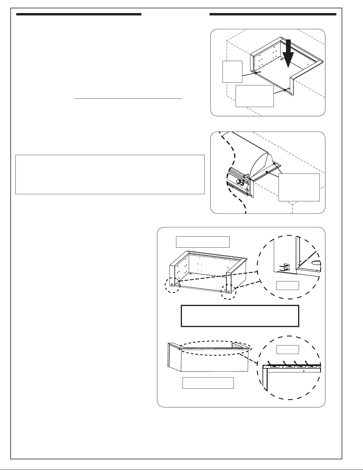
INSTALLATION
1. Install the insulating liner as shown in Fig. 4-1.
• If installing on a countertop with an irregular/textured
surface, a bead of silicone sealer rated for 400° or higher
may be needed to protect from the elements.
• The insulating liner has knock-out holes (two at the front,
and two at the rear) for electrical feeds (if applicable), and
the gas feed.
Note: If possible, use the front hole for electrical feeds. See
Fig. 4-3.
2. Install your grill per your grill owner's manual.
Important: Do not allow the grill hanger to come in contact
with the countertop or any combustible surface
see Fig. 4-2).
(
VENTILATION PORTS LOCATED AT THE FRONT AND
REAR OF THE GRILL INSULATING LINER SHOULD
NEVER BE BLOCKED. KEEP CLEAR FOR PROPER
VENTILATION OF THE UNIT. See Fig. 4-3.
11/2"
hole
(gas)
11/2"
electrical hole
(if applicable)
Fig. 4-1 Install insulating liner
Grill hanger
rests on
insulating liner
(sides and rear)
Fig. 4-2 Install grill into liner
(Front view of liner)
KEEP THESE VENTILATION PORTS
CLEAR AT ALL TIMES
(Rear view of liner)
(Ports below
rear-hanger)
Front
Rear
REV 0 - 1506180940
Fig. 4-3 Keep ventilation ports clear
4
L-C2-461
 Loading...