

Page 1
BEVERAGE CENTER
INSTALLATION
INSTRUCTIONS & OWNER’S
MANUAL
INSTALLER: Leave these instructions with consumer.
CONSUMER: Retain for future reference.
IMPORTANT: READ ALL INSTRUCTIONS CAREFULLY BEFORE STARTING INSTALLATION OR USE.
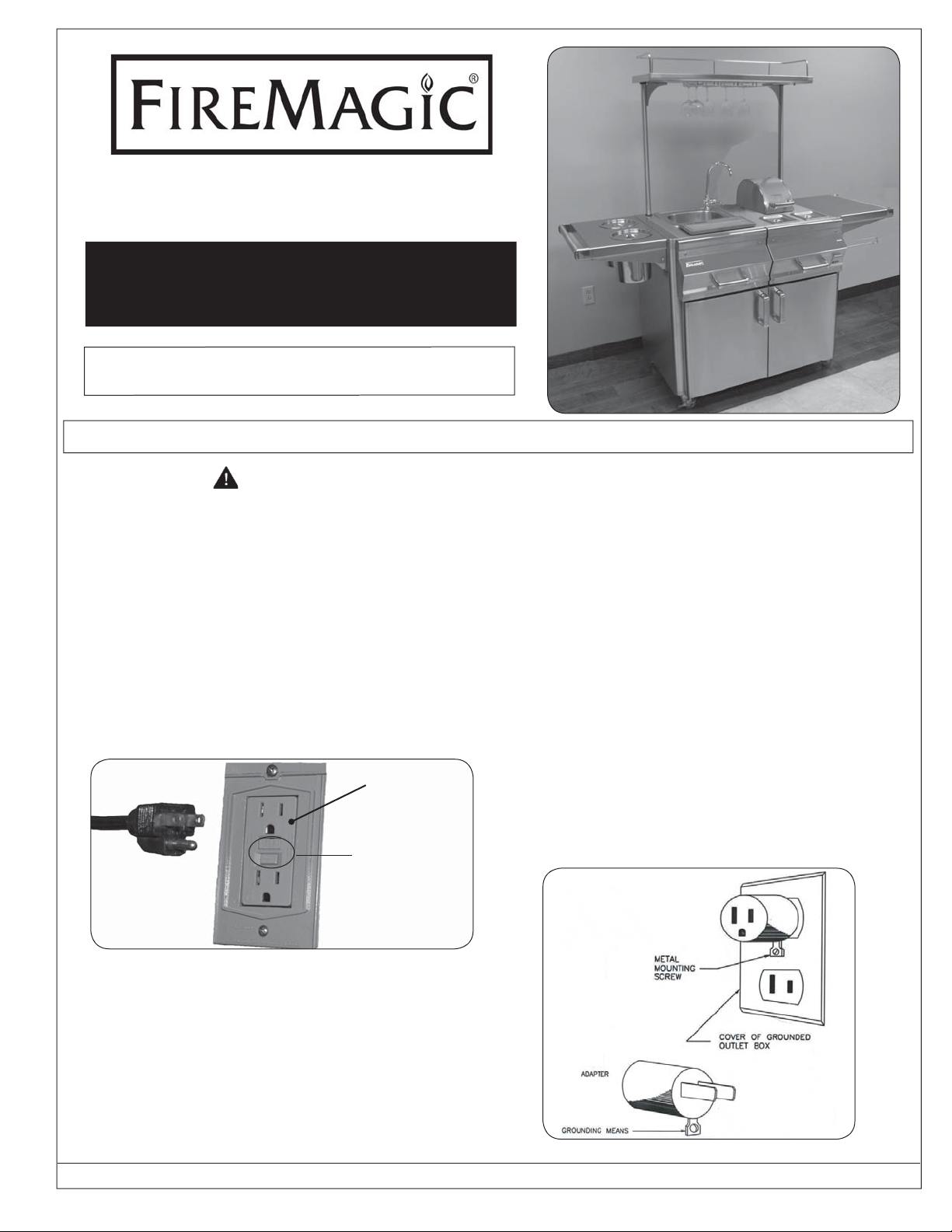
WARNING
Electrical Grounding Instructions
This electrical appliance is equipped with
a three-pronged (grounding) plug for
your protection against shock hazard and
should be plugged directly into a properly
grounded three-prong GFI protected
receptacle. Do not cut or remove the
grounding prong from the plug.
Do not operate any appliance with a
damaged cord or plug, after an appliance
GFI
receptacle
Test and
Grounding
plug
reset
switches
Fig. 1-1
ELECTRICAL GROUNDING
To protect from electrical shock, this
appliance must be grounded while in use.
Two-pronged outlets may be grounded by
use of an adapter as shown in Fig. 1-2.
The grounding tab extending from the
adapter must be connected to a permanent
ground.
If an extension cord is used, it must be a
three-pronged cord listed for outdoor use.
These cords are identifi ed by the marking:
"Suitable for use with outdoor appliances;
store indoors while not in use." The cord
must be rated at or above the rating of
this appliance as specifi ed on the rating
plate.
Grounding methods
malfunction, or after the appliance has
been dropped or damaged. Return the
appliance to your dealer or authorized
service facility for inspection, repair, or
electrical/mechanical adjustment.
ROBERT H. PETERSON CO. • 14724 East Proctor Avenue • City of Industry, CA 91746
Rev 4 - 0901121556
Fig. 1-2
1
NO. L-C2-27409
Page 2
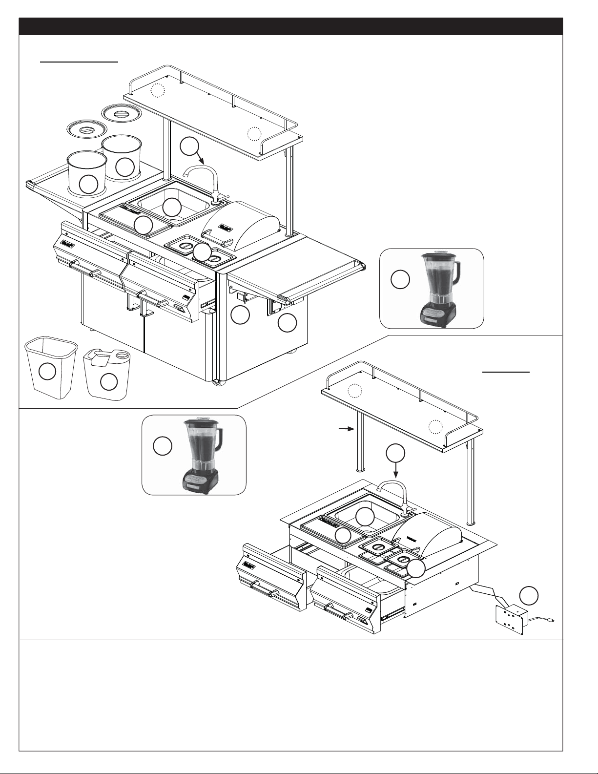
PARTS LIST
Stand-alone
6
Item
No.
8
8
Description Qty.
1. Sink 1
2. Faucet 1
3. Blender kit 1
4. Cutting board 1
5. Condiment holder with lid 2
2
6. Food/Beverage holder with lid 2
6
1
4
7. Waste water container 1
8. Overhead lights 2
9. Paper towel rack 1
10. GFI / receptacle 1
11. Waste basket 1
5
3
Blender kit
(packed
9
separately)
10
11
7
Built-In
7
OPTIONAL
7
Blender kit (packed
separately)
Item
No.
Description Qty.
1. Sink 1
3
upper shelf
(non-retrofi ttable)
2
1
4
2. Faucet 1
3. Blender kit 1
4. Cutting board 1
5. Condiment holder 2
6. Electrical junction box 1
7. Overhead lights (if equipped) 2
The beverage center is available in both built-in and stand-alone models.
Built-in and stand-alone models come with a sink, cutting board, blender, an equipment drawer,
drawer-front bottle opener, and a clean ice drawer. The unit is also topped with an upper shelf
(optional on built-ins) with a lighted covering that sports a wine glass rack and additional upper
storage area.
Stand-alone models come with shelves, a storage area containing two full-sized ice trays and two
wine holders for cooling beverages, a wheeled cart, side-folding paper-towel rack, and built-in
transformer box.
Rev 4 - 0901121556
2
5
6
NO. L-C2-27409
Page 3
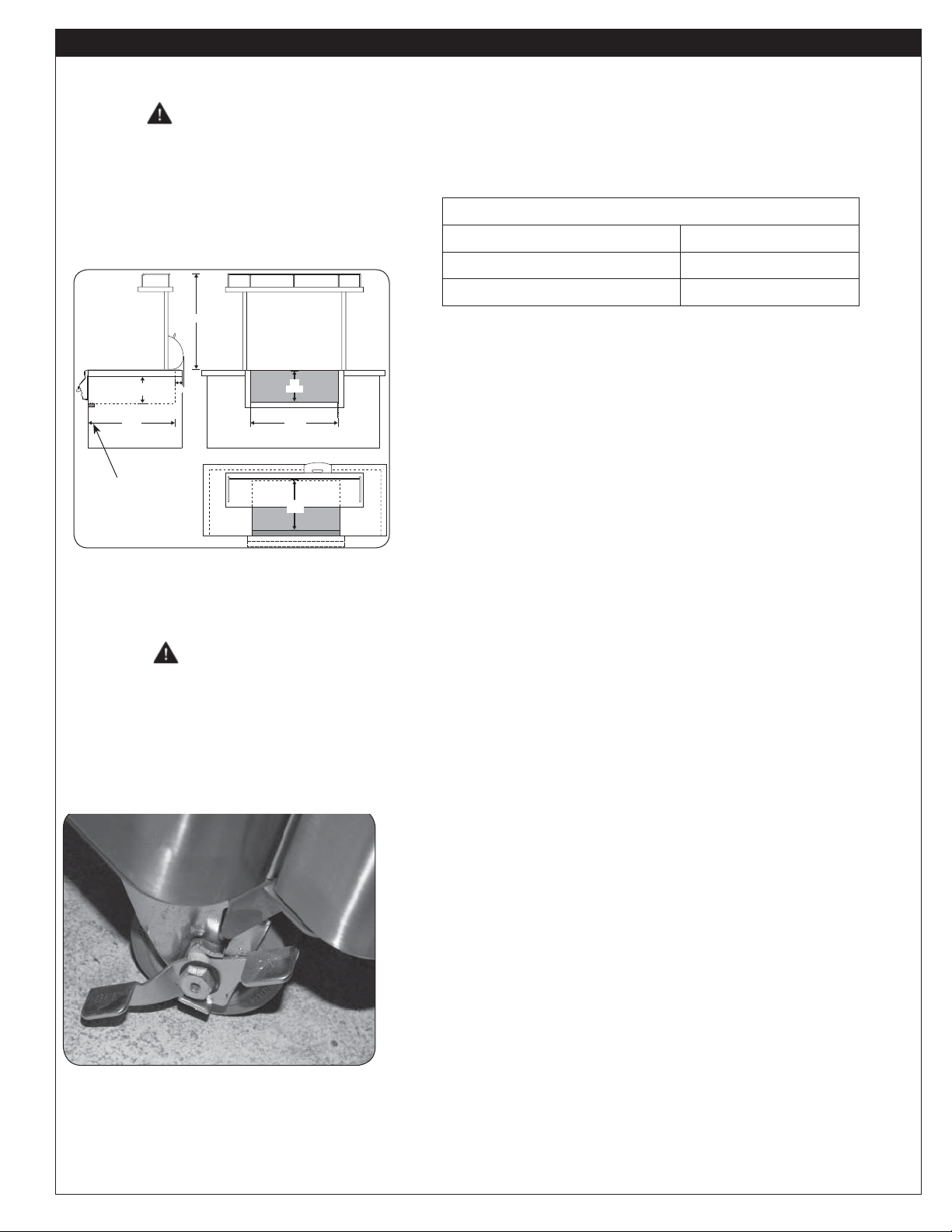
INSTALLATION
4"
23-1/2"
12"
23 1/2"
Depth
Height
12"
Height
Depth
34"
Side view
Top view
Front view
36-1/2"
Width
Built-in units
WARNING
Have all electrical work
performed by a licensed
professional electrician.
Counter cut-out dimensions for built-in
(shown here with optional upper shelf)
Front
support
Fig. 3-1
Prepare a cut-out in the countertop as specifi ed in
Table 1 and shown in Fig. 3-1. Note additional
clearance required to the rear for the blender cover
to open fully.
Counter Cut-out Dimensions (Table 1)
Counter Opening Height*
Counter Opening Width*
Counter Opening Depth*
12"
3623-
3/4
1/2
"
"
Install a listed, grounded 110-volt GFI receptacle
beneath the countertop within 5 feet of the blender
base so that the blender can be plugged into it.
Install the electrical junction box near the GFI
receptacle so that it can be plugged in the receptacle.
The wires from the box are already connected to the
beverage center.
The transformer box must be put inside the enclosure
before the beverage center is installed.
WARNING
This appliance must be
connected to a grounded
electrical source.
Caster in locked position (stand-alone only)
Fig. 3-2
After the enclosure cut-out and the electrical and
plumbing hookups are prepared, place the beverage
center into the cut-out. Keep all electrical wires from
being pinched between the beverage center and the
enclosure.
The beverage center will rest on the countertop by
its stainless-steel hanger and on the front support
shown in Fig. 3-1 underneath the face.
Silicon sealant may be applied around the top edge
of the countertop cut-out to create a barrier between
the housing and countertop capable of keeping out
fl uids. Do not use silicon between the blender base
and the stainless-steel housing, as the base must be
removable for cleaning and maintenance.
Stand-alone units
Locate the unit on a fl at, level surface near desired
electrical and water lines. To lock a caster press down
on the side of the lever with the word "OFF" stamped
on it until it stops and does not turn (see Fig. 3-2).
Repeat for all casters. For the stand-alone beverage
center, plug the end of an extension cord matching
the requirements on the cover into the left-most
electrical receptacle on the right side.
Rev 4 - 0901121556
3
NO. L-C2-27409
Page 4

Drain sink to container or drain line
Drain
spout
Faucet
base
Drain
clean-out
Knock-
out
Waste
water
container
Stand-alone water hookup
Fig. 4-1
Waste water
Female hose
knock-out
connector
Fig. 4-2
Electrical connectors (stand-alone only)
ASSEMBLY
Plumb or set up waste water disposal
The sink comes with a plastic trap and drainpipe
extending just below the sink (see Fig. 4-1).
A waste water container may be placed under the
sink. It must then be periodically checked and
emptied when full.
Alternately, a permanent waste water drain may
be plumbed from under the sink out through the
knock-out in the rear left (stand-alone only) or the
enclosure (built-in only) to an appropriate drain.
Observe all locally applicable codes. If required,
remove the knock-out (stand-alone only) by striking
it forcefully in the center with a mallet or other
appropriate tool. Observe all locally applicable
codes.
Attach a water source (stand-alone)
The sink comes pre-installed and is plumbed so that
a garden hose or other pressurized water-supply
line can be connected to the female hose connector
centered in the lower end of the back of the unit
(see Fig. 4-2). The connector on the garden hose
must be clean and free of foreign material. Screw
the end of the hose onto the female hose connector.
Blender placement (side view)
Blender
Cord into cutout
depressions
Fig. 4-3
Domed
lid
plastic plug
Fig. 4-4
Attach a water source (built-in)
Plumb a water line through the inside of the
enclosure to the
1
/2” NPS connector attached to the
faucet.
Connect the stand-alone to electrical power
To use the electrical outlets, blender, and electrical
sockets (stand-alone only), the beverage center must
be connected to electrical power. This is performed by
plugging in a grounded electrical extension cord rated
for outdoor use.
Plug the male end of the extension cord into an active
electrical outlet and the female end into the left-most
electrical connector on the right side of the unit (Fig.
4-3). Other electrical devices may be plugged into
the electrical outlets on the right of the line-power
hookup.
Rev 4 - 0901121556
4
NO. L-C2-27409
Page 5

ASSEMBLY (Continued)
WARNING
Do not use blender in
rain or wet conditions.
Plug-in blender inside left stand-alone wall
Fig. 5-1
Drawer slider
Inner wall
Match cutting board feet to holes
Receptacle
Outer wall
Fig. 5-2
Cutting board
Place blender in blender mounting
Open the domed lid attached to the right back of
the countertop. Unpack the blender and read the
instructions.
Attach the plastic plug to the three-pronged electrical
cord. Feed the cord through the cutout that is located
on top of the counter in front of the domed lid. Be
sure to snap the plastic plug in place. (See Fig.
4-4 on page 4). From there, plug the cord into the
nearest grounded electrical outlet.
In the stand-alone unit, the nearest outlet is located
in the right-side wall. Lower the cord towards the
right-side wall and then open the doors and remove
the middle right-side drawer. Locate the blender cord
through the opening on the right above the receptacle
(Fig. 5-1) and plug it in.
Place the blender base carefully onto the blender feet
depressions that are located on top of the counter in
front of the domed lid.
See blender instructions for additional details on
blender installation, use, and maintenance. Test the
blender and electrical connection by applying and
turning off power without the container in place.
Stainless-steel
counter
Slide the containers into countertop
Fig. 5-3
Slide the holders into the shelf-top holes
Fig. 5-4
Place the cutting board
Unpack the wood cutting board and place the four
(4) rubber feet into the four (4) depressions on top
of the counter in front of the sink (Fig. 5-2). The
cutting board is designed to stay fi rmly in place while
in use and yet be easy to remove, clean, and store as
needed.
Place stainless-steel bottle/food holders (stand-alone
only) and condiment storage containers (built-in and
stand-alone)
Unpack the stainless-steel bottle/food holders and
condiment storage containers with lids.
Place the condiment storage containers in the
rectangular holes in the top of the counter in front of
the blender. Cover them with the rectangular lids (Fig.
5-3).
On the stand-alone only, lift the left shelf and lock it
into place following the instructions below, then insert
the two stainless-steel bottle holders into the circular
holes in the top of the shelf (see Fig. 5-4).
Rev 4 - 0901121556
Alternately, a tap for draught beverages could be
installed/inserted through the rear circular hole.
5
NO. L-C2-27409
Page 6

ASSEMBLY (continued)
Paper towel holder (stand-alone only)
Fig. 6-1
Caster in locked position (stand-alone only)
Install paper towel holder (stand-alone only)
Unpack the paper-towel holder hanger, squeeze the
open ends together slightly, and insert them into the
mounting bracket on the front right (Fig. 6-1).
Next, release the hanger so that the ends poke
out through the holes in the top and bottom of the
mount.
OPERATION
(Un)locking casters (stand-alone only)
To lock a caster press down on the side of the lever
with the word "OFF" stamped on it until it stops and
the caster will not turn. To unlock, press down on the
side stamped "ON."
Fig. 6-2
Using the light switch
Fig. 6-3
Magnetic bottle opener (right drawer)
Turning the light on and off (if equipped)
Note: The beverage center must be plugged in to a 110V
AC power source.
Locate the button underneath the right side of the
light panel. Press the button to turn on and off the
two halogen lights underneath the rack.
Using magnetic bottle opener
A magnetic bottle opener is located on the right side
drawer. To use simply insert the top of the bottle as
shown in Fig. 6-4 and pull the bottom of the bottle
downward until the cap is removed. The cap will then
stick to the magnet instead of falling to the ground.
Remove the cap from the magnet and discard.
Fig. 6-4
Rev 4 - 0901121556
6
NO. L-C2-27409
Page 7

Left storage drawer
Fig. 7-1
Removing clean ice storage drain plug
Fig. 7-2
Removing basin
OPERATION (continued)
Doors and Drawers
The left top drawer (Fig. 7-1) is for tool/utensil
storage. The blender container and other such items
may be stored effectively in this drawer.
The right top drawer is for storage of clean ice. Open
the drawer, make sure the drain plug is in place (Fig.
7-2), and pour the ice into the basin. Close the
drawer to protect the ice from wind and debris and
to keep it shaded. Remove the drain plug to allow
melted ice to drain. Wipe out or clean as needed.
The two basins inside the door on the right of the
beverage center (stand-alone only) are for iced
beverage storage. The basins may be removed to
dump used ice (
To remove a drawer; pull it completely out. Release
the drawer from the drawer slides by pressing the
black lever down on the right side, and up on the left
side
(Fig 7-4). Then lift upward and outward on the
drawer until it comes free of the runners.
Fig. 7-3)
.
Fig. 7-3
Release drawer slider prior to removal
Fig. 7-4
Glass storage racks under top (if equipped)
Fig. 7-5
Waste basket (Stand-alone only)
To re-attach a drawer; extend the drawer slides
completely and align the drawer into the slides, pushing
the drawer closed. Open the drawer to verify that it has
locked in place.
Both stand-alone doors are held in place magnetically
when closed.
Wine glass retainer (if equipped)
Place wine glasses as shown in Fig. 7-5. Do not force.
WARNING
Total weight on the upper storage
shelf must not exceed 35 lbs.
Using the waste basket (stand-alone only)
The rubber waste basket fi ts into the stainless-steel
loop attached to the inside of the left door (Fig. 7-6).
Rev 4 - 0901121556
Fig. 7-6
7
NO. L-C2-27409
Page 8

OPERATION (Cont.)
CAUTION
Do NOT place fi ngers near
hinge when closing.
Lower left shelf (holders removed)
Bottle
holder
holes
Fig. 8-1
CAUTION
The paper-towel holder must
be folded back against the unit
before lowering the folding shelf
(see above). Failure to do so
could result in damage to the
beverage center.
To lower or raise shelves (stand-alone only)
A. To lower the shelf, grasp the shelf and lift from
the hinges (Fig. 8-1).
B. To raise the shelf, grasp the shelf aw ay from the
hinge and lift upward until the hinge comes out
of the retainer slot. Then rotate the shelf upward
until it is completely horizontal and drop the hinge
back into the retaining slot, keeping fi ngers and
other objects away from the hinges.
Adjusting and refi lling the paper-towel holder
To use the paper-towel holder:
1. Make sure the drop down shelf is upright.
2. Grasp the rounded end of the paper towel holder
fi rmly (without compressing it) and pull it away
from the side of the unit so that it rotates toward
the front of the unit and locks into the extended
position.
3. Slide a roll of paper towels over the rounded end
of the paper-towel holder until the entire roll is
on the holder (Fig. 8-2).
When not in use, the rack may be folded back out
of the way by fi rmly grasping the rounded end of
the holder and rotating it back into position against
the wall of the unit.
Paper-towel holder (stand-alone only)
Fig. 8-2
Important:
Wine bottle/food containers
must be removed prior to
collapsing the left-hand shelf.
Rev 4 - 0901121556
8
NO. L-C2-27409
Page 9

Cleaning and Maintenance
Fig. 9-1
Fig. 9-2
Changing the bulbs (if equipped)
WARNING
To protect from potentially sharp sheet metal and glass, wear
gloves and safety glasses during this procedure.
1. Turn off all electrical sources.
Important: Place one hand directly below the glass lens
and prepare to catch it when it is detached.
2. Carefully insert your fi ngernail or a thin plastic
spatula between the glass lens and the stainless
steel, and gently pry the glass lens out (Fig. 9-
1). Catch the lens (Fig. 9-2) and set it safely
aside.
Note: You may wish to take this opportunity to clean and dry
the lens with a standard household window cleaner.
Dry completely before reattaching.
3. Wearing a pair of gloves, reach into the fi xture,
gently grab the bulb (Fig. 9-3), and pull it straight
down and out of the fi xture so that the two pins at
the base of the bulb come all the way out.
Fig. 9-3
Fig. 9-4
Important: Bulb is halogen. DO NOT TOUCH with bare
hands. Oils from hands drastically reduce bulb
life.
Note: It may be helpful to rock the bulb gently backward and
forward while pulling it out.
4. Insert the new bulb into the socket so that both pins
slide all the way into the two holes in the bottom
of the socket and the bulb remains in place after
being released.
5. Place the lens back into the fi xture opening with the
curved cut-out toward the back and snap it fi rmly
but gently back into place.
Beverage Center Cover
To reduce the need for cleaning, cover your beverage
center between uses with the Fire-Magic® custom
cover (Fig. 9-4).
Always remove items from the upper storage area
before covering.
Rev 4 - 0901121556
Uncover the beverage center with care. Always lift
or slide the cover gently off the upper storage rack.
Never pull sideways, as the rack may be damaged or
loosened.
9
NO. L-C2-27409
Page 10

CLEANING AND MAINTENANCE (continued)
Always wipe with grain
Fig. 10-1
Care and cleaning
Clean up spills as required with a damp cloth or
sponge or a non-abrasive low-acid cleaning solution.
For heavy cleaning, clean with a quality stainlesssteel cleaner as necessary. Follow the directions on
the cleaner. Always wipe in the direction of the grain
(see Fig. 10-1).
You may fi nd it useful to fi rst remove the blender
from the stainless-steel housing (see the section in
this instruction, Place blender in blender mounting, or
separate blender instructions).
In a humid environment, due to the nature of
stainless steel, iron oxide deposits may appear. Such
deposits are removable using stainless-steel cleaner.
Store the blender container in a drawer and close the
stainless-steel lid over the blender base to protect it
when not in use.
Cover your beverage center when not in use (see
Beverage Center Cover section on previous page).
WARRANTY
LIFETIME WARRANTY - Fire Magic® cast stainless-steel burners, stainless-steel rod cooking grids, and stainless-steel housings are
warranted for as long as you own your Fire Magic® grill.
FIFTEEN-YEAR WARRANTY - Fire Magic® cast brass burners, brass valves, backburner assemblies (except ignition parts), and
manifold assemblies are warranted for 15 years from the date of purchase of your Fire Magic® grill.
THREE-YEAR WARRANTY - Fire Magic® sideburners and all other Fire Magic® grill components (except ignition and electronic
parts) are warranted for three (3) years from the date of purchase of your Fire Magic
Fire Magic
warranted for one (1) year from date of purchase.
This warranty applies to the original purchaser and to single family residential use only. It commences from date of purchase, and is valid only with
proof of purchase.
This warranty does not cover parts becoming defective through misuse, accidental damage, electrical damage, improper handling, storage, and/or
installation. Product must be installed (and gas must be connected) as specifi ed in the instructions or operator’s manual, by a qualifi ed professional
installer. Accessories, parts, valves, remotes, etc., when used must be Peterson Co. product.
This warranty does not apply to rust, corrosion, oxidation, or discoloration, unless the affected component becomes inoperable. It does not cover
labor or labor-related charges.
This warranty specifi cally excludes liability for indirect, incidental, or consequential damages. Some states do not allow the exclusion or limitation of
incidental or consequential damages, so the above exclusion may not apply to you. This warranty gives you specifi ed legal rights, and you may have
other rights that may vary from state to state.
For additional information regarding this warranty, or to place a warranty claim, contact the R.H. Peterson dealer where the product was purchased.
®
ignition systems (excluding batteries), electronic components (including lights and thermometers), and accessories are
PLEASE KEEP A COPY OF YOUR SALES SLIP FOR PROOF OF PURCHASE
®
grill.
TO REGISTER YOUR PRODUCT ONLINE GO TO: WWW.RHPETERSON.COM,
AND CLICK ON PRODUCT REGISTRATION. THANK YOU FOR YOUR PURCHASE.
Rev 4 - 0901121556
10
NO. L-C2-27409
 Loading...