

Page 1
®
PRODUCT SPECIFICATIONS
INFORMATION FOR BUILT IN AND STAND ALONE GRILLS, DOORS AND DRAWERS
| PRODUCT SP ECIF ICATIO NS 2014
®
FIRE MAGIC
Page 2
A430i / 530i
33830-SW/43830-SW
53830-SW
†
½
32
25
½
½
½
A430i - 19
A530i - 23
½
A540i
- 19
A660i
- 23
½
14
½
21
30
15
14
21
30
21
31
13
30
21
31
13
20
½
12
12
12
Warming Drawer
33930S /43930S
53930S
Double Doors
33830-S /43830-S
*
53830-S
Masonry Drawer
33930S-12 /43930S-12
53930S-12
Double Doors w/ Dual
Drawers & Tank Tray
33920-SR/43920-SR
53920-SR
Single Access Door
/43934S
53934S
Double Door Access
33820-SL /43820-SL
53820-SL
Single Access Door
w/ Dual Drawers
33917-SR
/
43917-SR
53917-SR
Single Access Door
33820-TSL /43820-TSL
Single Access Door
CHARCOAL 12-S1
DELUXE 11-S
CHARCOAL 14-S1
24
¾
32
¼
26
¼
19
¾
19
¾
17
12
12
12
20
½
20
½
20
½
½
½
19
12
COMBO GRILL A830i
50
25
17
½
33924-SR/43924-SR
53924-SR
Single Access Door
53938S
(a)
¼
¾
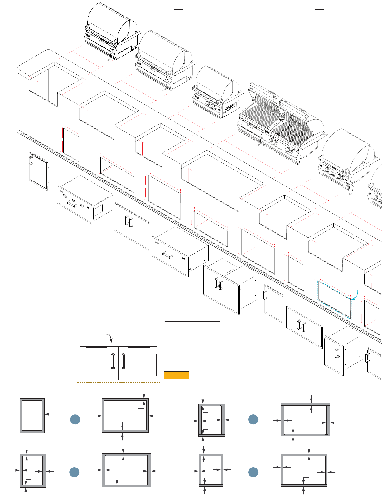
ALL DIMENSIONS ARE IN INCHES
AVAILABLE WITH LEFT
DOOR HINGE (-SL)
* 53830-S Masonry Drawer (14½ x 32¼ x 22)
† 53830-SW Warming Drawer (14½ x 32¼ x 22)
(a) 53938S DOUBLE ACCESS DOORS
is aesthetically designed to t under the A790i/E790i
A. LEGACY (2 SERIES)
B. SELECT (3 SERIES)
C. PREMIUM (4 SERIES)
D. FLUSH MOUNTED (5 SERIES)
SINGLE DOOR DOUBLE DOOR
Cutout Dimensions 16"x 39"
Door/Drawer
Frame Outline
A430i / C430i
/ A530i
AVAILABLE WITH RIGHT
DOOR HINGE (-SR)
DETAIL 2
TYPICAL
AVAILABLE WITH LEFT
DOOR HINGE (-SL)
AVAILABLE w/ LOUVERS (-12T)
33920S-22 / 43920S-22
53920S-22
DOUBLE DOORS w/ 2 DUAL
DRAWERS
DETAIL 2
AVAILABLE WITH LEFT
DOOR HINGE (-SL)
1.75”
1.75”
1.75”
1.75”
2.25”
2.25”
1.5”
1.75”
(Around)
1.75”
2”
1.75”
2.25”
1.5” 1.5”
A
2.25”
B
1.75”
1.75”
1.5”
1.5”
2.25”
1.5”
1.75”
2.25”
C
1.75”
1.5”
D
1.5”
1.5”
2.25”
1.5”
Page 3
E1060i
A790i/E790i
E660i
A540i / A660i
50
E790i - 37
A790i - 37
¾
31
¼
26
¼
12
23
½
23
½
23
½
14
½
14
½
15
¾
14
½
21
24
½
18
14
½
5
¼
12
33820-TSL /43820-TSL
53820-TSL
Single Access Door
w/ Tank Tray
33801/43801
53801
Single Enclosed
Drawer
33802/43802
53802
Double Enclosed Drawer
33803/43803
53803
Triple Enclosed Drawer
33914-SL /43914-SL
53914-SL
Single Access Door
15
20
½
20
½
20
½
20
½
20
½
A540i / C540i
/ A660i
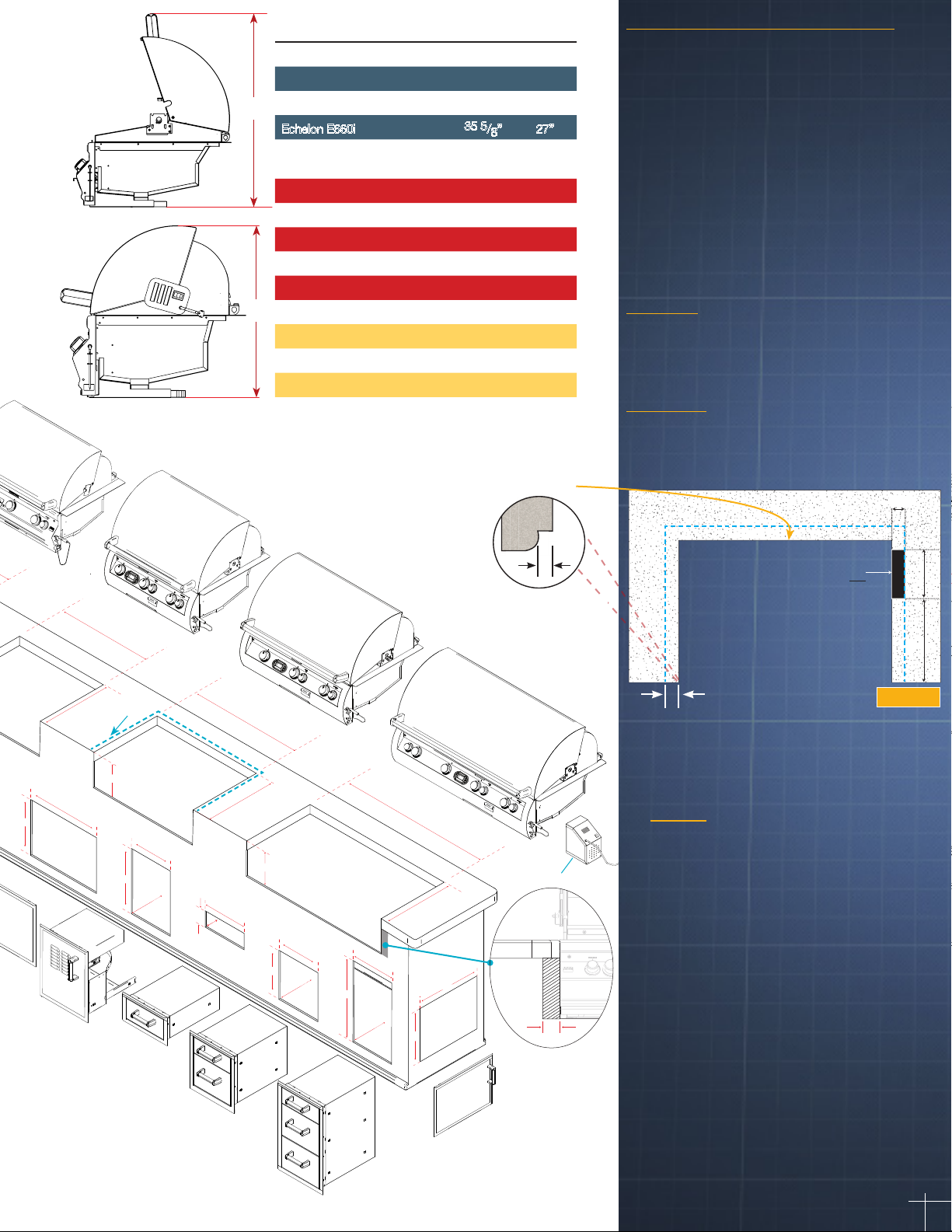
DESCRIPTION HOOD
OPEN
A B
Echelon E1060i 35 5/8” 27”
Echelon E790i 35 5/8” 27”
A
Echelon E660i
35 5
A u r o ra A 8 3 0 i 35 5/8” 27”
Aurora 790i 35 5/8” 27”
Aurora A660i 35 5/8” 27”
Aurora A540i 32 1/4” 25 1/4”
Aurora A530i 35 5/8” 27”
Aurora A430i 32 1/4” 25 1/4”
B
Deluxe 11-S 29 3/4” 25 1/8”
32” Gourmet Charcoal 14-S1 31 3/4” 26 1/2”
26” Gourmet Charcoal 12-S1 31 3/4” 26 1/2”
Grill Hanger Outline
HOOD
CLOSED
/8” 27”
OUTDOOR KITCHEN CONSIDERATIONS
• Carefully consider grill size & accessories needed
• Combustible construction requires insulating liner
• Select Natural or Propane (LP gas)
• Determine total gas consumption for supply line size
• Access required to gas connections and shut o valve
• Plan location of propane tank away from grill and appliances
• Always refer to the installation and operating instructions of your
Fire Magic® grill and/or accessories for installation guidelines &
safety warnings before starting your project
• Always check all gas connections for leaks
• Provide ventilation in island for gas vapors. Allow at least
four ventilation openings (two at oor level and two 16” above oor
10 in² each) at opposing ends/sides
LOCATION
• Identify outdoor area where grill will be installed
• Determine the utilities needed (gas, water, electricity, drainage etc.)
• Consider element exposure (sun, wind direction*, weather etc.)
MATERIALS
• Foundation- concrete
• Base- brick, stone, stucco, concrete
• Counter top- tile, granite, marble, concrete
1 ¼”
AVAILABLE WITH RIGHT
DOOR HINGE (-TSR)
DETAIL 1
TYPICAL
FOR BULL NOSE COUNTER TOP
Allow the grill face to sit flush
when installed.
?,_[YHJ\[V\[MVY
7V^LY/VVK653@
COUNTER TOP
X
10”
11”
TOP VIEW
SEE NOTE 6
AVAILABLE WITH RIGHT
3" clearance required (on
both sides) for access
to battery compartment
when using material that
extends out from island
surface.
DOOR HINGE (-SR)
3"
Grill hanger varies in width (2½"-3")
depending on the size & configuration
of the grill.
Notes
1. There is a hanger on three sides of each grill. You must
allow clearance for the hanger (SEE DETAIL 1).
2. The control panel (face) of the grill is wider than the
cutout width. This conceals the cutout space on the left &
right hand sides.
3. Clearance of 10” on each side of the oven is
recommended for unrestricted operation of lid and
rotisserie and at least 3” at the rear ange for ease of
maintenance and proper operation. (18” from combustible
surroundings on each side and rear is required)
4. See specic model cutout plan for units equipped with
motorized hood.
5. Insulating liners must be used & are available for
combustible surrounds (See page 6).
6. The rotisserie motor on all models is located on the right
side of the grill. Optional Reverse Brackets are available
to mount rotisserie motor on opposite side. ONLY units
ordered with back burner option come with rotisserie kit
and brackets.
DETAIL 1
3
Page 4

REGAL I COUNTERTOP
22
CLASSIC DOUBLE DOORS
signifies BLACK POWDER COATED
20
1
34
3590A & 3590-DR
REFRIGERATOR
/DL
53825-T
TRASH CONTAINER
∞ Proper operation requires a oor drain
within 5ft. of the ice maker.
† The new Cut & Clean Combo can
also be dropped into the 3280
Single Sideburner cutout.
14
8
¾
21
LARGE CAPACITY
¼
14
24
3593 ∞
ICE MAKER
4
¾
8
¼
¾
12
20
23920-1T(-S)*
TANK DOOR LOUVERED
w/ PULL OUT TRAY
BLENDER
3284A
8
¾
16
34
4
½
27
½
SIDEBURNER
6
¼
16
8¾
14
14 ½
½
20
½
20
23820-S
DUAL DRAWER
CABINET
SINGLE
3280
Cut & Clean Combo
¼
15
14
½
20
23918(-S)*
STORAGE DOOR
15
14
20
53816
STEEL SINK
½
½
STAINLESS
3587
24½
19¼
½
18
23920(-S)*
STORAGE DOOR
12
ALL DIMENSIONS ARE IN INCHES
DELUXE CLASSIC
COUNTERTOP
31-S
12
DELUXE GOURMET
COUNTERTOP
3C-S
14
29
½
½
20
41
½
½
16
½
14½
20
½
14½
27¾
17
12
½
20½
24
½
18½
12
½
34-S
18
14
¾
22
12
20½
½
14
CLASSIC CHARCOAL GRILLS
DESCRIPTION
32” Lift-A-Fire
Charcoal 3334
24” Lift-A-Fire
Charcoal 3339
31” Firemaster 3324
24” Firemaster 3329
OPENING REQUIRED
WIDTH DEPTH HEIGHT
32 1/4” 19 3/4” 12”
24 3/4” 17 3/4” 12”
31 1/4” 21 1/4” 12”
24 1/4” 19 1/4” 12”
ACCESSORIES CUT-OUT DIMENSIONS
23920-1(-S)*
STORAGE DOOR
25914(-S)*
DRAWER & L.P
DOOR ASSEMBLY
12”
8”
53812
PAPER TOWEL HOLDER
23924(-S)*
STORAGE DOOR
9 ¼”
23912(-S)*
STORAGE DOOR
w/o (-S)
23914(-S)*
STORAGE DOOR
STORAGE DOOR
(-S) signifies STAINLESS STEEL
*
17
23917(-S)*
½
Page 5

3"
A430 Pedestal Dimensions
A430s-2E1N-P6
26"
50"
57"
56"
25"
Notes
1. There is a hanger on three sides of the grill (SEE DETAIL 3).
2. The control panel (face) of the accessories is wider than the cutout
width This conceals the cutout space on the left & right hand sides.
3. Clearance of 10” on each side, and 3” at the rear of the oven is
recommended for unrestricted operation of accessories. (18” from
combustible surroundings on each side and rear)
4. Insulating liners must be used and are available for combustible
surrounds. Double Side burner (3281), Single Side burner (3279-1)
and Drop-In Side burner (3280) do not require an insulating liner
(See page 6).
Accessory Hanger Outline
COUNTER TOP
TOP VIEW
SEARING STATION
32874-1 & 3287-1
12
17"
BAR CADDY
1D-S0
DOUBLE
SIDEBURNER
32814 & 3281
12
24.5"
FOR BULL NOSE COUNTER TOP
Allow the grill face to sit flush
when installed.
12
SINGLE
SIDEBURNER
32794-1 & 3279-1
14
¼
½
11
½
¾
22
DETAIL 3
12
TYPICAL
18
12
12
24½
14
DETAIL 4
TYPICAL
12
19
¾
½
11
POWER BURNER
19 SERIES
½
25
12
REFRESHMENT
CENTER
3596
12
DBL SEARING STATION
32884-1 & 3288-1
BEVERAGE CENTER
1D-SSA
12
DETAIL 3
Accessory hanger varies in width
(2”-2½” ALL AROUND) depending
on the size & configuration of the
accessory.
Door/Drawer
Frame Outline
½
20
23930-S
S
23930S-12
CLASSIC DOUBLE DOORS
W/ DUAL DRAWERS & TANK TRAY
30
12
30
23
½
21
½
20
23830-S
MASONRY DRAWER CABINET
12
¾
½
36
DETAIL 4
Door frame varies in width (1"-2"
ALL AROUND) depending on the
13
20
½
23
31
½
12
¾
3
3" clearance required (on
both sides) for access to
¾
battery compartment when
using material that extends
out from island surface.
size & configuration of the door
& drawer.
5
Page 6

BUILDING IN A COMBUSTIBLE ISLAND
INSULATING LINER MUST BE USED WHEN INSTALLING IN A COMBUSTIBLE ISLAND
Not used on Double Sideburner (3281), Single Sideburner (3279-1) or Drop-In Sideburner (3280)
GRILL CUT-OUT DIMENSIONS w/ INSULATING LINER
MODEL
Echelon E1060i
Echelon E790i
Echelon E660i
OPENING REQUIRED
WIDTH DEPTH HEIGHT
A B C
55” 26” 12”
42 1/8” 26” 12”
36 3/8” 26” 12”
C
A
GREEN: Support Hangers
RED: Heat Shield
BLUE: Combustible Material
C
A
Aurora A790i
Aurora A660i
B
Aurora A540i
Aurora A530i
Aurora A430i
Maintain proper clearance to combustible materials.
Notes:
1. A nominal 1/16” gap around the back and sides of the liner is recommended for ease of installation.
2. The counter top material may be placed up to the insulating liner on the back and sides.
3. A minimum of 100 sq. in. in air ventilation is required at cabinet face.
4. Cabinet face may be made of combustible material up to the front ange of the insulating liner.
To install and operate the Fire Magic® outdoor gas appliance,
please refer to the Installation and Operating instructions and
safety precautions shipped with the appliance.
42 1/8” 26” 12”
36 3/8” 26” 12”
36 3/4” 22 1/8” 12”
30 1/8” 26” 12”
30 1/8” 22 1/8” 12”
ACCESSORY & LEGACY CUT-OUT
DIMENSIONS w/ INSULATING LINER
B
MODEL
Deluxe
Power Burner
Searing Station
OPENING REQUIRED
WIDTH DEPTH HEIGHT
A B C
28 19 3/8” 12 1/4”
22 5/8” 20 3/4” 12”
18 3/8” 24 3/4” 11 5/8”
The information provided is for reference only. Detailed instructions are supplied with the insulation liner, unique to
the model selected. Read those instructions carefully and completely before starting installation of the liner.
6
Page 7

ECHELON STAND ALONE
C
D
A
B
Model # Series Top of Face
(A)
E1060 62 37" 53" 86 1/
E1060 51/71 37" 77 3/
E790 62 37" 40" 73 1/
E790 71 37" 58 3/
E660 62 37" 34 1/
E660 71 37"
Cart Base
(B)
4"
4"
4"
53"
Shelves Up
(C)
111" 60 5/
92" 60 5/
67 1/
86 1/
4"
4"
2"
4"
Oven Open
(D)
60 5/
8"
8"
60 5/
8"
8"
60 5/
8"
60 5/
8"
E
F
Max Outer
(E)
29 3/
4"
29 3/
4"
29 3/
4"
29 3/
4"
29 3/
4"
29 3/
4"
I
H
Cart Base
(F)
26" 52" 74 3/
26" 52" 99 1/
26" 52" 61 3/
26" 52" 80 1/
26" 52" 56" n/a
26" 52" 74 3/
Oven Closed
(G)
1-Up/1-Down
(H)
4"
2"
4"
2"
4"
Shelves Down
63 1/
G
(I)
n/a
88"
n/a
69"
4"
AURORA STAND ALONE
C
®
D
B
Model # Series Top of Face
(A)
A660s 61/62 37" 32 1/
A540s 61/62 37" 32 1/
A530s 61/62 37" 26" 55 3/
A430s 61/62 37" 26" 55 3/
A830s 61 37" 50 3/4"
Cart Base
(B)
2"
2"
A
Shelves Up
(C)
62 1/
4"
62 1/
4"
4"
4"
80 3/4"
E
F
Oven Open
(D)
60 5/
57 1/4" 25 3/
60 5/
57 1/4" 25 3/
57" 28 3/4"
8"
8"
Max Outer
(E)
29 3/
29 3/
4"
4"
4"
4"
I
H
Cart Base
(F)
26" 52" 52 1/
21 3/
26" 52" 46" 35 1/
21 3/
21 3/4"
4"
4"
Oven Closed
(G)
1-Up/1-Down
(H)
2"
50" 52 1/
2"
50" 46" 35 1/
50" 70 3/4"
Shelves Down
(I)
41 1/
2"
41 1/
2"
4"
4"
61 1/4"
G
7
Page 8

VENT HOOD
SPECIFICATION
36Ӡ
42”∆
48”^
60”*
18”
Electrical
Requirements
Fans
Power Consumption 1,010 watts
Models Available
120 volts, 60 hertz, 20 amp;
120 volts, 1200 CFM High
† 36-VH-6
∆ 42-VH-6
^ 48-VH-6
30”
* 60-VH-6
FIRE MAGIC® OUTDOOR GAS GRILL WARRANTY
LIFETIME WARRANTY
GFI outlet
Pressure Output
FIRE MAGIC® CAST STAINLESS STEEL BURNERS, STAINLESS STEEL ROD COOKING GRIDS, AND STAINLESS
STEEL HOUSINGS ARE WARRANTED FOR AS LONG AS YOU OWN YOUR FIRE MAGIC® GRILL.
TWENTY YEAR WARRANTY
CHOICE BURNERS ARE WARRANTED FOR TWENTY (20) YEARS.
FIFTEEN YEAR WARRANTY
FIRE MAGIC® BRASS VALVES, MANIFOLD ASSEMBLIES, INNER LINERS, AND BACKBURNER ASSEMBLIES (EXCEPT IGNITION
SYSTEMS) ARE WARRANTED FOR FIFTEEN (15) YEARS.
TEN YEAR WARRANTY
FIRE MAGIC® ELECTRIC GRILLS, ELECTRIC GRILL STAINLESS STEEL COOKING GRIDS, AND ELECTRIC GRILL STAINLESS
STEEL HOUSING ARE WARRANTED FOR TEN (10) YEARS.
FIVE YEAR WARRANTY
INFRARED BURNERS, FLAVORED GRILLS, CHARCOAL STAINLESS STEEL GRILLS, AND SMOKERS (EXCEPT FOR THE
CHARCOAL PAN, CHARCOAL GRID, WOOD PELLET SCREEN, THERMOMETER, AND ASH TRAY WHICH ARE WARRANTED FOR
ONE YEAR)
ARE WARRANTED FOR FIVE (5) YEARS
THREE YEAR WARRANTY
FIRE MAGIC® SIDEBURNERS AND ALL OTHER FIRE MAGIC® GRILL COMPONENTS (EXCEPT IGNITION SYSTEMS AND
ELECTRICAL PARTS) ARE WARRANTED FOR THREE (3) YEARS.
ONE YEAR WARRANTY
FIRE MAGIC® IGNITION SYSTEMS (EXCLUDING BATTERIES), ELECTRICAL COMPONENTS (INCLUDING LIGHTS AND
THERMOMETER), AND GRILL ACCESSORIES ARE WARRANTED FOR ONE (1) YEAR.
FIRE MAGIC® RESERVES THE RIGHT TO AMEND PRODUCT SPECIFICATIONS WITHOUT PRIOR NOTICE.
®
WWW.FIREMAGICGRILLS.COM
PHONE 800.332.3973
Rev.1 1405141235
L-C1-013
 Loading...