

Page 1

PN: 51127:C ECN 00-506
Fire Alarm Control Panel
MS-2410B &
MS-2410BE
Document #51127
11/7/00 Rev.
© 2000 Fire•Lite
C
Page 2

Fire Alarm System Limitations
While a fire alarm system may lower insurance
rates, it is not a substitute for fire insurance!
An automatic fire alarm system–typically made up of smoke
detectors, heat detectors, manual pull stations, audible warning devices, and a fire alarm control with remote notification
capability–can provide early warning of a developing fire.
Such a system, however, does not assure protection against
property damage or loss of life resulting from a fire.
The Manufacturer recommends that smoke and/or heat detectors be located throughout a protected premise following the
recommendations of the current edition of the National Fire
Protection Association Standard 72 (NFPA 72),
manufacturer's recommendations, State and local codes, and
the recommendations contained in the Guide for Proper Use
of System Smoke Detectors, which is made available at no
charge to all installing dealers. A study by the Federal Emergency Management Agency (an agency of the United States
government) indicated that smoke detectors may not go off in
as many as 35% of all fires. While fire alarm systems are designed to provide early warning against fire, they do not guarantee warning or protection against fire. A fire alarm system
may not provide timely or adequate warning, or simply may not
function, for a variety of reasons:
Smoke detectors may not sense fire where smoke cannot
reach the detectors such as in chimneys, in or behind walls, on
roofs, or on the other side of closed doors. Smoke detectors
also may not sense a fire on another level or floor of a building. A second-floor detector, for example, may not sense a
first-floor or basement fire.
Particles of combustion or "smoke" from a developing fire
may not reach the sensing chambers of smoke detectors because:
• Barriers such as closed or partially closed doors, walls, or
chimneys may inhibit particle or smoke flow.
• Smoke particles may become "cold," stratify, and not reach
the ceiling or upper walls where detectors are located.
• Smoke particles may be blown away from detectors by air
outlets.
• Smoke detectors may be drawn into air returns before
reaching the detector.
The amount of "smoke" present may be insufficient to alarm
smoke detectors. Smoke detectors are designed to alarm at
various levels of smoke density. If such density levels are not
created by a developing fire at the location of detectors, the
detectors will not go into alarm.
Smoke detectors, even when working properly, have sensing
limitations. Detectors that have photoelectronic sensing
chambers tend to detect smoldering fires better than flaming
fires, which have little visible smoke. Detectors that have ionizing-type sensing chambers tend to detect fast-flaming fires
better than smoldering fires. Because fires develop in different ways and are often unpredictable in their growth, neither
type of detector is necessarily best and a given type of detector may not provide adequate warning of a fire.
Smoke detectors cannot be expected to provide adequate
warning of fires caused by arson, children playing with
matches (especially in bedrooms), smoking in bed, and violent
explosions (caused by escaping gas, improper storage of
flammable materials, etc.).
Heat detectors do not sense particles of combustion and
alarm only when heat on their sensors increases at a predetermined rate or reaches a predetermined level. Rate-of-rise
heat detectors may be subject to reduced sensitivity over time.
For this reason, the rate-of-rise feature of each detector
should be tested at least once per year by a qualified fire protection specialist.
Heat detectors are designed to protect
property, not life.
IMPORTANT!
Smoke detectors must be installed in the
same room as the control panel and in rooms used by the system for the connection of alarm transmission wiring, communications, signaling, and/or power.
cated, a developing fire may damage the alarm system, crippling its ability to report a fire.
Audible warning devices such as bells may not alert people
if these devices are located on the other side of closed or
partly open doors or are located on another floor of a building.
Any warning device may fail to alert people with a disability or
those who have recently consumed drugs, alcohol or medication. Please note that:
• Strobes can, under certain circumstances, cause seizures
in people with conditions such as epilepsy.
• Studies have shown that certain people, even when they
hear a fire alarm signal, do not respond or comprehend the
meaning of the signal. It is the property owner's responsibility to conduct fire drills and other training exercise to make
people aware of fire alarm signals and instruct them on the
proper reaction to alarm signals.
• In rare instances, the sounding of a warning device can
cause temporary or permanent hearing loss.
A fire alarm system will not operate without any electrical
power. If AC power fails, the system will operate from standby
batteries only for a specified time and only if the batteries
have been properly maintained and replaced regularly.
Equipment used in the system may not be technically compatible with the control. It is essential to use only equipment
listed for service with your control panel.
Telephone lines needed to transmit alarm signals from a
premise to a central monitoring station may be out of service
or temporarily disabled. For added protection against telephone line failure, backup radio transmission systems are recommended.
The most common cause of fire alarm malfunction is inadequate maintenance. To keep the entire fire alarm system in
excellent working order, ongoing maintenance is required per
the manufacturer's recommendations, and UL and NFPA standards. At a minimum, the requirements of Chapter 7 of NFPA
72 shall be followed. Environments with large amounts of
dust, dirt or high air velocity require more frequent maintenance. A maintenance agreement should be arranged
through the local manufacturer's representative. Maintenance
should be scheduled monthly or as required by National and/
or local fire codes and should be performed by authorized professional fire alarm installers only. Adequate written records
of all inspections should be kept.
If detectors are not so lo-
LimWarLg.p65 01/10/2000
Page 3

Installation Precautions
Adherence to the following will aid in problem-free
installation with long-term reliability:
WARNING -
nected to the fire alarm control panel.
of power before servicing. Control unit and associated equipment may be damaged by removing and/or inserting cards,
modules, or interconnecting cables while the unit is energized.
Do not attempt to install, service, or operate this unit until this
manual is read and understood.
CAUTION -
Changes.
must be tested in accordance with NFPA 72 Chapter 7 after
any programming operation or change in site-specific software. Reacceptance testing is required after any change, addition or deletion of system components, or after any modification, repair or adjustment to system hardware or wiring.
All components, circuits, system operations, or software functions known to be affected by a change must be 100% tested.
In addition, to ensure that other operations are not inadvertently affected, at least 10% of initiating devices that are not
directly affected by the change, up to a maximum of 50 devices, must also be tested and proper system operation verified.
This system meets NFPA requirements for operation at
0-49° C/32-120° F
condensing) at 30° C/86° F. However, the useful life of the
system's standby batteries and the electronic components
may be adversely affected by extreme temperature ranges
and humidity. Therefore, it is recommended that this system
and all peripherals be installed in an environment with a nominal room temperature of 15-27° C/60-80° F.
Verify that wire sizes are adequate for all initiating and
indicating device loops. Most devices cannot tolerate more
than a 10% I.R. drop from the specified device voltage.
Several different sources of power can be con-
Disconnect all sources
System Reacceptance Test after Software
To ensure proper system operation, this product
and at a relative humidity of 85% RH (non-
Like all solid state electronic devices, this system may
operate erratically or can be damaged when subjected to lightning-induced transients. Although no system is completely
immune from lightning transients and interferences, proper
grounding will reduce susceptibility.
Overhead or outside
aerial wiring is not recommended, due to an increased susceptibility to nearby lightning strikes.
cal Services Department if any problems are anticipated or
encountered.
Disconnect AC power and batteries prior to removing or inserting circuit boards. Failure to do so can damage circuits.
Remove all electronic assemblies prior to any drilling, filing,
reaming, or punching of the enclosure. When possible, make
all cable entries from the sides or rear. Before making modifications, verify that they will not interfere with battery, transformer, and printed circuit board location.
Do not tighten screw terminals more than 9 in-lbs.
Over-tightening may damage threads, resulting in reduced
terminal contact pressure and difficulty with screw terminal
removal.
Though designed to last many years, system components
can fail at any time. This system contains static-sensitive
components. Always ground yourself with a proper wrist strap
before handling any circuits so that static charges are removed from the body. Use static-suppressive packaging
to protect electronic assemblies removed from the unit.
Follow the instructions in the installation, operating, and
programming manuals. These instructions must be followed
to avoid damage to the control panel and associated
equipment. FACP operation and reliability depend upon
proper installation by authorized personnel.
Consult with the Techni-
FCC Warning
WARNING: This equipment generates, uses, and can
radiate radio frequency energy and if not installed and
used in accordance with the instruction manual, may
cause interference to radio communications. It has
been tested and found to comply with the limits for class
A computing device pursuant to Subpart B of Part 15 of
FCC Rules, which is designed to provide reasonable
protection against such interference when operated in a
commercial environment. Operation of this equipment in
a residential area is likely to cause interference, in which
case the user will be required to correct the interference
at his own expense.
Canadian Requirements
This digital apparatus does not exceed the Class A
limits for radiation noise emissions from digital
apparatus set out in the Radio Interference Regulations
of the Canadian Department of Communications.
Le present appareil numerique n'emet pas de bruits
radioelectriques depassant les limites applicables aux
appareils numeriques de la classe A prescrites dans le
Reglement sur le brouillage radioelectrique edicte par le
ministere des Communications du Canada.
LimWarLg.p65 01/10/2000
Page 4

Notes
4
Document #51127 Rev.C 11/7/00 P/N 51127:C
Page 5

Table of Contents
CHAPTER 1: Product Description .........................................................................................................................9
1.1: Product Features..........................................................................................................................................9
1.2: Specifications ..............................................................................................................................................11
1.3: Controls and Indicators ...............................................................................................................................12
1.4: Circuits ........................................................................................................................................................13
1.5: Components ................................................................................................................................................13
1.6: Optional Modules........................................................................................................................................14
1.7: Optional Accessories...................................................................................................................................14
CHAPTER 2: Installation.........................................................................................................................................19
2.1: Mounting Options .......................................................................................................................................19
2.2: Backbox Mounting......................................................................................................................................19
2.3: Transformer Installation ..............................................................................................................................22
2.4: Main Circuit Board Installation...................................................................................................................23
2.5: Operating Power..........................................................................................................................................24
2.6: Input Circuits...............................................................................................................................................25
2.7: Output Circuits ............................................................................................................................................26
2.8: Power-limited Wiring Requirements...........................................................................................................27
2.9: Installation of Optional Modules with Remote Accessories.......................................................................28
CHAPTER 3: Programming Instructions...............................................................................................................34
3.1: Switch Functions .........................................................................................................................................34
3.2: Programmable Features and Options ..........................................................................................................35
3.3: Entering Program Mode..............................................................................................................................36
3.4: Programming Function................................................................................................................................37
3.4.1: Program Feature Selection................................................................................................................37
3.4.2: Programming Options.......................................................................................................................37
3.4.3: Programming Example .....................................................................................................................37
3.5: Program Features and Options ....................................................................................................................41
3.5.1: Program Features ..............................................................................................................................41
3.5.2: Programming Options.......................................................................................................................41
3.6: Default Programming Mode........................................................................................................................46
CHAPTER 4: Operating Instructions..................................................................................................................... 47
4.1: Switch Functions in Normal Mode .............................................................................................................47
4.2: Status LEDs.................................................................................................................................................48
4.3: Operation.....................................................................................................................................................49
4.3.1: Fire Alarm Response.........................................................................................................................50
4.3.2: Fire Alarm Restoral...........................................................................................................................50
4.3.3: System Supervisory Condition Response .........................................................................................50
4.3.4: System Supervisory Restoral Response............................................................................................51
4.3.5: Trouble Condition Response.............................................................................................................51
4.3.6: Trouble Condition Restoral...............................................................................................................51
CHAPTER 5: Servicing ...........................................................................................................................................52
5.1: Walktest Mode.............................................................................................................................................52
5.2: Last Event/History Mode ............................................................................................................................53
5.3: Lamp Test ....................................................................................................................................................54
CHAPTER 6: Power Supply Calculations..............................................................................................................55
6.1: Overview .....................................................................................................................................................55
6.2: Calculating the AC Branch Circuit..............................................................................................................55
6.3: Calculating the System Current Draw.........................................................................................................56
Document 51127 Rev. C 11/7/00 P/N: 51127:C
5
Page 6

Table of Contents
6.3.1: Overview ...........................................................................................................................................56
6.3.2: How to Use Table 6-3 on page 57 to Calculate System Current Draw .............................................56
6.4: Calculating the Battery Size ........................................................................................................................58
6.4.1: NFPA Battery Requirements .............................................................................................................58
6.4.2: Selecting and Locating Batteries.......................................................................................................58
Appendix A: NFPA Requirements ......................................................................................................................59
Appendix B: Wire Requirements .........................................................................................................................60
Appendix C: Slide-in Labels .................................................................................................................................61
6
Document #51127 Rev. C 11/7/00 P/N: 51127:C
Page 7

This control panel has been designed to comply with standards set forth by the following regulatory agencies:
Before proceeding, the installer should be familiar with the following documents.
NFPA Standards
This Fire Alarm Control Panel complies with the following NFPA Standards:
NFPA 72 National Fire Alarm Code for Local Fire Alarm Systems (Automatic, Manual, Waterflow
and Sprinkler Supervisory), Auxiliary Fire Alarm Systems (Automatic, Manual and Waterflow),
Remote Station Fire Alarm Systems (Automatic, Manual and Waterflow) and Proprietary Fire Alarm
Systems (Automatic, Manual and Waterflow).
Underwriters Laboratories Documents:
UL 38 Manually Actuated Signaling Boxes
UL 217 Smoke Detectors, Single and Multiple Station
UL 228 Door Closers - Holders for Fire Protective Signaling Systems
UL 268 Smoke Detectors for Fire Protective Signaling Systems
UL 268A Smoke Detectors for Duct Applications
UL 346 Waterflow Inidicators for Fire Protective Signaling Systems
UL 464 Audible Signaling Appliances
UL 521 Heat Detectors for Fire Protective Signaling Systems
UL 864 Standard for Control Units for Fire Protective Signaling Systems
UL 1481 Power Supplies for Fire Protective Signaling Systems
UL 1638 Visual Signaling Appliances
UL 1971 Signaling Devices for Hearing Impaired
Other:
NEC Article 250 Grounding
NEC Article 300 Wiring Methods
NEC Articla 760 Fire Protective Signaling Systems
Applicable Local and State Building Codes
Requirements of the Local Authority Having Jurisdiction (LAHJ)
Fire•Lite Documents
Fire•Lite Device Compatibility Document Document #15384
Annunciator Modules Document #15390
AFM-16ATF Annunciator Document #15970
AFM-16AF Annunciator Document #15210
FCPS-24F(E) Field Charger/Power Supply Document #50079
LDM Series Lamp Driver Modules Document #50055
LED-10 Annunciator Document #50361
ACM-8RF Annunciator Control Relay Module Document #50362
411 Digital Alarm Communicator/Transmitter Document #50921
411UD Digital Alarm Communicator/Transmitter Document #50759
Document #51127 Rev. C 11/7/00 P/N 51127:C
7
Page 8
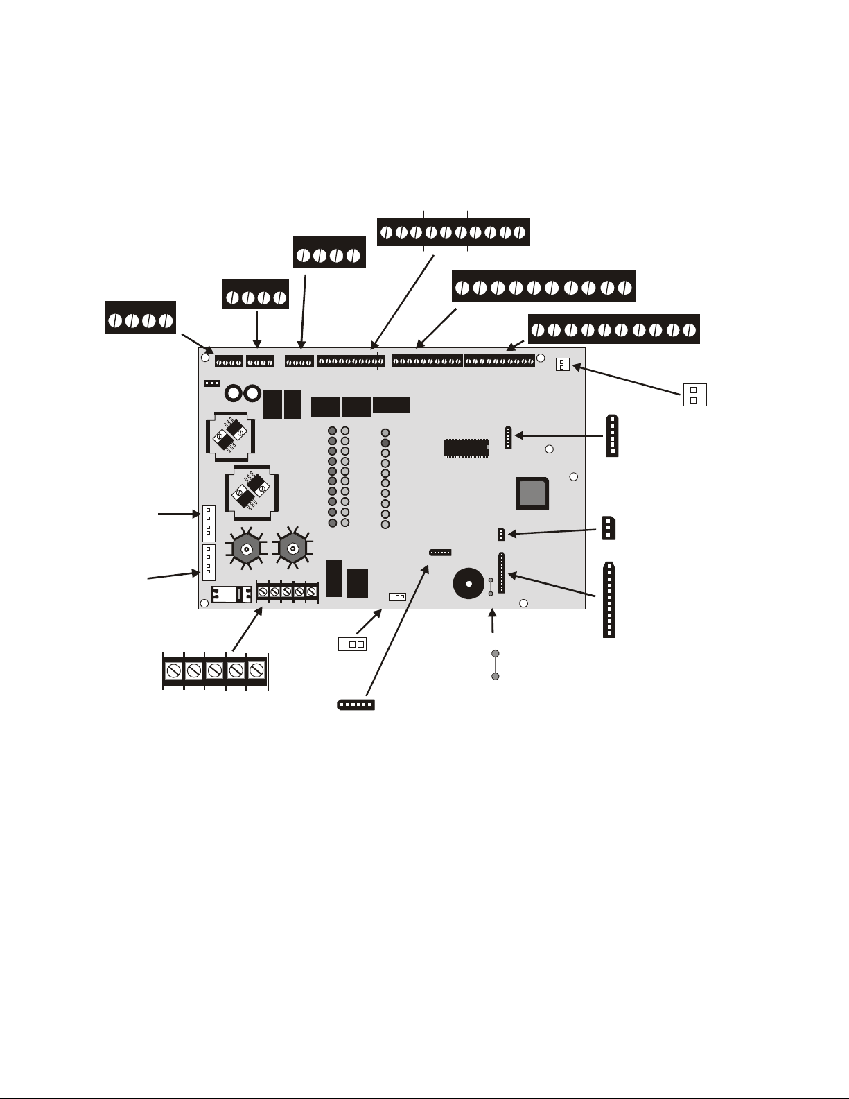
MS-2410B Main Circuit Board
24 V
24 V
NONR ESET
RESET
+ - + -
TB2
J3
PRIMARY
TRANSFO RMER
CONNECTOR
CAUTION!
HIGH VOLTAGE
J2
OPTIONAL
TRANSFO RMER
CONNECTOR
BELL 1
+ - + -
TB3
24 V
RESET
NONRES ET
+ - + -
TB2
J3
J2
NC NO
TROUBLE
RELAY
SUPV
RELAY
NO
C
NC
ZONE 1 ZONE 2 ZONE 3 ZONE 4 ZON E 5
NO
ZO NE 6 ZON E 7 ZO NE 8 ZON E 9 ZO NE 10
BELL 2
REMOTE TRBL UNIT
AC TRBL BUZZ
GND
TB5
ALARM
RELAY
C
TB4
TB6
SUPV
ALARM
24 V
BELL 1
BELL 2
REMOTE TRBL UNIT
AC TRBL BUZZ
GND
+ - + -
TB3
TB5
TB1
CB1
EARTH
HOT
NEUT
TROUBLE
RELAY
RELAY
NC NO
RELAY
CCC
ZONE 1 ZON E 2 Z ONE 3 ZO NE 4 ZO NE 5
NO
NCNCNC
C
NO
+ - + - + - + - + - + - + - + - + - + -
TB4
TB6
ZONE 6 ZONE 7 ZONE 8 ZO NE 9 ZO NE 10
J5
U3
LED-10IM
MODULE
U6
TB7
SECURITY KEY
J4
TB7
J5
LED-10IM
MODULE
J4
SECURITY KEY
J6
J6
MEMBRANE SW CONNECTOR
J1
BAT T - +
TON E/CITY BOX
OPTIONS
J8
J7
JP1
OPTION
SUP ERVIS ION
TO NE/CIT Y BO X
J7
OPTIONS
TB1
H
N
O
E
T
U
T
AC Pow er
J1
JP1
BATT - +
E
A
R
T
H
J8
MEMBRANE SW CO NNECTOR
OPTION
SUPERVISION
MS-2410B Terminals and Connectors
2410layo.cdr
8
Document #51127 Rev.C 11/7/00 P/N 51127:C
Page 9

Product Description
CHAPTER 1 Product Description
The MS-2410B is a 10-zone FACP (Fire Alarm Control Panel), which uses conventional input devices. The panel
accepts waterflow devices, two-wire smoke detectors, four-wire smoke detectors, pull stations and other
normally-open contact devices. Outputs include two Notification Appliance Circuits (NACs), three standard Form-C
relays (alarm, trouble and supervisory) and an EIA-485 port to interface with remote annunciators and optional
remote relay modules. The FACP is field programmable via the panel keypad. It also supervises all wiring, AC
voltage and battery level. The MS-2410BE offers the same features as the MS-2410B but allows connection to 220/
240 VAC input.
1.1 Product Features
• 10 Class B Initiating Device Circuits (IDCs)
✓ All zones accept smoke detectors and any normally open contact device
✓ Zones 1 - 8 configured as general alarm zones
✓ Zones 9 - 10 can be configured as smoke zones or supervisory alarm zones
• Two Class B Notification Appliance Circuits (NACs)
• Form-C Alarm Relay
• Form-C Trouble Relay
• Form-C Supervisory Relay
• 3.6 amps of system power expandable to 6.6 amps
• RTB Remote Trouble Buzzer
• Remote Relay Option Module (ACM-8RF) providing one 5.0 amp relay per zone
• Dress Panel coverplate (DP-2410B)
• Built-in keypad for panel control and programming
• 24 volt operation
• Trouble Reminder
• Alarm Verification (zones 1 through 3 only)
• Interfaces with Fire•Lite annunciators (requires
LED-10IM Option Module)
✓ LED-10 Series Remote Annunciators provide
red alarm and yellow trouble LEDs
✓ LDM-32F Graphic Annunciator Driver
✓ AFM Series LED Annunciators
• Small backbox size 16.9” (42.9 cm) X 14.5” (36.8
cm) X 4.5” (11.43 cm)
• Silence Inhibit Notification Appliance Circuits
• Auto-Silence Notification Appliance Circuits
• Fuseless design
• Low AC voltage sense
• Silent or audible Walktest
FIGURE 1-1:
DP-2410B
DP2410b.cdr
Note: Unless otherwise specified, the term MS-2410B shall be used in this manual to refer to both the MS-2410B and
the MS-2410BE Fire Alarm Control Panels.
Document #51127 Rev. C 11/7/00 P/N 51127:C
9
Page 10
Product Features
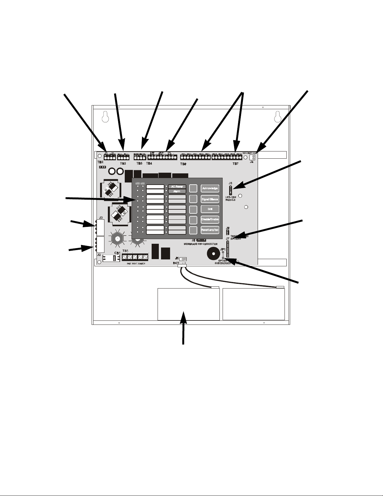
24 VDC
Power
Keypad and
LEDs
Standard
Trans former
Notification
Appliance
Circuits
Remote
Trouble
Buzzer
AT
Zone 1
Zone 2
Zone 3
Zone 4
Zone 5
Zone 6
Zone 7
Zone 8
Zone 9
Zone 10
Trouble
Supervisory
Signal Silence
NAC Fault
Ground Fault
Battery Trouble
Zone Disabled
Annc. Trouble
Relays
10 Input
Zones
Security Key
LED-10IM
Interface
Module
Connector
Reverse
Pol arity
Module
Optional
Trans former
Note: Transformers
are mounted to the
backbox, under the
main circuit board.
Holds up to 12 AH Batteries,
FIGURE 1-2:
MS-2410B Panel
Reverse
Polarity
Module
Supervision
m2410enc.cdr
10
Document #51127 Rev.C 11/7/00 P/N 51127:C
Page 11

Specifications
1.2 Specifications
AC Power - TB1
MS-2410B: 120 VAC, 60 Hz, 2.3 amps
MS-2410BE: 220/240 VAC, 50 Hz, 1.15 amps
Wire size: minimum #14 AWG (2.0 mm
Battery (lead acid only) - J1
Maximum Charging Circuit: Normal Flat Charge—27.6V @ 0.8 amp
Maximum Charger Capacity: 18 Amp Hour battery (MS-2410B cabinet holds maximum 12 Amp Hour battery.
Larger batteries require Fire•Lite BB-17F)
Initiating Device Circuits TB6 and TB7
General Alarm Zones 1 through 8
Smoke Zones or Supervisory Alarm Zones 9 and 10
Operation: All zones Class B
Normal Operating Voltage: Nominal 24 VDC (ripple = 100 mV maximum)
Alarm Current: 15 mA threshold
Short Circuit Current: 42 mA maximum
Maximum Loop Resistance: 100 ohms
End-of-Line Resistor: 4.7K, ½ watt (Part #27072)
Standby Current: 7.26 mA (includes ELR and 2 mA maximum detector current)
Smoke Detector Identifier A
Refer to Fire•Lite Device Compatibility Document for listed compatible devices.
2
) with 600V insulation
Notification Appliance Circuits - TB3
Class B wiring
Operating voltage nominal 24 volts
Current for all external devices: 3.0 amps expandable to 6.0 amps
1
Current Limit: TB3 via PTC
Maximum signaling current/circuit: TB3 = 1.25 amps expandable to 2.5 amps
End-of-Line resistor: 4.7K, ½ watt (Part #71252) for Notification Appliance Circuits
Refer to Fire•Lite Device Compatibility Document for listed compatible devices
Three Form-C Relays - TB4
TB4 relay contact rating: 2.0 amps @ 30 VDC (resistive), 2.0 amps @ 30 VAC (resistive)
Four-wire Smoke Detector Power - TB2 Terminals 3(-) & 4(+)
Maximum ripple voltage: 10 mV
Up to 300 mA is available for powering 4-wire smoke detectors
Recommended maximum Standby current is 50 mA
Operating Voltage nominal 24 volts
RMS
2
1
Refer to Fire•Lite Device Compatibility Document for compatible listed device
1. Total current for nonresettable power, four-wire smoke power, and two Notification Appliance Circuits
amps.
Total system current in excess of 3.6 amps requires the XRM-24 Transformer (XRM-24E for 220/240 VAC applications)
and 12 Amp Hour or 18 Amp Hour batteries.
2. For power supply and battery calculations, refer to “Power Supply Calculations” on page 55.
Document #51127 Rev. C 11/7/00 P/N 51127:C
must not exceed 6.0
11
Page 12
Controls and Indicators
Nonresettable 24 VDC Power - TB2 Terminals 1(-) & 2(+)
Maximum ripple voltage: 10 mV
Total DC current available from this output is up to 500 mA
Operating Voltage nominal 24 volts
RMS
1
Recommended maximum Standby current is 150 mA
Refer to Fire•Lite Device Compatibility Chart for compatible listed devices
Remote Trouble Buzzer - TB5
Operating Voltage: nominal 24 VDC
DC current when RTB Remote Trouble Buzzer is in normal standby (AC Power LED on alone) is 20 mA.
Maximum DC current from this output when RTB Remote Trouble Buzzer is active is 50 mA.
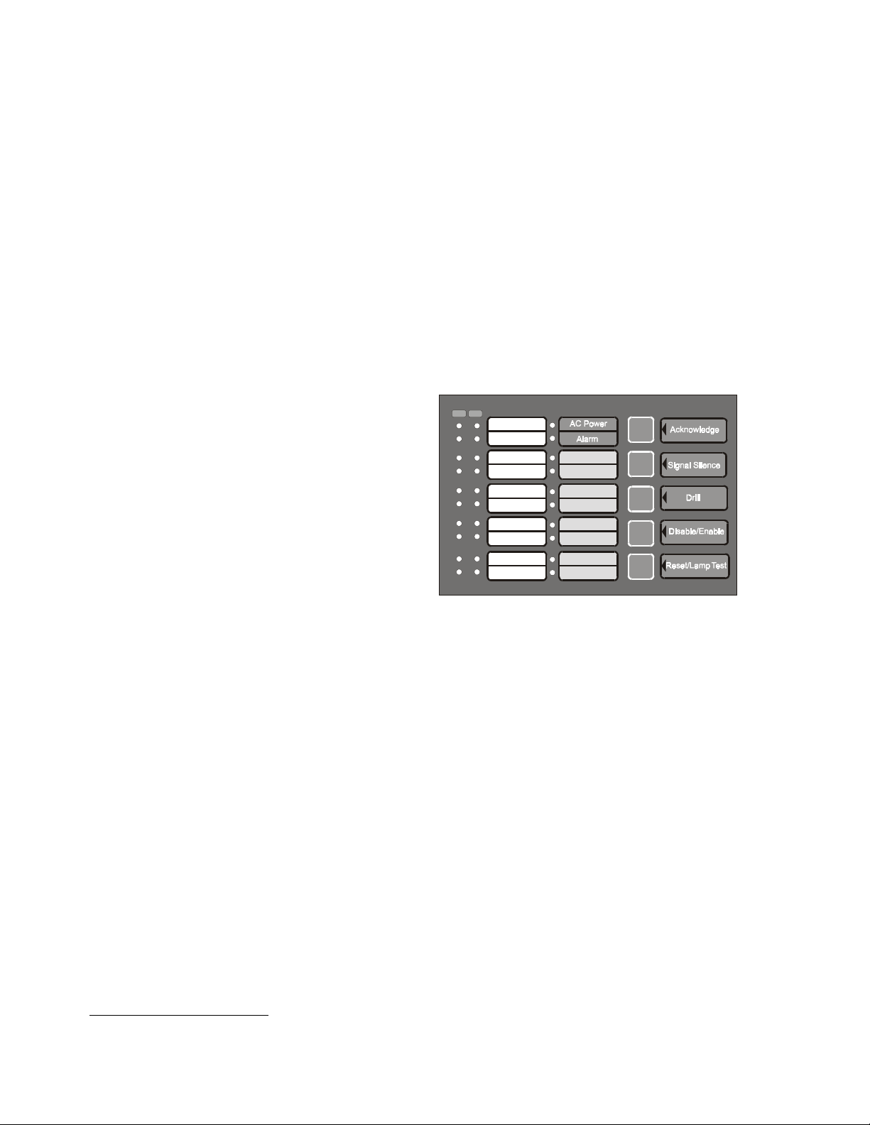
1.3 Controls and Indicators
Front Panel Membrane Keys in Normal Mode
Acknowledge
Signal Silence
Drill
Disable/Enable
Reset/Lamp Test
Note that programming keys function slide-in-labels and
option/feature slide-in labels are also provided and should
be inserted while in Program Mode to view the altered key
functions. Refer to Figure 4-1, “LED Indicators and Keypad,” on page 47 and “Slide-in Labels” on page 61.
LEDs
AC Power - green LED
Alarm - red LED
Trouble - yellow LED
Supervisory - yellow LED
Signal Silence - yellow LED
NAC Fault - yellow LED
Ground Fault - yellow LED
Battery Trouble - yellow LED
Zone Disabled - yellow LED
Annunciator Trouble - yellow LED
Zone Fire Alarm - Zones 1 through 10 - red LEDs
Zone Supervisory Alarm - Zones 9 and 10 only - red LEDs
Zone Trouble - Zones 1 through 10 - yellow LEDs
AT
Zone 1
Zone 2
Zone 3
Zone 4
Zone 5
Zone 6
Zone 7
Zone 8
Zone 9
Zone 10
FIGURE 1-3:
Trouble
Supervisory
Signal Silence
NAC Fault
Ground Fault
Battery Trouble
Zone Disabled
Annunc. Trouble
LEDs and Keypad
2410disp.cdr
2410DISP
Note: A blank slide-in label is provided for circuits 1 through 10 which may be customized by the customer. In
addition, slide-in-labels listing the programming features/options and programming key functions are provided and
should be inserted while in Program Mode.
1. Total current for nonresettable power, four-wire smoke power, and two Notification Appliance Circuits
amps.
Total system current in excess of 3.6 amps requires the XRM-24 Transformer (XRM-24E for 220/240 VAC applica-
tions) and 12 Amp Hour or 18 Amp Hour batteries.
12
Document #51127 Rev.C 11/7/00 P/N 51127:C
must not exceed 6.0
Page 13

Circuits
Local Sounder
A piezo sounder provides separate and distinct sounds for alarm, trouble and supervisory conditions:
• Alarm - on steady
• Alarm Verification - pulse 1 second On and 1 second Off
• Trouble - pulse 1 second On and 1 second Off
• Supervisory - pulse ½ second On and ½ second OFF
1.4 Circuits
Input Circuits
Ten input circuits provide Class B configuration. Input circuits 1 through 10 may be used as standard fire alarm
control panel zones and circuits 9 and 10 may be used as supervisory alarm zones. All ten Initiating Device Circuits accept normally-open contact devices and two-wire smoke detectors.
Output Circuits
• 24 Volt Resettable Power Output 300 mA
• 24 Volt Nonresettable Power Output 500 mA
• 24 Volt Remote Trouble Buzzer Output 50 mA maximum
• 24 Volt Battery Charger (up to 18 AH batteries)
• EIA-485 Port (interfaces to LED-10 Series Annunciators, AFM Series and LDM Graphic Series Annunciators
and ACM-8RF Remote Relay Module)
Notification Appliance Circuits
Two Notification Appliance Circuits Class B.
Relays
Three dry Form-C relays for system alarm, system trouble and supervisory are provided standard. Contacts are
rated 2.0 amps @ 30 VDC (resistive) and 2.0 amps @ 30 VAC (resistive).
EIA-485 Port (Requires LED-10IM Module)
EIA-485 compatible port on the LED-10IM option module supports up to 10 different device addresses which can
consist of LED-10 Series Remote Annunciators, ACM-8RF Relay Modules, AFM Series Annunciators or LDM
Graphic Series Annunciators or any combination of the four modules.
Battery Charger
Battery Charger will charge up to 18 AH batteries. The MS-2410B cabinet holds a maximum of 12 AH batteries.
The Fire•Lite BB-17F is required to hold 18 AH batteries. The charger is rated for 800 mA maximum current.
1.5 Components
Main Circuit Board
The main circuit board contains the system's
CPU, power supply, other primary components and wiring interface connectors.
Optional modules plug in and are mounted to
the main circuit board. The main circuit board
is delivered premounted in the cabinet.
24 V
24 V
BELL 1 BELL 2
RESET
NONRESET
REMOTE TRBL BUZZER
GRD
+ - + -
+ - + -
TB2
TB3
J3
TB1
CB1
J2
HOT
AC TRBL BUZZ
TB5
EARTHNEUT
SUPV
TROUBLE
ALARM
RELAY
ZONE 1 ZONE 2 ZONE 3 ZONE 4 ZONE 5 ZONE 6 ZONE 7 ZONE 8 ZONE 9 ZONE 10
RELAY
RELAY
NC
CCCNONONC NO
NC
+ - + - + - + - + - + - + - + - + - + -
TB6
TB4
MEMBRANE SW CONNECTOR
J1
BATT - +
SECURITY KEY
J4
TB7
J5
U3
LED-10IM
MODULE
U6
J6
TONE/C ITY BOX
OPTIONS
JP1
OPTION
SUPERVISION
J7
2410brd.cdr
J8
FIGURE 1-4:
Document #51127 Rev. C 11/7/00 P/N 51127:C
Main Circuit Board
13
Page 14
Optional Modules
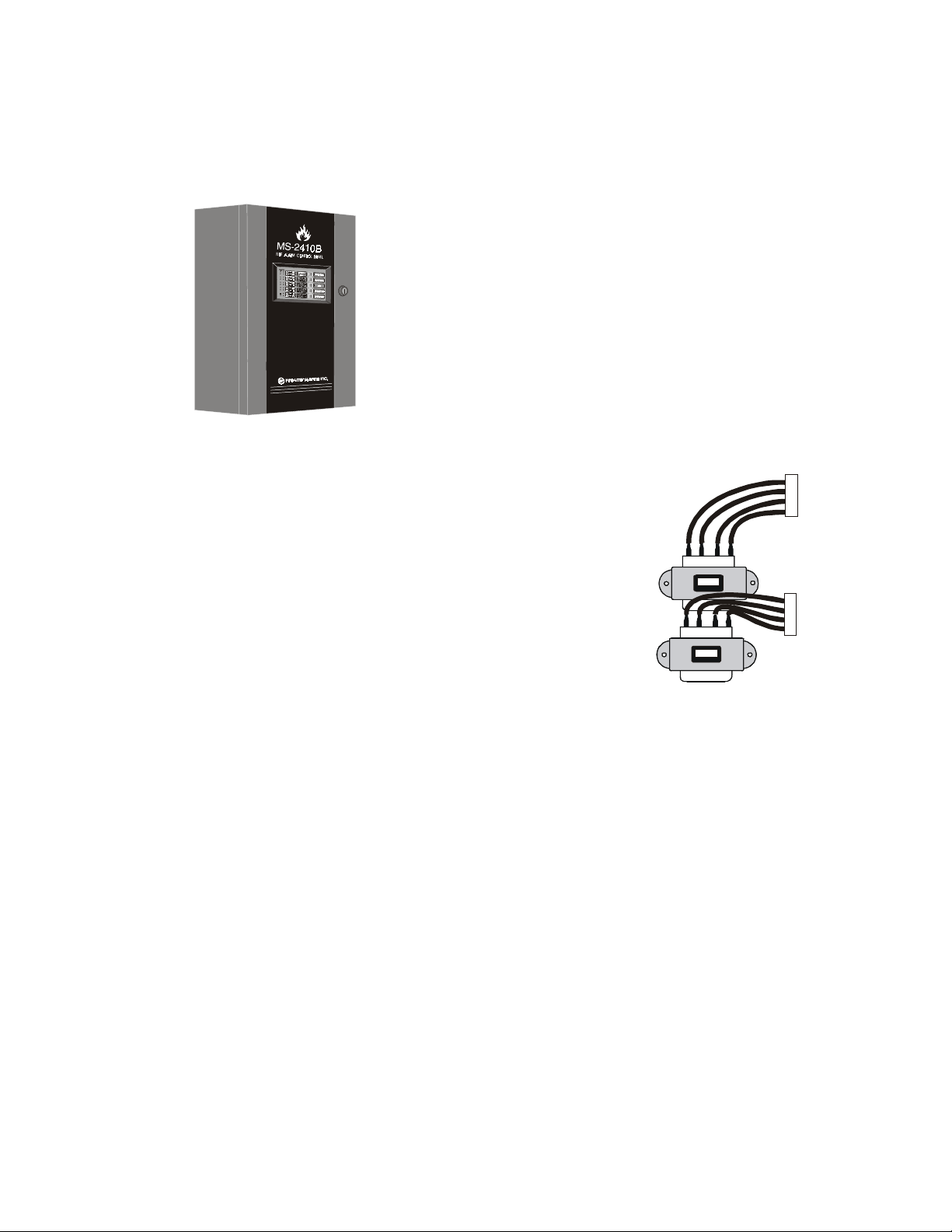
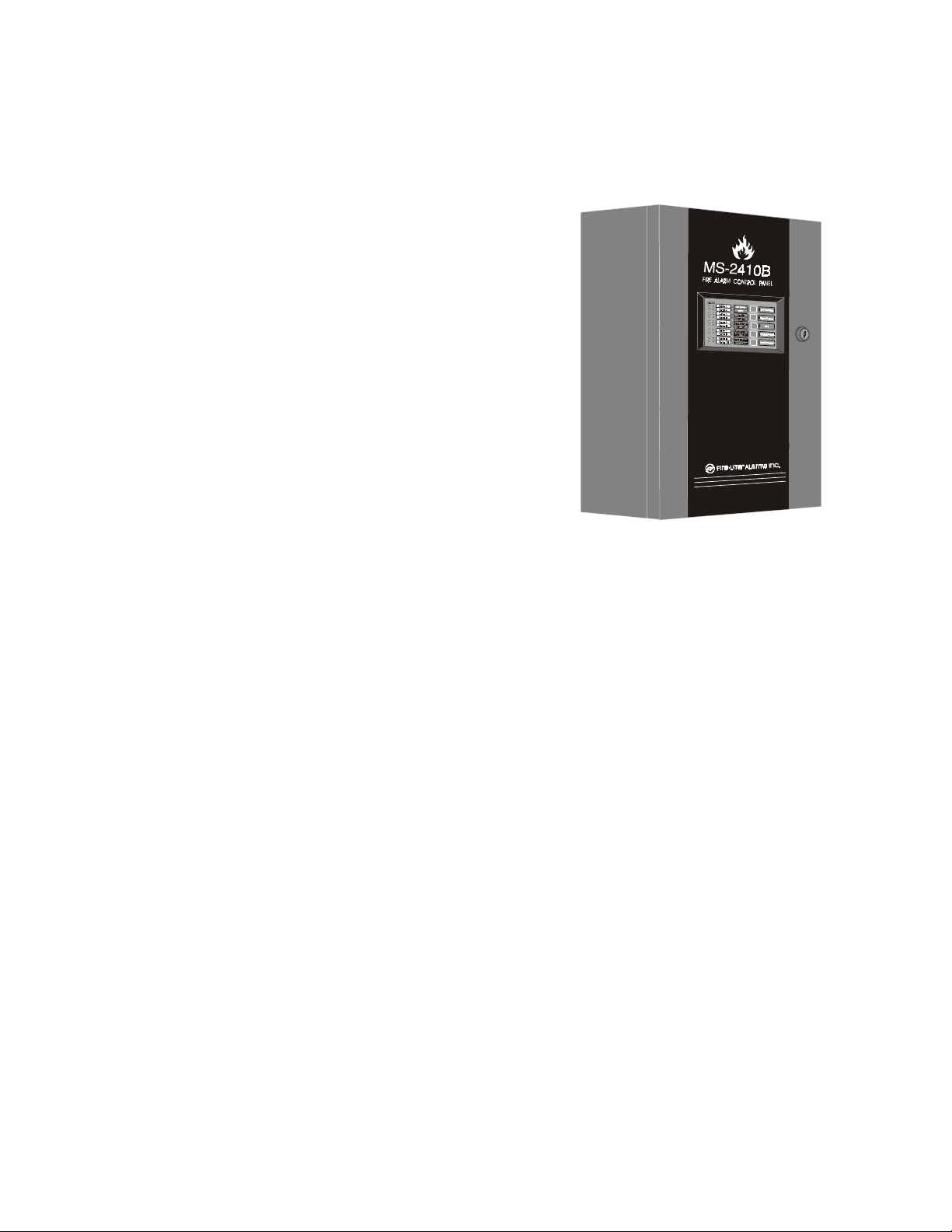
Cabinet
The cabinet is red and the backbox measures 16.90” (42.9 cm) long X 14.50” (36.8 cm) high X 4.5” (11.43 cm)
deep and provides space for two batteries (up to 12 Amp Hours). Also available is an optional dress panel,
DP-2410B, which mounts inside the cabinet.
ms2410bcdr
FIGURE 1-5:
MS-2410B Cabinet
Transformer Assembly
One 100VA transformer is provided standard with the panel.
An optional 100VA transformer XRM-24 (XRM-24E for
220/240 VAC applications) is available to provide maximum
accessory power.
Batteries
Standard XRM-24(E)
The cabinet provides space for 12 Amp Hour batteries (larger
batteries up to 18 Amp Hour batteries, use the listed Fire•Lite
BB-17F battery box). Batteries must be ordered separately.
Optional XRM-24(E)
FIGURE 1-6:
Transformer Assemblies
1.6 Optional Modules
LED-10IM
The LED-10IM Interface Module provides an EIA-485 port to support the LED-10 Series Remote Annunciator,
LDM Series Annunciator, AFM Series Annunciator and ACM-8RF Relay Modules. EIA-485 wiring is
supervised for short, open and grounded circuits by this module. The LED-10IM mounts to connector J5 on the
main circuit board.
4XTMF Transmitter Module
The 4XTMF provides a supervised output for local energy municipal box transmitter and alarm and trouble
reverse polarity. It includes a disable switch and disable trouble LED. A module jumper option allows the reverse
polarity circuit to open with a system trouble condition if no alarm condition exists.
1.7 Optional Accessories
Dress Panel
A dress panel (DP-2410B) is available as an option. The dress panel restricts access to the system wiring while
allowing access to the membrane switch panel. Refer to Figure 1-1, “DP-2410B,” on page 9.
14
Document #51127 Rev.C 11/7/00 P/N 51127:C
Page 15
Optional Accessories
Battery Box
The Fire•Lite BB-17F battery box may be used to house
two batteries greater than 12 Amp Hour to a maximum of
18 Amp Hour. The battery box mounts directly below the
MS-2410B cabinet, centered to the main circuit board. The
BB-17F is red and is provided with knockouts.
bb17.cdr
Remote Trouble Buzzer
One Remote Trouble Buzzer can be connected to the
MS-2410B control panel using four wires. The remote unit
includes an AC LED, System Trouble LED and piezo
sounder which are controlled by the MS-2410B. It mounts
to a single-gang electrical box.
ACM-8RF Relay Module
The ACM-8RF option module provides eight Form-C relays
rated at 5.0 amps each. The Relay Module connects to the
EIA-485 port off of the LED-10IM option module. Relays
are assigned to each of the 10 Initiating Device Circuits.
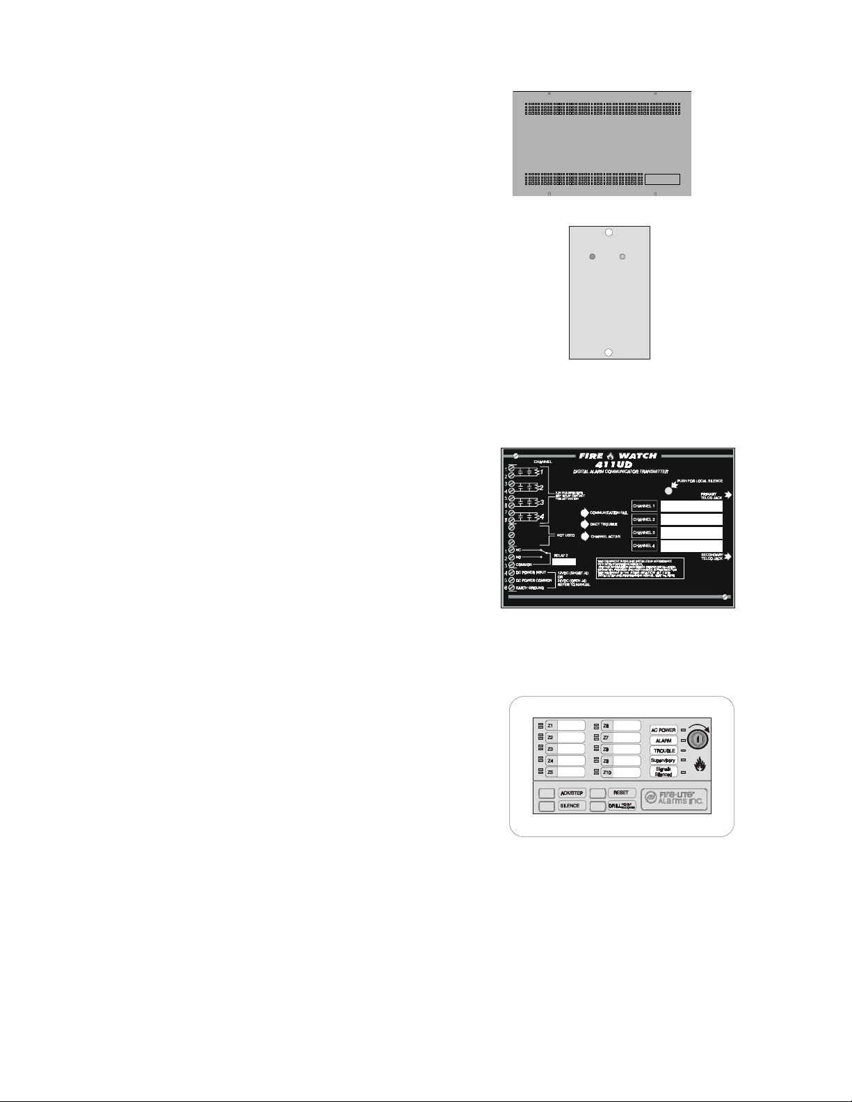
411 and 411UD Digital Alarm Communicator/Transmitter
The three input/channel 411 and the four input/channel 411UD
are dual line, digital alarm communicator transmitters which
can be used as slave communicators with the MS-2410B. The
inputs/channels are compatible with normally open relay contacts, require End-Of-Line (EOL) resistors, are supervised and
are fully programmable. The communicators interface with
the public switched telephone network and are compatible
with most central station receivers. Power supplied must be 12
or 24 volts, filtered and nonresettable. The communicators are
mounted in a small metal enclosure, providing a variety of
mounting options. Refer to the 411 or 411UD manual for
detailed information on installation, wiring and programming.
FIGURE 1-7:
FIGURE 1-8:
FIGURE 1-9:
BB-17F Battery Box
rtbbuzz.cdr
RTB Remote Trouble Buzzer
411udcvr.cdr
411UD Communicator
LED-10 Series Annunciator (LED Zone Type Annunciator)
The LED-10 Series is a 10 zone LED annunciator which
mounts on a 3-gang electrical box and provides LED
indication of the following:
• Alarm Zones 1 through 10
• Supervisory Zones 9 and 10 (LED-10LS2 only)
• Trouble Zones 1 through 10
FIRE ANNUNCIATOR
• AC Power (green)
• System Alarm (red)
• System Trouble (yellow)
FIGURE 1-10:
LED-10 Series Annunciator
• System Supervisory (yellow)
• Alarm Silence (yellow)
A local trouble sounder is standard and switches for remote Acknowledge, Silence, Drill and Reset are also provided on the LED-10 only. Wiring is inherently supervised by the FACP. Slide-in paper labels permit an easy
change of zone information. DIP switches allow the enabling and disabling of the local piezo sounder (with
approval of local AHJ), enabling and disabling of the mechanical keyswitch which may be used to prevent unauthorized use of the function switches and selection of annunciator receive/transmit mode.
Note that the LED-10 Series Remote Annunciators require the use of the LED-10IM Interface Module.
Document #51127 Rev. C 11/7/00 P/N 51127:C
led10.cdr
15
Page 16
Optional Accessories
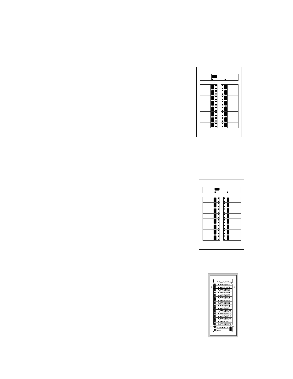
AFM Series Annunciators (LED Zone Type)
The AFM Series Annunciators remotely display system status. The AFM/AEM-16AT annunciators display zone
alarm and trouble status. In addition, they provide remote Acknowledge, Silence, Reset and Drill functions. The
AFM Series Annunciators require the use of the LED-10IM Interface Module. For more detailed information,
refer to the appropriate AFM Annunciator manual.
✓ AFM-16ATX - The Annunciator Fixed Module-16ATX contains
16 red alarm and 16 yellow trouble LEDs, a system trouble LED,
an ON LINE/POWER LED and a local piezo sounder with
switches for Acknowledge, Silence, Reset and Drill. The
AFM-16ATX is fixed at address '1' and will accept up to 3
AEM-16ATF Expanders. The AFM-16ATX can be mounted in a
Fire•Lite ABS-1F or ABF-1F backbox. Refer to the AFM-16ATX
Manual for detailed information.
Note that only one AFM-16ATX
is required to annunciate 10 zones of alarm and trouble, provided '8
Point Shift' function is selected. Refer to Annunciator Manual P/N
15390 for additional information.
✓ AFM-16ATXCS4 - This module is the same as the AFM-16ATX
except with four yellow supervisory LEDs in place of the four red
FIGURE 1-11:
AFM-16ATX
LEDs at points 13 through 16.
✓ AFM-16ATXCS8 - This module is the same as the AFM-16ATX except with eight yellow supervisory
LEDs in place of the eight red LEDs at points 9 through 16.
✓ AFM-16ATXCS16 - This module is the same as the AFM-16ATX except with sixteen yellow
supervisory LEDs in place of the sixteen red LEDs at points 1 through 16.
✓ AEM-16ATF - The Annunciator Expander Module-16ATF con-
nects to the AFM-16ATX and adds 16 sets of red alarm LEDs
and yellow trouble LEDs. Up to three AEM-16ATFs may be
added to an AFM-16ATX but only one is required.
Note that one
AEM-16ATF is required with an AFM-16ATX to annunciate 10
zones of alarm and trouble as well as general system status provided '8 Point Shift' function is not selected. Refer to Annunciator Manual P/N 15390 for additional information.
✓ AFM-16ATF - The Annunciator Fixed Module-16ATF contains
16 red alarm and 16 yellow trouble LEDs, a system trouble LED,
an ON LINE/POWER LED and a local piezo sounder with
switches for Acknowledge, Silence, Reset and Drill. The
AFM-16ATF is fixed at address '1' and communication is via the
EIA-485 data line. The AFM-16ATF can be mounted in a
Fire•Lite ABS-1F or ABF-1F backbox. Refer to the AFM-16AT
FIGURE 1-12:
AFM-16ATF
Manual for detailed information.
✓ AFM-16AF - The Annunciator Fixed Module-16AF has 16 red
alarm LEDs. Multiple annunciators may be used by setting all
annunciators to Receive Only, except the last AFM-16AF in
line. Each annunciator's address is internally fixed at '1' and
communication is via the EIA-485 data line. The Local
Silence/Acknowledge switch functions as local lamp test and
silence for annunciator piezo. LEDs include On-Line and System Trouble indicators. The AFM-16AF Annunciator can be
mounted in a standard 4-gang electrical box. Refer to the
AFM-16AF Manual for detailed information.
afm16atx.cdr
afm16atx.cdr
16
Document #51127 Rev.C 11/7/00 P/N 51127:C
FIGURE 1-13:
afm-16a.cdr
AFM-16AF
Page 17
Optional Accessories
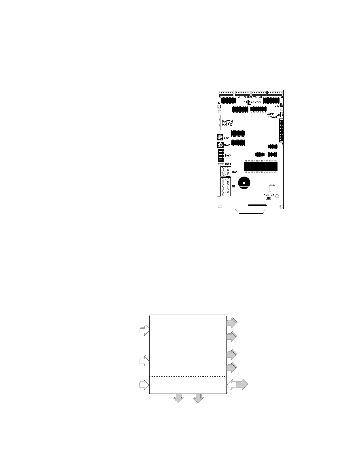
LDM Series Lamp Driver Modules (Graphic Annunciator)
The LDM Series Lamp Driver Modules, which consist of the LDM-32F master and LDM-E32F expander modules, are used to provide an interface to a custom graphic LED annunciator. The master module provides power
and control for a maximum of three expander modules (expander modules are not required when interfacing to the
MS-2410B). The LDM-32F and LDM-E32F have output connectors which are used to drive lamps or LEDs and
input connectors which are used for remote switch functions. The LDM Series requires the use of the LED-10IM
Interface Module. Refer to the LDM Series Lamp Driver Modules Manual for a complete description.
✓ LDM-32F - The Lamp Driver Module has 32
alarm lamp/LED driver outputs which sink current to system common (-) on activation. A single
positive (+) voltage is required to supply total
operating power for all lamps or LEDs when all
drivers are activated. The LDM-32F provides a
separate driver for system trouble and inputs for a
local lamp test switch. A maximum of 16 external control switches may be wired to the
LDM-32F. DIP switch SW3 is used to enable or
disable the onboard piezo sounder, enable remote
switch functions, select a flashing LED function
for new alarms and troubles and other functions.
Switch SW4 is used to configure the module to
annunciate 32 alarms or 16 alarms and 16 troubles. A green ON-LINE LED flashes to indicate
ongoing communications with the host FACP.
One LDM-32F supports up to three LDM-E32F
modules. The LDM-32F is supplied with four
standoffs and screws for mounting to a CHS-4L
FIGURE 1-14:
LDM-32F Module
ldm-32f.cdr
chassis or custom backbox.
FCPS-24F(E) Remote Power Supply (System Power Expansion)
The FCPS-24F(E) is a compact, remote power supply and battery charger. This remote power supply consists of a
filtered 24 VDC output that may be configured to drive up to four Notification Appliance Circuits (four Class B or
two Class A and two Class B). Alternately, the four Notification Appliance Circuits may be used as auxiliary
power configured for resettable or nonresettable operation.
The FCPS-24F(E) may be used in a number of different applications. It may be used as a remotely mounted power
supply and battery charger powering up to four, coded or noncoded, Notification Appliance Circuits. Alternately,
any or all of these circuits may be used as 24 VDC output circuits capable of powering four-wire smoke detectors
or any device that requires filtered power. These circuits may be configured as resettable or nonresettable outputs
to expand FACP auxiliary system power.
Class B/Class A Notification Appli-
Notification Appliance Circuit
Control Input #1 (from FACP)
Notification Appliance Circuit
Control Input #2 (from FACP)
FIGURE 1-15:
AC Power
FCPS-24F(E)
Specific Application
Power
FCPS Trouble
Contact Output
ance Circuit or 24 VDC Output #1
Class B Notification Appliance
Circuit or 24 VDC Output #2
Class B/Class A Notification Appli-
ance Circuit or 24 VDC Output #3
Class B Notification Appliance
Circuit or 24 VDC Output #4
Battery Charger
fcpsblok.cdr
Document #51127 Rev. C 11/7/00 P/N 51127:C
17
Page 18

Optional Accessories
One of the most common applications for the FCPS-24F(E) remote power supply utilizes the NAC expander
mode. In this application, one or two Notification Appliance Circuits (NACs) are connected from the main FACP
NAC output(s) to the remote power supply Control Input circuits. When these Control Input circuits activate (due
to reverse polarity of the NAC output), the power supply will activate its corresponding outputs. NAC Control
Input #1 controls power supply output circuits #1 and #2. NAC Control Input #2 controls output circuits #3 and
#4.
During the inactive state, the remote power supply supervises its NAC field wiring for short and open circuits. If
a fault is detected, the supply will enter a trouble condition and illuminate the corresponding NAC trouble LED
(Output Circuits 1-4), however, once the Notification Appliance Circuits are activated, the supervision is disabled
and the circuits are no longer supervised. Supervision of other power supply faults such as low battery, Earth
Fault, AC loss and battery charger failure will continue and may be monitored via the independent trouble relay
contact.
If a specific application requires that all four outputs activate at the same time, only one NAC control input from
the FACP is necessary. For this application, The Notification Appliance Circuit from the FACP is wired into NAC
Control Input #1 of the remote supply and then a pair of wires are connected from NAC Control Output #1 to
NAC Control Input #2. Refer to the FCPS-24F(E) Installation, Operation and Application Manual for a complete
description and examples of applications.
18
Document #51127 Rev.C 11/7/00 P/N 51127:C
Page 19
Installation
CHAPTER 2 Installation
2.1 Mounting Options
The cabinet may be either semi-flush or surface mounted. The door
is removable during the installation period by opening and lifting off
the hinges. The cabinet mounts using two key slots and two additional 0.250" (6.35 mm) diameter holes located in the backbox. The
key slots are located at the top of the backbox and the two securing
holes at the bottom.
Carefully unpack the system and check for shipping damage. Mount
the cabinet in a clean, dry, vibration-free area where extreme temperatures are not encountered. The area should be readily accessible
with sufficient room to easily install and maintain the panel. Locate
the top of the cabinet approximately five feet above the floor with the
hinge mounting on the left. Determine the number of conductors
required for the devices to be installed. Sufficient knockouts are provided for wiring convenience. Select the appropriate knockout(s)
and pull the required conductors into the box. All wiring should be
in accordance with the National and/or Local codes for fire alarm
systems.
FIGURE 2-1:
ms2410b.cdr
MS-2410B Mounting
2.2 Backbox Mounting
✓ Open the door and lift the door off the pin hinges.
✓ Remove the main PC board assembly and transformer(s) which are packaged with the backbox. Set the
board and transformer aside in a safe, clean place. Avoid static discharge which may damage the board.
✓ Mark and predrill holes for the top two keyhole mounting bolts using the dimensions illustrated.
✓ Install two upper fasteners in the wall with the screw heads protruding.
✓ Using the upper 'keyholes', mount the backbox over the two screws.
✓ Mark and drill the lower two holes.
✓ Mount backbox, install remaining fasteners and tighten.
✓ When the location is dry and free of construction dust, install the transformer and main circuit board as
described in the following sections.
Document #51127 Rev. C 11/7/00 P/N 51127:C
19
Page 20
Backbox Mounting
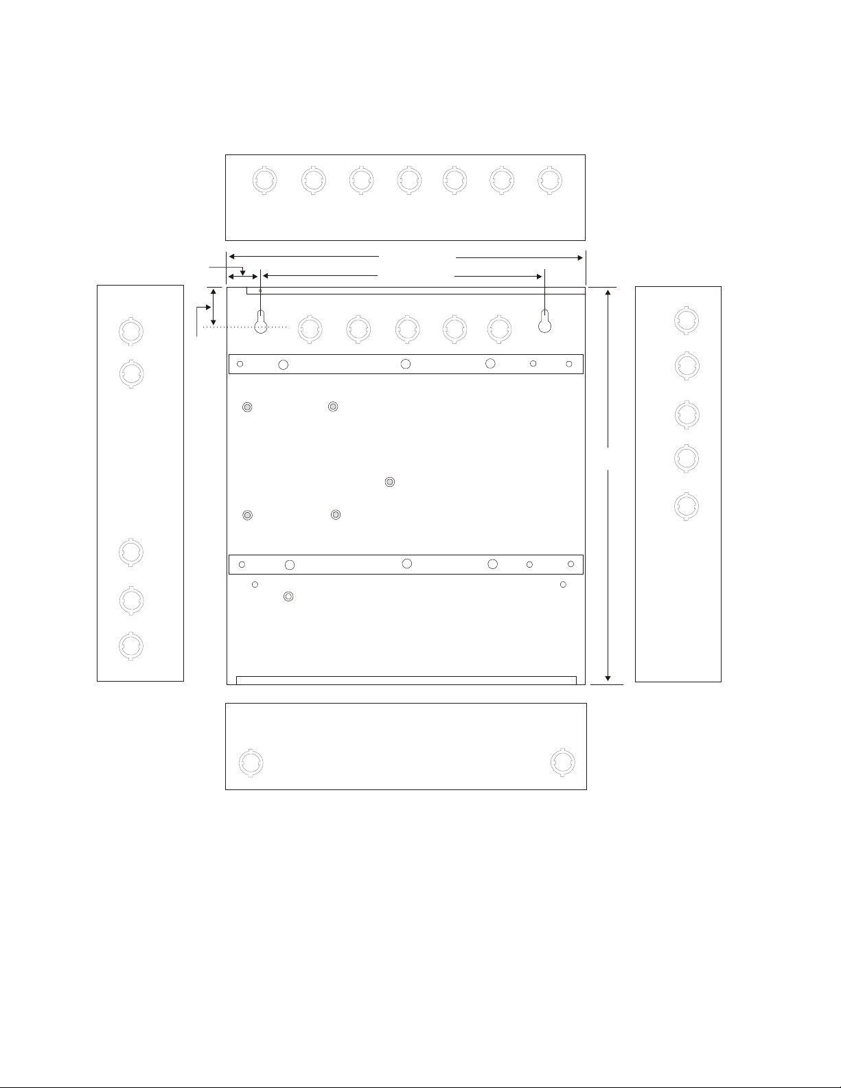
Draw wires through the respective knockout locations.
To p
Left Side
1.5”
(3.81 cm)
1.55”
(3.94 cm)
14.5” (36.83 cm)
11.5” (29.21 cm)
Right Side
16.9””
(42.93 cm)
20
Bottom
FIGURE 2-2:
Document #51127 Rev.C 11/7/00 P/N 51127:C
Cabinet Dimensions and Knockout Locations
5210bkbx.cdr
Page 21
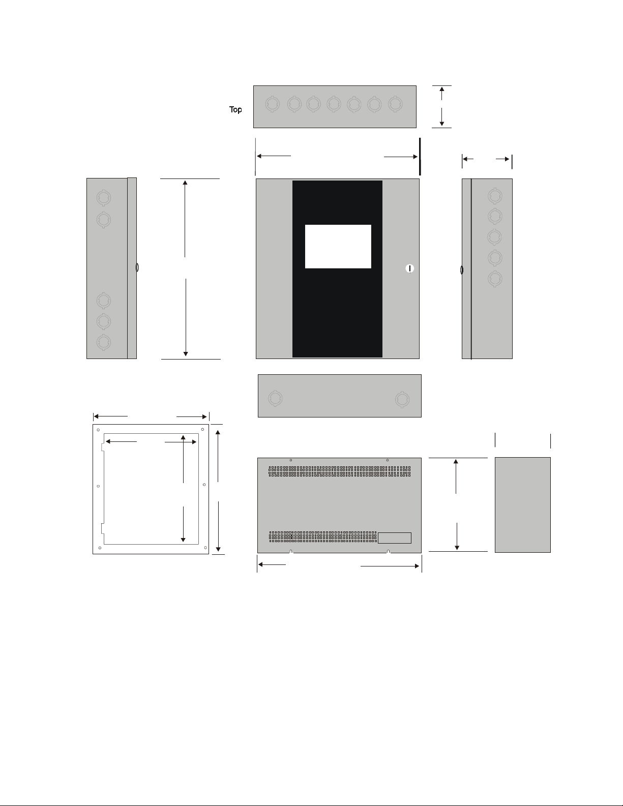
Backbox Mounting
Depth = 4.5" (11.43 cm)
Left Side
Door = 17.114" (43.37 cm)
Backbox = 16.9" (42.9 cm)
17.620"
(44.75 cm)
14.620"
(37.14 cm)
Bottom
Door = 14.714" (37.37 cm)
Backbox = 14.5" (36.8 cm)
Depth =
4.695"
11.93 cm)
2410bcab.cdr
Right Side
Depth = 4.75"
(12.07 cm)
17.020"
(43.23 cm)
TR-4-R Trim Ring
20.020"
50.85 cm)
Battery Box=8.5"
(21.59 cm)
(Optional BB-17F)
Battery Box=14.5" (36.8 cm)
(Optional BB-17F)
When batteries larger than 12 Amp Hour are being used, the BB-17F battery box (or equivalent) must be
installed. To install the BB-17F:
Mount the FACP cabinet to the wall.
1.
Remove knockouts on the bottom of the FACP cabinet and top of the BB-17F.
2.
Using conduit, hang the BB-17F from the FACP cabinet making sure there is at least ½" of
3.
clearance between the two cabinets.
Anchor the BB-17F to the wall.
4.
FIGURE 2-3:
FACP Backbox
Document #51127 Rev. C 11/7/00 P/N 51127:C
21
Page 22

Transformer Installation
2.3 Transformer Installation
One 100 VA transformer P/N: XRM-24 (XRM-24E for 220/240 VAC applications) is supplied standard with the
FACP. An optional second XRM-24(E) transformer can be ordered and installed to supply additional system power.
To install the transformer(s):
✓ Position the supplied transformer over the top set of mounting studs as illustrated below
✓ Secure to the studs with the supplied nuts
✓ If a second optional transformer has been ordered, position it over the bottom set of mounting studs as
illustrated below
✓ Secure the optional transformer with the supplied nuts
✓ Before installing the main circuit board, be sure to plug the transformer connector into J3 Primary
Transformer Connector on the main circuit board, and the optional transformer connector into J2
Optional Transformer Connector on the main circuit board.
Primary (standard) XRM-24(E) Transformer
Primary (Standard)
Transformer Mounting Studs
Optional XRM-24(E) Transformer
Optional
FIGURE 2-4:
Transformer Installation
MS-2410B Backbox
22
Document #51127 Rev.C 11/7/00 P/N 51127:C
Page 23

Main Circuit Board Installation
2.4 Main Circuit Board Installation
The circuit board contains static-sensitive components. Always ground yourself with a proper wrist strap before han-
!
dling any boards so that static charges are removed from the body. Use static suppressive packaging to protect electronic assemblies.
Install the supplied standoffs in the backbox as follows (refer to Figure 2-5 for locations):
1.
• Install large plastic standoff in center of box by screwing threaded female end onto the pem stud
• Install four metal standoffs on mounting rails by screwing male threaded ends into threaded holes on rails
• Install six short plastic standoffs by pressing into holes on mounting rails
Position the main circuit board near the installed transformer(s) and plug the transformer connector(s) into J3
2.
(Primary) and J2 (Optional) located on the main circuit board
Position the main circuit board over the installed standoffs on the backbox rails as illustrated below
3.
Secure the main circuit board to the standoffs with the supplied screws
4.
Metal Standoff
metal standoff
metal standoff
Primary Transformer
Optional Transformer
small plastic standoffs
small plastic standoffs
MS-2410B Backbox
24 V
24 V
BELL 1 BELL 2
RESET
NONRESET
+ - + -
+ - + -
TB2
TB3 TB5
J3
TB1
CB1
J2
HOT
REMOTE TRBL BUZZER
GRD AC T RBL BUZZ
EARTHNEUT
metal standoff
large plastic standoff
metal standoff
SUPV
TROUBLE
ALARM
RELAY
ZONE 1 ZON E 2 ZONE 3 ZO NE 4 ZONE 5 ZONE 6 ZON E 7 ZON E 8 ZO NE 9 ZONE 10
RELAY
RELAY
NC
CCCNONONC NO
NC
+ - + - + - + - + - + - + - + - + - + -
TB6
TB4
MEMBRANE SW CONNECTOR
J1
BATT - +
SECURITY KEY
J4
TB7
J5
U3
LED-10IM
MODULE
U6
J6
TONE/CITY BOX
OPTIONS
JP1
OPTION
SUPERVISION
J7
J8
MS-2410B Main Circuit Board
Metal Standoff
Grounding Stud
FIGURE 2-5:
Metal Standoff
MS-2410B Backbox
Main Circuit Board Installation
Document #51127 Rev. C 11/7/00 P/N 51127:C
23
Page 24

Operating Power
2.5 Operating Power
WARNIN G:
!
before servicing. The panel and associated equipment may be damaged by removing and/or inserting cards, modules
Several different sources of power can be connected to this panel. Disconnect all sources of power
or interconnecting cables while this unit is energized.
Primary Power Source (AC) and Earth Ground Connections
AC power connections are made inside the control panel cabinet. The primary power source for the MS-2410B is
120 VAC, 60 Hz, 2.3 amps and the MS-2410BE is 220/240 VAC, 50 HZ, 1.15 amps. Run a pair of wires (with ground
conductor) from the protected premises main breaker box to TB1 of the main circuit board. As per the National Electrical Code, use 14 AWG (2.00 mm
2
, 1.6 mm O.D.) or heavier gauge wire with 600V insulation. No other equipment
may be connected to this circuit. In addition, this circuit must be provided with overcurrent protection and may not
contain any power disconnect devices. A separate Earth Ground connection must be made to ensure proper panel
operation and lightning and transient protection. Connect the Earth Ground wire [minimum 14 AWG (2.00 mm
the mounting stud located on the cabinet near TB1.
Do not use conduit for the Earth Ground connection since this
does not provide reliable protection.
Secondary Power Source (Batteries)
Observe polarity when connecting the battery. Connect the battery cable to J1 on the main circuit board using the
plug-in connector and cable provided. The battery charger is current-limited and capable of recharging sealed lead
acid type batteries. The charger shuts off when the system is in alarm. See “Wire Requirements” on page 60 for calculation of the correct battery rating.
WARNIN G:
!
If contact is made with sulfuric acid, immediately flush the skin or eyes with water for 15 minutes and seek immediate
Battery contains sulfuric acid which can cause severe burns to the skin and eyes and can destroy fabrics.
medical attention.
2
)] to
24
VAC In p ut
AT
Zone 1
Zone 2
Zone 3
Zone 4
Zone 5
Zone 6
Zone 7
Zone 8
Zone 9
Zone 10
Earth
Hot
Ground
Neutral
FIGURE 2-6:
Document #51127 Rev.C 11/7/00 P/N 51127:C
Trouble
Supervisory
Signal Silence
NAC Fault
Ground Fault
Battery Trouble
Zo ne Dis abled
Annc. Trouble
24 VDC Batteries
Operating Power Connections
J1
+ - + -
TB1
2410pwrl.cdr
Page 25

Input Circuits
2.6 Input Circuits
The control panel has 10 zone input circuits. The maximum loop resistance limit for each input circuit is 100 ohms.
All field wiring of each zone is supervised for opens and ground faults. Both conditions are visually and audibly
annunciated.
Each zone is a Class B Initiating Device Circuit (IDC) designed to accept any normally-open contact devices and conventional 2-wire, 24 volt smoke detectors.
All zones may be configured for general fire alarm applications. In addition, zones 9 and 10 can be configured as fire
alarm zones or supervisory alarm zones.
Four-wire smoke detectors may be connected to any zone. Resettable power is provided via TB2 Terminals 3 and 4.
Refer to the Fire•Lite Device Compatibility Document for a list of compatible smoke detectors.
It is allowable to mix an assortment of device types (i.e. smoke detectors, heat detectors, pull stations, etc.) on any
zone. If, however, alarm verification is employed on zones 1, 2 and 3, only smoke detectors should be installed on
these three zones.
Class B Initiating Device Circuit (supervised and power-limited). 4.7K,
UL listed compatible 2-wire smoke detector
Heat Detector
P/N: 71252
½watt,
UL listed compatible 2-wire smoke detector
Manual Pull StationManual Pull Station
Heat Detector
Dummy Load all unused circuits (P/N: 71245)
TB6
B+ B- B+ B- B+ B - B + B - B + B - B + B- B+ B- B+ B- B+ B- B+ B-
ZONE 1 ZONE 2 ZONE 3 ZONE 4 ZONE 5 ZONE 6 ZONE 7 ZONE 8 ZONE 9 ZONE 10
FIGURE 2-7:
Class B Initiating Device Circuit Connections
Document #51127 Rev. C 11/7/00 P/N 51127:C
TB7
2410tb6.cdr
25
Page 26

Output Circuits
2.7 Output Circuits
DC Power Output Connections
.
4-Wire Smoke Detector Power (300 mA) 24
VDC filtered, resettable power for 4-wire
smoke detectors can be obtained from TB2
Nonresettable Power (500 mA) 24 VDC
filtered, nonresettable power can be
obtained from TB2 Terminals 1(-) and 2(+).
Terminals 3(-) and 4(+)
TB2
4 3 2 1
FIGURE 2-8:
Auxiliary Power Connections
Notification Appliance Circuits
The MS-2410B provides two Notification Appliance Circuits standard as Class B. Each circuit is capable of a
maximum of 2.5 amps of current. Total current drawn from these as well as other DC power outputs cannot
exceed 3.6 amps with the standard transformer, 6.6 amps if an optional XRM-24(E) Transformer is installed.
Circuits are supervised. Refer to the Fire•Lite Device Compatibility Document for a listing of compatible notification appliances.
Class B Notification Appliance Circuit (supervised). 4.7K ohm,
P/N: 71252
2410tb2.cdr
½ watt.
Polarized Horn
Polarized Horn
Note: Notification Appliance Circuit polarity
shown in alarm
state.
FIGURE 2-9:
+
+
+
Polarized BellPolarized Bell
Polarized Horn
Polarized Horn
+
+
+
TB3
2410bell.cdr
Notification Appliance Circuit Connections
Dummy Load all unused circuits (P/N: 71245)
26
Document #51127 Rev.C 11/7/00 P/N 51127:C
Page 27

Power-limited Wiring Requirements
Standard Relays
The control panel provides three Form-C relays rated for 2.0 amps @ 30 VDC (resistive) and 2.0 amps @ 30 VAC
(resistive).
Relay connections may be power-limited or nonpower-limited, provided that a minimum of
0.25" is maintained between conductors of power-limited and nonpower-limited circuits.
ALARM
RELAY
TROUBLE
RELAY
1 2 3 4 5 6 7 8 9
Relay contacts shown with no power applied to panel
SUPV
RELAY
TB4
FIGURE 2-10:
ALARM
RELAY
TROUBLE
RELAY
C NC NO C NC NO C NC NOC NC NO C NC NO C NC NO
1 2 3 4 5 6 7 8 9
Relay contacts shown with
no active troubles, alarms or supervisories
Relay Terminals
SUPV
RELAY
TB4
m2410rel.cdr
power applied to panel and
2.8 Power-limited Wiring Requirements
Power-limited and nonpower-limited circuit wiring must remain separated in the cabinet. All power-limited circuit
wiring must remain at least 0.25" (6.35 mm) away from any nonpower-limited circuit wiring. Furthermore, all
power-limited and nonpower-limited circuit wiring must enter and exit the cabinet through different knockouts and/or
conduits. A typical wiring diagram for the MS-2410B is illustrated in Figure 2-11.
AC Power
Power-limited Circuits
FIGURE 2-11:
Nonpower-limited
Power-limited Circuits
Circuit
AT
Zone 1
Zone 2
Zone 3
Zone 4
Zone 5
Zone 6
Zone 7
Zone 8
Zone 9
Zone 10
Trouble
Supervisory
Signal Silence
NAC Fault
Ground Fault
Battery Trouble
Zone Disabled
Annc. Trouble
+ - + -
TB1
J1
2410pwrl.cdr
Typical Wiring Diagram for Power-limited Requirements
Power-limited Circuits
Nonpower-limited Circuit
Document #51127 Rev. C 11/7/00 P/N 51127:C
27
Page 28

Installation of Optional Modules with Remote Accessories
U
2.9 Installation of Optional Modules with Remote Accessories
CAUTION: Remove all power (AC and DC) before installing or removing modules or wiring.
!
RTB - Remote Trouble Buzzer
The RTB is a Remote Trouble Buzzer which provides a green AC Power LED and a yellow Trouble LED along
with a piezo sounder, all of which mimic the condition of the control panel. The RTB can be mounted remotely in
a single-gang electrical box. Four wires are required to connect the RTB to the MS-2410B control panel as
illustrated in Figure 2-12.
RTB Remote Trouble Buzzer
(-) return (GND)
Trouble LED (TRBL)
AC Power LED (AC)
rtbbuzz.cdr
Buzzer (BUZZ)
SUPV
RELAY
NC
CCC
NONC NO
NC
NO
TB4
ZONE 1 ZONE 2 ZONE 3 ZONE 4 ZONE 5 ZONE 6 ZONE 7 ZONE 8 ZONE 9
+ - + - + - + - + - + - + - + - + -
TB6
TB2
24 V
24 V
NONRES ET
RESET
+ - + -
BELL 2
BELL 1
+ - + -
TB3
GND AC TRBL BUZZ
TB5
ALARM
RELAY
TROUBLE
RELAY
J5
U3
LED-10IM
MODULE
m2410rtb.cdr
J3
MS-2410B
28
FIGURE 2-12:
Document #51127 Rev.C 11/7/00 P/N 51127:C
RTB Remote Trouble Buzzer
Page 29

Installation of Optional Modules with Remote Accessories
CAUTION: Remove all power (AC and DC) before installing or removing modules or wiring.
!
LED-10IM - EIA-485 Interface Module
The LED-10IM Interface Module provides an EIA-485 port to support the LED-10 Series Remote Annunciator,
LDM Series Annunciator, AFM Series Annunciator and the ACM-8RF Relay Module. EIA-485 wiring is supervised for open circuits by this module. The LED-10IM mounts to connector J5 on the MS-2410B main board.
SUPV
TROUBLE
AC TRBL BUZZ
TB5
ALARM
RELAY
RELAY
RELAY
NC
CCC
NONC NO
ZONE 1 ZON E 2 Z ON E 3 ZO NE 4 ZON E 5 ZON E 6 ZO NE 7 ZON E 8 ZO NE 9 ZO NE 1 0
NC
NO
+ - + - + - + - + - + - + - + - + - + -
SECURITY KEY
J4
TB4
TB6
TB7
TB2
24 V
24 V
RESET
NONRESET
+ - + -
BELL 1 BELL 2
+ - + -
TB3
REMOTE TRBL BUZZER
GRD
MS-2410B
LED-10IM
U3
J5
LED-10IM
MODULE
J1
TB1
metal standoff
FIGURE 2-13:
LED-10IM Installation
U6
LED-10 Series Remote LED Annunciator
The LED-10 Series Annunciator connects to the MS-2410B via the LED-10IM Interface Module. It is recommended that overall foil/braided-shielded, twisted pair cable with a maximum length of 6,000 feet (1,800 m) @ 18
AWG ( 0 . 7 5 mm
2
) be used. Filtered power can be supplied by the MS-2410B or a remote UL listed filtered, power
supply such as the Fire•Lite FCPS-24F(E).
SW1
1
2
3
4
5
6
7
8
TB2
U1
U3
J1
J3
SW2
2
1
Top View
LED-10 Series Annunciator
TB1
J2
m2410led.cdr
+ - + -
Earth Ground
-24 VDC
+24 VDC
J1
TB1
+ EIA-485
-
Earth
Ground
- 24 VDC
+ 24 VDC
Shield
FIGURE 2-14:
Document #51127 Rev. C 11/7/00 P/N 51127:C
Wiring LED-10IM to LED-10 Series
led10ckt.cdr
LED-10 Series Annunciator
TB2
LED-10IM
29
Page 30

Installation of Optional Modules with Remote Accessories
CAUTION: Remove all power (AC and DC) before installing or removing modules or wiring.
!
ACM-8RF Remote Relay Module
The ACM-8RF Module provides eight Form-C relays with contacts rated for
5.0 amps. Relays can be assigned to each of the ten Initiating Device Circuits (two ACM-8RF relay modules are required). The module is installed
on the EIA-485 line using the LED-10IM Interface Module. Communication
wiring is supervised by the FACP. Power for the module must be power-limited. Refer to the ACM-8RF Manual for power-limited wiring requirements
and switch SW4 receive/transmit selection option.
Removable terminal blocks are provided for ease of installation and servicing. DIP switch SW3 allows assignment of relays to FACP IDCs. The
ACM-8RF module can be mounted remotely in an ABS-8RF annunciator
surface-mount backbox.
ACM-8RF Address and SW3 DIP Switch Settings Each of the ten MS-2410B IDCs can be assigned to an ACM-8RF relay. Two relay modules are required, with
both set to the same address. Use the decade rotary switches to set the address (i.e. for address '01', position the
first [left] switch so the arrow points to '0' and the second [right] switch so the arrow points to '1'). Refer to Table
3-10, “Annunciator Addressing - Zone 8 Alarm LED,” on page 45.
✓ To assign the first eight relays of the first ACM-8RF Relay Module to FACP IDCs 1 through 8, set
ACM-8RF SW3 DIP switches 2 and 5 ON and 1, 3, 4, 6, 7 and 8 OFF.
✓ To assign the first two relays of the second ACM-8RF Relay Module to FACP IDCs 9 and 10, set
ACM-8RF SW3 DIP switches 3 and 5 ON and 1, 2, 4, 6, 7 and 8 OFF.
FIGURE 2-15:
ACM-8RF
acm8pwrl.cdr
ABS-8RF
NO
C
NC
To Next Device
Power-limited 24 VDC
12
Left
Decade
Switch
12345678
Right
Decade
Switch
acm-8r.cdr
30
LED-10IM
Document #51127 Rev.C 11/7/00 P/N 51127:C
FIGURE 2-16:
Wiring LED-10IM to ACM-8RF
Page 31

Installation of Optional Modules with Remote Accessories
CAUTION: Remove all power (AC and DC) before installing or removing modules or wiring.
!
LDM-32F Lamp Driver Module
The Lamp Driver Module is used to provide an interface to a custom graphic annunciator. The LDM-32F has 32
alarm lamp/LED driver outputs which sink current to system common (-) on activation. A single positive (+) voltage is required to supply total operating power for all lamps or LEDs when all drivers are activated. The
LDM-32F provides a separate driver for system trouble and inputs for a local lamp test switch. A maximum of 16
external control switches may be wired to the LDM-32F. DIP switch SW3 is used to enable or disable the onboard
piezo sounder, enable remote switch functions, select a flashing LED function for new alarms and troubles and
other functions. A green ON LINE LED flashes to indicate ongoing communications with the host FACP. The
LDM-32F is supplied with four standoffs and screws for mounting to a CHS-4L chassis or custom backbox.
The LDM-32F is installed on the EIA-485 line using the LED-10IM Interface Module. Communications wiring is
supervised by the FACP. Power for the module must be power-limited.
LDM-32F Switch Settings - Use the decade rotary switches to set the address (i.e. for address '01', position switch
SW1 [top] so the arrow points to '1' and switch SW2 [bottom] so the arrow points to '0'). Refer to Table 3-10,
“Annunciator Addressing - Zone 8 Alarm LED,” on page 45
EIA-485
+
-
To Next Device
J5
J4
KEYSWITCH
SWITCH
MATRIX
J1
SW1
SW2
SW3
SW4
4
3
TB2
2
1
7
-
+
6
5
TB1
4
3
2
1
J6 J7 J8
J11
LAMP
POWER
ON LINE
J10
J9
J2
LED-10IM
Power-limited
24 VDC Source
FIGURE 2-17:
Document #51127 Rev. C 11/7/00 P/N 51127:C
Wiring LED-10IM to LDM-32F
LDM-32F
ldm-32.cdr
31
Page 32

Installation of Optional Modules with Remote Accessories
CAUTION: Remove all power (AC and DC) before installing or removing modules or wiring.
!
AFM-16ATX and AFM-16ATF Annunciators
The Annunciator Fixed Modules-16ATX and 16ATF each contain 16 red alarm and 16 yellow trouble LEDs, a
system trouble LED, an ON LINE/POWER LED and a local piezo sounder with switches for FACP Acknowledge, Silence, Reset and Drill. The AFM-16ATX is fixed at address '1' and is installed on the EIA-485 line using
the LED-10IM Interface Module.
AFM-16AF Annunciator
The Annunciator Fixed Module-16AF has 16 red alarm LEDs. The annunciator address is fixed at '1' and communication is via the EIA-485 line using the LED-10IM Interface Module. The Local Silence/Acknowledge switch
functions as a local lamp test and silence for the annunciator piezo sounder. LEDs include ON LINE/POWER and
System Trouble.
87
6543 2 1
OPEN
EIA-485
TB1
J1
LED-10IM
To Next Device
-
+
Po we r -l im i te d
24 VDC Source
FIGURE 2-18:
TB2 EIA-485
In Out Out +
In +
-
+
In Out In +24V
Out +24 V
Earth
PowerTB1
Wiring LED-10IM to AFM-16ATX
afm16atx.cdr
32
Document #51127 Rev.C 11/7/00 P/N 51127:C
Page 33

Installation of Optional Modules with Remote Accessories
CAUTION: Remove all power (AC and DC) before installing or removing modules or wiring.
!
4XTMF Transmitter Module
Push the disconnect switch to the down position to prevent accidental activation of the municipal box during testing of the control panel. The Disconnect LED will remain illuminated while the municipal box is disconnected.
The System Trouble LED will indicate disconnected and/or open circuit conditions on the municipal box. During
trouble conditions, it is possible to obtain the circuit condition on the alarm reverse polarity output. If this operation is desired, cut the TBL jumper on the 4XTMF module.
For Local Energy Municipal Box Service (NFPA 72 Auxiliary Fire Alarm Systems):
Supervisory Current: 5.0 mA.
Trip Current: 350 mA (subtracted from notification appliance power).
Coil Voltage: 3.65 VDC.
Maximum Coil Resistance: 14.6 ohms.
Maximum allowable wire resistance between panel and trip coil: 3 ohms.
Municipal Box wiring can leave the building.
For Remote Station Service (NFPA 72 Remote Station Fire Alarm Systems) - Intended for connection to a
polarity reversal circuit or a Remote Station receiving unit having compatible ratings:
Maximum load for each circuit: 10 mA.
Reverse polarity output voltage: 24 VDC.
Remote Alarm and Remote Trouble wiring can leave the building.
ZO NE 1 ZO NE 2 Z ON E 3 ZO NE 4 Z ON E 5 ZO NE 6 ZON E 7 ZO NE 8 ZO N E 9 Z ON E 10
+ - + - + - + - + - + - + - + - + - + -
SECURITY KEY
J4
TB6
TB7
TBL Jumper
Install 4XTMF Module by
plugging into connector
on MS-2410B main board
J6
and
J7
J8
MEMBRANE SW CONNECTOR
U3
JP1
J5
4XTMF Module
Note: This module is not suitable
for transmitting reverse polarity
supervisory signal.
Polarities are shown for
module activation
1 (+)
2 (-)
3 (+)
4 (-)
5
6 (+)
7 (-)
* Wiring from these terminals can
exit the protected premises.
Dummy load terminals 6 and 7
(4.7KΩ, ¼ watt resistor) if Municipal
Box is not connected.
Remote Alarm (power-limited)*
}}}}
Remote Trouble (power-limited)*
}}}}
no connection
Municipal Box (nonpower-limited)*
}}}}
Disconnect Switch
Disconnect LED
- +
MS-2410B Main Circuit Board
OPTION
SU PE RVISION
Cut JP1 for 4XTMF module placement supervision
FIGURE 2-19:
Document #51127 Rev. C 11/7/00 P/N 51127:C
4XTMF Module Connections
24104xtm.cdr
33
Page 34

Programming Instructions
CHAPTER 3 Programming Instructions
This chapter describes programming the MS-2410B from the onboard keypad. Control panel programming is possible at any time except when an alarm or zone fault condition is present or during a fire drill.
All programming selections are stored in nonvolatile Electrically-Erasable Programmable Read-Only Memory
(EEPROM). This ensures that the control panel will remember all entries made in programming mode even if both
AC and battery power are removed.
The control panel comes with factory chosen options already programmed. Other options may be programmed if
desired. If all factory default settings are acceptable, programming is complete.
Successful entry into Program Mode from the keypad shuts off the fire protection and causes the Trouble LED and AC
Power LED to flash.
3.1 Switch Functions
For ease of programming, labels have been provided which list the programming features/options available and the
key functions in Programming Mode. Insert the supplied labels in the proper locations. Refer to “Slide-in Labels” on
page 61. The function of each key in Program Mode is illustrated below:
Feature
(Zone Alarm LEDs)
Option
(Zone Trouble LEDs)
Insert Supplied Programming Feature Label A
Insert Supplied Programming Key Functions Label C
No function
Move LED cursor up
Move LED cursor down
Select programming option
(toggle choices)
Store programming options and
move cursor to next zone alarm
LED (program feature)
34
Document #51127 Rev.C 11/7/00 P/N 51127:C
Page 35

Programmable Features and Options
3.2 Programmable Features and Options
Table 3-1 lists the MS-2410B programmable features and the corresponding options available for each feature. In
programming mode, the zone alarm LEDs are used to 'point' to the program feature and the zone trouble LEDs are
used to select the desired option for each feature.
TAB L E 3 - 1 :
Programming Features and Options
Zone Alarm LED
1 AUTO-SILENCE
2
3 WALKTEST 1
4
5
6 AC LOSS DELAY
7
8
9
10 SILENCE INHIBIT
1. This option affects both Canadian Supervisory and Alarm Verification time as stated in the table above.
Programmable
Features Zone Trouble LED Available Options
1 Disabled - default
2 Five (5) Minutes
3Ten (10) Minutes
4 Twenty (20) Minutes
SILENCEABLE
NACs
SUPERVISORY
ALARM
ALARM
VERIFICATION
MODULE
SUPERVISION
ANNUNCIATOR
MAXIMUM
MONITORED
ADDRESS
TROUBLE
REMINDER
1
1
2
3
4
1
5
1
1 No Delay - default
2 Six (6) Hour Delay
3 Eight (8) Hour Delay
4 Ten (10) Hour Delay
5 Twelve (12) Hour Delay
6 Fourteen (14) Hour Delay
7 Sixteen (16) Hour Delay
8 Eighteen (18) Hour Delay
1 4XTMF Transmitter Module
2 not used
3 LED-10IM (EIA-485) Module
1 01 - default
202
303
404
505
606
707
808
909
10 10
1
1 Disabled - default
2 30 Second Silence Inhibit
3 60 Second Silence Inhibit
4 90 Second Silence Inhibit
5 120 Second Silence Inhibit
NAC 1 & NAC 2 Silenceable (LED On) - default
NAC 1 and NAC 2 Nonsilenceable (LED Off)
Audible (LED Off) - default
Silent (LED On)
Zone 9 Latching (LED On) - default
Zone 9 Autoresettable (LED Off)
Zone 10 Latching (LED On) - default
Zone 10 Autoresettable (LED Off)
Zone 9 Supervisory (LED Off) - default
Zone 9 Smoke Zone (LED On)
Zone 10 Supervisory (LED Off) - default
Zone 10 Smoke Zone (LED On)
Canadian Supervisory Enabled (LED On)
Canadian Supervisory Disabled (LED Off) - default
Alarm Verification Time of 30 Seconds (LED On)
Alarm Verification Time of 120 seconds (LED Off) - default
Verify Alarms (LED On)
Do Not Verify Alarms (LED Off) - default
Disabled (LED Off) - default
Enabled (LED On)
Document #51127 Rev. C 11/7/00 P/N 51127:C
35
Page 36

Entering Program Mode
O
L
3.3 Entering Program Mode
The keypad is enabled, to allow switching from Normal Mode to any other mode, by inserting the Security Key into
connector J4 on the MS-2410B main circuit board.
SUPV
UBLE
AY
NC
RELAY
CNONO
NC
ZON E 1 ZO NE 2 Z ON E 3 ZO NE 4 Z ON E 5 ZON E 6 ZO NE 7 ZON E 8 ZO NE 9 Z ON E 1 0
+ - + - + - + - + - + - + - + - + - + -
TB6
TB4
MS-2410B
TB7
SECURITY KEY
J4
m2410key.cdr
KEY ____ PW D___________
Security Key
P/N: PKB
FIGURE 3-1:
Programming Security Key - Program Mode
Insertion of the Security Key alters the functions of the keypad. Keys labeled 1 through 4 may now be used for entering a numerical password. Programming Mode can be entered by keying in the Program Mode password (1231232)
and pressing the Enter key. If an incorrect key is pressed, wait 10 seconds and then reenter the proper password
before pressing the Enter key.
A pause of up to 10 seconds is allowed between each key press while entering the password. After pressing the Enter
key, the control panel will be in Program Mode with the keypad key functions configured for this mode. The system
Trouble LED and AC Power LED will blink at a rate of 1 second On and 1 second Off and the trouble relay will activate. The Zone 1 alarm LED will turn on steady, the Zone 1 trouble LED will be mostly on (blink ¾ second On and
¼ second Off) if the corresponding option has been selected (factory default). A pause of up to 10 minutes is now
allowed between each key press while in Programming Mode. Delays longer than 10 minutes will cause the control
panel to exit Programming Mode. To enter any other mode, the Security Key must be removed and then reinserted.
The appropriate password can then be entered.
Once in Programming Mode, the control panel will:
✓ Blink the system Trouble LED and AC Power LED
✓ Activate the trouble relay
✓ Disable the Notification Appliance Circuit(s)
✓ Disable the alarm relay
✓ Turn the Zone 1 alarm LED on steady upon first entering Program Mode
✓ Blink the Zone 1 trouble LED upon first entering Program Mode
✓ Turn on one or more additional Zone trouble LEDs
✓ Disable all Normal Mode keypad functions other than those mentioned in this section
CAUTION: The Security Key must be removed from connector J4, upon completion of programming functions, to
!
ensure proper operation of the control panel.
36
Document #51127 Rev.C 11/7/00 P/N 51127:C
Page 37

Programming Function
3.4 Programming Function
The zone alarm and zone trouble LEDs are used as indicators for the programming features and options. The zone
alarm LEDs are used to indicate the control panel feature being programmed. The Zone trouble LEDs indicate the
available options for the selected feature.
Upon entering Program Mode, the Zone 1 alarm LED should be on steady, the Zone 1 trouble LED should be blinking
and additional zone trouble LEDs, representing the selected options, may be on steady. The zone alarm LED that is
on steady, acts as a 'pointer', indicating the control panel feature that will be programmed. The blinking zone trouble
LED acts as a 'cursor', indicating the option for the currently selected program feature. The Up and Down arrow keys
can be used to position the 'cursor' at any Zone trouble LED.
3.4.1 Program Feature Selection
Position the 'pointer' at the zone alarm LED, corresponding to the program feature that is to be changed, by pressing
the Enter key. Refer to Table 3-2, “Program Feature Indicated by Alarm Zone,” on page 41, for a listing of all program features and their corresponding alarm zones. Repeated presses of the Enter key will move the 'pointer' through
all 10 zone alarm LEDs without changing any options.
As the 'pointer' is positioned at each zone alarm LED, the Zone 1 trouble LED will blink and additional zone trouble
LEDs may light steady, indicating the options selected for that program feature.
3.4.2 Programming Options
The zone trouble LEDs are used to indicate the programming options for each feature. The 'cursor' (blinking LED)
will be positioned initially at the Zone 1 trouble LED. Note that additional zone trouble LEDs may be on steady if the
corresponding option has been previously programmed for the current feature. Use the Up and Down arrow keys to
position the 'cursor' at the zone trouble LED corresponding to the option which is to be programmed. Press the keypad 3 key (Disable/Enable) to toggle between selecting and deselecting the option. Following option selection for the
current control panel feature, press the Enter key to store the selection and move the 'pointer' to the next feature (zone
alarm LED). Enabling or selecting an option will cause the corresponding zone trouble LED to turn on steady when
the 'cursor' is moved off the LED.
Note that the normal blink rate of the 'cursor' (blinking LED), when positioned on an option that is disabled or not
selected, is mostly off (1/10 second On and 9/10 second Off). If the 'cursor' is positioned on an option that is selected
or enabled, the blink rate will be mostly on (9/10 seconds On and 1/10 second Off).
3.4.3 Programming Example
In this example, the Supervisory Alarms will be programmed so that both Zones 9 and 10 are auto-resettable
supervisory circuits. Refer to Table 3-2, “Program Feature Indicated by Alarm Zone,” on page 41, to see that the
Supervisory Alarms feature corresponds to Zone 4 alarm LED.
Insert the Security Key into connector J4 on the MS-2410B main circuit board
1.
SUPV
TROUBLE
M
Y
CNO
RELAY
RELAY
NC
CCNONO
NC
ZON E 1 Z ONE 2 Z ONE 3 ZO NE 4 ZO NE 5 Z ONE 6 ZO NE 7 ZO NE 8 ZON E 9 Z ON E 1 0
+ - + - + - + - + - + - + - + - + - + -
TB6
TB4
TB7
SECURITY KEY
J4
KEY____ PWD___ ________
Security Key
P/N: PKB
MS-2410B
m2410key.cdr
Document #51127 Rev. C 11/7/00 P/N 51127:C
37
Page 38

Programming Function
Using the numerical keys, enter the Program Mode password and press the Enter key
2.
Password
Enter
The 'pointer' will be located at the Zone 1 alarm LED which will be on steady
3.
The 'cursor' will be located at the Zone 1 trouble LED which will blink and one or more additional zone trou-
4.
ble LEDs may be on steady
Zone 1
Alarm LED
Zone 1
Trouble LED
Press the Enter key three times to position the 'pointer' at Zone 4 alarm LED, which corresponds to the Super-
5.
visory Alarms program feature
The 'cursor' should be positioned at Zone 1 trouble LED which corresponds to the Zone 9 latching/auto-
6.
resettable option. Refer to Table 3-6, “Supervisory Alarm - Zone 4 Alarm LED,” on page 43. Note that additional zone trouble LEDs may be on if corresponding options were previously selected
Zone 1
Trouble LED
38
Zone 4
Alarm LED
Enter Key
Document #51127 Rev.C 11/7/00 P/N 51127:C
Page 39

Programming Function
Press the keypad 3 key (Toggle Option) to select the auto-resettable option. Repeated pressing of the 3 key will
7.
toggle between the two available options
Note that in this option, latching is either enabled or disabled. If latching is disabled, the autoresettable option is automatically selected. Since latching is disabled, the 'cursor' will blink at a 1/10
second On and 9/10 second Off rate. The LED will turn off when the cursor is moved off of it
'Latching' Disabled
- LED 1/10 sec. On,
9/10 sec. Off
3 Key (Toggle Option)
Press the Down arrow key to position the 'cursor' at the Zone 2 trouble LED which corresponds to the Zone 10
8.
latching/auto-resettable option. Refer to Table 3-6, “Supervisory Alarm - Zone 4 Alarm LED,” on page 43
Press the keypad 3 key (Toggle Option) to select the auto-resettable option. The cursor should blink at a 1/10
9.
second On and 9/10 second Off rate (refer to step 7). The LED will turn off when the cursor is moved off of it
Zone 2
Trouble LED
Down Arrow
Key
Document #51127 Rev. C 11/7/00 P/N 51127:C
39
Page 40

Programming Function
Press the Down arrow key to position the 'cursor' at the Zone 3 trouble LED which corresponds to the Zone 9
10.
Smoke/Supervisory option. Refer to Table 3-6, “Supervisory Alarm - Zone 4 Alarm LED,” on page 43
Press the keypad 3 key (Toggle Option) to select the Supervisory option. The cursor should blink at a 1/10
11.
second On and 9/10 second Off rate. The LED will turn off when the cursor is moved off of it
Note that in this option, supervisory is either enabled or disabled. If supervisory is disabled, the
smoke option is automatically selected. Since supervisory is enabled, the 'cursor' will blink at a 1/10
second On and 9/10 second Off rate. The LED will turn off when the cursor is moved off of it
Zone 3
Trouble LED
Down Arrow
Key
Press the Down arrow key to position the 'cursor' at the Zone 4 trouble LED which corresponds to the Zone 10
12.
Smoke/Supervisory option. Refer to Table 3-6, “Supervisory Alarm - Zone 4 Alarm LED,” on page 43
Press the keypad 3 key (Toggle Option) to select the Supervisory option. The cursor should blink at a 1/10
13.
second On and 9/10 second Off rate (refer to step 11). The LED will turn off when the cursor is moved off of
it
Zone 4
Trouble LED
Down Arrow
Key
40
Document #51127 Rev.C 11/7/00 P/N 51127:C
Page 41

Program Features and Options
Press the Down arrow key to position the 'cursor' at the Zone 5 trouble LED which corresponds to the Cana-
14.
dian Supervisory option. Refer to Table 3-6, “Supervisory Alarm - Zone 4 Alarm LED,” on page 43
Press the keypad 3 key (Toggle Option) to disable the Canadian Supervisory option. The cursor should blink
15.
at a 1/10 second On and 9/10 second Off rate. The LED will turn off when the cursor is moved off of it
Zone 5
Trouble LED
Down Arrow
Key
Press the Enter key to store all of the selected options for the Supervisory Alarms feature and move the pointer
16.
to the next feature
3.5 Program Features and Options
3.5.1 Program Features
There are ten features that are programmable through the MS-2410B keypad. Table 3-2 lists the programming features and the alarm zones which represent each feature.
TAB L E 3 - 2 :
Alarm Zone LED Number (red) Programming Feature
Program Feature Indicated by Alarm Zone
1 Auto-silence
2 Silenceable NACs
3 Walktest (audible/silent)
4 Supervisory Alarms
5 Alarm Verification
6AC Loss Delay
7 Option Module Supervision
8 Number of Annunciators
9 Trouble Reminder
10 Silence Inhibit
3.5.2 Programming Options
Each programming feature listed in Table 3-2 has two or more options associated with it. This section describes each
feature and the available options.
Note that the normal blink rate of the 'cursor' (blinking LED), when positioned on an option that is disabled or not
selected, is mostly off
on an option that is selected or enabled, the blink rate will be mostly on
they will appear brightly lit.
(1/10 second On and 9/10 second Off) so they may appear dimly lit. If the 'cursor' is positioned
(9/10 seconds On and 1/10 second Off) so
Document #51127 Rev. C 11/7/00 P/N 51127:C
41
Page 42

Program Features and Options
Auto-silence
Auto-silence is the program feature that will automatically silence the Notification Appliance Circuits, if they are
programmed as silenceable circuits, after a programmed time interval. The factory default setting is auto-silence
disabled.
grammer to continue.
Note that one and only one of the four selections must be selected or the panel will not allow the pro-
TAB L E 3 - 3 :
Trouble Zone LED Number (yellow) Auto-silence Program Options
Auto-silence Program Options - Zone 1 Alarm LED
1 Disabled (factory default)
2 Five (5) Minutes
3 Ten (10) Minutes
4 Twenty (20) Minutes
Silenceable NACs (Notification Appliance Circuits)
This feature, if enabled, allows the silencing of Notification Appliance Circuits. Both circuits are programmed
together for silenceable (enabled) or nonsilenceable (disabled) operation.
TAB L E 3 - 4 :
Trouble Zone LED Number (yellow) Silenceable NAC Program Options
Silenceable NACs - Zone 2 Alarm LED
1
NAC #1 & #2 (factory default = silenceable - LED On);
LED Off = nonsilenceable
Wal kt est
The MS-2410B provides the capability to perform a walktest of the system without triggering the optional ACM8RF zone relays, the system annunciators or the alarm output relay. Walktest allows the testing of the 10 Initiating
Device Circuit zones. An audible or silent walktest may be performed.
For an audible walktest, the first initiating device activated on a zone will cause the Notification Appliance Circuits to turn on for four seconds. Subsequent device activations on the same zone will cause the NACs to turn on
for one second. Any smoke detectors that are activated will be reset. Zone faults (open circuits) will cause the
NAC to remain on steady until the fault is cleared. Silent walktest will be indicated by LEDs and piezo sounder at
the control panel only, without activating the NACs.
TAB L E 3 - 5 :
Trouble Zone LED Number (yellow) Walktest Program Options
Supervisory Alarms
Zones 9 and 10 can be programmed for activation on Supervisory alarm or Smoke alarm. Zones are programmed
for supervisory where a waterflow sensing device has been employed and the wiring to the waterflow valve and/or
tamper switch is to be monitored. If the tamper switch has been activated (normally open contacts close), a supervisory alarm condition will occur and the zone's supervisory alarm red LED will blink.
A supervisory zone can be programmed for latching, which requires a panel reset to restore the zone after clearing
the supervisory alarm, or auto-resettable, which will automatically restore the zone after the supervisory alarm is
cleared.
42
Walktest - Zone 3 Alarm LED
1
Audible (factory default) = LED Off
Silent = LED On
Note: Do not select auto-resettable if the zone is programmed as a smoke zone.
Document #51127 Rev.C 11/7/00 P/N 51127:C
Page 43

Program Features and Options
The Canadian Supervisory option functions in the same manner as the non Canadian Supervisory option except
the zone's supervisory alarm LED is yellow. Changing this option will also affect the control panels Alarm Verification time as stated in the following table.
TAB L E 3 - 6 :
Supervisory Alarm - Zone 4 Alarm LED
Trouble Zone LED Number (yellow) Supervisory Alarm Program Options
1
2
3
4
Enable Latching (factory default) = Zone 9 latching - LED On
Disable Latching = Zone 9 auto-resettable - LED Off
Enable Latching (factory default) = Zone 10 latching - LED On
Disable Latching = Zone 10 auto-resettable - LED Off
Enable Zone 9 Supervisory = Supervisory zone (factory default) - LED Off
Disable Zone 9 Supervisory = Smoke zone - LED On
Enable Zone 10 Supervisory = Supervisory zone (factory default) - LED Off
Disable Zone 10 Supervisory = Smoke zone - LED On
Enable Canadian Supervisory - LED On
1
5
Disable Canadian Supervisory - LED Off (factory default)
Alarm Verification Time of 30 Seconds (LED On)
Alarm Verification Time of 120 seconds (LED Off) (factory default)
1. This option affects both Canadian Supervisory and Alarm Verification time as stated in the table above.
Alarm Verification
Alarm verification can be used only on zones 1 through 3. Two-wire smoke detectors alone should be installed on
all verified zones. After detecting a smoke detector activation on a verified zone, the panel removes power from all
zones for six seconds, resetting all 2-wire smoke detectors and normally open devices on nonverified zones. A
subsequent 12 second retard period allows detectors to stabilize. During the combined retard/reset period of 18
seconds, alarms by the same initiating zone are ignored. An alarm detected on any other zone, during the retard
period, will cause immediate verified alarms. A subsequent alarm on the initiating zone occurring within the confirmation time will cause a verified alarm on the verified zone.
If a nonverified zone has pull stations installed, the NACs may activate up to a maximum of seven
seconds follow-
ing pull station activation if alarm verification has been initiated on zone 1, 2 or 3.
Note that during the alarm verification period, the zone trouble LED and the zone alarm LED for the zone being
verified will blink at a ½ second On and ½ second Off rate and the piezo sounder will pulse at the same rate.
Access to other modes of operation is prevented during alarm verification.
The Alarm Verification Period can be
programmed for 120 seconds (default) or 30 seconds. Refer to Table 3-6 for information on programming time
30 Sec. or
120 Sec.
Detector Alarm Verification
Reset
6 Sec.
RETARD
18 Sec.0 Sec.
ALARM VERIFICATION PERIOD
.
CONFIRMATION TIME
Detector Zone goes into Alarm
Different Detector Zone Alarms
Factory default selection is no verification.
Alarm Ignored Control Panel Processes Alarm if Same Detector Zone is Still in Alarm
6 Sec.
18 Sec.
FIGURE 3-2:
Control Panel Immediately Processes Alarm
Verification Timing Diagram
Consult the Local Authority Having Jurisdiction (LAHJ) prior to
enabling verification.
TAB L E 3 - 7 :
Zone Trouble LED Number (yellow) Alarm Verification Options
Alarm Verification- Zone 5 Alarm LED
1
Document #51127 Rev. C 11/7/00 P/N 51127:C
Enabled = Verify Alarm - LED On
Disabled = Do Not Verify Alarm (factory default) - LED Off
30 Sec. or
120 Sec.
43
Page 44

Program Features and Options
AC L oss Delay
When AC power is lost or a brownout condition occurs (AC voltage drops below a predetermined level), the control panel trouble relay will activate. The factory default option for this feature is immediate trouble relay activation on AC loss or brownout. Relay activation may be delayed by selecting one of the seven available time delays
as listed in the following table.
not allow the programmer to continue.
Note that one and only one of the eight options must be selected or the panel will
TAB L E 3 - 8 :
AC Loss Time Delay - Zone 6 Alarm LED
Zone Trouble LED Number (yellow) Trouble Relay Time Delay on AC Loss
1 No Delay (factory default)
2 Six (6) Hours
3 Eight (8) Hours
4Ten (10) Hours
5 Twelve (12) Hours
6 Fourteen (14) Hours
7 Sixteen (16) Hours
8 Eighteen (18) Hours
Module Supervision Enabled
Two option modules may be installed in the MS-2410B control panel: the Reverse Polarity Module and
LED-10IM (EIA-485) Module. When any module is installed, module placement supervision must be 'enabled'
(LED On) for the particular module(s). In addition, when the Reverse Polarity Module is installed, jumper JP1
must be cut on the main circuit board. The factory default setting for module placement supervision for each
module is 'disabled' (LED Off).
TAB L E 3 - 9 :
Module Supervision - Zone 7 Alarm LED
Zone Trouble LED Number (yellow) Module Placement Supervision
1 Reverse Polarity Module
2Not Used
3 LED-10IM (EIA-485) Module
Annunciator Maximum Monitored Address
Devices with a maximum of ten different addresses may be connected to the EIA-485 port off of the LED-10IM
module. Annunciator addresses must be set sequentially, beginning with '01' up to address '10', with no gaps
between addresses. This feature must be set to the value of the highest annunciator address installed on the EIA485 communication line.
Devices which may be connected to the EIA-485 port include LDM graphic annunciator driver, AFM LED type
annunciators, LED-10 series annunciators and ACM-8RF relay modules. Included on the LDM, LED-10 series
and ACM-8RF are switches which are used to select an address for the annunciator. For each device added or
connected to the EIA-485 port via the LED-10IM, select a unique address on each annunciator, with the exception
of the ACM-8RF. If multiple ACM-8RF modules are installed, all ACM-8RFs must be set to the same address
(refer to the applications section of the ACM-8RF Manual P/N 50362). Addresses must be sequential with no
gaps allowed. For example, if devices with seven different addresses are connected to the EIA-485 port, the maximum monitored address value entered into this option must be '7'. If the maximum number of devices with 10
different addresses are connected, the maximum monitored address entered into this option must be '10'.
44
Document #51127 Rev.C 11/7/00 P/N 51127:C
Page 45

Program Features and Options
All devices connected to the EIA-485 are fully supervised by the FACP. Note that AFM series annunciators
occupy address '01'. The address of the AFM series cannot be altered. When using an AFM series device with
LDMs, LED-10 series and ACM-8RFs, be certain that none of the other devices are set to address 01. For proper
supervision of all annunciators, only one AFM series annunciator (fixed at address '01') should be installed.
TAB L E 3 - 1 0 :
Zone Trouble LED Number (yellow) Highest Installed Annunciator Address
Annunciator Addressing - Zone 8 Alarm LED
1 01 - default
202
303
404
505
606
707
808
909
10 10
Trouble Reminder
The Trouble Reminder feature provides an audible reminder that an alarm or trouble still exists on the FACP after
the control panel has been silenced. The factory default for this feature is 'disabled'. When this feature is 'enabled',
the control panel piezo sounder will pulse once every 15 seconds during an alarm and every two minutes during a
trouble condition, after the Signal Silence or Acknowledge switch is pressed. The piezo will continue to sound at
these rates until the alarm or trouble condition is cleared.
TAB L E 3 - 1 1 :
Zone Trouble LED Number (yellow) Trouble Reminder
Trouble Reminder - Zone 9 Alarm LED
1
Disabled = LED Off (factory default)
Enabled = LED On
Silence Inhibit
The Silence Inhibit feature prevents the silencing of Notification Appliance Circuits, using the Signal Silence
switch or Reset switch, for the amount of time corresponding to the selected option, after the NACs are activated.
The factory default for this feature is 'disabled'
TAB L E 3 - 1 2 :
Zone Trouble LED Number (yellow) Silence Inhibit
Silence Inhibit - Zone 10 Alarm LED
1 Disabled (factory default)
2 30 Second Silence Inhibit
3 60 Second Silence Inhibit
4 90 Second Silence Inhibit
5 120 Second Silence Inhibit
Document #51127 Rev. C 11/7/00 P/N 51127:C
45
Page 46

Default Programming Mode
3.6 Default Programming Mode
The original factory default options can be programmed into the MS-2410B by entering Default Programming Mode.
The keypad is enabled, to allow switching from Normal Mode, by inserting the Security Key into connector J4 on the
MS-2410B main circuit board.
Security Key
P/N: PKB
MS-2410B
FIGURE 3-3:
Programming Security Key - Default Programming Mode
Insertion of the Security Key alters the functions of the keypad. Insert the supplied programming keys function label
C to view the new key functions. Keys labeled 1 through 4 may now be used for entering a numerical password.
Default Programming Mode is entered by keying in the Program Mode password (321321) and pressing the Enter
key twice
. If an incorrect key is pressed, wait 10 seconds and then reenter the proper password before pressing the
Enter key.
A pause of up to 10 seconds is allowed between each key press while entering the password. After pressing the Enter
key, the control panel will enter Default Programming Mode. The original factory default programming is immediately restored and the control panel automatically returns to Normal Mode. Remove the programming label and reinsert the Normal Mode label C when the control panel is in Normal Mode of operation. To enter any other mode, the
Security Key must be removed and then reinserted. The appropriate password can then be entered.
CAUTION: The Security Key must be removed from connector J4, upon completion of default programming, to
!
ensure proper operation of the control panel.
46
Document #51127 Rev.C 11/7/00 P/N 51127:C
Page 47

Operating Instructions
CHAPTER 4 Operating Instructions
FIGURE 4-1:
LED Indicators and Keypad
The MS-2410B has five modes of operation which are Normal, Program, Walktest, Last Event (History) and Default.
There are also two function modes: Zone Disable/Enable and Drill.
Normal Mode. This section discusses operation of the control panel in the
Upon initial power-up, the system will be in
Normal Mode
.
4.1 Switch Functions in Normal Mode
Acknowledge
An Acknowledge key is located on the MS-2410B keypad (refer to Figure 4-1), and may be remotely located on
any of the LED-10 annunciators, the LDM graphic annunciators, or the AFM series annunciators. The Acknowledge key silences the system piezo sounders and changes all flashing system LEDs to steady. Pressing the
Acknowledge key will have no effect on the Notification Appliance Circuits.
Signal Silence
A Signal Silence key is located on the FACP keypad (illustrated in Figure 4-1), and may be remotely located on
any of the LED-10 annunciators, the LDM graphic annunciators, or the AFM series annunciators. If any of the
Signal Silence keys are pressed, the following will occur:
✓ The silenceable Notification Appliance Circuits will be turned OFF
✓ The main circuit board Signal Silence LED will be turned ON
✓ The system piezo sounders are turned off
Upon the occurrence of a subsequent event (alarm or trouble), Signal Silence is overridden and the control panel
will respond to the new event.
The Signal Silence keys will be ignored for nonsilenceable waterflow type alarms.
Drill
A Drill key is located on the FACP keypad, and may be remotely located on any of the LED-10 annunciators, the
LDM graphic annunciators, or the AFM series annunciators. To perform a drill from any of these devices, the
Drill key must be pressed and held for more than two seconds (time to prevent accidental activation). The MS2410B turns on all NACs and turns off the Signal Silence LEDs if they were on. The alarm relay is not
activated
during a drill. The Signal Silence keys will silence all silenceable NACs during a fire drill and the Reset key will
restore the FACP to Normal Mode.
Document #51127 Rev. C 11/7/00 P/N 51127:C
47
Page 48

Status LEDs
Disable/Enable
The zone disable feature may be used to disable any zone in the system. Zones in alarm cannot be disabled but
zones in trouble can be disabled.
To disable one or more zones, press and hold the Disable/Enable key. After two seconds, the FACP will enter
Disable/Enable Mode. Continue pressing the Disable/Enable key to remain in this mode. Fire protection is still
active while in this mode. Releasing the key will return the FACP to Normal Mode.
While pressing the Disable/Enable key, any zones that were previously disabled will be indicated by the zone
trouble LED being on steady. A 'cursor' (blinking LED), which blinks at a 1/10 second On and 9/10 second off
rate, will be positioned at the Zone 1 trouble LED. Note that if Zone 1 was previously disabled, the 'cursor' will
blink at a 9/10 second On and 1/10 second Off rate.
To disable or enable a zone, continue pressing the Disable/Enable key and use the Up or Down arrow keys to
position the 'cursor' at the alarm zone trouble LED. Press the Reset (Enter) key to toggle the zone from enabled
to disabled or disabled to enabled. Note that the 'cursor' flash rate changes from 1/10 second On and 9/10 second
Off when enabled, to 9/10 second On and 1/10 second Off when disabled. Using the arrow keys to move the 'cursor' away from the selected zone will cause the disabled zone's trouble LED to remain on steady. Continue this
process for each zone to be enabled or disabled.
When all desired changes have been made, release the Disable/Enable key to return the FACP to Normal Mode.
Note that the zone trouble LEDs for all disabled zones will be blinking along with the system trouble LED and the
piezo will be sounding. Pressing the Acknowledge key will silence the piezo sounder and change the blinking
LEDs to steady on.
Reset/Lamp Test
The System Reset key resets the system and any smoke detectors. A Reset key is located on the FACP keypad
(illustrated in Figure 4-1), and may be remotely located on any of the LED-10 annunciators, the LDM graphic
annunciators, or the AFM series annunciators. If any of the System Reset keys are pressed, the control panel will:
✓ Clear the status LEDs
✓ Turn off the Notification Appliance Circuits
✓ Reset all zones by temporarily removing power
✓ Silence the onboard piezo sounder
✓ Restore all system relays to normal
✓ Temporarily remove power from the resettable power output TB2 Terminals 3 and 4
Any alarm, supervisory or trouble condition that exists after a system reset, will resound the system, reactivating
normal system activity. Any zones that were disabled before the reset will remain disabled after the reset.
Lamp Test - If the Reset/Lamp Test key is pressed and held for more than two seconds, the FACP will perform a
Lamp Test. All panel LEDs will be turned on and the piezo will sound until the Reset key is released.
4.2 Status LEDs
AC Power LED
A green LED that remains on while the AC power supply is within correct limits.
under normal conditions, service the system immediately.
Alarm LED
A red LED that flashes when a system fire alarm condition is detected. It turns on steady when the Signal Silence
or Acknowledge keys are pressed.
If this indicator fails to light
48
Tro uble LED
A yellow LED that blinks to indicate that a system fault or abnormal condition exists and that the fire alarm system may be inoperative. It turns on steady when a Signal Silence or Acknowledge key is pressed.
Document #51127 Rev.C 11/7/00 P/N 51127:C
Page 49

Operation
Supervisory LED (Zones 9 and 10 Only)
A yellow LED that blinks to indicate the need for action in connection with the supervision or maintenance of
sprinklers, extinguishing systems or other protective systems. It turns on steady when a Signal Silence or
Acknowledge key is pressed.
Signal Silence LED
A yellow LED that turns on to indicate that an Alarm condition exists in the system, but Notification Appliance
Circuits (if programmed as silenceable) and local piezo sounder have been silenced.
NAC Fault LED
A yellow LED that blinks to indicate that an NAC Trouble condition exists in the system. LED turns on steady
when a Signal Silence or Acknowledge key is pressed.
Ground Fault LED
A yellow LED that blinks to indicate a ground fault condition on the system. A ground fault occurs when a low
resistance between the FACP and ground exists. It turns on steady when a Signal Silence or Acknowledge key is
pressed.
Battery Trouble
A yellow LED that blinks to indicate a low battery or no battery condition on the FACP. It turns on steady when a
Signal Silence or Acknowledge key is pressed.
Zone Disabled
A yellow LED that blinks to indicate that one or more alarm zones have been disabled using the Disable/Enable
key. The disabled zone(s) trouble LED will also be on. It turns on steady when a Signal Silence or Acknowledge
key is pressed.
Annunciator Trouble
A yellow LED that blinks to indicate that one or more remote annunciators (LED-10 Series, LDM-32, AFM
Series, etc.) are not responding correctly. It turns on steady when a Signal Silence or Acknowledge key is pressed.
Zone 1 through Zone 10 Alarm LED
Red LEDs that blink to indicate that an alarm exists on the corresponding zone. It turns on steady when a Signal
Silence or Acknowledge key is pressed.
Zone 9 and Zone 10 Supervisory LED
If the zone(s) is programmed for supervisory, a yellow LED will blink to indicate that a supervisory condition
exists on the corresponding zone. It turns on steady when a Signal Silence or Acknowledge key is pressed.
Zone 1 through Zone 10 Trouble LED
Yellow LEDs that blink to indicate that a fault or abnormal condition exists on the corresponding zone. It turns on
steady when a Signal Silence or Acknowledge key is pressed.
4.3 Operation
Normal Mode is the standard mode of operation. In this mode, the panel continuously monitors system status. When
no alarm or trouble conditions exist, all LEDs will be off (except the AC Power LED). The Notification Appliance
Circuits will be off, all relays are in their normal state and the onboard piezo sounder will be off.
All alarm and system trouble conditions are annunciated on the control panel's LEDs. The control panel will maintain
a 'last event list' which will consist of all alarms, supervisory alarms and system troubles currently active and not
cleared, requiring immediate service. When the system is cleared and restored to normal, the LEDs will be off except
for the AC Power LED. The last alarms and troubles are stored in a history file and may be recalled at any time.
Document #51127 Rev. C 11/7/00 P/N 51127:C
49
Page 50

Operation
Higher priority events take precedence over lower priority events. Display and reporting of System Status is done on
a priority basis. Priorities are, from highest to lowest:
Alarms
1.
Supervisory Alarms
2.
System Troubles
3.
4.3.1 Fire Alarm Response
The control panel will, upon detection of an alarm condition, cause the following:
• Blink the FACP system Alarm LED (1 second On, 1 second Off)
• Blink the Zone Alarm LED (1 second On, 1 second Off)
• Store the alarm in the Last Event/History File
• Turn the Notification Appliance Circuits on
• Turn the piezo sounder on steady
• Turn on appropriate zone relay output (ACM-8RF)
• Turn on alarm relay
• Blink all remote annunciator general alarm LEDs (1 second On, 1 second Off)
1
4.3.2 Fire Alarm Restoral
The control panel returns to normal after all alarms have been cleared and a system reset key has been pressed (pull
stations have been reset, smoke detectors have reset and no smoke is present, waterflow has stopped). The control
panel will perform the following upon restoral of all active alarms:
• Turn off the FACP alarm LED
• Turn off the Zone Alarm LED
• Turn off the Notification Appliance Circuits
• Turn off the piezo sounder
• Turn off appropriate zone relay output (ACM-8RF)
• Turn off alarm relay
• Turn off all remote annunciator general alarm LEDs
• Turn off all remote annunciator zone alarm LEDs
4.3.3 System Supervisory Condition Response
Only zones 9 and 10 can be programmed as Supervisory zones. These zones can be programmed for supervisory in
applications where a waterflow sensing device has been employed and the wiring to the waterflow valve and/or a
tamper switch is to be monitored. If the tamper switch has been activated (normally open contacts close), a supervisory alarm condition will occur.
When a supervisory condition occurs, the control panel will cause the following:
• Blink the FACP supervisory LED (½ second On, ½ second Off)
• Blink the Zone supervisory LED (½ second On, ½ second Off)
• Store the supervisory alarm in the Last Event/History File
• Pulse system piezo sounders (½ second On, ½ second Off)
• Turn on appropriate zone relay output (ACM-8RF)
1. If the Trouble Reminder option has been programmed, silencing the alarm will cause the piezo sounder to beep once every 15
seconds until the alarm condition is cleared.
50
Document #51127 Rev.C 11/7/00 P/N 51127:C
Page 51

Operation
• Turn on supervisory relay
• Blink all remote annunciator general supervisory alarm LEDs (½ second On, ½ second Off)
• Blink all remote annunciator zone supervisory alarm LEDs (½ second On, ½ second Off)
4.3.4 System Supervisory Restoral Response
When the supervisory condition has been cleared and the reset key has been pressed (if zones are programmed for
latching), the control panel will perform the following:
• Turn off the supervisory LED
• Turn off the Zone supervisory LED
• Shut off system piezo sounders
• Turn off appropriate zone relay output (ACM-8RF)
• Turn off supervisory relay
• Turn off all remote annunciator general supervisory alarm LEDs
• Turn off all remote annunciator zone supervisory alarm LEDs
Note that for any zone programmed for Supervisory auto-resettable, the Reset switch does not need to be pressed to
clear the zone (supervisory condition).
4.3.5 Trouble Condition Response
The control panel will perform the following upon detection of one or more trouble conditions:
• Blink the FACP trouble LED (1 second On, 1 second Off)
• Blink the Zone trouble LED if trouble condition is on the zone (1 second On, 1 second Off)
• Blink all annunciator general system trouble LEDs
• Blink all affected zone trouble LEDs on all system annunciators
• Activate trouble relay
• Store the trouble conditions in the Last Event/History File
• Sound system piezo sounders at a rate of 1 second On, 1 second Off
Note that when AC Brownout occurs, the AC LED is turned off and the Trouble LED blinks. Activation of the Trouble
relay is dependent on AC Loss Delay programming.
4.3.6 Trouble Condition Restoral
The control panel performs the following upon restoral of all trouble conditions:
• Shut off the trouble LED
• Shut off the zone trouble LED(s)
• Shut off the piezo sounder
• Deactivate the FACP trouble relay
• Turn on the AC power LED if the trouble was loss of AC power
• Turn off the system general trouble LED on all system annunciators if all trouble conditions are cleared
• Turn off all affected zone trouble LEDs on all system annunciators
Document #51127 Rev. C 11/7/00 P/N 51127:C
51
Page 52

Servicing
CHAPTER 5 Servicing
5.1 Walktest Mode
The MS-2410B provides the capability to perform a walktest of the system without triggering the ACM-8RF zone
relays, the system annunciators or the alarm output relay. Walktest Mode allows for testing of the 10 zones (initiating
device circuits). An audible or silent walktest may be performed.
For an audible walktest, the first initiating device activated on a zone will cause the Notification Appliance Circuits to
turn on for four seconds. Subsequent device activations on the same zone will cause the Notification Appliance Circuits to turn on for one second. Any smoke detectors that are activated will be reset. Zonal faults (open circuits) will
cause the NAC to remain on steadily. Prior to entering Walktest Mode, check to be certain that all system faults have
been cleared.
Note that trouble relays will be activated while the control panel is in Walktest Mode. Placing the control panel into
Walktest Mode will only be possible if the system has no active alarms.
The keypad is enabled, to allow switching from Normal Mode to any other mode, by inserting the Security Key into
connector J4 on the MS-2410B main circuit board.
Security Key
P/N: PKB
MS-2410B
FIGURE 5-1:
Security Key - Walktest Mode
Insertion of the Security Key alters the functions of the keypad. Insert the supplied programming keys function label
C to view the new key functions. Keys labeled 1 through 4 may now be used for entering a numerical password.
Walktest Mode is entered by keying in the Walktest Mode password (1231233) and pressing the Enter key. If an
incorrect key is pressed, wait 10 seconds and then reenter the proper password before pressing the Enter key.
A pause of up to 10 seconds is allowed between each key press while entering the password. After pressing the Enter
key, the control panel will be in Walktest Mode with the keypad key functions configured for this mode. The System
Trouble LED and AC Power LED will blink at a rate of ¼ second On and ¼ second Off and the trouble relay will activate. A pause of up to 30 minutes is now allowed between each key press and device activation while in Walktest
Mode. Delays longer than 30 minutes will cause the control panel to exit Walktest Mode. The Security Key must be
removed and then reinserted in order to reenter Walktest Mode or to enter any other mode.
Once in Walktest Mode, the control panel will immediately:
• Flash the Trouble LED and AC Power LED
• Activate the trouble relay
• Turn on the Notification Appliance Circuits for four seconds for the first alarm on a zone if an audible walktest
is performed. Subsequent alarms will sound for one second. Troubles cause the NACs to remain on. For a
silent walktest, all NAC outputs remain off
• Disable the alarm relay
• Display all alarm conditions as they occur
52
Document #51127 Rev.C 11/7/00 P/N 51127:C
Page 53

Last Event/History Mode
• Display all zone troubles as they occur
• Display all system troubles as they occur
All zone alarm LEDs that turned on during Walktest remain on until the Reset key is pressed. Note that disabled
zones will not respond during the Walktest. The LED blink rate for zones 9 and 10, when activated in Walktest, will
be at a faster rate than the other zone LEDs.
A zone may be disabled while in Walktest Mode. Should a faulty device require repair, the zone may be disabled
while the repair is performed. This allows the user to return the system to Normal Mode, enabling all other zones.
This also prevents triggering of a false alarm.
To return the control panel to Normal Mode, remove the Security Key from connector J4 on the MS-2410B main circuit board. Remove the programming key function label and reinsert the Normal Mode label C.
The control panel will automatically revert back to Normal Mode if no system activity has occurred for 30 minutes.
This would include pressing any keys or activity on any zone. To enter any other mode of operation, the Security Key
must be removed and then reinserted.
During an audible walktest, if a device remains latched in alarm (such as a Pull Station that is not reset after activation), subsequent testing of devices on the same zone will
not
trigger the NACs. Be certain to reset or clear each
device after testing.
CAUTION: The Security Key must be removed from connector J4, upon completion of programming functions, to
!
ensure proper operation of the control panel.
5.2 Last Event/History Mode
The last event which occurred at the FACP is stored in a History File for future recall. Only the most recent event may
be called up from memory.
The keypad is enabled, to allow switching from Normal Mode to any other mode, by inserting the Security Key into
connector J4 on the MS-2410B main circuit board.
Security Key
P/N: PKB
MS-2410B
FIGURE 5-2:
Security Key - Last Event/History Mode
Insertion of the Security Key alters the functions of the keypad. Insert the programming key function label C to view
the new key functions. Keys labeled 1 through 4 may now be used for entering a numerical password. Last Event/
History Mode is entered by keying in the password (1231231) and pressing the Enter key. If an incorrect key is
pressed, wait 10 seconds and then reenter the proper password before pressing the Enter key.
Document #51127 Rev. C 11/7/00 P/N 51127:C
53
Page 54

Lamp Test
A pause of up to 10 seconds is allowed between each key press while entering the password. After pressing the Enter
key, the control panel will be in Last Event/History Mode, which may be used to troubleshoot the system in the event
conditions on the FACP have changed since the last panel activation. Table 5-1 lists possible panel activations and
the LEDs which will be on for each in Last Event/History Mode.
TAB L E 5 - 1 :
Notification Appliance Circuits Silenced by Silence Switch Signal Silence LED
History Mode
Latest Panel Activation LEDs Illuminated
Zone Alarm Zone Alarm LED & System Alarm LED
Zone Supervisory Zone Supervisory LED & System Supervisory LED
Zone Trouble Zone Trouble LED & System Trouble LED
AC Power Loss or Brownout AC Power LED
Ground Fault Ground Fault LED
Zone Disabled Zone Trouble LED & Zone Disabled LED
Remote Annunciator Trouble Annunciator Trouble LED
Notification Appliance Circuit Fault NAC Fault LED & System Trouble LED
Reverse Polarity Module System Trouble LED
To return the control panel to Normal Mode, remove the Security Key from connector J4 on the MS-2410B main
circuit board. Remove the programming keys function label and reinsert the Normal Mode label C.
The control panel will automatically revert back to Normal Mode after 2 minutes in Last Event/History Mode. To
enter any other mode of operation, the Security Key must be removed and then reinserted.
CAUTION: The Security Key must be removed from connector J4, upon completion of programming functions, to
!
ensure proper operation of the control panel.
5.3 Lamp Test
To perform a Lamp Test, press and hold the Reset/Lamp Test key for more than two seconds. All panel LEDs will
turn on and the piezo sounder will activate.
54
Document #51127 Rev.C 11/7/00 P/N 51127:C
Page 55

Power Supply Calculations
CHAPTER 6 Power Supply Calculations
6.1 Overview
This section contains instructions and tables for calculating power supply currents in alarm and standby conditions.
This is a four-step process, consisting of the following:
Calculating the total amount of AC branch circuit current required to operate the system
1.
Calculating the power supply load current for non-fire and fire alarm conditions and calculating the secondary
2.
(battery) load
Calculating the size of batteries required to support the system if an AC power loss occurs
3.
Selecting the proper batteries for your system
4.
6.2 Calculating the AC Branch Circuit
The control panel requires connection to a separate, dedicated AC branch circuit, which must be labeled FIRE
ALARM. This branch circuit must connect to the line side of the main power feed of the protected premises. No
other non-fire alarm equipment may be powered from the fire alarm branch circuit. The branch circuit wire must run
continuously, without any disconnect devices, from the power source to the control panel. Overcurrent protection for
this circuit must comply with Article 760 of the National Electrical Codes as well as local codes. Use 14 AWG (2.00
2
mm
) wire with 600 volt insulation for this branch circuit.
Use Table 6-1 , to determine the total amount of current, in AC amperes (A), that must be supplied to the system.
TAB L E 6 - 1 :
Device Type
MS-2410B(E) 1 X 2.30 = 2.30
FCPS-24F(E) [ ] X 2.00 =
120 VAC Branch Circuit Requirements
Number of
Devices
[ ] X [ ] =
Sum Column for AC Branch Current Required =
Current Draw
(AC amps)
Total Current
per Device
Document #51127 Rev. C 11/7/00 P/N 51127:C
55
Page 56

Calculating the System Current Draw
6.3 Calculating the System Current Draw
6.3.1 Overview
The control panel must be able to power all internal and external devices continuously during the non-fire alarm
condition. To calculate the non-fire alarm load on the system power supply when primary power is applied, use
Calculation Column 1 in Table 6-3 on page 57. The control panel must support a larger load current during a fire
alarm condition. To calculate the fire alarm load on the power supply, use Calculation Column 2 in Table 6-3 on page
57. The secondary power source (batteries) must be able to power the system during a primary power loss. To
calculate the non-fire alarm load on the secondary power source, use Calculation Column 3 in Table 6-3 on page 57.
When calculating current draw and the battery size, note the following:
• ‘Primary’ refers to the main power source for the control panel
• ‘Secondary’ refers to the control panel’s backup batteries
• All currents are given in amperes (A). Table 6-2 shows how to convert milliamperes and microamperes to full
amperes.
TAB L E 6 - 2 :
Milliamperes (mA) to
amperes (A)
Microamperes (
amperes (A)
Converting to Full Amperes
To convert... Multiply Example
mA x 0.001 3 mA x 0.001 = 0.003A
µ
A) to
µ
A x 0.000001 300 µA x 0.000001 = 0.0003 A
6.3.2 How to Use Table 6-3 on page 57 to Calculate System Current Draw
Use Table 6-3 on page 57 to calculate current draws as follows:
Enter the quantity of devices in all three columns
1.
Enter the current draw where required. Refer to the Fire-Lite Device Compatibility Document for compatible
2.
devices and their current draw
Calculate the current draws for each in all columns
3.
Sum the total current for each column
4.
Copy the totals from Column 2 and Column 3 to Table 6-4 on page 58
5.
Following are the types of current that can be entered into Table 6-3 on page 57:
✓ Calculation Column 1 - The primary supply current load that the control panel must support during a
non-fire alarm condition, with AC power applied.
✓ Calculation Column 2 - The primary supply current load that the control panel must support during a
fire alarm condition, with AC power applied.
✓ Calculation Column 3 - The standby current drawn from the batteries in a non-fire alarm condition
during a loss of AC power.
56
Document #51127 Rev.C 11/7/00 P/N 51127:C
Page 57

Calculating the System Current Draw
Table 6-3 contains three columns for calculating current draws. For each column, calculate the current and enter the
total (in amperes) in the bottom row. When finished, copy the totals from Calculation Column 2 and Calculation
Column 3 to Table 6-4 on page 58.
TABLE 6-3:
Device Type
Main Circuit Board 1 X[0.138]= 0.138 1 X[0.245]=
RTB Remote Trouble
Buzzer
LED-10IM [ ] X[0.017]= [ ] X[0.017]= X[0.017]=
4XTMF Module [ ] X[0.005]= [ ]
411 Digital Comm. [ ] X[0.078]= [ ]
411UD Digital Comm. [ ] X[0.100]= [ ]
2-wire Detector Heads [ ]
4-wire Detector Heads [ ]
Power Supervision
Relays
NAC # 1
NAC #2 [ ] X[ ]=
Current Draw from
TB2 (nonalarm
Sum each column
for totals
System Current Draw Calculations
Calculation Column 1
Primary Supply, Non-Fire Alarm
Current (amps)
Qty X[current draw]= Total Qty X [current draw] = Total Qty X[current draw]= Total
[ ] X[0.020]= [ ] X[0.020]= X[0.020]=
5
X[ ]
=
6
X[ ]
=
7
8
[ ] X[0.025]= [ ] X[0.025]= X[0.025]=
9
)
10
Primary Non-Alarm = Primary Alarm = Secondary Alarm =
[ ]= [ ]= [ ]=
Calculation Column 2
Primary Supply, Fire Alarm Current
(amps)
0.245
2
X[0.011]
=
3
X[0.126]
=
4
X[0.170]
=
[ ] X[ ]= X[ ]=
[ ] X[ ]= X[ ]=
[ ] X[ ]=
Calculation Column 3
Secondary, Non-Fire Alarm Current
(amps)
1
1 X[0.138]= 0.138
X[0.005]=
X[0.078]=
X[0.100]=
1. The current shown represents one zone on the main circuit board in alarm. For all ten zones in alarm, the current draw
increases to 0.590 amps.
2. If using the Reverse Polarity Alarm output, add 0.005 amps; if using the Reverse Polarity Trouble output, add another 0.005
amps.
3. 240 mA may be possible with all input channels shorted, 411 communicating, Programmer connected and Lamp Test active
4. 300 mA may be possible with all input channels shorted, 411UD communicating, Programmer connected and Lamp Test active
5. Refer to the Device Compatibility Document for standby current.
6. Refer to the Device Compatibility Document for standby current.
7. Must use compatible listed Power Supervision Relay.
8. Current limitation of Terminal TB3 circuits is 1.25 amps per NAC expandable to 2.5 amps.
9. The total standby current must include both the resettable (TB2 Terminals 3 & 4) and nonresettable (TB2 Terminals 1 & 2)
power. Caution must be taken to ensure that current drawn from these outputs during alarm does not exceed maximum ratings
specified. Current limitations of TB2, Terminals 1 & 2 = 0.500 amps, filtered, 24 VDC +/-5%, 120 Hz ripple @ 10 mV
nonresettable power and TB2, Terminals 3 & 4 = 0.300 amps, filtered, 24 VDC +/-5%, 120 Hz ripple @ 10mV
, resettable
RMS
RMS
,
power.
10.Total current draw listed above cannot exceed 3.6 amps with only standard transformer installed or 6.6 amps with both the
standard and optional transformers installed.
Document #51127 Rev. C 11/7/00 P/N 51127:C
57
Page 58

Calculating the Battery Size
6.4 Calculating the Battery Size
Use Table 6-4 to calculate the total Standby and Alarm load in ampere hours (AH). This total load determines the
battery size (in AH), required to support the control panel under the loss of AC power. Complete Table 6-4 as
follows:
Enter the totals from Table 6-3 on page 57, Calculation Columns 2 and 3 where shown
1.
Enter the NFPA Standby and Alarm times (refer to ‘NFPA Requirements’ below)
2.
Calculate the ampere hours for Standby and Alarm, then sum the Standby and Alarm ampere hours
3.
Multiply the sum by the derating factor of 1.2 to calculate the proper battery size (in AH)
4.
Write the ampere hour requirements on the Protected Premises label located inside the cabinet door
5.
TAB L E 6 - 4 :
Total Secondary Power Requirements at 24 VDC
Secondary Standby Load
(total from Table 6-3 Calculation
Column 3)
[ ]
Primary Alarm Load
(total from Table 6-3 Calculation
Column 2)
[ ]
Sum of Standby and Alarm Ampere Hours = AH
Multiply by the Derating Factor X 1.2
Battery Size, Total Ampere Hours Required = AH
Required Standby Time
(24 or 60 hours)
X[ ] = AH
Required Alarm Time
(for 5 min., enter 0.084,
for 10 min., enter 0.168)
X[ ]
= AH
6.4.1 NFPA Battery Requirements
• NFPA 72 Local and Remote Station Fire Alarm Systems require 24 hours of standby power followed by 5
minutes in alarm
• NFPA 72 Central Station, Auxiliary and Remote Station require 60 hours of standby followed by 5 minutes in
alarm. Batteries installed in a system powered by a generator need to provide at least 4 hours of standby
power
• NFPA requires 24 hours of standby plus 15 minutes activation for audio systems. The total ampere hours
required cannot exceed 18 AH with an internal charger
6.4.2 Selecting and Locating Batteries
Select batteries that meet or exceed the total ampere hours calculated in Table 6-4 . The control panel can charge batteries in the 7 AH to 18 AH range. The control panel cabinet is capable of housing batteries up to 12 AH. Batteries
larger than 12 AH require the BB-17F or other UL listed external battery cabinet.
58
Document #51127 Rev.C 11/7/00 P/N 51127:C
Page 59

NFPA Requirements
Appendix A NFPA Requirements
NFPA Signaling Systems for Central Station Service (Protected Premises Unit)
The following figure illustrates an example of Central Station/Remote Station Reporting using a 411UD Digital
Alarm Communicator Transmitter. The 411 may also be used for this purpose. The relay contacts from the
MS-2410B may be used to trip any dialer UL listed for Central Station/Remote Station Services.
Note: Reference the 411 or 411UD Manual for additional information
24 VDC Nonresettable Power
MS-2410B
Alarm Relay
Tr o u b l e R e l ay
Supervisory Relay
+ -
24 V
TB2
24 V
RESET
+ - + -
NONRESET
BELL 1 BELL 2
+ - + -
TB3
MS-2410B
MS-2410B
REMOTE TRBL BUZZER
GRD
TB5
AC TRBL BUZZ
ALARM
RELAY
TROUBLE
RELAY
CC
Channel 1
Channel 2
Channel 3
TB2
J1
U10
U8
U11
J2
PH1
2.2K EOL
4.7K EOL
TB1
R41
PH2
J4
411UD
J4 Not Installed
2.2K EOL
SUPV
RELAY
NC
NONC NO
NC
C
ZON E 1 Z ONE 2 Z ONE 3 ZO NE 4 ZO NE 5 ZO NE 6 ZO NE 7 ZO NE 8 ZON E 9 Z ON E 1 0
NO
+ - + - + - + - + - + - + - + - + - + -
SECURITY KEY
J4
TB4
TB6
TB7
TABLE A-1:
Alarm
Trouble
Supervisory
U3
MS-2410B
411UD Connections to MS-2410B
411UD MS-2410B
11
23
34
46
57
69
Document #51127 Rev. C 11/7/00 P/N 51127:C
J5
59
Page 60

Wire Requirements
Appendix B Wire Requirements
Connecting external system accessories to the MS-2410B main circuits must be carefully considered to ensure proper
operation. It is important to use the correct type of wire, wire gauge and wire run length per each MS-2410B circuit.
Reference the chart below to specify wire requirements and limitations for each MS-2410B.
TAB L E B - 1 :
CIRCUIT CONNECTIONS WIRE REQUIREMENTS
CIRCUIT TYPE
Initiating Device
LED-10IM Inter-
face Module
24 VDC resettable,
nonresettable
Wire Requirements
Circuit
EIA-485
CIRCUIT
FUNCTION
Connects to
Initiating Devices
Connects to
annunciator
modules and relay
module
Connects to
annunciators and
other accessories
WIRE TYPE AND
LIMITATIONS
Untwisted, unshielded wire
(Do not exceed 100 ohms)
Twisted, shielded pair with a
characteristic impedance of
120 ohms
No more than 1.2 volt drop
allowed from supply source
to end of any branch
RECOMMENDED
MAX. DISTANCE
Feet (meters)
10,000 (3,000 m)
8,000 (2,400 m)
4,875 (1,480 m)
3,225 (975 m)
6,000 (1,800 m)
Distance limitation
set by 1.2 volt maxi-
mum line drop
WI RE GUAGE
12 AWG (3.25 mm
WPW999
14 AWG (2.00 mm
WPW995
16 AWG (1.30 mm
WPW991
18 AWG (0.75 mm
WPW975
18 AWG (0.75 mm
12 AWG (3.25 mm
(0.75 mm
2
) Belden 9583
2
) Belden 9581
2
) Belden 9575
2
) Belden 9574
2
)
2
) - 18 AWG
2
)
60
Document #51127 Rev.C 11/7/00 P/N 51127:C
Page 61

Slide-in Labels
Appendix C Slide-in Labels
The spare slide-in labels on the following pages are provided for the MS-2410B keypad and display panel in the event
that the original labels are lost or damaged. The labels may be cut from the manual or photo-copied and then carefully
cut out and inserted into the proper location, as indicated in Figure C-1. Labels slide into pockets which are accessible
through the top of the keypad and display panel.
During the Normal Mode of operation, insert the labels into the keypad and display panel as follows (refer to Figure
C-1):
• Label A Normal Mode label into pocket designated Label A
• Label B Normal Mode label into pocket designated Label B
• Label C Normal Mode label into pocket designated Label C
During Program Mode of operation, insert the labels into the keypad and display panel as follows:
• Label A Program Mode label into pocket designated Label A
• Label C Program Mode label into pocket designated Label C
A set of labels is provided for Normal Mode operation and another set is provided for Program Mode operation. Be
sure to insert the proper set of labels for the corresponding mode of operation. Figure C-1 illustrates Normal Mode
labels installed in the keypad and display panel. Note that extra 'A' Normal Mode slide-in labels are also supplied
blank. Type the desired zone or location information directly on the line inscribed on the labels to insure correct positioning of the typed information in the label windows. Information should be typed before cutting the labels from the
page.
FIGURE C-1:
Keypad and Display Panel Slide-in Labels
Label A Label B Label C
Document #51127 Rev. C 11/7/00 P/N 51127:C
61
Page 62

Notes
62
Document #51127 Rev.C 11/7/00 P/N 51127:C
Page 63

Slide-in Labels
Normal Mode Slide-in Labels
Type appropriate information on blank Label A prior to cutting from page. Typed entries must be centered and typed
on the lines provided to ensure proper positioning in the membrane windows. Be certain to cut all labels directly on
dotted lines to ensure proper fit
.
A T
Program Mode Slide-in Labels
Label A - Normal Mode
Label B - Normal Mode
AC Power
Alarm
Trouble
Supervisory
Signal Silence
NAC Fault
Ground Fault
Battery Trouble
Zone Disabled
Annunc. Trouble
Label C - Normal Mode
Acknowledge
Signal Silence
Drill
Disable/Enable
Reset/Lamp Test
F O
Label C - Program ModeLabel A - Program Mode
Auto Silence
Silenceable NACs
Walk Test
Supervisory Alarm
Alarm Verification
1
2
AC Loss Delay
Module Supervision
Toggle Option 3
Annunc. Addresses
Trouble Reminder
Enter 4
Silence Inhibit
Document #51127 Rev. C 11/7/00 P/N 51127:C
63
Page 64

Notes
64
Document #51127 Rev.C 11/7/00 P/N 51127:C
Page 65

Numerics
4-Wire Smoke Detector Power 26
4XTMF Transmitter Module 14, 33
A
ABF-1F Backbox 16
ABS-1F Backbox 16
ABS-8RF 30
AC
see also Primary Power 24
AC Los s Delay 44
AC P ower 11
AC voltage sense 9
Acknowledge 47
Normal Mode
Acknowledge
47
ACM-8RF Relay Module 9, 14, 15, 29
Address 30
Switch Settings 30
ACM-8RF Remote Relay Module 30
AFM Series Annuciator
AFM-16ATXCS4 16
AFM Series Annunciator 14, 16, 29
AEM-16ATF 16
AFM-16AF 16, 32
AFM-16ATF 16, 32
AFM-16ATX 16, 32
AFM-16ATXCS16 16
AFM-16ATXCS8 16
AFM Series LED Annunciator 9
Alarm Verification 9, 43
Annunciator Maximum Monitored
Address 44
Auto-silence 42
Options 42
Auto-Silence Notification Appliance
Circuits 9
B
Backbox 21
backbox 9
Battery 11, 14
Charger 13
Rating
13
Charger Capacity 11
Charging Circuit 11
see also Power, Secondary 24
Wa rn in g 2 4
Battery Cabinet 15
BB-17F Battery Cabinet 11, 13
C
Cabinet 14
Canadian Supervisory 41, 43
Circuit
Input 25
Circuits 13
Input 13
Output 13
Class B 25, 26
Controls 12
conventional input devices 9
cursor 38, 40, 41
D
Default Programming Mode 46
Dimensions
Cabinet 20
Disable/Enable 48
DP-2410BC
see also Dress Panel
Dress Panel 9, 14
Drill 47
E
Earth Ground 24
EIA-485 9, 13, 14, 15, 16, 29
F
FAC P 9
see also Fire Alarm Control Panel
FCPS-24F(E) 29
FCPS-24F(E) Remote Power
Supply 17, 18
NAC 18
Fire Alarm 25
Fire Alarm Control Panel 9
Fire Alarm Response 50
Fire Alarm Restoral 50
Form-C Relay 27
Form-C relay 9, 13
Four-wire Smoke Detector Power 11
Current 11
Four-wire Smoke Detectors 25
four-wire smoke detectors 9
G
General Alarm Zone 11
general alarm zone 9
General Fire Alarm 25
I
IDC 9, 25
see also Initiating Device Circuit
Indicators 12
Initiating Device Circuit 9, 11, 25
Alarm Current 11
Class B 11, 25
End-of-Line Resistor 11
Maximum Loop Resistance 11
Operating Voltage 11
Short Circuit Current 11
Standby Current 11
Initiating Device Circuits 15
Installation 19
K
Keypad 10, 12
keypad 9, 36
Keys 12
Acknowledge 12
Disable/Enable 12
Drill 12
Reset/Lamp Test 12
Signal Silence 12
slide-in-labels 12
Knockout Locations
Cabinet 20
L
Lamp Test 48
LDM Series Graphic Annunciator 14,
17, 29
LDM-32F 17
LDM-32F Graphic Annunciator
Driver 9
LDM-32F Lamp Driver Module 31
Switch Settings 31
LED 12, 48
AC Power 48
Alarm 12, 48
Annunciator Trouble 12, 49
Battery Trouble 12, 49
Ground Fault 12
NAC Fault 12
Signal Silence 12
Supervisory 12, 49
Trouble 12, 48
Zone Alarm 49
Zone Disabled 12, 49
Zone Fire Alarm 12
Zone Supervisory 49
Zone Supervisory Alarm 12
Zone Trouble 12, 49
LED-10 Series Annunciator 15
LED-10 Series Remote
Annunciator 14, 29
LED-10 Series Remote Annunciators 9
LED-10IM 14, 15, 29, 31, 32
LED-10IM Interface Module 10
LED-10IM Option Module 9
M
Main Circuit Board 13
Module Supervision Enabled 44
Mounting 19
Semi-flush 19
Surface 19
MS-2410B 11, 26
N
NAC 9, 18
Nonresettable 24 VDC Power 12
Current 12
Nonresettable Power 13, 26
Normal Mode 36
Notification Appliance Circuit 9, 10,
11, 13, 17, 18, 26
Class B 11, 26
Current 11
Current Limit 11
End-of-Line Resistor 11
Maximum Signaling Current 11
Operating Voltage 11
O
Operating Instructions 47
Operation 49
Optional Modules 28
Output Circuit 26
P
panel keypad 9
password 36
Piezo Sounder 13, 28
Alarm 13
Alarm Verification 13
Supervisory 13
Trouble 13
pointer 38
Power
Operating 24
Primary 24
Secondary 24
Power-limited 27
Document #51127 Rev. C 11/7/00 P/N 51127:C
65
Page 66

Primary Power
MS-2410B 24
Wire Size 24
Product Description 9
Product Features 9
Program Feature
AC Los s Delay 44
Alarm Verification 43
Annunciator Maximum Monitored
Address 44
Auto-silence 42
Module Supervision Enabled 44
Silence Inhibit 45
Silenceable NAC 42
Supervisory Alarm 42
Ta bl e 4 1
Trouble Reminder 45
Walktest 42
Program Feature Selection 37
Program Features 41
Program Mode 36
Programming 34
Features and Options 35
Features and Options Table 35
Programming Functions 37
Programming Options 37, 41
pull stations 9
R
Relay 10, 11, 13, 27, 30
Alarm 9
contact rating 11, 13, 27
Supervisory 9
Trouble 9
Remote Trouble Buzzer 9, 12, 13, 15,
28
Current 12
Operating Voltage 12
Reset/Lamp Test 48
Resettable Power 13, 25
Slide-in Labels 34
system power 9
T
Toggle Option 39, 40
Transformer 14
Trouble Condition Response 51
Trouble Condition Restoral 51
Trouble Reminder 9, 45
two-wire smoke detectors 9
W
Walktest 9, 42
Walktest Mode 52
waterflow devices 9
Wiring
Power-limited 27
X
XRM-24 Transformer 12, 14, 26
S
Security Key 36, 37
Servicing 52
Signal Silence 47
Silence Inhibit 45
Silence Inhibit Notification Appliance
Circuits 9
Silenceable NAC 42
Smoke Detector Identifier A 11
Smoke Zone 11
smoke zone 9
Supervisory Alarm 25
Supervisory Alarm Zone 11
supervisory alarm zone 9
Supervisory Alarms 42
Auto-resettable 42
Canadian Supervisory 43
Latching 42
Supervisory Condition Response 50
Supervisory Restoral Response 51
Switch Functions 34
Normal Mode 47
Disable/Enable
Drill
47
Reset/Lamp Test
Signal Silence
48
48
47
Program Mode 34
66
Document #51127 Rev.C 11/7/00 P/N 51127:C
Page 67

Limited Warranty
The manufacturer warrants its products to be free from defects in materials and workmanship
for eighteen (18) months from the date of manufacture, under normal use and service. Products
are date-stamped at time of manufacture. The sole and exclusive obligation of the manufacturer
is to repair or replace, at its option, free of charge for parts and labor, any part which is
defective in materials or workmanship under normal use and service. For products not under
the manufacturer's date-stamp control, the warranty is eighteen (18) months from date of
original purchase by the manufacturer's distributor unless the installation instructions or catalog
sets forth a shorter period, in which case the shorter period shall apply. This warranty is void
if the product is altered, repaired, or serviced by anyone other than the manufacturer or its
authorized distributors, or if there is a failure to maintain the products and systems in which
they operate in a proper and workable manner. In case of defect, secure a Return Material
Authorization form from our customer service department. Return product, transportation
prepaid, to the manufacturer.
This writing constitutes the only warranty made by this manufacturer with respect to its
products. The manufacturer does not represent that its products will prevent any loss by fire
or otherwise, or that its products will in all cases provide the protection for which they are
installed or intended. Buyer acknowledges that the manufacturer is not an insurer and assumes
no risk for loss or damages or the cost of any inconvenience, transportation, damage, misuse,
abuse, accident, or similar incident.
THE MANUFACTURER GIVES NO WARRANTY, EXPRESSED OR IMPLIED, OF
MERCHANTABILITY, FITNESS FOR ANY PARTICULAR PURPOSE, OR OTHERWISE
WHICH EXTEND BEYOND THE DESCRIPTION ON THE FACE HEREOF. UNDER
NO CIRCUMSTANCES SHALL THE MANUFACTURER BE LIABLE FOR ANY LOSS
OF OR DAMAGE TO PROPERTY, DIRECT, INCIDENTAL, OR CONSEQUENTIAL,
ARISING OUT OF THE USE OF, OR INABILITY TO USE THE MANUFACTURER'S
PRODUCTS. FURTHERMORE, THE MANUFACTURER SHALL NOT BE LIABLE FOR
ANY PERSONAL INJURY OR DEATH WHICH MAY ARISE IN THE COURSE OF, OR
AS A RESULT OF, PERSONAL, COMMERCIAL, OR INDUSTRIAL USE OF ITS
PRODUCTS.
This warranty replaces all previous warranties and is the only warranty made by the
manufacturer. No increase or alteration, written or verbal, of the obligation of this warranty
is authorized.
LimWarLg.p65 01/10/2000
Page 68

World Headquarters
One Fire-Lite Place, Northford, CT 06472-1653 USA
203-484-7161 • Fax 203-484-7118
www.firelite.com
 Loading...