

Page 1
April 23, 2001
MMF-300 Series/MDF-300MMF-300 Series/MDF-300
MMF-300 Series/MDF-300
MMF-300 Series/MDF-300MMF-300 Series/MDF-300
Addressable Monitor ModulesAddressable Monitor Modules
Addressable Monitor Modules
Addressable Monitor ModulesAddressable Monitor Modules
www.firelite.com
GENERALGENERAL
GENERAL
GENERALGENERAL
Four different monitor modules are available for Fire•Lite Alarm’s
MS-9200 and MS-9600 intelligent fire alarm control panels
to suit a variety of applications. Monitor modules are used to
supervise a circuit of dry-contact input devices, such as conventional heat detectors and pull stations, or monitor and
power a circuit of two-wire smoke detectors (MMF-302).
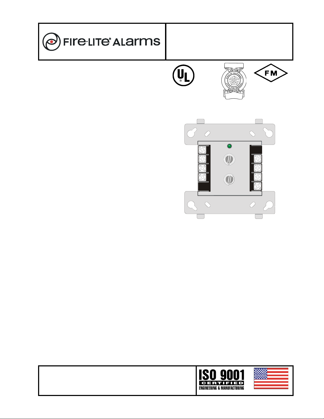
MMF-300 (Replaces M300) — The MMF-300 Moni-
tor Module is a standard-sized module (typically mounts to a
4" [101.6 mm] square box) that supervises either a Class A
(Style D) or Class B (Style B) circuit of dry-contact input devices.
MMF-301 (Replaces M301) — The MMF-301 is a Min-
iature Monitor Module (a mere 1.3" (33.02 mm) H x 2.75"
(69.85 mm) W x 0.5" (12.70 mm) D) used to supervise a
Class B (Style B) circuit. Its compact design allows the MMF301 to be mounted in a single-gang box behind the device it
is monitoring.
MMF-302 (Replaces M302) — The MMF-302 Inter-
face Module is a standard-sized module used to monitor and
supervise compatible two-wire, 24 volt, smoke detectors on
a Class A (Style D) or Class B (Style B) circuit.
MDF-300 (New) — The MDF-300 Dual Monitor Module
is a standard-sized module (typically mounts to a 4" [101.6
mm] square box) that supervises two Class B (Style B) circuits of dry-contact input devices.
MMF-300 MONITOR MODULEMMF-300 MONITOR MODULE
MMF-300 MONITOR MODULE
MMF-300 MONITOR MODULEMMF-300 MONITOR MODULE
• Built-in type identification automatically identifies this device as a monitor module to the control panel.
• Powered directly by two-wire SLC loop. No additional
power required.
• High noise (EMF/RFI) immunity.
• SEMS screws with clamping plates for ease of wiring.
• Direct Decade 01 – 99 (MS-9200) and 01-159 (MS-9600)
entry of address.
• LED flashes green during normal operation and latches
on steady red to indicate alarm.
The MMF-300 Monitor Module is intended for use in intelligent, two-wire systems, where the individual address of each
module is selected using the built-in rotary switches. It provides either a two-wire or four-wire Class A or Class B faulttolerant Initiating Device Circuit (IDC) for normally-open-contact fire alarm and supervisory devices. The module has a
panel-controlled LED indicator. The MMF-300 can be used
to replace M300 modules in existing systems.
MMF-300 Applications — Use to monitor a zone of
four-wire smoke detectors, manual fire alarm pull stations,
waterflow devices, or other normally-open dry-contact alarm
activation devices. May also be used to monitor normallyopen supervisory devices with special supervisory indication at the control panel. Monitored circuit may be wired as
an NFPA Style B (Class B) or Style D (Class D) Initiating
terminates the Style B circuit. No resistor is required for supervision of the Style D circuit. Maximum IDC resistance is
1,500 ohms.
MMF-300 Operation — Each MMF-300 uses one of
99 (MS-9200) or 159 (MS-9600) available module addresses
on an SLC loop. It responds to regular polls from the control
panel and reports its type and the status (open/normal/short)
of its Initiating Device Circuit (IDC). A flashing LED indicates
that the module is in communication with the control panel.
The LED latches steady on alarm (subject to current limitations on the loop).
MMF-300 Specifications
Nominal operating voltage: 15 to 32 VDC.
Maximum current draw: 5.1 mA (LED on).
Average operating current: 400 µA (LED flashing).
EOL resistance: 47K ohms.
Temperature range: 32°F to 120°F (0°C to 49°C).
Humidity range: 10% to 93% noncondensing.
Dimensions: 4.5" (114.3 mm) high x 4" (101.6 mm) wide x
1.25" (31.75 mm) deep. Mounts to a 4" (101.6 mm) square
x 2.125" (53.975 mm) deep box.
Device Circuit. A 47K ohm End-of-Line Resistor (provided)
This document is not intended to be used for installation purposes. We try to keep our
product information up-to-date and accurate. We cannot cover all specific applications or anticipate all requirements. All specifications are subject to change without
notice. For more information, contact Fire•Lite Alarms, One Fire-Lite Place, Northford,
Connecticut 06472. Phone: (800) 627-3473, Toll Free FAX: (877) 699-4105, FAX
Back:(888) 388-3299.
MMF-300, MMF-302 and MDF-300
Section: Addressable Devices
7300-0075:185
9
9
7
7
6
6
5
5
4
4
8
3
3
8
2
2
1
1
0
0
TENS
TENS
7
7
7
7
6
6
5
5
4
4
6
6
3
3
2
2
1
1
0
0
5
5
ONES
LOOP ADDRESS
LOOP
ONES
8
8
9
9
10
10
11
11
12
12
13
13
14
14
15
15
8
8
9
9
ADDRESS
0
0
1
1
2
2
3
3
4
4
Made in the U.S.A.
DF-52121 — Page 1 of 3
DF-52121 E-325
52121m300.wmf
Page 2
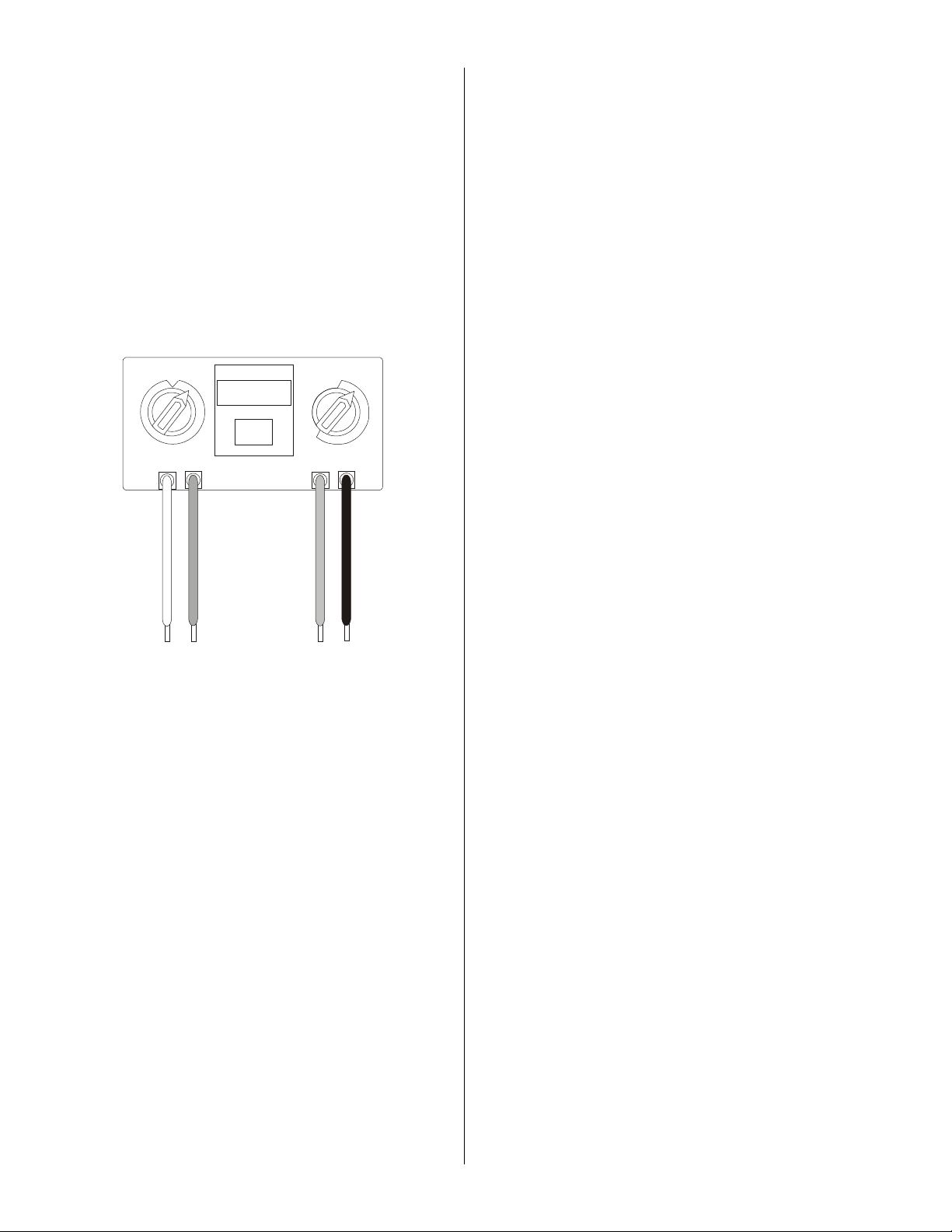
MMF-301 MINI MONITOR MODULEMMF-301 MINI MONITOR MODULE
MMF-301 MINI MONITOR MODULE
MMF-301 MINI MONITOR MODULEMMF-301 MINI MONITOR MODULE
• Built-in type identification automatically identifies this device as a monitor module to the MS-9200.
• Powered directly by two-wire SLC Loop. No additional
power required.
• High noise (EMF/RFI) immunity.
• Tinned, stripped leads for ease of wiring.
• Direct-dial entry of address (01-99).
The MMF-301 Mini Monitor Module can be installed in a
single-gang junction directly behind the monitored unit. Its
small size and light weight allow it to be installed without rigid
mounting. The MMF-301 is intended for use in intelligent,
two-wire systems where the individual address of each module is selected using rotary switches. It provides a two-wire
initiating device circuit for normally-open-contact fire alarm
and security devices. The MMF-301 can be used to replace
M301 module in existing systems.
1
2
3
4
5
6
ADDRESS
LOOP
9
8
ONES
0
1
2
3
4
5
6
7
MMF101-wired.wmf
12
11
13
10
14
9
0
15
7
8
TENS
MMF-301 Applications — Use to monitor a single de-
vice or a zone of four-wire smoke detectors, manual fire
alarm pull stations, waterflow devices, or other normally-open
dry-contact devices. May also be used to monitor normallyopen supervisory devices with special supervisory indication at the control panel. Monitored circuit/device is wired as
an NFPA Style B (Class B) Initiating Device Circuit. A 47K
ohm End-of-Line Resistor (provided) terminates the circuit.
MMF-301 Operation — Each MMF-301 uses one of
159 (MS-9600 only) available module addresses on an SLC
loop. It responds to regular polls from the control panel and
reports its type and the status (open/normal/short) of its Initiating Device Circuit (IDC).
MMF-301 Specifications
Nominal operating voltage: 15 to 32 VDC.
Average operating current: 375 µA maximum.
EOL resistance: 47K ohms.
Temperature range: 32°F to 120°F (0°C to 49°C).
Humidity range: 10% to 93% noncondensing.
Dimensions: 1.3" (33.02 mm) high x 2.75" (69.85 mm) wide
x 0.5" (12.70 mm) deep.
Wire length: 6" (152.4 mm) minimum.
Page 2 of 3 — DF-52121
MMF-302 INTERFACE MODULEMMF-302 INTERFACE MODULE
MMF-302 INTERFACE MODULE
MMF-302 INTERFACE MODULEMMF-302 INTERFACE MODULE
• Supports compatible two-wire smoke detectors.
• Supervises IDC wiring and connection of external power
source (resettable).
• High noise (EMF/RFI) immunity.
• SEMS screws with clamping plates for ease of wiring.
• Direct-dial entry of address (01-99).
• LED flashes during normal operation (this is a programmable option).
• LED latches steady to indicate alarm on command from
control panel.
The MMF-302 Interface Module is intended for use in intelligent, addressable systems, where the individual address
of each module is selected using built-in rotary switches. This
module allows intelligent panels to interface and monitor twowire conventional smoke detectors. It transmits the status
(normal, open, or alarm) of one full zone of conventional detectors back to the control panel. All two-wire detectors being monitored must be UL compatible with the module.
MMF-302 Applications — Use the MMF-302 to moni-
tor a zone of two-wire smoke detectors. The monitored circuit may be wired as an NFPA Style B (Class B) or Style D
(Class A) Initiating Device Circuit. A 3.9 K ohm End-of-Line
Resistor (provided) terminates the end of the Style B or D
(class B or A) circuit (maximum IDC loop resistance is 25
ohms). Install ELR across terminals 8 and 9 for Style D application.
MMF-302 Operation — Each MMF-302 uses one of
159 (MS-9600 only) available module addresses on an SLC
loop. It responds to regular polls from the control panel and
reports its type and the status (open/normal/short) of its Initiating Device Circuit (IDC). A flashing LED indicates that
the module is in communication with the control panel. The
LED latches steady on alarm (subject to current limitations
on the loop).
MMF-302 Specifications
Nominal operating voltage: 15 to 32 VDC.
Maximum current draw: 5.1 mA (LED on).
Average operating current: 270 µA (LED flashing).
EOL resistance: 3.9K ohms.
External supply voltage
DC voltage:
18 to 28 volts power limited.
0.1 VRMS maximum.
Temperature range: 32°F to 120°F (0°C to 49°C).
Humidity range: 10% to 93% noncondensing.
Dimensions: 4.5" (114.3 mm) high x 4" (101.6 mm) wide x
1.25" (31.75 mm) deep. Mounts to a 4" (101.6 mm) square
x 2.125" (53.975 mm) deep box.
MDF-300 DUAL MONITOR MODULEMDF-300 DUAL MONITOR MODULE
MDF-300 DUAL MONITOR MODULE
MDF-300 DUAL MONITOR MODULEMDF-300 DUAL MONITOR MODULE
• Built-in type identification automatically identifies this device as two monitor modules to the control panel.
• Powered directly by the two-wire SLC loop. No additional
power required.
• High noise (EMF/RFI) immunity.
• SEMS screws with clamping plates for ease of wiring.
• Direct-dial entry of address 01 – 159 on the MS-9600.
• LED flashes green during normal operation and latches
on steady red to indicate alarm.
The MDF-300 Dual Monitor Module is intended for use in
intelligent, two-wire systems, where the individual address
of each module is selected using the built-in rotary switches.
It provides two independant two-wire fault-tolerant Initiating
Device Circuits (IDCs) at two separate, consecutive ad-
(between Terminals T3 and T4):
Ripple voltage:
Current:
90 mA per module maximum.
Page 3

dresses. It is capable of monitoring normally open-contact
fire alarm and supervisory devices, or either normally open
or normally closed security devices. The module has a single
panel-controlled red LED indicator.
MDF-300 Applications - Use to monitor a zone of four-
wire smoke detectors, manual fire alarm pull stations,
waterflow devices, or other normally-open dry-contact alarm
activation devices. May also be used to monitor normallyopen supervisory devices with special supervisory indication at the control panel. Monitored circuit may be wired as
an NFPA Style B (Class B) Initiating Device Circuit. The
47K ohm End-of-Line Resistors (provided) terminate the Style
B circuit. Maximum IDC resistance is 1,500 ohms.
MDF-300 Operation - Each MDF-300 uses two of 99
(MS-9200) or 159 (MS-9600) available module addresses
on an SLC loop. It responds to regular polls from the control
panel and reports its type and the status (open/normal/short)
of its Initiating Device Circuit (IDC). A flashing LED indicates
that the module is in communication with the control panel.
The LED latches steady on alarm (subject to current limitations on the loop).
MDF-300 Specifications
Nominal operating voltage: 15 to 32 VDC.
Maximum current draw: 5.1 mA (LED on).
Average operating current: 750 µA (LED flashing).
EOL resistance: 47K ohms.
Maximum IDC wire resistance: 1,500 Ohms.
Temperature range: 32°F to 120°F (0°C to 49°C).
Humidity range: 10% to 93% noncondensing.
Dimensions: 4.5" (114.3 mm) high x 4" (101.6 mm) wide x
1.25" (31.75 mm) deep. Mounts to a 4" (101.6 mm) square x
2.125" (53.975 mm) deep box.
Accessories: SMB500 electrical box.
PRODUCT LINE INFORMATIONPRODUCT LINE INFORMATION
PRODUCT LINE INFORMATION
PRODUCT LINE INFORMATIONPRODUCT LINE INFORMATION
MMF-300 Monitor Module.
MMF-301 Mini Monitor Module.
MMF-302 Two-Wire Detector Monitor Module.
MDF-300 Dual Monitor Module.
SMB500 Optional Surface-Mount Backbox.
MOUNTING DIAGRAMSMOUNTING DIAGRAMS
MOUNTING DIAGRAMS
MOUNTING DIAGRAMSMOUNTING DIAGRAMS
for standard-sized modules
INSTALLATIONINSTALLATION
INSTALLATION
INSTALLATIONINSTALLATION
MMF-300, MMF-302
to a standard 4" (101.6 mm) square, 2.125" (53.975 mm)
deep, electrical box. They may also be mounted to the
SMB500 surface-mount box. Mounting hardware and installation instructions are provided with each module. All wiring
must conform to applicable local codes, ordinances, and regulations. These modules are intended for power-limited wiring only.
The
MMF-301
without rigid connections inside a standard electrical box. All
wiring must conform to applicable local codes, ordinances,
and regulations.
ARCHITECTS’/ENGINEERS’ARCHITECTS’/ENGINEERS’
ARCHITECTS’/ENGINEERS’
ARCHITECTS’/ENGINEERS’ARCHITECTS’/ENGINEERS’
SPECIFICATIONSSPECIFICATIONS
SPECIFICATIONS
SPECIFICATIONSSPECIFICATIONS
Specifications of these and all Fire•Lite Alarms products
are available from Fire•Lite Alarms.
and
MDF-300
module is intended to be wired and mounted
modules mount directly
52121mt1.wmf
DF-52121 — Page 3 of 3
 Loading...