

Page 1

Addressable Fire Alarm Control Panel
ES-200X
ES-200XC
Manual
Document LS10131-000FL-E Rev: C
7/25/2018 ECN:18-323
Page 2

Fire Alarm & Emergency Communication System Limitations
While a life safety system may lower insurance rates, it is not a substitute for life and property insurance!
An automatic fire alarm system—typically made up of smoke
detectors, heat detectors, manual pull stations, audible warning
devices, and a fire alarm control panel (FACP) with remote notification capability—can provide early warning of a d eveloping fire. Such
a system, however, doe s not assure protection against property
damage or loss of life resulting from a fire.
An emergency communication system—typically made up of an
automatic fire alarm system (as described above) and a life safety
communication system that may include an autonomous control
unit (ACU), local operating console (LOC), voice communication,
and other various interoperable communication methods—can
broadcast a mass notification message. Such a system, however,
does not assure protection against property damage or loss of life
resulting from a fire or life safety event.
The Manufacturer recommends that smoke and/or heat detectors
be located throughout a protected premises following the
recommendations of the current edition of the National Fire
Protection Association Standard 72 (NFPA 72), manufacturer's
recommendations, State and local codes, and the
recommendations contained in the Guide for Proper Use of Sys tem
Smoke Detectors, which is made available at no charge to all
installing dealers. This document can be found at http://
www.systemsenso r.com/appguides/. A study by the Federal
Emergency Management Agency (an agency of the United States
government) indicated that smoke detectors may not go off in as
many as 35% of all fires. While fire alarm systems are designed to
provide early warning against fire, they do not guarantee warni ng or
protection against fire. A fire alarm system may not provide timely or
adequate warning, or simply may not function, for a variety of
reasons:
Smoke detectors may not sense fire where smoke cannot reach
the detectors such as in chimneys, in or behind walls, on roofs, or
on the other side of closed doors. Smoke detectors also may not
sense a fire on another level or floor of a building. A second-floor
detector, for example, may not sense a first-floor or basement fire.
Particles of combustion or “smoke” from a developing fire may
not reach the sensing chambers of smoke detectors because:
• Barriers such as closed or partially closed doors, walls, chimneys, even wet or humid areas may inhibit particle or smoke
flow.
• Smoke particles may become “cold,” stratify, and not reach the
ceiling or upper walls where de t ec t ors are located.
• Smoke particles may be blown away fr om detectors by air outlets, such as air conditioning vents.
• Smoke particles may be drawn into air returns before reaching
the detector.
The amount of “smoke” present may be insufficient to alarm smoke
detectors. Smoke detectors are designed to alarm at various level s
of smoke density. If such density levels are not created by a developing fire at the location of detectors, the detectors will not go into
alarm.
Smoke detectors, even when working properly, have sensing limitations. Detectors that have photoelectronic sensing chambers tend
to detect smoldering fires better than flaming fires, which have little
visible smoke. Detectors that have ionizing-type sensing chambers
tend to detect fast-flaming fires better than smoldering fires.
Because fires develop in different ways and are often unpredictable
in their growth, neither type of detector is necessarily best and a
given type of detector may not provide adequate warning of a fire.
Smoke detectors cannot be expected to provide adequate warning
of fires caused by arson, children playing with matches (especially
in bedrooms), smoking in bed, and violent explosions (caused by
escaping gas, improper storage of flammable materials, etc.).
Heat detectors do not sense particles of combustion and alarm
only when heat on their sensors increases at a predetermined rate
or reaches a predetermined level. Rate-of-rise heat detectors may
be subject to reduced sensitivity over time. For this reason, the rateof-rise feature of each detector should be tested at least once per
year by a qualified fire protection specialist. Heat detectors are
designed to protect property, not life.
IMPORTANT! Smoke detectors must be installed in the same
room as the control panel and in rooms used by the system for the
connection of alarm transmission wiring, communications, signaling, and/or power. If detectors are not so located, a developing fire
may damage the alarm system, compromising its ability to report a
fire.
Audible warning devices such as bells, horns, strobes, speakers and displays may not alert people if these devices are located
on the other side of closed or partly open doors or are located on
another floor of a building. Any warning device may fail to alert people with a disability or those who have recently consumed drugs,
alcohol, or medication. Please note that:
• An emergency communication system may take priority over a
fire alarm system in the event of a life safety emergency.
• Voice messagi ng systems must be designed t o meet intelligibili ty
requirements as defined by NFPA, local codes, and Authorities
Having Jurisdiction (AHJ).
• Language and instructional requirements must be clearly disseminated on any local displays.
• Strobes can, under certain circumstances, cause seizures in
people with conditions such as epilepsy.
• Studies have shown that certain people, even when they hear a
fire alarm signal, do not respond to or comprehend the meaning
of the signal. Audib le devices, such as h orns and bell s, can hav e
different tonal patterns and frequencies. It is the property
owner's responsibility to conduct fire drills and other training
exercises to make people aware of fire alarm signals and
instruct them on the proper reaction to alarm signals.
• In rare instances, the sounding of a warning device can cause
temporary or permanent hearing loss.
A life safety system will not operate without any e lectrical power. If
AC power fails, the system will operate from standby batteries only
for a specified time and only if the batteries have been properly
maintained and replaced regularly.
Equipment used in the system may not be technically c ompatible
with the control panel. It is e ssential to use only equipment listed f or
service with your control panel.
Telephone lines needed to transmit alarm signals from a premises
to a central monitoring station may be out of service or temporarily
disabled. For added protection against telephone line failure,
backu
p radio transmission systems are recommended.
The most common cause of life safety system malfuncti on i s i na dequate maintenance. To keep the entire life safety system in excellent working order, ongoing maintenance is required per the
manufacturer's recommendations, and UL and NFPA standards. At
a minimum, the requirements of NFPA 72 shall be followed. Environments with large amounts of dust, dirt, or high air velocity require
more frequent maintenance. A maintenance agreement should be
arranged through the local manufacturer's representative. Maintenance should be scheduled as required by National and /or lo cal fire
codes and should be performed by authorized professional life
safety system installers only. Adequate written records of all inspections should be kept.
Limit-D2-2016
2 ES-200X Series Manual — P/N LS10131-000FL-E:C 7/25/2018
Page 3

Installation Precautions
Adherence to the following will aid in problem-free installation with long-term reliability:
WARNING - Several different sources of power can be connected to the fire alarm control panel. Disconnect all sourc es of
power before servicing. Control unit and associated equipment
may be damaged by removing and/or inserting cards, modules, or
interconnecting cables while the unit is energized. Do not attempt
to install, service, or operate this unit until manuals are read and
understood.
CAUTION - System Re-acceptance Test after Software
Changes: To ensure proper system operation, this product must be
tested in accordance with NFPA 72 after any programming operation or change in site-specific software. Re-acceptance testing is
required after any change, addition or deletion of syst em components, or after any modification, repair or adjustment to system
hardware or wiring. All components, circuits, system operations, or
software functions known to be aff ected by a change must b e 100%
tested. In addition, to ensure that other operations are not inadvertently affected, at least 10% of initiating devices that are not directly
affected by the change, up to a maximum of 50 devices, must also
be tested and proper system operation verified.
This system meets NFPA requirements for operation at 0-49º C/
32-120º F and at a relative humidity . However, the useful life of
the system's standby batteries and the electro nic compo nent s may
be adversely affected by extreme temperature ranges and humidity .
Therefore, it is recommended that this system and its peripherals
be installed in an environment with a normal room temperature of
15-27º C/60-80º F.
Verify that wire sizes are adequate for all initiating and indicating
device loops. Most devices cannot tolerate more than a 10% I.R.
drop from the specified device voltage.
Like all solid state electronic devices, this system may operate
erratically or can be damaged when subjected to lightning induced
transients. Although no system is completely immune from lightning transients and interference, pr oper grounding will reduce susceptibility. Overhead or outside aerial wiring is not recommended,
due to an increased susceptibility to nearby lightning strikes. Consult with the Technical Services Department if any problems are
anticipated or encountered.
Disconnect AC power and batteries prior to removing or inserting
circuit boards. Failure to do so can damage circuits.
Remove all electronic assemblies prior to any drilling, filing,
reaming, or punching of the enclosure. When possible, make all
cable entries from the sides or rear. Before making modifications,
verify that they will not interfere with battery, transformer, or pri nt ed
circuit board location.
Do not tighten screw terminals more than 9 in-lbs. Over-tightening may damage threads, resulting in reduced terminal contact
pressure and difficulty with screw terminal removal.
This system contains static-sensitive components. Always
ground yourself with a proper wrist strap before handling any circuits so that static charges are removed from the body. Use static
suppressive packaging to protect electronic assemblies removed
from the unit.
Follow the instructions in the installation, operating, and programming manuals. These instructions must be followed to avoid
damage to the control panel and associated equipment. FACP
operation and reliability depend upon proper installation.
Precau-D1-9-2005
FCC Warning
WARNING: This equipment generates, uses, and can radi-
ate radio frequency energy and if not installed and used in
accordance with the instruction manual may cause interference to radio communications. It has been tested and foun d
to comply with the limits for class A computing devices pursuant to Subpart B of Part 15 of FCC Rules, which is
designed to provide reasonable protection against such
interference when devices are operated in a commercial
environment. Operation of this equipment in a residential
area is likely to cause interference, in which case the user
will be required to correct the interference at his or her own
expense.
Canadian Requirements
This digital apparatus does not exceed the Class A limits for
radiation noise emissions from digital apparatus set out in
the Radio Interference Regulations of the Canadian Department of Communications.
Le present appareil numerique n'emet pas de bruits radioelectriques depassant les limites applicables aux appareils
numeriques de la classe A prescrites dans le Reglement sur
le brouillage radioelectrique edicte par le ministere des
Communications du Canada.
LiteSpeed™ and Lite-Connect™ are trademarks; and Fire-Lite® Alarms, Honeywell®, and SWIFT® are registered trademarks of Honeywell International Inc.
Microsoft® and Windows® are registered trademarks of the Microsoft Corporation. Chrome™ and Google™ are trademarks of Google Inc. Firefox® is a registered
trademark of The Mozilla Foundation.
©2018 by Honeywell International Inc. All rights reserved. Unauthorized use of this document is strictly prohibited.
ES-200X Series Manual — P/N LS10131-000FL-E:C 7/25/2018 3
Page 4

Software Downloads
In order to supply the latest features and functionality in fire alarm and life safety technology to our customers, we make frequent
upgrades to the embedded software in our products. To ensure that you are installing and programming the latest features, we
strongly recommend that you download the most current version of software for each product prior to commissioning any system.
Contact Technical Support with any questions about softwa re and the app rop riate version for a specific application.
Documentation Feedback
Your feedback helps us keep our documentation up-to-date and accurate. If you have any comments or suggestions about our online
Help or printed manuals, you can email us.
Please include the following information:
• Product name and version number (if applicable)
• Printed manual or online Help
• T opic Title (for online Help)
• Page number (for printed manual)
• Brief description of content you think should be improved or corrected
• Your suggestion for how to correct/improve documentation
Send email messages to:
FireSystems.TechPubs@honeywell.com
Please note this email address is for documentation feedback only. If you have any technical issues, please contact Technical
Services.
4 ES-200X Series Manual — P/N LS10131-000FL-E:C 7/25/2018
Page 5

Table of Contents
Section 1: Product Description...................................................................................................................................... 13
1.1: Features and Options .......................................................................................................................................................................................13
1.2: Specifications...................................................................................................................................................................................................14
1.3: Controls and Indicators....................................................................................................................................................................................16
1.4: Components.....................................................................................................................................................................................................16
1.4.1: Intelligent Addressable Detectors.........................................................................................................................................................17
1.4.2: Intelligent Addressable Modules..........................................................................................................................................................17
1.4.3: Addressable Device Accessories..........................................................................................................................................................17
End-of-Line Resistor Assembly..............................................................................................................................................................17
Power Supervision Relay........................................................................................................................................................................17
EOL-C(R/W) Mounting Plate.................................................................................................................................................................17
1.5: Optional Modules ............................................................................................................................................................................................17
1.6: Accessories ......................................................................................................................................................................................................18
1.6.1: FS-Tools Programming Utility.............................................................................................................................................................18
1.6.2: Dress Panel ....................... ............................ ... ............................. ........................................................................................................18
1.6.3: Trim Ring............ ............................. ............................. .. ............................. ...........
1.6.4: Battery Box........... ... ............................. ............................. ............................ .......................................................................................18
BB-26......................................................................................................................................................................................................18
BB-55F....................................................................................................................................................................................................18
1.6.5: Battery Charger. .. ............................. .......................................................... ...........................................................................................18
CHG-75 Battery Charger........................................................................................................................................................................18
CHG-120F Battery Charger....................................................................................................................................................................19
1.6.6: ECC-50/100..........................................................................................................................................................................................19
1.6.7: ECC-FFT .................................................... ............................. ............................. ................................................................................19
1.6.8: W-GATE Wireless Gateway .......................................... ......................................................................................................................19
1.6.9: ANN-BUS Annunciators/Modules............................. .. .......................................................... .. ............................................................19
Guidelines...............................................................................................................................................................................................19
ANN-80/ANN-100 Remote Fire Annunciators......................................................................................................................................19
ANN-S/PG Serial/Parallel Interface Module..........................................................................................................................................19
ANN-I/O LED Driver Module ...............................................................................................................................................................20
ANN-LED Annunciator Module............................................................................................................................................................20
ANN-RLY Annunciator Module............................................................................................................................................................20
1.7: Getting Started.................................................................................................................................................................................................20
1.8: Telephone Requirements and Warnings...........................................................................................................................................................20
Telephone Circuitry..................................................................................... .. .......................................................................................20
1.8.1:
1.8.2: Telephone Company Rights and Warnings..........................................................................................................................................21
1.8.3: For Canadian Applications ...................................................................................................................................................................21
Section 2: Installation ....................................... ... .... ... ... ... ... .... ... ... ... .... ... ... ... .... ... ... ... ... ................................................. 22
2.1: Mounting the Backbox ....................................................................................................................................................................................22
2.2: Power...............................................................................................................................................................................................................25
2.2.1: AC Power and Earth Ground Connection ............................................................................................................................................25
2.2.2: Battery Power ..................... .. ............................. ............................. ......................................................................................................25
2.2.3: Special Application DC Power Output Connection ........................................... .. ................................................................................26
2.3: Relays ..............................................................................................................................................................................................................26
2.4: Notification Appliance Circuits.......................................................................................................................................................................26
2.4.1: Class B NAC Wiring .................................. .. ............................. ... ............................. ...........................................................................27
2.4.2: Class A NAC Wiring..... ....................................................................................... .. ..............................................................................27
2.5: Remote Synchronization Output......................................................................................................................................................................28
2.6: UL Power-limited Wiring Requirements.........................................................................................................................................................29
2.7: IPOTS-COM Communicator...........................................................................................................................................................................30
Wiring.....................................................................................................................................................................................................30
Dip Switches...........................................................................................................................................................................................30
2.8: Optional Module Installation...........................................................................................................................................................................31
2.8.1: CELL-CAB-FL/CELL-MOD................................................ .. .............................................................................................................31
Installation ..............................................................................................................................................................................................31
Wiring.....................................................................................................................................................................................................31
2.8.2: PWRMOD24 NAC Expander...............................................................................................................................................................31
Installation and Wiring ...........................................................................................................................................................................31
2.8.3: 4XTMF Transmitter Module Installation.............................................................................................................................................31
2.8.4: ANN-BUS Annunciators/Modules............................. .. .......................................................... .. ............................................................33
..............................................................................18
ES-200X Series Manual — P/N LS10131-000FL-E:C 7/25/2018 5
Page 6

Table of Contents
ANN-BUS Wiring ..................................................................................................................................................................................33
ANN-BUS Device Addressing...............................................................................................................................................................36
ANN-80 Remote Fire Annunciator.........................................................................................................................................................36
ANN-100 Remote Fire Annunciator.......................................................................................................................................................38
ANN-S/PG Serial/Parallel Interface Module..........................................................................................................................................39
ANN-I/O LED Driver Module ...............................................................................................................................................................41
ANN-LED Annunciator Module............................................................................................................................................................43
ANN-RLY Annunciator Module............................................................................................................................................................45
2.8.5: Printer ............... ............................. ............................. ............................. .............................................................................................46
Printer Configuration..............................................................................................................................................................................46
2.8.6: ECC-FFT Firefighter Telephone ..........................................................................................................................................................47
W-GATE Wireless Gateway ................ .. ............................. .................................................................................................................47
2.8.7:
2.9: Automatic Audio Panel Control.......................................................................................................................................................................47
Section 3: Programming................................................................ ... .... ... ... ... .... ... ... ... ... .... ... .......................................... 49
3.1: Programming Data Entry.................................................................................................................................................................................49
3.2: User Programming...........................................................................................................................................................................................50
3.3: Initial Power-up ...............................................................................................................................................................................................51
3.4: Programming Screens Description ..................................................................................................................................................................51
3.5: Programming and Passwords...........................................................................................................................................................................51
3.6: Master Programming Level.............................................................................................................................................................................52
3.6.1: Autoprogram......... ................................................................................................................................................................................52
3.6.2: Point Program.......................................................................................................................................................................................53
Detector Programming............................................................................................................................................................................53
Module Programming.............................................................................................................................................................................60
3.6.3: Zone Setup................................ ............................. ............................. ..................................................................................................68
Enable .....................................................................................................................................................................................................68
Disable ....................................................................................................................................................................................................68
Special Purpose Zone..............................................................................................................................................................................69
s Installed........................................................................................................................................................................................69
Zone
Zones Enabled.........................................................................................................................................................................................69
Zones Disabled .......................................................................................................................................................................................69
Zone Type...............................................................................................................................................................................................70
Zones Available ......................................................................................................................................................................................70
Zone Message .........................................................................................................................................................................................70
3.6.4: Loop Setup............................................................................................................................................................................................71
Class........................................................................................................................................................................................................71
Loop Protocol .........................................................................................................................................................................................71
Device Addressing..................................................................................................................................................................................71
3.6.5: System Setup ........................................ ............................. ............................ .......................................................................................71
Function Keys............................................... ........................................................ ..................................................................................72
Banner.....................................................................................................................................................................................................73
Time-Date...............................................................................................................................................................................................73
Timers.....................................................................................................................................................................................................74
NAC (Notification Appliance Circuit) ........................... ............................. .. ............................. .. ..........................................................76
Relays......................................................................................................................................................................................................78
Canadian Option .....................................................................................................................................................................................79
Waterflow Silenceable..... ... ............................ ............................. ............................. ..............................................................................79
MNS Override................ ............................. .. ............................. .. ............................. ..............................................................................80
Auxiliary Power......................................................................................................................................................................................80
Trouble Reminder...................................................................................................................................................................................80
Language.................................................................................................................................................................................................80
Charger Enable ................ ... ............................ ............................. ............................. ..............................................................................80
4XTMF Supervision ...............................................................................................................................................................................80
Remote Sync Enable...............................................................................................................................................................................80
3.6.6: History ...................................................... ............................. ............................. ..................................................................................81
View Events............ ............................. ............................. ............................. .........................................................................................81
Erase History...........................................................................................................................................................................................81
3.6.7: Communicator ........................ ............................. .. ............................. ..................................................................................................81
Communicator Installed..........................................................................................................
POTS Settings..................... ............................ ............................. ...........................................................................................................82
IP Settings...............................................................................................................................................................................................83
................................................................81
6 ES-200X Series Manual — P/N LS10131-000FL-E:C 7/25/2018
Page 7

Table of Contents
Primary and Secondary Communication Paths ......................................................................................................................................84
Trouble Report Limit (Dialer Runaway Prevention)..............................................................................................................................86
Report Style ............................................................................................................................................................................................87
Event Codes...................................................................... ......................................................................................................................87
3.6.8: Annunciators................ ............................. .. ............................. .. ............................. ..............................................................................90
ANN-BUS Setup....................................................................................................................................................................................90
ANN-BUS Options.................................................................................................................................................................................97
3.6.9: Password Change..................................................................................................................................................................................99
Invalid Password..................... .. ............................. ............................. ............................. .......................................................................99
3.6.10: Clear Program...................................................................................................................................................................................100
3.6.11: Program Check .................................................................................................................................................................................100
3.7: Maintenance Programming Level..................................................................................................................................................................101
3.7.1: Disable Point. ............................ ... ............................. ..........................................................................................................................101
3.7.2: History ...................................................... ............................. ............................. ................................................................................102
3.7.3: Program Check .................................................... .. ............................. ... .............................................................................................102
3.7.4: Walktest......................................... ............................. ............................. .. .........................................................................................103
3.7.5: System............. ............................. ............................. ............................. .............................................................................................104
3.7.6: Zone Setup................................ ............................. ............................. ................................................................................................104
Section 4: Operating Instructions................................................................................................................................ 106
4.1: Panel Control Buttons....................................................................................................................................................................................106
4.1.1: Acknowledge......................................................................................................................................................................................106
4.1.2: Alarm Silence ............................................... ............................. ............................. ............................................................................106
4.1.3: Drill/Hold 2 Sec..................................................................................................................................................................................106
4.1.4: Reset ................. ............................. .. ............................. ............................. .........................................................................................106
4.1.5: Function Keys F1-F4..........................................................................................................................................................................106
4.2: LED Indicators...............................................................................................................................................................................................106
4.3: Normal Operation ..........................................................................................................................................................................................107
4.4: Trouble Operation..........................................................................................................................................................................................107
4.5: Alarm Operation ............................................................................................................................................................................................108
4.6: CO Alarm Operation......................................................................................................................................................................................109
4.7: Supervisory Operation...................................................................................................................................................................................109
4.8: Process Monitor Operation............................................................................................................................................................................110
4.9: Hazard/Tornado Condition Operation...........................................................................................................................................................110
4.10: Medical Alert Condition Operation.............................................................................................................................................................110
4.11: Mass Notification Operation... ... ............................ ... ......................................................... ..........................................................................111
4.12: NAC Operation............................................................................................................................................................................................111
4.13: Programmed Zone Operation ......................................................................................................................................................................111
4.14: Disable/Enable Operation............................................................................................................................................................................111
4.15: Waterflow Circuits Operation......................................................................................................................................................................111
4.16: Detector Functions.......................................................................................................................................................................................111
4.17: Time Functions: Real-Time Clock................... ............................. .. ............................. .. ..............................................................................112
4.18: Synchronized NAC Operation.....................................................................................................................................................................112
4.19: Coded Operation..........................................................................................................................................................................................112
4.20: Presignal ......................................................................................................................................................................................................112
4.21: Positive Alarm Sequence.............................................................................................................................................................................112
4.22: Special System Timers.................................................................................................................................................................................113
4.22.1: Silence Inhibit Timer........................................................................................................................................................................113
Autosilence Timer ............................................................................................................................................................................113
4.22.2:
4.22.3: Trouble Reminder.............................................................................................................................................................................113
4.22.4: Waterflow Retard Timer...................................................................................................................................................................113
4.22.5: Alarm Verification (None or One Minute). ... ............................... ....................................................................................................113
4.22.6: Control Module Delay Timer ...........................................................................................................................................................114
4.23: Walktest........................................................................................................................................................................................................114
4.24: Read Status ..................................................................................................................................................................................................114
4.24.1: System Point .....................................................................................................................................................................................114
4.24.2: Zones.................................................................................................................................................................................................115
4.24.3: Trouble Reminder.............................................................................................................................................................................116
4.24.4: Timers...............................................................................................................................................................................................116
4.24.5: NACs ................................................................................................................................................................................................116
4.24.6: Relays ...............................................................................................................................................................................................116
4.24.7: Program Check .................................................................................................................................................................................116
ES-200X Series Manual — P/N LS10131-000FL-E:C 7/25/2018 7
Page 8

Table of Contents
4.24.8: History ..............................................................................................................................................................................................117
4.24.9: Annunciators.....................................................................................................................................................................................117
4.24.10: Communicator ................................................................................................................................................................................117
4.24.11: Print.................................................................................................................................................................................................118
Chamber Value .....................................................................................................................................................................................119
Drift Compensation...............................................................................................................................................................................119
Maintenance Alert.................................................................................................................................................................................119
4.24.12: Time-Date.......................................................................................................................................................................................120
4.24.13: Battery Charger...............................................................................................................................................................................120
4.24.14: 4XTM Supervision .........................................................................................................................................................................120
4.24.15: Remote Sync...................................................................................................................................................................................120
Section 5: Central Station Communications - POTS Transmission ......................................................................... 121
5.1: Transmittal Priorities .....................................................................................................................................................................................121
Section 6: FS-Tools Upload/Download........................................................................................................................ 123
6.1: FS-Tools Upload/Download..........................................................................................................................................................................123
6.2: Transferring a Program..................................................................................................................................................................................123
6.2.1: Security Features ................................................................... .............................................................................................................124
Secret Code Verification.................................................................................. .....................................................................................124
Time-out at Control Panel.....................................................................................................................................................................124
Error Checking......................................................................................................................................................................................124
Central Station Data Protection ............................................................................................................................................................124
Section 7: USB Upload/Download ............................................................................................................................... 125
7.1: USB Upload/Download.................................................................................................................................................................................125
Section 8: Firmware Upgrade....................................................................................................................................... 127
8.1: Firmware Upgrade.........................................................................................................................................................................................127
Section 9: Power Supply Calculations ........................................................................................................................ 128
9.1: Overview........................................................................................................................................................................................................128
9.2: Calculating the AC Branch Circuit................................................................................................................................................................128
9.3: Calculating the System Current Load............................................................................................................................................................128
9.3.1: Overview........................................ ............................. .. ............................. .........................................................................................128
9.3.2: How to Calculate System Current Load.............................................................................................................................................128
9.4: Calculating the Battery Size ..........................................................................................................................................................................130
9.4.1: NFPA Battery Requirements ................................................................. .. ............................ ...............................................................130
9.4.2: Selecting and Locating Batteries........................................................................................................................................................130
Appendix A: Software Zones........................................................................................................................................ 131
A.1: Correlations...................................................................................................................................................................................................131
Appendix B: Default Programming.............................................................................................................................. 138
Appendix C: NFPA Standard-Specific Requirements................................................................................................ 139
C.1: MBT-1 Municipal Box Trip - Silenceable ....................................................................................................................................................142
Appendix D: Wire Requirements.................................................................................................................................. 143
D.1: NAC Wiring..................................................................................................................................................................................................144
Appendix E: HVAC Control...........................................................................................................................................145
E.1: Control Module Operation............................................................................................................................................................................145
E.1.1: HVAC SHUTDOWN.........................................................................................................................................................................145
E.2: Monitor Module Operation ...........................................................................................................................................................................146
E.2.1: HVAC RESTART..............................................................................................................................................................................146
E.2.2: HVAC OVRRIDE..............................................................................................................................................................................146
Appendix F: Ademco Contact ID Format Event Code Descriptions.........................................................................147
F.1: Transmission Format Between DACT and Receiver.....................................................................................................................................147
F.2: Ademco Contact ID Typical Printout.............................................................................................................................................................147
8 ES-200X Series Manual — P/N LS10131-000FL-E:C 7/25/2018
Page 9

Table of Contents
Appendix G: Central Station Points............................................................................................................................. 152
Appendix H: NFPA Requirements................................................................................................................................ 154
Appendix I: Open/Short/Ground Trip Values.............................................................................................................. 155
Appendix J: Canadian Applications ............................................................................................................................ 156
Index............................................................................................................................................................................... 159
Slide-in Labels ...................................... ... .... ... ... ... .... ... ... ... ... .... ... ... ... .... ... ... .................................................................. 163
ES-200X and ES-200XC Fire Alarm Control Panels Operating Instructions............................................................ 165
ES-200X Series Manual — P/N LS10131-000FL-E:C 7/25/2018 9
Page 10

It is imperative that the installer understand the requirements of the Authority Having Jurisdiction (AHJ) and be familiar with the standards set forth by the following regulatory agencies:
• Underwriters Laboratories/Underwriters Laboratories Canada
• National Fire Protection Association
Before proceeding, the installer should be familiar with the following documents.
NFPA Standards
NFPA 72 National Fire Alarm Code
NFPA 70 National Electrical Code
NFPA 720 Carbon Monoxide Detection and Warning Equipment
Underwriters Laboratories Documents:
UL 38 Manually Actuated Signaling Boxes
UL 217 Smoke Detectors, Single and Multiple Station
UL 228 Door Closers–Holders for Fire Protective Signaling Systems
UL 268 Smoke Detectors for Fire Protective Signaling Systems
UL 268A Smoke Detectors for Duct Applications
UL 346 Waterflow Indicators for Fire Protective Signaling Systems
UL 464 Audible Signaling Appliances
UL 521 Heat Detectors for Fire Protective Signaling Systems
UL 864 Standard for Control Units for Fire Protective Signaling Systems
UL 1481 Power Supplies for Fire Protective Signaling Systems
UL 1638 Visual Signaling Appliances
UL 1971 Signaling Devices for Hearing Impaired
UL 2017 General-Purpose Signaling Devices and Systems
UL 2075 Standard for Gas and Vapor Detector and Sensors
UL 2572 Communication and Control Units for Mass Notification Systems
CAN/ULC - S524-01 Standard for Installation of Fire Alarm Systems
CAN/ULC - S559-04 Equipment for Fire Signal Receiving Centers and Systems
CAN/ULC - S561-03 Installation and Services for Fire Signal Receiving Centers and Systems
CAN/ULC - S527-99 Standard for Control Units for Fire Alarm Systems
This Class (A) digital apparatus complies with Canadian ICES-003.
Cet appareil numérique de la classe (A) est conforme à la norme NMB-003 du Canada.
Other:
Canadian Electrical Code, Part I
EIA-232E Serial Interface Standard
EIA-485 Serial Interface Standard
NEC Article 250 Grounding
NEC Article 300 Wiring Methods
NEC Article 760 Fire Protective Signaling Systems
Applicable Local and State Building Codes
Requirements of the Local Authority Having Jurisdiction (LAHJ)
Fire-Lite Documents:
Fire-Lite Device Compatibility Document #15384
SLC Wiring Manual Document #51309
ECC-50/100 Manual Document #LS10001-000FL-E
ECC-FFT Manual Document #LS10031-000FL-E
Wireless Gateway Manual Document #LS10036-000FL-E
CHG-120F Battery Charger Document #50888
CHG-75 Battery Charger Document #51315
IPOTS-COM POTS/IP Communicator Document #LS10184-000GE-E
PWRMOD24 NAC Power Module Document #LS10185-000GE-E
CELL-CAB-FL GSM Communicator Document #LS10186-000FL-E
ANN-80 Product Installation Document Document #52749
ANN-100 Product Installation Document Document #LS10205-000FL-E
ANN-(R)LED Product Installation Doc. Document #50055
ANN-I/O Product Installation Document Document #151416
ANN-RLY Product Installation Document Document #50055
ANN-S/PG Product Installation Document Document #151417
This product has been certified to comply with the requirements in the Standard for Control Units and Accessories for Fire Alarm Systems, UL 864, 9th Edition. Operation of this product with products not tested for UL 864, 9th Edition has not been evaluated. Such operation requires the approval of the local Authority Having Jurisdiction (AHJ).
10 ES-200X Series Manual — P/N LS10131-000FL-E:C 7/25/2018
Page 11
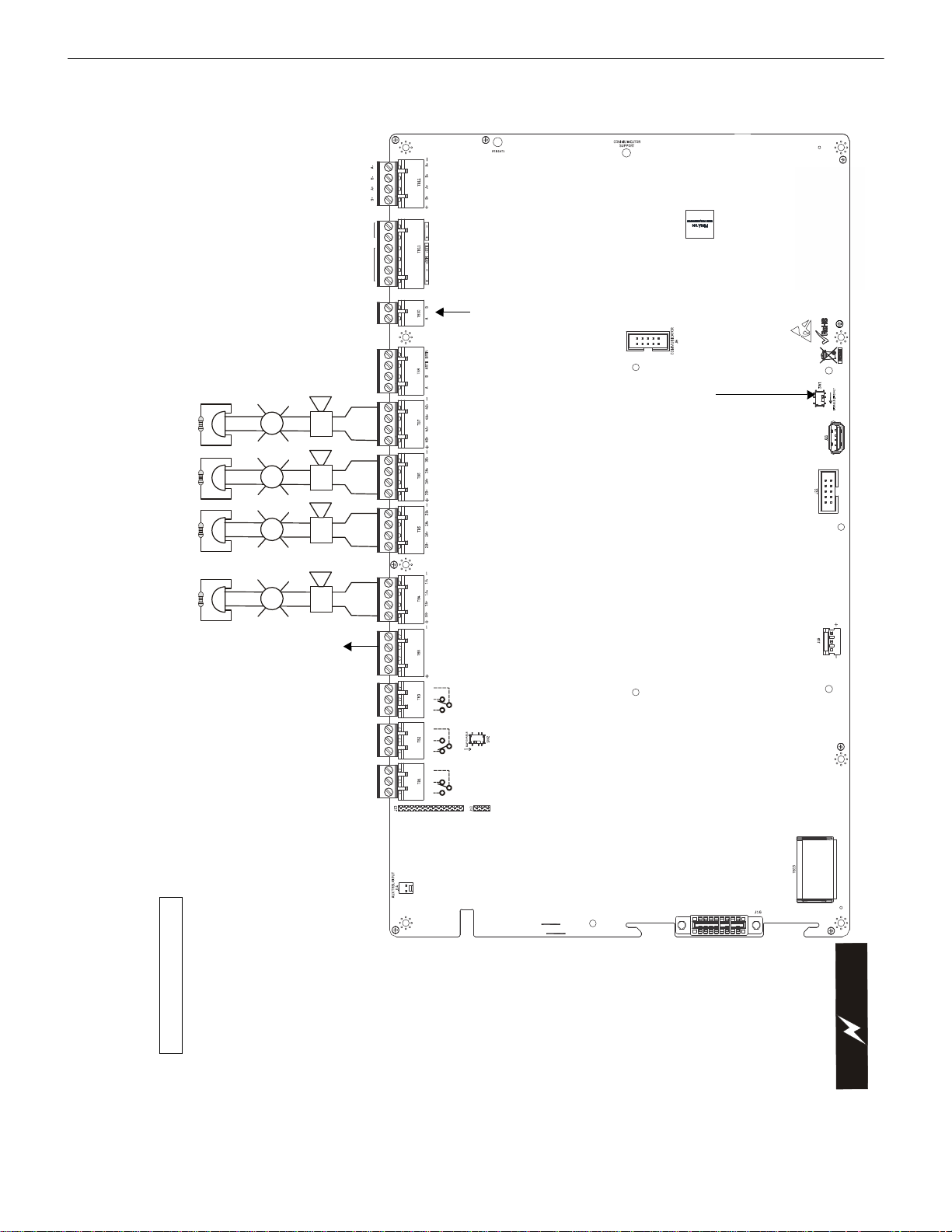
RTN- OUT-
250
V
COMMUNI
CATOR
DISPLAY
PW
R
2
24V
2
A
NPM
RTN+OUT+
BATT
ERY
N/L2EARTHH/L1
USB-A
CNO NC
CNONC
CNCNO
SUPV
TRBL
ALRM
ANN-L
C
E
S200-PCAREVES50-PCARE
V
SLC
PWR1
RMT SYNC ANN-BUS PRI
ANN-BUS SEC
NAC4NAC3
NAC2
NAC1
+
+
+
+
+
+
+
+
+
+
+
+
SLC Loop
(supervised)
Secondary
ANN-BUS
to Annunciators
(power-limited,
supervised)
Primary
ANN-BUS
to Annunciators
(power-limited,
Remote
Synchronization
Output
Supervised, Power-
Limited circuits
24 VDC filtered (0.35
amp maximum),
Requires a 4.7 Kohm
End-of-Line Resistor
Supervisory*Alarm*
Trouble
2 Programmable Relays &
Fixed Trouble Relay
Non-supervised relay contacts
Contact rating:
2.0 amps @ 30 VDC (resistive)
0.5 amps @ 30 VAC (resistive)
Contacts shown below in
normal condition (AC power
with no alarm, trouble, or
supervisory activity)
AC Fail Safe Trouble relay
switches to the NO position
during trouble conditions and
under loss of all power.
(*Factory default relay
programming)
NAC #1 NAC #2 NAC #4NAC #3
Notification Appliance Circuits
NAC #1, #2, #3, & #4 Class B or Class A
(Supervised, Power-Limited) (Special application) 2.5
amps max. per circuit
ELRs,
4.7K, 1/2W
(for Class
A wiring)
Auxiliary
Trouble
Input
C
A
U
T
I
O
N
!
H
I
G
H
V
O
L
T
A
G
E
AC Power
(Supervised,
Nonpower-Limited)
120 or 240 VAC, 50/60 Hz, 3.25 amps
Battery
24 VDC, supervised,
nonpower-limited,
18 AH maximum
USB Port J20
for firmware
updates, local
programming
using a
personal
computer and
FS-Tools
utility or a
thumb drive
To disable ground fault
detection, slide SW1 to the left.
Important! Disabling
Ground Fault Detection
voids UL/NFPA Class
identifications for circuits.
Disable Ground Fault only
with the approval of the
AHJ (Authority Having
Jurisdiction).
Special Application DC Power Outputs (24 VDC)
Nonsupervised, Power-Limited circuits
Nonresettable Power suitable for poweri ng
annunciators; Resettable Power suitable for
powering smoke detectors.
Aux Power 1: Resettable or Nonres ettable
Power, 24 VDC filtered, power-limited
(1.0 amp maximum). Class A or Class B
wiring possible. Supervision required for
Class B wiring. Supervise with a power
supervision relay EOLR-1
Aux Power 2: Nonresettable or Res ettable
Power, 24 VDC filtered, power-limited
(1.0 amp maximum). Supervision required.
Basic System Connections
Keypad
Connector
NPM Connector
Connection to the PWRMOD24
NAC power expander module
Connection to the IPOTS-
COM communicator card
for POTS and IP reporting
J12 & J13:
4XTMF
connection
SW2: 4XTMF
Supervisory Relay:
Slide switch to the
down position to
enable the relay
when the 4XTMF is
installed
ES-200X Series Manual — P/N LS10131-000FL-E:C 7/25/2018 11
Page 12
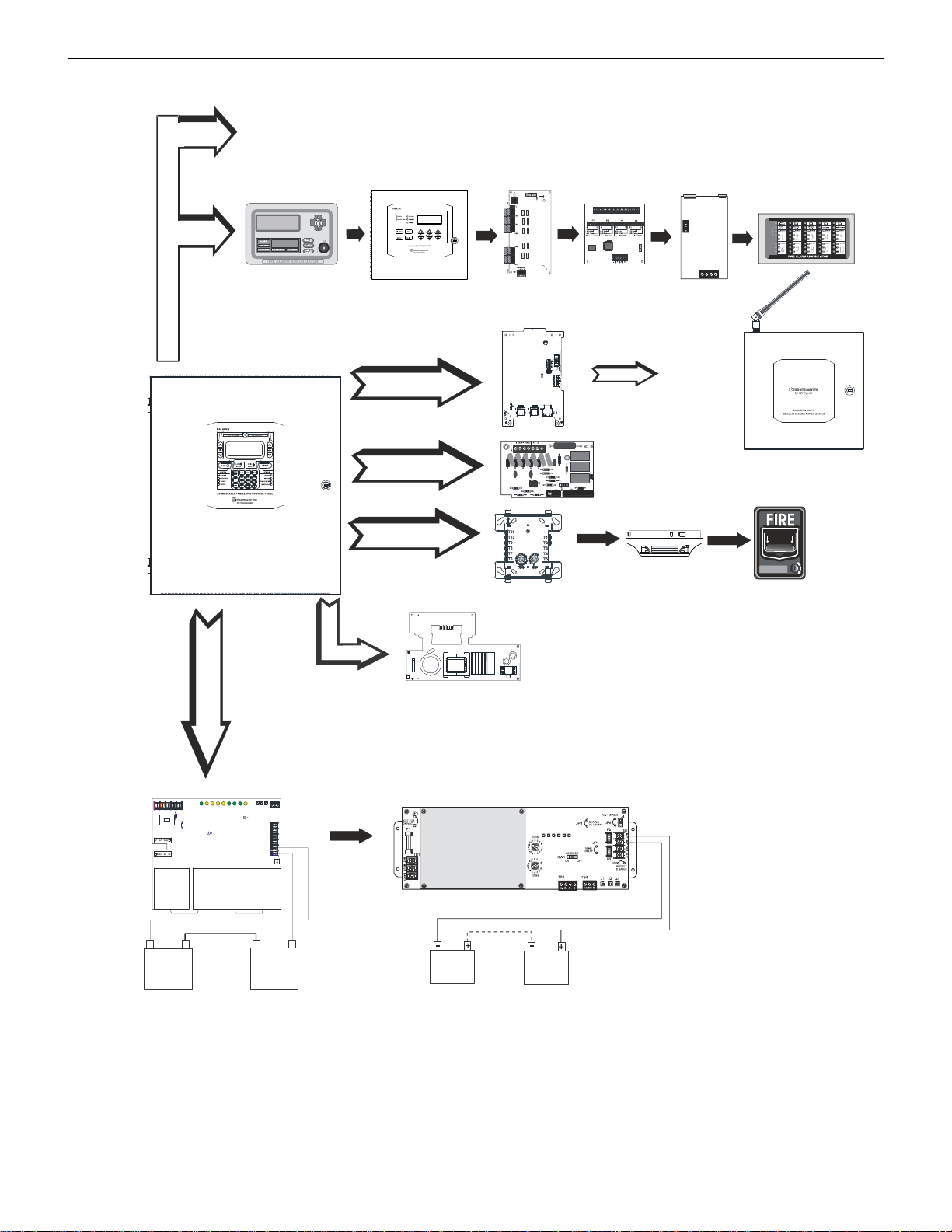
Peripheral Devices and Their Documents:
SW2SW
3
S
W
1
LED1LED2LED
3
L
E
D
4
L
E
D
5
L
E
D
6
L
E
D
7
L
E
D
8
J
3
J
5
J
4
ETH
L
I
N
E
2
L
I
N
E
1
Addressable Devices and SLC Wiring Doc. #51309
Wireless Gateway Doc. #LS10036-000FL-E
CHG-120F Charger
Doc. #50888
ANN-BUS - TB9/TB10
SLC Loop - TB12
Battery Connector - J15
es200annperi.wmf
ANN-80
LCD Text Annunciator
Doc. #52749
ANN-I/O
LED Driver
Doc. #151416
ANN-S/PG
Printer Driver
Doc. #151417
CHG-75 Charger
Doc. # 51315
ANN-(R)LED
LED Display
Doc. #53032
ANN-RLY
Relay Card
Doc. #53033
4XTMF
Reverse Polarity Module
J12 & J13
ANN Audio Control for ECC-50/100 Doc. #LS10001-000FL-E
IPOTS-COM
POTS and IP Communicator
Doc. #LS10184-000GE-E
J6
CELL-CAB-FL
GSM Communicator
Doc. #LS10186-000FL-E
PWRMOD24 NAC Power Expander
Doc. #LS10085-000GE-E
J16
J7
J15
ANN-100
LCD Text Annunciator
Doc. #LS10205-000FL-E
TB2
12 ES-200X Series Manual — P/N LS10131-000FL-E:C 7/25/2018
Page 13

The Fire-Lite ES-200X is an addressable FACP (Fire Alarm Control Panel) with a pre-installed communicato r ca rd th at is compact, cost
effective, intelligent, and has an extensive list of powerful features.The combination of Fire-Lite’s newer series devices and legacy 300
Series devices, along with the ES-200X FACP, offer the latest in fire protection technology. The power supply and all electronics are
housed in a metal cabinet, providing a complete fire control system for most applications. Optional modules, which plug into the main
circuit board, are available for special functions. Available accessories include multi-technology central station communicators, LED,
graphic, and LCD annunciators, reverse polarity/city box transmitter, local and remote upload/download software, and remote power
expansion.
The ES-200XC is a ULC-listed Canadian version of the FACP which offers the same features as the ES-200X, but is supplied standard
with a dress panel. Refer to “Canadian Option” on page 79 for a full description.
NOTE: Unless otherwise specified, the term ES-200X is used to refer to all versions of the panel.
Inventory
When ES-200X shipment is received, check that all parts have been included in shipment. The ES-200X shipment consists of one of
each of the following:
main circuit board with display
backbox with door
plastic bag containing screws, cables, ELRs, terminal blocks, etc.
1.1 Features and Options
• Pre-installed IPOTS-COM Ethernet IP and POTS (Plain Old Telephone Service) Central Station Communicator
• Optional CELL-MOD(C) or CELL-CAB-FL GSM Central Station Communicator over AlarmNet
• Automated activation of the ECC-50/100 Emergency Command Center
• ECC-FFT Firefighter Telephone option
• Compatible with SWIFT® wireless devices
• LiteSpeed™ polling protocol for faster SLC response time
• SLC operates up to 10,000 ft. (3,000 m) in LiteSpeed mode with twisted, unshielded wire (refer to “Wire Requirements” on
page 143)
• Single addressable SLC loop which meets NFPA Class A, Class B, and/or Class X requirements
• 198 addressable device capacity (99 detectors and 99 control/relay/monitor modules)
• 99 software zones
• Four (4) Class B or four (4) Class A NAC (Notification Appliance Circuits) circuits - special application power
• 3.0 amps total 24 VDC output circuit current in alarm condition
• NAC power expandable by 3.0 amps with optional PWRMOD24 module
• Four programmable function keys for ease of maintenance
• Two programmable relay outputs and one fixed trouble relay
• Synchronization output for remote power supply applications (special application)
• Built-in Programmer
• 80-character LCD display (backlit)
• Real-time clock/calendar with daylight savings time control
• History file with 1,000 event capacity
• Addressable sounder base compatibility
• Multi-criteria detector (smoke, heat, CO) with programmable response
• Advanced fire technology features:
Automatic drift compensation
Maintenance alert
Detector sensitivity test capability (NFPA 72 compliant)
Automatic device type-code verification
Point trouble identification
• Waterflow selection per module point
• Alarm verification selection per detector point
• Walktest, silent or audible
• PAS (Positive Alarm Sequence) and Pre-signal per point (NFPA 72 compliant)
• Silence inhibit timer option per NAC
• Autosilence timer option per NAC
• Continuous, March Time, Temporal or California code for main circuit board NACs with two-stage capability
• Selectable strobe synchronization per NAC
• Remote Acknowledge, Alarm Silence, Reset and Drill via addressable modules or ANN-80/ANN-100 Remote annunciator
• Auto-program (learn mode) reduces installation time. Reports two devices set to the same address
• Password and key-protected nonvolatile memory
• User programmable password
• Fully programmable from local keypad
Section 1: Product Description
ES-200X Series Manual — P/N LS10131-000FL-E:C 7/25/2018 13
Page 14

Product Description Specifications
• Optional FS-Tools programming utility for local or remote Upload/Download of programming and data (available for download
from www .firelite.com)
• Compatible with Fire-Lite’s devices in Lite Spe ed a nd CL IP mode (refer to SLC Wiring Manual for a list of compatible addressable
devices)
• Compatible with legacy Fire-Lite 300 Series devices in CLIP mode only (refer to the SLC Wiring Manual for a list of compatible
addressable devices)
• Optional 4XTMF module (conventional reverse polarity/city box transmitter)
• ANN-BUS for connection to following optional modules:
ANN-80 Remote Annunciator (UL applications only)
ANN-100 (FM and Canadian applications only)
ANN-I/O LED Driver
ANN-S/PG Printer Module
ANN-RLY Form-C Relay Module
ANN-LED Annunciator Module annunciates alarm, trouble and supervisory (required for Canada and emergency signaling)
ANN-RLED Annunciator Module annunciates alarms only
• Automated activation of the legacy ACC-25/50(ZS/T) Audio-Command-Center
1.2 Specifications
Refer to Illustration on page 10 for terminal locations and connections.
AC Power - TB13
Operates in either 120 or 240 VAC, 50/60 Hz, 3.25 amps, auto-sensing. No switch or jumper required.
Wire size: minimum 14 AWG (2.00 mm
Battery (Sealed Lead Acid Only) - J15
Maximum Charging Circuit: Normal Flat Charge – 27.6 VDC @ 1.5 amps
Maximum Battery Charger Capacity: 18 Amp Hour (FACP cabinet holds maximum of two 18 Amp Hour batteries. The BB-26 Battery
Box holds two 26 Amp Hour batteries and the CHG-75. For greater than 26 Amp Hour up to 120 Amp Hour batteries, use the CHG-75
or CHG-120F Battery Charger and BB-55F Battery Box).
Minimum Battery Size: 7 Amp Hour
Note: Refer to the programming section to disable the FACP battery charger when using an external battery charger.
Communication Loop - TB12
24 VDC nominal, 27.6 VDC maximum
Maximum length - refer to “Wire Requirements” on page 143)
Maximum loop current is 400 mA (short circuit) or 100 mA (normal)
Maximum loop resistance is 40 ohms
Supervised and power-limited circuit
Refer to SLC Wiring manual for wiring information
Notification Appliance Circuits - TB4, TB5, TB6, & TB7
Four (4) Class B NAC circuits or four (4) Class A circuits
Special Application, filtered power
Power-limited circuitry
NAC wiring requirements refer to “NAC Wiring” on page 144
Nominal operating voltage: 24 VDC
Current-limit: fuseless, electronic, power-limited circuitry
Maximum signaling current per circuit: 2.5 amps special application, 250 mA regulated (see Figure 1.1 on page 15)
End-of-Line Resistor: 4.7 kΩ, ½ watt (P/N 71252 UL listed) required for each circuit; system capable of 1.9 kΩ - 22 kΩ ELR range.
Refer to the Device Compatibility Document for listed compatible devices
Two Programmable Relays and One Fixed Trouble Relay - TB1, TB2, & TB3
Contact rating: 2.0 amps @ 30 VDC (resistive), 0.5 amps @ 30 VAC (resistive)
Form-C relays
Refer to Figure 2.6 on page 26 for information on power-limited relay circuit wiring
Nonresettable or Resettable Special Application Power (24 VDC Nominal) - TB11, Terminals 1 (+), 2 (-), 3(+), & 4(-)
(programmable)
Factory-set as nonresettable, suitable for powering annunciators
Programmable Class A or Class B wiring
Maximum ripple voltage: 20mV
Total DC current available is up to 1.0 amp (see Figure 1.1 on page 15)
Power-limited circuit
Note: Refer to the programming section to configure power as resettable/non-resettable and for Class A or Class B wiring.
RMS
2
) with 600 V insulation
14 ES-200X Series Manual — P/N LS10131-000FL-E:C 7/25/2018
Page 15
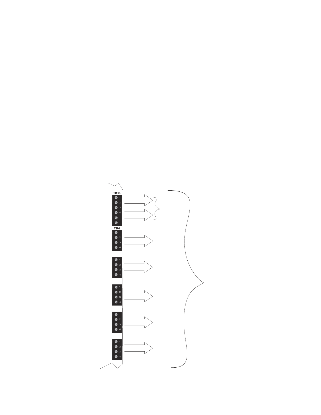
Specifications Product Description
TB5
TB6
TB7
TB8
5
6
Figure 1.1 Current Availability without PWRMOD24 Option
Refer to the battery calculations section for additional information.
Standby
2.0 amps max
per panel
Special Application
Nonresettable or
Resettable Power
Special Application
Resettable or
Nonresettable Power
NAC #1
NAC #2
NAC #3
NAC #4
1.0 amp max
per circuit
2.5 amps max
per circuit
Alarm
3.0 amps max*
per panel
Remote
Synchronization
Output
*Note: When the option module
PWRMOD24 is installed, an
additional 3.0 amps of alarm power is
available across NAC #1 through
NAC #4 and the remote
synchronization output expanding
max power to 6.0 amps
1.0 amp max
per circuit
2.5 amps max
per circuit
2.5 amps max
per circuit
2.5 amps max
per circuit
0.35 amp max
per circuit
Resettable or Nonresettable Special Application Power (24 VDC Nominal) - TB11, Terminals 5 (+) & 6 (-)
Factory-set as resettable, suitable for powering four-wire smoke detectors
Class B wiring only
Maximum ripple voltage: 20 mV
Total DC current available is up to 1.0 amp (see Figure 1.1)
RMS
Power-limited circuit
Refer to the Device Compatibility Document for listed compatible devices
Note: Refer to the programming section to configure power as resettable/non-resettable.
Remote Sync Output - TB8
Remote power supply synchronization output
24 VDC nominal special application power
Maximum current is 350 mA
End-of-Line Resistor: 4.7KΩ
Output linked to NAC 1 control
Supervised and power-limited circuit
Programmable Class A or Class B wiring
Secondary ANN-BUS - TB10
ANN-BUS annunciator connector, Terminal 1 (+/A) and Terminal 2 (-/B)
Annunciators require non-resettable power
Primary ANN-BUS - TB9
Class A or Class B wiring
ANN-BUS annunciator connector, Terminal 1 (+/A) and Terminal 2 (-/B)
Class A wiring uses Terminal 3 (+/A Return) and Terminal 4 (-/B Return)
Annunciators require non-resettable power
The following figure illustrates the maximum current that is possible for each major panel output circuit and the total current available
from the FACP.
ES-200X Series Manual — P/N LS10131-000FL-E:C 7/25/2018 15
Page 16
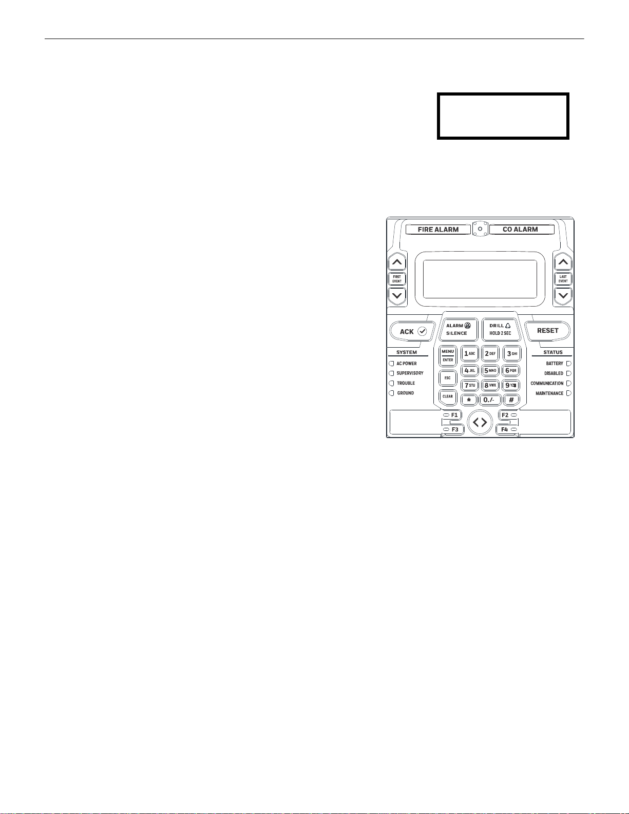
Product Description Controls and Indicators
SYSTEM NORMAL
10:00A 010118
@
Figure 1.2 Membrane/Display Panel
es200kypd.wmf
1.3 Controls and Indicators
LCD Display
The F AC P uses an 80-character
(4 lines X 20 characters) high viewing angle LCD display. The display includes a long life
LED backlight that remains illuminated. If AC power is lost and the system is not in alarm,
the LED backlight will turn off to conserve batteries.
Key Panel
Mounted on the main circuit board, the key panel includes a window for the LCD display
and LED indicators as listed below. The key panel, which is visible with the cabinet door closed, has 30 keys, including a 16 key alphanumeric pad similar to a telephone keypad.
LED Indicators
LED indicators are provided to annunciate the following conditions:
• Fire Alarm (red)
• CO Alarm (red)
• AC Power (green)
• Supervisory (yellow)
• Trouble (yellow)
• Ground fault (yellow)
• Battery fault (yellow)
• Disabled (yellow)
• Maintenance (yellow)
• Communication (yellow)
• Alarm Silenced (yellow)
• F1-F4 Function Keys (yellow)
Function keys:
• Acknowledge
• Alarm Silence
•Drill
• Reset (lamp test)
• four (4) programmable function keys
Service/program keys:
• Keys labeled 1 to 9
•* key
•# key
• 0 (recall) key
• First Event and scroll keys
• Last Event and scroll keys
•Clear key
•Escape key
• Two cursor keys (left and right)
• Menu/Enter key
Local Piezo Sounder
A piezo sounder provides separate and distinct pulse rates for alarm, trouble and supervisory conditions.
1.4 Components
Main Circuit Board
The main circuit board contains the system’s CPU, power supply, other primary components and wiring interface connectors. The
4XTMF option module plugs in and is mounted to the main circuit board.
IPOTS-COM Communicator Card
The pre-installed IP/POTS communica tor card transmits system status (alarms, troubles, AC loss, etc.) to a Central Station via the pub lic
switched telephone network. It also allows remote programming or interrogation of the control panel using the FS-Tools Upload/Download utility and a hard-wired Ethernet IP connection. Any personal computer with Windows
software may serve as a Service Terminal. This allows download of the entire program or upload of the entire program, history file,
walktest data, current status and system voltages. Refer to Section 6 on page 123 for more information.
The IPOTS-COM digital communicator provides the following POTS functions:
• Line Seizure: takes control of the phone lines disconnecting any premises phones
• Off/On Hook: performs on and off-hook status to the phone lines
• Listen for dial tone: 440 Hz tone typical in most networks
16 ES-200X Series Manual — P/N LS10131-000FL-E:C 7/25/2018
®
7 or greater, 32 or 64 bit, and FS-Tools
Page 17

Optional Modules Product Description
Battery Cable P/N 75287
• Dialing the Central Station(s) number: default is Touch-Tone®, programmable to rotary
• For tone burst or touchtone type formats: discern proper Ack and Kissoff tone(s). The frequency and time duration of the tone(s)
varies with the transmission format. The control panel will adjust accordingly.
• Communicate in the following formats:
Ademco Contact ID
SIA DCS 8
SIA DCS 20
Cabinet
The ES-200X backbox provides space for two batteries (up to 18 Amp Hour). Ample knockouts are provided for system wiring. Also
available is an optional dress panel (DP-ES-R), which mounts to the inside of the cabinet (required by ULC for Canadian installations).
Batteries
The ES-200X cabinet provides space for two batteries (up to 18 Amp Hour). Batteries larger
than 18 Amp Hour require an external charger such as the CHG-75 or CHG-120F and a UL
listed battery box such as the BB-26 or BB-55F. Batteries must be ordered separately.
1.4.1 Intelligent Addressable Detectors
Intelligent, addressable detectors provide information to the control panel on an SLC Signaling Line Circuit (refer to the SLC Wiring
Manual for detailed information on device installation, wiring and operation). This allows the control panel to continually process the
information to determine the status (alarm, trouble, maintenance or normal) of each detector. Each detector responds to an SLC address
that is set in the detector head using built-in rotary decimal switches. The maximum address cannot exceed address 99. Note that a blinking LED on an intelligent detector indicates communication between the detector and the control panel.
These devices (350 Series or newer) can operate in CLIP mode (Classic Loop Interface Protocol) or LiteSpeed mode to provide a
quicker response. They are also compatible with older 300 Series devices. If a mix of old and new series devices are installed on the
same loop, the F A CP must be programmed to operate in CLIP mode. Refer to the SLC Wiring Manual for a list of compatible addressable detectors.
1.4.2 Intelligent Addressable Modules
Control Modules and Monitor Modules provide an interface between the control panel and conventional notification and initiating
devices. Each module can be set to respond to an address with built-in rotary switches. The maximum address cannot exceed address 99.
Note that a blinking LED on an addressable module indicates communication between the module and the control panel.
These devices (i.e., MMF-300, MDF-300, MMF-301, MMF-302, CMF-300, CRF-300) can operate in CLIP mode (Classic Loop Interface Protocol) or LiteSpeed mode to provide a quicker response. They are also compatible with older 300 series devices. If a mix of old
and new series devices are installed on the same loop, the FACP must be programmed to operate in CLIP mode. Refer to the SLC W iring
Manual for a list of compatible addressable modules. Refer to the Device Compatibility Document for a list of approved conventional
notification and initiating devices.
1.4.3 Addressable Device Accessories
End-of-Line Resistor Assembly
The End-of-Line resistors are included with each module. Refer to the specific module documentation for specific information.
Power Supervision Relay
The UL listed End-of-Line power supervision relay is us ed to supervise the p ower to 4-wire smo ke detectors and notification appliances.
EOL-C(R/W) Mounting Plate
The EOL-CR (red) and EOL-CW (white) are single End-of-Line resistor plates which are required for use in Canada. An ELR, which is
supplied with each module and fire alarm control panel, is mounted to the EOL-C(R/W) plate. Resistors mounted to the plate can be used
for the supervision of a monitor and control module circuit.
1.5 Optional Modules
The ES-200X main circuit board includes option module connectors for the following modules:
CELL-MOD(C)/CELL-CAB-FL(C)
Optional GSM communicator card for central station reporting. It mounts in its own plastic or metal enclosure. Use of the CELLMOD(C)/CELL-CAB-FL(C) requires the IPOTS-COM communicator. Connections are made from the CELL-MOD/CELL-CAB to the
IPOTS-COM.
PWRMOD24 Power Expander Module
Optional power module. Increases NAC power output by 3 amps.
ES-200X Series Manual — P/N LS10131-000FL-E:C 7/25/2018 17
Page 18

Product Description Accessories
4XTMF Transmitter Module
The 4XTMF provides a supervised output for local energy municipal box transmitter, alarm and trouble reverse polarity. It includes a
disable switch and disable trouble LED. A jumper on the module is used to select an option which allows the reverse polarity circuit to
open with a system trouble condition if no alarm condition exists. The module plugs into connectors J5 and J6 which are located near the
right edge the main circuit board. When the 4XTMF module is installed, Jumper JP3, on the main circu it board, must be cut to allow
supervision of the module.
1.6 Accessories
1.6.1 FS-Tools Programming Utility
The FS-Tools Programming Utility can be used to locally or remotely program the FACP from most Windows® compatible computers
(PC), running Windows 7 or newer, 32 or 64 bit. The FACP program files can also be created and stored on the PC for future download
to the control panel. FS-Tools can be downloaded from www.firelite.com. A standard USB cable with male-A to male-A connectors,
which must be purchased separately, is required for local connection of the PC to the USB port J20 on the FACP main circuit board.
Remote programming requires that the PC have a GSM or Ethernet connection.
FS-Tools also provides the ability to create panel program files on a USB flash drive. The drive can then be plugged into USB port J20
on the FACP main circuit board.
Important: Remote modification of FACP programming requires that the panel be enabled for remote download (refer to “FS-Tools
Upload/Download” on page 123). Remote interrogation of panel programming, history logs, detector status, etc., is possible without
enabling the remote download option.
1.6.2 Dress Panel
An optional dress panel DP-ES-Ris available for the ES-200X (required by ULC for Canadian installations). The dress panel restricts
access to the system wiring while allowing access to the key panel. A ground strap must be connected between the stud on the inside of
the dress panel and the ground stud in the backbox.The dress panel mounts to the backbox with two (2) #6-32 screws. The ES-200XC is
supplied standard with a dress panel.
1.6.3 Trim Ring
An optional Trim Ring (P/N TR-CE) is ava ilable for the FACP backbox. The Trim Ring adds 1.5” of wall coverage around the backbox,
concealing hardware and providing a finished appearance for a semi-flush mounted panel.
1.6.4 Battery Box
BB-26
The BB-26 battery box may be used to house up to two 26 AH batteries and the CHG-75 Battery Charger.
BB-55F
The BB-55F battery box may be used to house two 26 AH batteries, two 60 AH batteries or one 100 AH battery . When the CHG-120F is
mounted in the BB-55F, two 26 AH or one 60 AH battery may also be housed in the battery box.
1.6.5 Battery Charger
CHG-75 Battery Charger
The CHG-75 is capable of charging up to 75 AH lead-acid batteries with the ES-200X FACP. The FACP battery charger must be disabled, by removing jumper JP5, when using the CHG-75. The charger and up to 26 AH batteries can be housed in the BB-26 battery box.
Larger batteries and the charger can be housed in the BB-55F battery box which can be mounted up to 20 feet away from the control
panel. Refer to the CHG-75 Manual for additional information.
18 ES-200X Series Manual — P/N LS10131-000FL-E:C 7/25/2018
Page 19

Accessories Product Description
!
CHG-120F Battery Charger
The CHG-120F is capable of charging up to 120 AH lead-acid batteries with the ES-200X FACP. The FACP battery charger must be disabled, by removing jumper JP5, when using the CHG-120F . The batteries and charger can be housed in the BB-55F battery box which
can be mounted up to 20 feet away from the control panel. Note that when using the BB-55F for housing the char ger and batteries greater
than 26AH, multiple BB-55Fs are required. Refer to the CHG-120F Manual for additional information.
1.6.6 ECC-50/100
The ECC-50/100 is a single channel, 50 watt, 25 V
notification applications, or both. Automatic activation of the ECC-50/100 is possible via eight Command Input Circuits (CMD) or via
the ANN BUS serial communications link from the ES-200X FACP.
, emergency voice evacuation panel that may be used for fire applications, mass
RMS
1.6.7 ECC-FFT
An ECC-FFT Fire Fighter Telephone provides supervision, annunciation, and control for local and remote telephone handsets. The ECCFFT’s keypad provides indications of phone activation and corresponding trouble conditions. Not for use in Canadian applications.
1.6.8 W-GATE Wireless Gateway
The W - GATE Wireless Gateway acts as a bridge between a group of wireless fire devices and a LiteSpeed SLC loop on the ES-200X. It
is powered by the SLC loop or by a regulated, external 24VDC UL-listed power supply evaluated for life safety. A vailable wireless
devices include a photo detector, a photo/heat detector, a fixed-temperature heat detector, a rate-of-rise heat detector, a monitor module,
and a relay module. A maximum of 100 wireless devices can be used in the system. For details about wireless devices, system setup, and
operation, see the SWIFT® Smart Wireless Integrated Fire Technolog y Instruction Manual #LS10036-000FL-E.
NOTE: The W-GATE, as part of the wireless network, has been tested for compliance with the Federal Communications Commission
(FCC) requirements of the United States Government. It has not been evaluated for use outside the USA. Use of this system outside the
USA is subject to local laws and rules to which this product may not conform. It is the sole responsibility of the user to determine if this
product may be legally used outside the USA.
1.6.9 ANN-BUS Annunciators/Modules
WARNING: RISK OF ELECTRICAL SHOCK AND EQUIPMENT DAMAGE
DISCONNECT ALL SOURCES OF POWER (AC AND DC) BEFORE INSTALLING OR REMOVING ANY MODULES OR
WIRING.
Guidelines
• A variety of optional annunciation devices can be connected to an ANN-BUS communication circuit. ANN Series devices can be
connected to the primary communication circuit (EIA-485) terminals on TB9. A secondary communication circuit for these devices
is available at TB8. Each ANN-BUS communication circuit supports up to eight (8) annunciators. Compatible devices include the
following:
– ANN-80 LCD Annunciator (UL applications only)
– ANN-100 LCD Annunciator (FM and Canadian applications only)
– ANN-S/PG Serial/Parallel Printer Interface Module
– ANN-I/O LED Driver Module
– ANN-LED Annunciator Module (alarm, trouble, supervisory LEDs)
– ANN-RLED Annunciator Module (red alarm LEDs only)
– ANN-RLY Relay Module (can be mounted in the supplied FACP chassis)
• When operating two ANN-BUS circuits, only one ANN-S/PG Printer module can be used in the system.
• The panel is capable of operating a primary ANN-BUS (TB9) and a secondary ANN-BUS (TB10) simultaneously.
• Only one audio system (ECC-50/100 or ACC-25/50) may be connected to the ANN-BUS.
ANN-80/ANN-100 Remote Fire Annunciators
The ANN-80 and ANN-100 Annunciators are 80 charac ter, backlit LCD remote fire annunciators. They mimic the display on the control
panel and will annunciate device type, point alarm, trouble or supervisory conditions, zone assignments plus any custom alpha labels
programmed into the FACP. The annunciators also provide system status LEDs to display AC Power, Alarm, Trouble, Supervisory and
Alarm Silenced conditions. Additionally, the annunciators are capable of remotely performing critical system functions such as
Acknowledge, Silence, Reset and Drill. Communication between the annunciators and the FACP is accomplished over a two wire RS485 serial interface employing the ANN-BUS co mmunication format. The devices are powered, v ia two additio nal wires, from either the
host F A CP or remote UL-listed, filtered, regulated, power supply.
The function buttons and piezo sounder may be individually enabled and disabled through the FACP software. Refer to “ANN-80/100
Options” on page 98 for a description of this feature and programming information.
ANN-S/PG Serial/Parallel Interface Module
The ANN-S/PG Serial/Parallel Interface module allows the connection of a remote serial or parallel printer to the FACP for a real-time
log of system events, detector status reports and event history. The module is provided with a plastic enclosure for surface mounting.
ES-200X Series Manual — P/N LS10131-000FL-E:C 7/25/2018 19
Page 20

Product Description Getting Started
ANN-I/O LED Driver Module
The ANN-I/O is an LED driver module that can be used in a wide variety of applications, including as an interface with mos t customized
graphic annunciators. The ANN-I/O can drive up to 40 LEDs. The module is provided with a plastic wall mount.
ANN-LED Annunciator Module
The ANN-LED and ANN-RLED annunciator modules provide LED annunciation of general system faults and input zones/points when
used with a compatible F ACP. The ANN-LED module provides alarm (red), trouble (yellow) and supervisory (yellow) indication for up
to ten input zones or addressable points. The ANN-RLED provides alarm (red) indication for up to 30 input zones or addressable points.
Multiple ANN-(R)LED modules may be used for full system coverage.
ANN-RLY Annunciator Module
The ANN-RLY relay module provides 10 programmable Form-C relays when used with a compatible FACP.
1.7 Getting Started
The following is a brief summary of the minimal steps involved in bringing an ES-200 on-line:
• Install backbox and main circuit board (refer to “Mounting the Backbox” on page 22)
• Address and install intelligent devices (refer to the SLC Wiring Manual)
• Enter autoprogramming (refer to “Autoprogram” on page 52)
• Resolve programming conflicts
• Go to point program to enter specific data (refer to “Point Program” on page 53). Use the right and left arrow keys to navigate
between devices.
1.8 Telephone Requirements and Warnings
1.8.1 Telephone Circuitry
Ringer Equivalence Number (REN) = 0.3A
AC Impedance: 10.0 Mega Ohm
Complies with FCC Part 68
Mates with RJ31X Male Connector
Supervision Threshold: loss of phone line voltage for 2 minutes
The REN is used to determine the quantity of devices which may be connected to the telephone line. Excessive RENs on the telephone
line may result in the devices not ringing in response to an incoming call. In most, but not all areas, the sum of the RENs should not
exceed five (5.0). To be certain of the number of devices that may be connected to the line as determined by the total RENs, contact the
telephone company to determine the maximum REN for the calling area.
Before connecting the control panel to the public switched telephone network, the installation of two RJ31X jacks is necessary . If tr ouble
is experienced with this equipment, for repair or warranty information, please contact:
Manufacturer: Honeywell International, Inc.
One Fire-Lite Place
Northford, CT 06472
(203) 484-7161
Product Model Number: ES-200X
FCC Registration Number: US:1W6AL03AEVOLX
Ringer Equivalence: 0.3A
NOTE: This equipment complies with Part 68 of the FCC rules and the requirements adopted by the ACTA. On the inside of the FACP
door is a label that contains, among other information, a product identifier in the format US:AAAEQ##TXXXX. If requested, this number
must be provided to the telephone company.
Alarm dialing equipment must be able to seize the telephone line and place a call in an emergency situation. It must be able to do this
even if other equipment (telephone, answering system, computer modem, etc.) already has the telephone line in use. To do so, alarm dialing equipment must be connected to a properly installed RJ31X jack that is electrically in series with and ahead of all other equipment
attached to the same telephone line. If there are any questions concerning these instructions, consult the telephone company or a qualified installer about installing the RJ31X jack and alarm dialing equipment. Refer to “IPOTS-COM Communicator” on page 30 for an
illustration of the proper installation of this equipment.
Important! The DACT must not be used to dial a phone number that is call-forwarded.
20 ES-200X Series Manual — P/N LS10131-000FL-E:C 7/25/2018
Page 21

Telephone Requirements and Warnings Product Description
1.8.2 Telephone Company Rights and Warnings
The telephone company, under certain circumstances, may temporarily discontinue services and/or make changes in its facilities, services, equipment or procedures which may affect the operation of this control panel. However, the telephone company is re quired to give
advance notice of such changes or interruptions.
If the control panel causes harm to the telephone network, the telephone company reserves the right to temporarily discontinue service.
Advance notification will be provided except in cases when advance notice is not practical. In such cases, notification will be provided
as soon as possible. The opportunity will be given to correct any problems and to file a complaint with the FCC if you believe it is necessary.
DO NOT CONNECT THIS PRODUCT TO COIN TELEPHONE, GROUND START, OR PARTY LINE SERVICES.
When the control panel activates, premise phones will be disconnected.
T wo separate phone lines are required. Do not connect both telephone interfaces to the same telephone line.
The control panel must be connected to the public switched telephone netw ork upstream (as first device) of any private telephone system
at the protected premises.
A plug and jack used to connect this equipment to the pr emises wiring and telephone ne twork must comp ly with the applicable FCC Part
68 rules and requirements adopted by ACTA. This equipment is designed to be connected to the telephone network or premises wiring
using a compliant RJ31X male modular plug and compatible modular jack that is also compliant.
1.8.3 For Canadian Applications
The following is excerpted from CP-01 Issue 5:
NOTICE: The Industry Canada (IC) label identifies certified equipment. This certification means that the equipment meets certain tele-
communications network protective, operational and safety requirements as prescribed in the appropriate Terminal Equipment Technical
Requirements document(s). The Department does not guarantee the equipment will operate to the users’ satisfaction.
Before installing this equipment, users should ensure that it is permissible to be connected to the facilities of the local telecommunications company. The equipment must also be installed using an acceptable method of connection. The customer should be aware that
compliance with the above conditions may not prevent degradation of service in some situations.
Repairs to certified equipment should be made by an authorized Canadian maintenance facility designated by the supplier . Any repairs or
alterations made by the user to this equipment, or equipment malfunctions, may give the telecommunications company cause to request
the user to disconnect the equipment.
Users should ensure, for their own protection, that the electrical ground connections of the power utility, telephone lines and internal
metallic water pipe system, if present, are connected together. This precaution may be particularly important in rural areas.
CAUTION
Users should not attempt to make such connections themselves, but should contact the appropria te electri c inspections author ity, or elec-
trician.
“The Ringer Equivalence Number
allowed to be connected to a telephone interface. the termination of an interface may consist of any combination of devices subject only
to the requirement that the sum of the REN of all devices does not exceed 5.”
DOC Compliance - “This digital apparatus does not exceed the Class A limits for radio noise emissions from digital apparatus set out in
the Radio Interference Regulations of the Canadian Department of Communications.”
Representative: NOTIFIER/FIRE•LITE, CANADA
(REN) assigned to each terminal device provides an indication of the maximum number of terminals
10 Whitmore Road
Woodbridge, Ontario L4L 7Z4
Phone: (905) 856-8733
F AX: (905) 856-9687
IC Certificate Number: 2132A-EVOLX
Ringer Equivalence Number (REN): 0.3A
Load Number: 2
ES-200X Series Manual — P/N LS10131-000FL-E:C 7/25/2018 21
Page 22
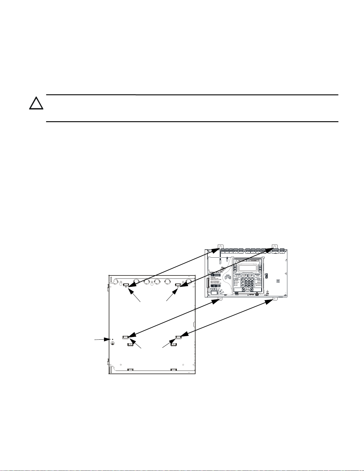
The cabinet may be either semi-flush or surface mounted. The cabinet mounts using two key slots and two 0.250” (6.35 mm) diameter
!
RTN-OUT-
COMMUNICATOR
DISPLAY
24V
RTN+OUT+
BATTERY
N/L2EARTHH/L1
USB-A
C
NO NC
CNO NC
CNCNO
SUPVTRBLALRM
ANN-LC
SLC
RMT SYNC
ANN-BUS PRI
ANN-BUS SEC
NAC4NAC3
NAC2
NAC1
@
Figure 2.1 ES-200X Chassis Removal and Installation
Backbox
Main Circuit Board on chassis
mounting studs
es200chassisinbox.wmf
grounding stud
mounting slots
holes located in the backbox. The key slots are located at the top of the backbox and the two securing holes at the bottom.
Carefully unpack the system and check for shipping damage. Mount the cabinet in a clean, dry, vibration-free area where extreme tem-
peratures are not encountered. The area should be readily accessible wit h sufficient room to easily install and maintain the panel. Locate
the top of the cabinet approximately 5 feet (1.5 m) above the floor with the hinge mounting on the left. Determine the number of conductors required for the devices to be installed. Sufficient knockouts are provided for wiring convenience. Select the appropriate knockout(s)
and pull the conductors into the box. All wiring should be in accordance with the National and/or Local codes for fire alarm systems.
2.1 Mounting the Backbox
CAUTION: STATIC SENSITIVE COMPONENTS
THE CIRCUIT BOARD CONTAINS STATIC-SENSITIVE COMPONENTS. ALWAYS GROUND YOURSELF WITH A
PROPER WRIST STRAP BEFORE HANDLING ANY BOARDS SO THAT STATIC CHARGES ARE REMOVED FROM THE
BODY. USE STATIC SUPPRESSIVE PACKAGING TO PROTECT ELECTRONIC ASSEMBLIES.
To prevent damage to the circuit board and to facilitate backbox mounting, the chassis with main circuit board can be easily removed.
Loosen the two 3/8” nuts securing the top flanges of the chassis, then slide the chassis up to free it from the lower tabs. Pla ce the chassis
assembly in a safe location until it can be reinstalled in the backbox.
1. Mark and pre-drill hole in the wall for the center top keyhole mounting bolt using the dimensions illustrated in Figure 2.2 on
page 23.
2. Install center top fastener in the wall with the screw head protruding.
3. Place backbox over the top screw, level and secure.
4. Mark and drill the left and right upper and lower mounting holes.
Note: Outer holes (closest to sidewall) are used for 16” O.C. stud mounting.
5. Install remaining fasteners and tighten.
6. When the location is dry and free of construction dust, install the chassis/circuit board assembly.
7. Mount the chassis to the backbox by aligning the two mounting tabs with the slots in the backbox, then position the two mounting
hole tabs over the studs with nuts located in the upper portion of the backbox.
8. Slide the tabs located on the bottom of the chassis into the mounting slots in the backbox by pressing the chassis down.
9. Secure the chassis to the backbox by tightening the two mounting nuts (#10-32) at the top, and to ensure proper grounding, use a
3/8” nut driver or socket.
10. If the main circuit board is not already attached to the chassis, install it by positioning the ten mounting holes over the studs on the
chassis and secure with the supplied screws.
Section 2: Installation
22 ES-200X Series Manual — P/N LS10131-000FL-E:C 7/25/2018
Page 23
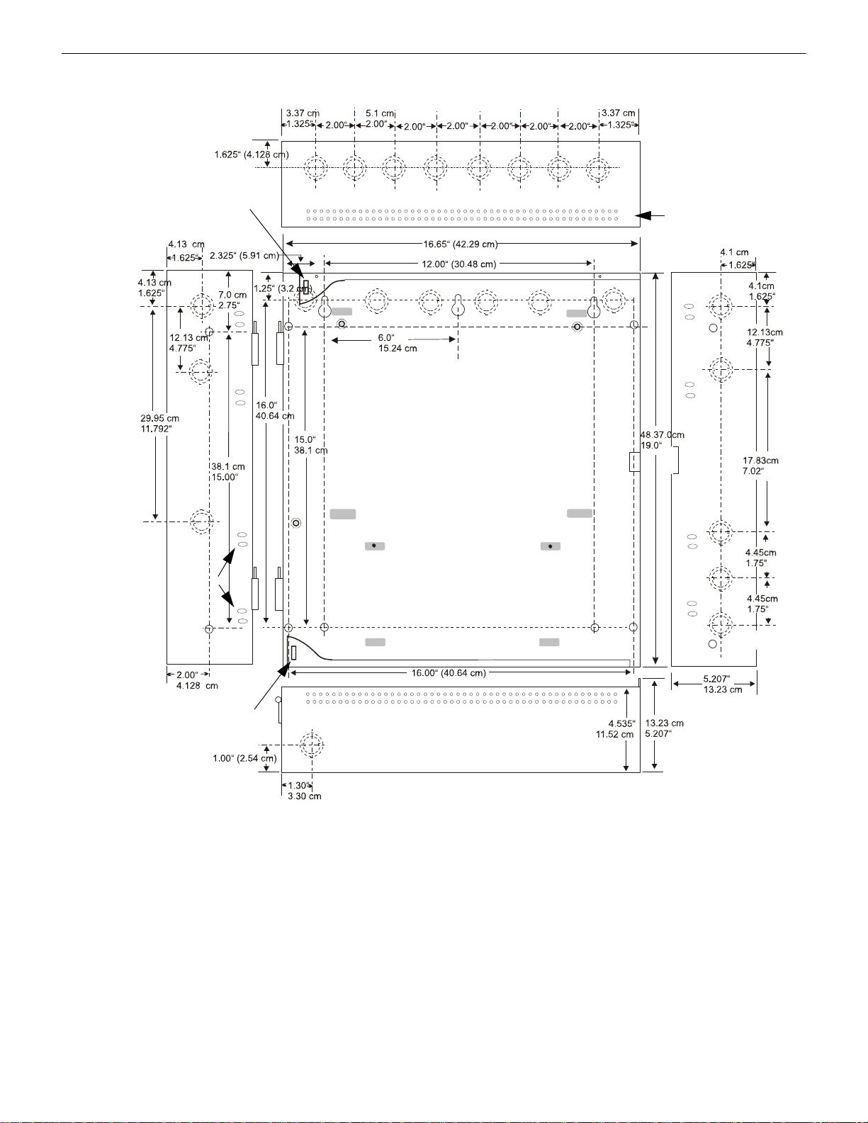
Mounting the Backbox Installation
Figure 2.2 ES-200X Cabinet Mounting
9050udencl.wmf
Semi-Flush
Mounting
Do not recess box more
than 3.875” into wall to
avoid covering venting
holes on top of box.
Hinge Slot for optional
Dress Panel
Hinge Slot for optional
Dress Panel
Semi-flush
mounting hole
Mounting
slots for
optional
Trim Ring
ES-200X Series Manual — P/N LS10131-000FL-E:C 7/25/2018 23
Page 24
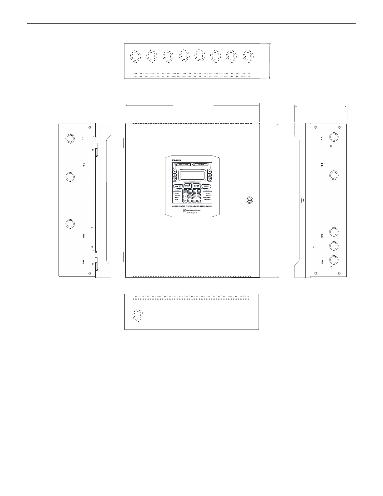
Installation Mounting the Backbox
6.537” (16.6cm)
5.207” (13.23cm)
16.822” (42.73 cm)
19.26” (48.92 cm)
Figure 2.3 Cabinet Dimensions
Height
Depth
Width
Left Side
Right Side
Top
Bottom
An optional Trim Ring (P/N TR-CE-) is also available for semi-flush mount installations.
24 ES-200X Series Manual — P/N LS10131-000FL-E:C 7/25/2018
Page 25
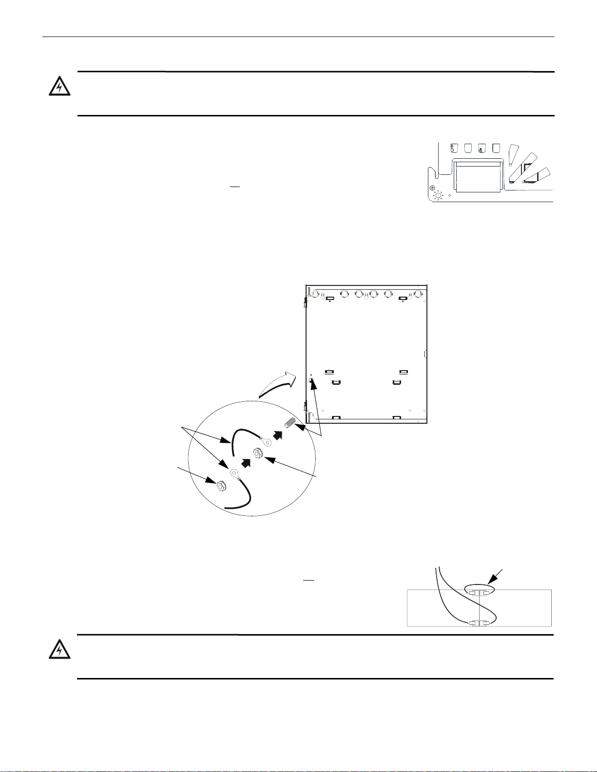
Power Installation
!
N/L2EARTHH/L1
Figure 2.4 Earth Ground Connection
9
2
0
0
g
r
n
d
.
w
m
f
grounding stud
keps nut
keps nut
Grounding
Cable #71073
-
-
+
+
Interconnect
Cable
!
2.2 Power
WARNING: RISK OF EQUIPMENT DAMAGE AND PERSONAL INJURY
SEVERAL DIFFERENT SOURCES OF POWER CAN BE CONNECTED T O THIS PANEL. DISCONNECT ALL SOURCES
OF POWER BEFORE SERVICING. THE PANEL AND ASSOCIATED EQUIPMENT MAY BE DAMAGED BY REMOVING
AND/OR INSERTING CARDS, MODULES OR INTERCONNECTING CABLES WHILE THIS UNIT IS ENERGIZED.
2.2.1 AC Power and Earth Ground Connection
Primary power required for the FACP is 120 or 240 VAC, 50/60 Hz, 3.25 amps. The FACP will
auto-detect the voltage used. No special switch or jumper is required to select AC power . Overcurrent protection for this circuit must comply with Article 760 of the National Electrical Code (NEC)
and/or local codes. Use 14 AWG (2.00 mm
certain that the AC mains circuit breaker is off
and the control panel. Connect wiring from the AC mains to TB13 on the FACP, being careful to
observe proper connections.
Remove the two keps nuts from the grounding stud in the backbox. Connect the incoming earth ground wire to supplied cable #71073
with a wire nut. Position the ring terminal end over the grounding stud. Secure with one of the keps nuts. Place the ring terminal from the
other supplied ground cable #71073 over the ground stud and secure with the second keps nut. Wire the ground cable to the bottom position of TB11. Refer to Figure2.1 on page22 for location of the stud. Ensure that the ground for AC mains is the first cable installed,
closest to the backbox. This connection is vital in reducing the panel’s susceptibility to transients generated by lightning an d electrostatic
discharge. Apply AC power to the panel only after the system is completely installed and visually checked. Note that AC power must be
applied to the panel before installing the battery interconnect cable (refer to the foll owing sec t ion).
2
) or larger wire with 600 volt insulation rating. Make
before wiring any connections between the mains
2.2.2 Battery Power
ES-200X Series Manual — P/N LS10131-000FL-E:C 7/25/2018 25
The batteries must be sealed lead acid type. Before connecting the batteries to the FACP,
make certain that the interconnect cable between the batteries is not
connected. Do not connect the interconnect cable until the system is completely installed. Observe polarity when
connecting the batteries. Connect the battery cable to J9 on the main circuit board. Refer to
“Power Supply Calculations” on page 128, for calculation of the correct battery rating.
WARNING: RISK OF PERSONAL INJURY
BATTERY CONTAINS SULFURIC ACID WHICH CAN CAUSE SEVERE BURNS TO THE SKIN AND EYES AND CAN
DESTROY FABRICS. IF CONTACT IS MADE WITH SULFURIC ACID, IMMEDIATELY FLUSH THE SKIN OR EYES WITH
WATER FOR 15 MINUTES AND SEEK IMMEDIATE MEDICAL ATTENTION.
Page 26

Installation Relays
+ -
+ - + -
PWR2
24V
PWR1
Figure 2.5 Special Application Power Outputs - 24 VDC
Power-limited Non-resettable or Resettable Power
1.0 amperes max., 24 VDC nominal filtered, nonresettable or resettable power is programmable. PWR1
can be programmed as Class B or Class A.
Power-limited Resettable or Non-resettable Power
1.0 amperes max., 24 VDC nominal filtered, programmable
resettable or non-resettable power can be drawn from TB11
Terminals 5(+) and 6(-)
e
s
2
0
0
t
b
1
1
.
w
m
f
TB11
Optional Class A
wiring return
CNO NC
C
NONC
CNCNO
SUPV
TRBL
ALRM
Figure 2.6 Relay Terminals
Relay contacts shown with power
applied to panel and no active
troubles, alarms or supervisories
TB1
Note that the programmable relay
labeled as Relay 1 is factory default
programmed as Alarm and
programmable Relay 3 is factory default
programmed as Supervisory.
The relay labeled Relay 2 is fixed as a
Trouble relay and cannot be changed. It
is a fail-safe relay which will transfer on
any trouble or total power failure.
e
s
2
0
0
r
l
y
.
w
m
f
TB2 TB3
RELAY 1
RELAY 2 RELAY 3
2.2.3 Special Application DC Power Output Connection
All Special Application DC power outputs are power-limited (refer to “UL Power-limited Wiring Requirements” on page 29).
2.3 Relays
The F AC P provides two programmable Form-C relays and one fixed fail-safe Form-C trouble relay,Note that relay connections may be
power-limited or nonpower-limited, provided that 0.25” spacing is maintained between conductors of power-limited and nonpower-limited circuits. Refer “UL Power-limited Wiring Requirements” on page 29.
2.4 Notification Appliance Circuits
The control panel provides four Class B or four Class A NACs (Notification Appliance Circuits). Each circuit is capable of 2.5 amps of
current. Total current in alarm for all external devices cannot exceed 6.0 amps (refer to “Calculating the System Current Load” on
page 128). Use UL listed 24 VDC notification appliances only. Circuits are supervised and power-limited. Refer to the Device Compati-
bility Document for a listing of compatible notification appliances. The NACs, which are located on the main circuit board, may be
expanded via the FCPS Series field charger/power supplies.
The following sections describe the configuration and wiring of Class B and Class A Notification Appliance Circuits on the ES-200X
main circuit board.
26 ES-200X Series Manual — P/N LS10131-000FL-E:C 7/25/2018
Page 27
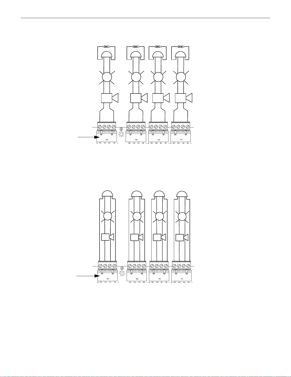
Notification Appliance Circuits Installation
NAC4NAC3
NAC2
NAC1
+
+
+
+
+
+
+
+
+
+
+
+
Figure 2.7 NAC Class B Wiring
4 Class B Notification Appliance Circuits, supervised and power-limited - 4.7 kΩ, ½ watt P/N:71252 UL listed
Polarized Bells
Polarized Bells
Polarized HornsPolarized Horns
Polarized Strobes
Notification Appliance Circuit
polarity shown in alarm state
Dummy Load all unused circuit
TB5
e
s
2
0
0
n
a
c
y
.
w
m
f
Polarized Strobes
circuit number
NAC 1
NAC 2
NAC 3
NAC 4
TB4 TB6 TB7
NAC4NAC3
NAC2
NAC1
+
+
+
+
+
+
+
+
+
+
+
+
4 Class A Notification Appliance Circuits, supervised and power-limited
Polarized HornsPolarized Horns
Notification Appliance Circuit
polarity shown in alarm state
Polarized Bells
Polarized Strobes Polarized Strobes
Figure 2.8 NAC Class A Wiring
NAC 1 NAC 4
TB5 TB7
NAC 2 N AC 3
Dummy Load all unused circuits
Polarized Bells
circuit number
e
s
2
0
0
c
n
a
c
z
.
w
m
f
TB7TB4
2.4.1 Class B NAC Wiring
2.4.2 Class A NAC Wiring
ES-200X Series Manual — P/N LS10131-000FL-E:C 7/25/2018 27
Page 28

Installation Remote Synchronization Output
RTN- OUT-
RTN+OUT+
CNO NC
SUPV
RMT SYNC NAC1
Figure 2.9 Remote Sync Output
Remote
Power
Supply
FACP main
circuit board
Remote Sync Output
Sync Input
4.7 KΩ ELR
e
s
2
0
0
s
y
n
c
.
w
m
f
Optional Class A Return
2.5 Remote Synchronization Output
Synchronization is a feature that controls the activation of notification appliances in such a way that all devices will turn on and off at
exactly the same time. This is particularly critical when activating strobes which must be synchronized to avoid random activation and a
potential hazard to individuals. Devices connected directly to the control panel’s NACs can be synchronized as described in “Type” on
page 76.
Notification appliances connected to FCPS NAC power supplies require synchronization with the FACP’s devices. This can be accomplished by connecting the Remote Synchronization Output from TB8 of the ES-200X to the sync input of the FCPS-24FS6/8 Power Supply. The 24 VDC signal from TB8 follows, that is mimics, the signal on NAC1. This allows the devices connected to the power supply to
be synchronized with the devices connected to NAC1 on the FACP.
The Remote Synchronization Output is power-limited and supervised (refer to “UL Power-limited Wiring Requirements” on page 29)
and can be wired in Class B or Class A. A 4.7 KΩ ELR resistor must be connected to the end of the wiring at the remote power supply
for Class B wiring. Supervision of the remote synchronization is automatically enabled when the remote sync output is enabled. Supervision will be disabled if the output is disabled. For more information on enabling the remote sync output, refer to page 104.
28 ES-200X Series Manual — P/N LS10131-000FL-E:C 7/25/2018
Page 29
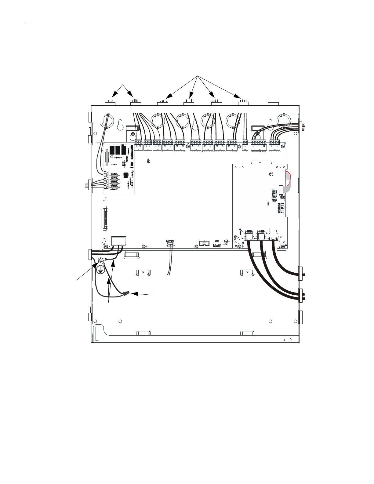
UL Power-limited Wiring Requirements Installation
RTN- OUT-
COMMUNICATOR
DISPLAY
24V
RTN+OUT+
BATTERY
N/L2EARTHH/L1
USB-A
CNO NC
CNO NC
CNCNO
SUPV
TRBL
ALRM
ANN-LC
SLC
RMT SYNC
ANN-BUS PRI
ANN-BUS SEC
NAC4NAC3
NAC2
NAC1
Figure 2.10 Typical UL Power-limited Wiring Requirements
Power-limited Circuits (Class 2)
Powerlimited
Circuits
(Class 2)
AC
Power
Grounding
Stud (see
Figure 2.4)
n
f
w
1
0
0
x
u
l
w
i
r
e
.
w
m
f
To
Batteries
maintain minimum 0.25” between
power-limited and nonpower-limited
circuits wiring
Ground
Cables (2)
#71073
Wire Nut
Nonpower-limited Circuits
Powerlimited
Circuits
(Class 2)
4XTMF
Power-limited
(Class 2)
Supervised
Ethernet Circuit
Nonpowerlimited (Class 1)
Supervised
Telephone
Circuit
IPOTS-COM
2.6 UL Power-limited Wiring Requirements
Power-limited and nonpower-limited circuit wiring must remain separated in the cabinet. All power-limited circuit wiring must remain at
least 0.25” (6.35 mm) away from any nonpower-limited circuit wiring and nonpower-limited circuit wiring must enter and exit the cabinet through different knockouts and/or conduits. When connecting the ground cables, be sure that the AC mains ground is the first one
installed, closest to the backbox. A typical wiring diagram for the ES-200X is shown below.
ES-200X Series Manual — P/N LS10131-000FL-E:C 7/25/2018 29
Page 30
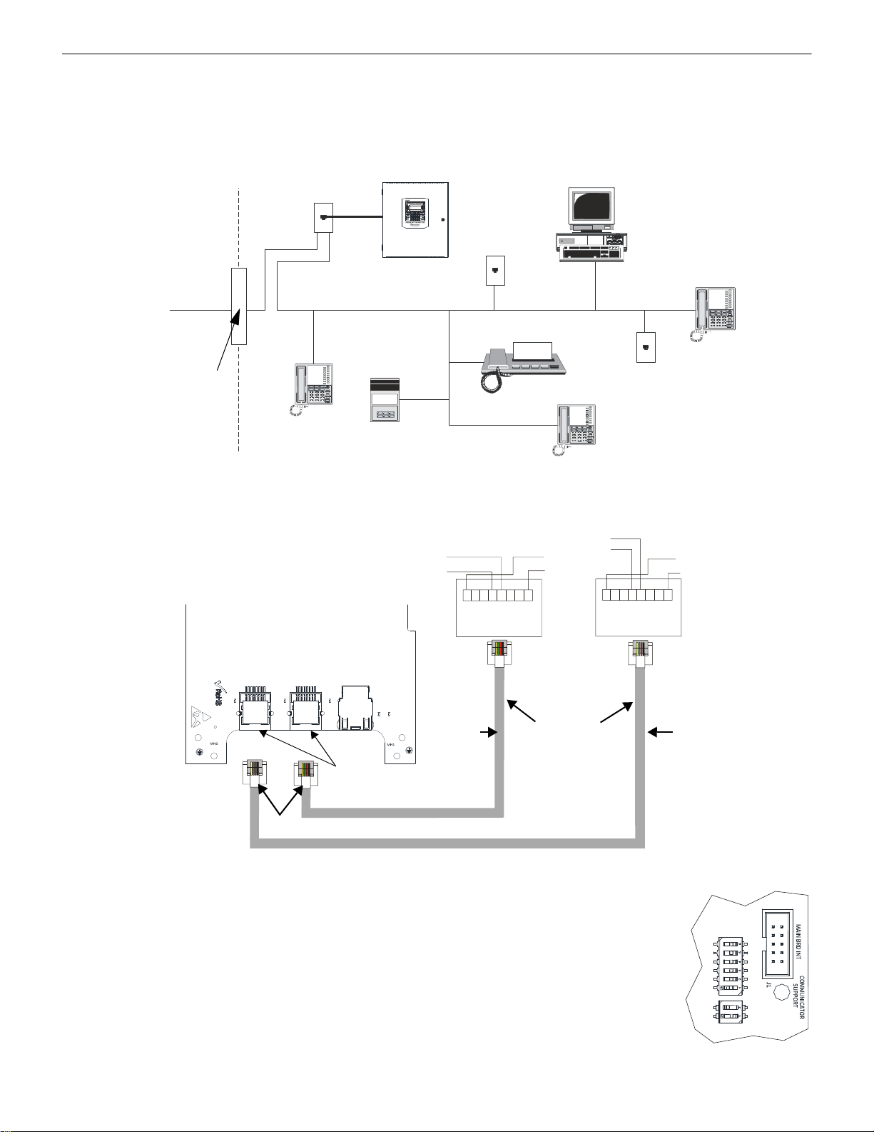
Installation IPOTS-COM Communicator
Figure 2.11 Communicator Installation
Customer Premises Equipment and Wiring
Telephone
Line
FACP with IPOTS-COM
mounted internally
Network
Service
Provider’s
Facilities
Network
Demarcation
Point
RJ31X
Jack
Unused
RJ-11 Jack
Unused
RJ-11 Jack
Telephone
Telephone
Telephone
Answering
System
Fax Machine
Computer
e
s
2
0
0
d
a
c
t
.
w
m
f
123456778
123
4
56 8
LED4
LED5
LED6
LED7
LED8
J3
J5J4
ETHLINE2LINE1
Figure 2.12 Wiring Phone Jacks
Ring
Tip
To premise phones
Ring
Tip
Green Wire
Red Wire
Rin
Ti
Green
Red Wire
(Secondary Lines)
Incoming Telco Phone
Ring
Tip
To premise
(Primary Lines)
Incoming Telco Phone
RJ31X
Jack
RJ31X
Jack
Note: Shorting
bars inside RJ31X
Jack removed
during installation.
7 foot Cable
MCBL-7
(ordered
separately)
Primary Phone Line
Secondary
Phone Line
Module Female
Connectors
Male Plug
Connectors
e
s
2
0
0
j
a
c
k
.
w
m
f
IPOTS-COM
SW2
SW3
Figure 2.13
IPOTS-COM Dip
Switches
S
W
2
S
W
3
2.7 IPOTS-COM Communicator
Two independent telephone lines can be connected to the control panel via the IPOTS-COM Phone/IP Communication Module. Telephone line control/command is made possible via double line seizure as well as usage of an RJ31X style interconnection. Note that it is
critical that the IPOTS-COM Digital Communicator be located as the first device on the incoming t elephone circuit to properly function.
Important! The IPOTS-COM must not be used to dial a phone number that is call-forwarded.
30 ES-200X Series Manual — P/N LS10131-000FL-E:C 7/25/2018
Wiring
Connection and wiring of two phone lines is required as shown below.
Dip Switches
There are two configurable dip switches on the IPOTS-COM communicator.
• SW2: 6-position dip switch- FUTURE USE- No configuration necessary.
• SW3: 2-position dip switch- Factory Settings- Do not change unless instructed to do
so by Honeywell.
Page 31

Optional Module Installation Installation
!
- + A B
-
+
B
A
S
W
2
S
W
3
Figure 2.14 Wiring the CELL-CAB/CELL-MOD
IPOTS-COM
CELL-CAB/CELL-MOD
e
s
t
o
c
e
l
l
c
a
b
.
w
m
f
2.8 Optional Module Installation
WARNING: RISK OF ELECTRIC SHOCK AND EQUIPMENT DAMAGE
DISCONNECT ALL SOURCES OF POWER (AC AND DC) BEFORE INSTALLING OR REMOVING ANY MODULES OR
WIRING.
2.8.1 CELL-CAB-FL/CELL-MOD
The CELL-CAB-FL/CELL-MOD offers an optional GSM communicator card for central station reporting. It mounts in its own plastic
or metal enclosure. Use of the CELL-MOD/CELL-CAB-FL requires the IPOTS-COM communicator.
Installation
Install the CELL-CAB-FL(C) as described in the Product Installation Document #LS10186-000FL-E and the CELL-MOD(C) as
described in #LS10182-000GE-E.
Wiring
Connections are made from TB2 on the IPOTS-COM board to the to terminal on the GSM card as shown below.
2.8.2 PWRMOD24 NAC Expander
The PWRMOD24 is an optional module that provides an additional 3 amps of NAC power.
Installation and Wiring
Install the PWRMOD24 as described in the Product Installation Document #LS10185-000GE-E.
2.8.3 4XTMF Transmitter Module Installation
The 4XTMF provides a supervised output for a local energy municipal box transmitter in addition to alarm and trouble reverse polarity.
A jumper option allo ws the reverse pola rity circu it to open with a system trouble cond ition if no alarm condi tion exists. A disable switch
allows disabling of the transmitter output during testing to prevent accidental calling of the monitoring service.
Local Energy Municipal Box Service (NFPA 72 Auxiliary Fire Alarm Systems):
Supervisory Current: 5.0 mA
Trip Current: 350 mA (subtracted from notification appliance power)
Coil Voltage: 3.65 VDC
Maximum Coil Resistance: 14.6 ohms
Maximum allowable wire resistance between panel and trip coil: 3 ohms
Municipal Box wiring can leave the building
Remote Station Service (NFPA 72 Remote Station Fire Alarm Systems) - Intended for connection to a polarity reversal cir cuit or
a Remote Station receiving unit having compatible ratings:
Maximum load for each circuit: 10 mA
Reverse polarity output voltage: 24 VDC
Remote Alarm and Remote Trouble wiring can leave the building
ES-200X Series Manual — P/N LS10131-000FL-E:C 7/25/2018 31
Page 32

Installation Optional Module Installation
Figure 2.15 4XTMF Transmitter Module
Connect to FACP J12 & J13
Disconnect Switch
shown in
disconnect position
TBL Jumper
}
Remote Alarm (power-limited)*
}
Remote Trouble (power-limited)*
No connection
}
Municipal Box (nonpower-limited)*
1 2 3 4 5 6 7
+ - + - + -
Polarities are shown for module activation
Note: The 4XTMF Module is not directly suitable for transmitting a reverse polarity
supervisory signal. For applications using reverse polarity of a supervisory signal, refer to
“FACP with Keltron” on page 143.
* Wiring from these
terminals can exit the
protected premises.
Dummy load
terminals 6 and 7
(4.7kΩ, ¼ watt
resistor) if Municipal
Box is not connected.
Disconnect LED
4
x
t
m
f
.
w
m
f
Before installing the module, place the disconnect switch to the right (disconnect) position to prevent accidental activation of the municipal box. Note that a Disconnect LED will illuminate after the module is installed in the ES-200X. In addition, the System Trouble LED
will turn on to indicate the Disconnect condition.
The following steps must be followed when installing the 4XTMF module:
1. Remove all power (Primary and Secondary) from the FACP before installing 4XTMF.
2. Carefully plug the connectors on the 4XTMF module into connectors J12 and J13 on the ES-200X main circuit board, being car eful
not to bend any pins.
3. Secure 4XTMF module to standoffs with supplied screws.
4. Slide SW2 on the ES-200X main circuit board to the down position.
5. Enable 4XTMF supervision in user programming. Refer to “4XTMF Supervision” on page 80.
6. Reapply power to the FACP.
7. For proper 4XTMF operation, the output relays must be programmed for the factory default settings: Alarm Relay 1, Trouble Relay
2 and Supervisory Relay 3.
8. When the installation has been complete, enable the 4XTMF module by sliding the disconnect switch to the left.
9. Te st system for proper operation.
32 ES-200X Series Manual — P/N LS10131-000FL-E:C 7/25/2018
Page 33

Optional Module Installation Installation
RTN- OUT-
RTN+OUT+
CNO NC
CNO NC
CNCNO
SUPV
TRBL
ALRM
ES200- PCAREV
ES50- PCA REV
RMT SYNC NAC1
123
Figure 2.16 4XTMF Connectors to ES-200X Connectors
J12 & J13 Connectors
Standoff
Standoff
4XTMF
FACP main circuit board
e
s
2
0
0
4
x
t
m
f
.
w
m
f
Jumper JS3
NOTE: When a 4XTMF is installed, enable supervision in panel programming.
Jumper JS3 on the FACP main circuit board can be used to configure the FACP supervisory relay for operation with the 4XTMF module.
Relay 3 at TB3 must be programmed as a supervisory relay.
Jumpering pins 2&3 on JS3 will allow the 4XTMF to generate a trouble if the supervisory contact opens.
Jumpering pins 1&2 on JS3 in will prevent generation of a trouble if the supervisory contact opens.
2.8.4 ANN-BUS Annunciators/Modules
ANN-BUS Wiring
This section contains information on calculating ANN-BUS wire distances and the types of wiring configurations (Class B).
Calculating Wiring Distance for ANN-BUS Modules
The following instructions will guide the installer in determining the type of wire and the maximum wiring distance that can be used
with FACP ANN-BUS accessory modules.
To c alculate t he wire gauge that must be used to con nect ANN-BUS modules to the F ACP, it is necessary to calcul ate the t otal wo rst case
current draw for all modules on a single 4-conductor bus. The total worst case current draw is calculated by adding the individual worst
case currents for each module. The individual worst case values are shown in the following table:
Model Number Worst Case Current Draw
ANN-80 LCD Annunciator 0.040 amps
ANN-100 LCD Annunciator 0.025 amps
ANN-S/PG Serial/Parallel Printer Interface Module 0.040 amps
ANN-I/O LED Driver Module 0.200 amps
ANN-(R)LED Annunciator Module 0.068 amps
ANN-RLY Relay Module 0.075 amps
1 When powering the ANN-BUS from one of the (nonresettable) DC power outputs at TB11, the
total worst case current draw cannot exceed 1.0 amp. If sharing this DC output with other devices,
the worst case current drawn by these devices must be combined with the ANN-BUS current draw,
and the total cannot exceed 1.0 amp. If the total current demand exceeds 1.0 amp, refer to
“Powering ANN-BUS Devices from an Auxiliary Power Supply” on page 35.
1
ES-200X Series Manual — P/N LS10131-000FL-E:C 7/25/2018 33
Page 34

Installation Optional Module Installation
TB1
4 3 2 1
+ -
Figure 2.17 Primary ANN-BUS wiring to ANN-BUS Device
ANN-BUS Device
ES-200X
ANN-BUS and power wiring are
supervised and power-limited
24 VDC
nonresettable
Primary
ANN-BUS
e
s
2
0
0
t
o
a
n
n
8
0
.
w
m
f
In general, the wire length is limited by resistance, but for heavier wire gauges, capacitance is the limiting factor. Maximum length can
never be more than 6,000 feet (1,800 m), regardless of gauge used. The following formulas were used to generate the wire distances:
Maximum Resistance (Ohms)
Maximum Wire Length (feet)
(6,000 feet maximum) Rpu
=
Total Worst Case Current Draw (amps)
Maximum Resistance (Ohms)
=
x 500
where: Rpu = Ohms per 1,000 feet for various Wire Gauges (see table below)
Wire Gauge Ohms per 1,000 feet (Rpu)
22 16.2
18 6.4
16 4.02
14 2.54
Exception: When using the ANN-RLY module, the installer must ensure that the maximum 24VDC power line drop does not exceed 0.3
volts. This results in the following wiring limitations:
2.0 Volts
Wire Gauge Maximum Wire Length
18 312 feet
16 497 feet
14 787 feet
12 1,250 feet
Wiring Distance Calculation Example:
Suppose a system is configured with the following ANN-BUS modules:
• 3 ANN-80 Remote Fire Annunciators
• 1 ANN-S/PG Serial/Parallel Printer Interface Module
The total worst case current is calculated as follows:
ANN-80 Current Draw = 3 X 0.040 amps = 0.120 amps
ANN-S/PG Current Draw = 1 X.0.040 amps = 0.040 amps
Total Worst Case Current Draw = 0.160 amps
Wiring Configuration
Figure 2.17 illustrates the wiring between the FACP’s Primary ANN-BUS and ANN-BUS devices.
34 ES-200X Series Manual — P/N LS10131-000FL-E:C 7/25/2018
Page 35

Optional Module Installation Installation
TB1
4 3 2 1
+ -
Figure 2.18 Secondary ANN-BUS wiring to ANN-BUS Device
ANN-BUS Device
ES-200X
ANN-BUS and power wiring are
supervised and power-limited
24 VDC
nonresettable
Secondary
ANN-BUS
e
s
2
0
0
t
o
a
n
n
8
0
2
.
w
m
f
TB1
4 3 2 1
1 2 3 4 5 6 7 8
ON
SW1
TB4
JP3
J3
TB5
TB2
JP1
JP2
OUT4
- NAC4 +
OUT3
- NAC3 +
OUT2
- NAC2 +
OUT1
- NAC1 +
8 7 6 5 4 3 2 1
3 2 1
10
9
8
7
6
5
4
3
2
1
AUX -
IN2-
IN2+
OUT1-
OUT1+
IN1-
IN1+
SYNC IN -
SYNC IN +
AUX +
NO NC
AUX TBL
COM
-
Figure 2.19 Powering ANN-BUS Devices from FCPS-24FS6/8
ANN-80
ES-200X
FCPS-24FS6/8
-24 VDC
+24 VDC nonresettable
Cut Ground Fault Detection jumper JP1
(FACP monitors for ground faults).
ANN-BUS and power wiring are
supervised and power-limited
9
2
u
d
b
l
s
C
t
o
f
c
p
s
t
o
a
n
n
.
w
m
f
Primary
ANN-BUS
Figure 2.18 illustrates the wiring between the FACP’s Secondary ANN-BUS and ANN-BUS devices.
Powering Both ANN-BUS Circuits Simultaneously
When simultaneously using the Primary and Secondary ANN-BUS circuits on the FACP, power can be shared from the Nonresettable
Power output on TB11. Alternately, one ANN-BUS can be powered by the Resettable Power output (TB11 Terminals 3 and 4) once it is
reconfigured as Nonresettable Power in panel programming. This provides the benefit of independently acting power-limiting for the
two ANN-BUS circuits (required for Canadian applications).
Powering ANN-BUS Devices from an Auxiliary Power Supply
Figure 2.19 illustrates the powering of ANN-BUS devices from an auxiliary power supply such as the FCPS-24FS6/8, when the total
ANN-BUS power requirements exceed the panel’s DC Power Output capability.
ES-200X Series Manual — P/N LS10131-000FL-E:C 7/25/2018 35
Page 36

Installation Optional Module Installation
a
n
n
-
8
0
_
i
s
o
2
.
w
m
f
Key switch shown in
OFF/Locked position
Press in latch
and
Pull annunciator
cover open
Annunciator cover
with LCD display
Annunciator backplate
ANN-BUS Device Addressing
Each ANN-BUS device requires a unique address (ID Number) in order to communicate with the FACP. A 5-position DIP switch on
each device is used to set this address. The address set for these devices must also be programmed at the FACP for the specific device
(refer to the programming section titled “ANN-BUS Setup” on page 90).
A maximum of 8 devices can be connected to each FACP ANN-BUS communication circuit. Device addresses do not need to be sequential and can be set to any number between 01 and 08. This applies to both ANN-BUS communication circuits. Note that 00 is not a valid
address. The following table shows the DIP switch setting for each address.
NOTE: Address (ID Number) DIP switches on some devices may have more than 5 switch positions. Unless otherwise specified in the
documentation supplied with each device, switch positions 6 and above must be set to OFF.
Address Switch 5 Switch 4 Switch 3 Switch 2 Switch 1
not valid OFF OFF OFF OFF OFF
01 OFF OFF OFF OFF ON
02 OFF OFF OFF ON OFF
03 OFF OFF OFF ON ON
04 OFF OFF ON OFF OFF
05 OFF OFF ON OFF ON
06 OFF OFF ON ON OFF
07 OFF OFF ON ON ON
08 OFF ON OFF OFF OFF
Switch 5 must be set to OFF for ANN-BUS devices to be recognized.
ANN-80 Remote Fire Annunciator
Specifications
• Operating Voltage Range: 18 VDC to 28 VDC
• Current Consumption @ 24 VDC nominal (filtered and nonresettable):
– Normal/Standby (no activity): 37 mA
– Trouble: 39 mA
– Alarm: 40 mA
– AC Fail (not backlit): 15 mA
• For use indoors in a dry location
Installation
Ensure that all power (AC and DC) has been removed from the FACP before installing the annunciator.
Opening/Closing Annunciator
The following procedure details the steps used to open the annunciator in order to access the terminal block and DIP switches (refer to
figure below):
1. Turn the key switch to the ON (Unlocked) position by turning the key counter-clockwise.
2. Push in the snap latch located on the right side of the unit while pulling the cover open.
3. To close the cover, make certain the key switch is in the ON (Unlocked) position. Swing the cover closed, snapping it shut.
4. Turn the key switch to the OFF (Locked) position by turning clockwise and remove the key.
36 ES-200X Series Manual — P/N LS10131-000FL-E:C 7/25/2018
Page 37

Optional Module Installation Installation
a
n
n
8
0
k
i
t
m
o
u
n
t
.
w
m
f
Annunciator mounted on
surface wedge from the
ANN-SB80KIT
Annunciator mounted on stacked
surface wedge and backbox from
the ANN-SB80KIT
Annunciator mounted on
surface backbox from the
ANN-SB80KIT
wiring channel
wires
TB1
a
n
n
-
8
0
b
o
x
i
n
s
i
d
e
.
w
m
f
Mounting
The ANN-80 can be surface or semi-flush mounted to a single, double or 4” square electrical box. Select and re move the appropriate
knockout(s), pull the necessary wires through the knockouts and mount the annunciator in or on the wall depending on the type of installation desired.
The ANN-SB80KIT(-R/-B/-W) is an available mounting kit for the ANN-80 annunciator . The kit comes with a surface backbox and surface wedge for angled viewing. The two pieces can be used separately or can be stacked together.
The ANN-80 cover must be attached to the annunciator backplate before mounting the annunciator to the electrical box/wall. The cover
cannot be reattached or removed after the annunciator has been mounted.
Wiring ANN-80 to FACP
The following steps can be used as a guide to wire the annunciator. Make certain all power has been removed from the FACP prior to
annunciator installation.
1. Route wires from hole in backplate, through wiring channel and then to ANN-80 terminal block TB1
2. Remove appropriate amount of wire insulation
3. Connect the wiring from the FACP ANN-BUS to annunciator TB1 terminals 3 (A) & 4 (B). Make certain to connect A to A and B
to B
4. If appropriate, connect the wiring going to the next device on the ANN-BUS to TB1 terminals 3 & 4. Make certain to connect A to
A and B to B
5. Connect the wiring from the 24 VDC power source to annunciator TB1 terminals 1 (-) & 2 (+). Make certain to observe proper
polarity
6. If appropriate, connect the power wiring going to the next device to terminals
1 (-) & 2 (+). Make certain to observe proper polarity
ES-200X Series Manual — P/N LS10131-000FL-E:C 7/25/2018 37
Page 38

Installation Optional Module Installation
Figure 2.20 ANN-80 Wiring to FACP
TB1
4 3 2 1
+ -
ANN-BUS Device
ES-200X
ANN-BUS and power wiring are
supervised and power-limited
24 VDC
nonresettable
Primary
ANN-BUS
9
e
s
2
0
0
t
o
8
0
.
w
m
f
7. After all connections are made, remove extra wire from inside of annunciator by dressing it neatly through wire channel, with any
excess wire pushed back through hole into electrical box
The following table shows the ANN-80 connections to the ES-200X.
ES-200X ANN-80 (TB1)
Terminal GND (-) on TB11 Terminal 1 (-)
Terminal PWR (+) on TB11 Terminal 2 (+)
Terminal Data (A) on TB9 Terminal 3 (A)
Terminal Data (B) on TB9 Terminal 4 (B)
Programming
Following installation and wiring of the ANN-80 LCD annunciator to the FACP, the annunciator must be added to the system via FACP
programming. Refer to the programming section titled “ANN-BUS Setup” on page 90 in this manual for detailed programming information.
Trouble Response
If the ANN-80 is installed but the ANN-BUS is not enabled at the FACP, the ANN-80 will indicate a trouble condition by NOT turning
on its AC Power indicator. The LCD will also display Key Bus Trouble and the piezo will sound approximately once every 10 seconds.
Note that the FACP will provide no indication of an ANN-80 trouble.
To clear the ANN-80 trouble condition, enable the ANN-BUS and program the address corresponding to the address set on the ANN-80
at the FACP.
ANN-100 Remote Fire Annunciator
Specifications
• Operating Voltage: 24 VDC
• Current
– Standby: 20 mA
– Alarm: 25 mA
• Ambient Temperature: 32°F to 120°F (0°C to 49°C)
• Max. Wiring Distance from FACP: 6,000 ft. (1,800 m)
• Mounting: Surface or Flush-mount
• Dimensions: 12-1/4”W x 11-1/2”H x 7/8”D (31.1 cm W x 29.2 cm H x 2.2 cm D)
• For indoor use in a dry location only
The following table shows the ANN-100 connections to the ES-200X.
Terminal GND (-) on TB11 Terminal 1 (-)
Terminal PWR (+) on TB11 Terminal 2 (+)
Terminal Data (A) on TB9 Terminal 3 (A)
Terminal Data (B) on TB9 Terminal 4 (B)
ES-200X ANN-100 (TB1)
38 ES-200X Series Manual — P/N LS10131-000FL-E:C 7/25/2018
Page 39

Optional Module Installation Installation
(-)
(+)
A
B
Figure 2.21 ANN-S/PG Connection to FACP
ANN-S/PG Module
ES-200X
Cable Connectors for
connection to printer
Parallel
Serial
ANN-BUS and power wiring are
supervised and power-limited
24 VDC
nonresettable
Primary
ANN-BUS
9
2
u
d
b
l
s
c
t
o
s
p
g
.
w
m
f
Programming
Following installation and wiring of the ANN-100 LCD annunciator to the FACP, the annunciator must be added to the system via F ACP
programming. Refer to the programming section titled “ANN-BUS Setup” on page 90 in this manual for detailed programming information.
Trouble Response
If the ANN-100 is installed but the ANN-BUS is not enabled at the FACP, the ANN-100 will indicate a trouble condition by NOT turning on its AC Power indicator. The LCD will also display Key Bus Trouble and the piezo will sound approximately once every 10 sec-
onds. Note that the F A CP will provide no indication of an ANN-100 trouble.
To clear the ANN-100 trouble condition, enable the ANN-BUS and program the address corresponding to the address set on the ANN100 at the FACP.
ANN-S/PG Serial/Parallel Interface Module
Installation
1. Ensure that all power (AC and DC) has been removed from the FACP.
2. Connect the ANN-S/PG to the FACP as illustrated in Figure 2.21
3. Using the DIP switches on the back of the ANN-S/PG module, assign an ID number (address) to the module.
4. Select the address and configuration options for the ANN-S/PG module as described in the Programming section of this manual
(refer to “ANN-BUS Setup” on page 90).
Note that the Auto-configure feature allows the programmer to quickly bring all installed ANN-BUS modules online (refer to
“Auto-Configure” on page 97).
5. Connect a printer to the ANN-S/PG Parallel or Serial connectors (refer to Figure 2.21). Only one printer can be connected.
Specifications
• Operating Voltage: 24 VDC
• Current (Alarm and Standby): 45 mA
• Ambient Temperature: 32°F to 120°F (0°C to 49°C)
• Max. Wiring Distance from FACP: 6,000 ft. (1,800 m)
• Mounting: Surface
• Dimensions: 6”W x 7-3/4”H x 1-7/16”D (15.2 cm W x 19.7 cm H x 3.7 cm D)
• For indoor use in a dry location only
Connecting a PRN-7 Printer
Remote printers require a primary AC power source. If required for the fire alarm system configuration (for example, a Proprietary Fire
Alarm System), a remote printer requires a secondary power source (battery backup). Since a secondary power source is not provided as
a standard feature, a separate UL-listed Uninterruptible Power Supply (UPS) should be used. The building emergency power supply may
be used, as long as it meets the power continuity requirements of NFPA 72. Refer to NFPA 72 for further details.
Connect the remote printer to the FACP via the ANN-S/PG module using a standard DB-9 cable. One end of the cable will plug into the
DB-9 connector on the PRN-7 printer and the other end plugs into the serial connector on the ANN-S/PG module.
ES-200X Series Manual — P/N LS10131-000FL-E:C 7/25/2018 39
Page 40

Installation Optional Module Installation
Setting Printer Options
Refer to the documentation supplied with the PRN-7 printer for instructions on using the printer menu controls. Set the printer options
(under the menu area) as shown in the following table:
Option Setting Option Setting
Font HS Draft CPI 10CPI
LPI 6 LPI Skip 0.5
ESC Character ESC Emulate LQ-2550
Bidirectional Copy ON I/O
CG-TAB Graphic Buffer 64K
Country E-US ASCII Serial
Auto CR OFF Baud 9600 or 2400
Color Option Not Installed Format 7 Bit, Even, 1 Stop
Formien Protocol XON/XOFF
Lines 6LPI=60 Character Set Standard
Standard Exec 10.5 SI.Zero On
Barcode Off Auto LF On
Barcode Unsecured
Table 2.1 PRN-7 Setup Options
PRN-6F Printer Installation
When connected to the FACP via the ANN-S/PG module, the PRN-6F prints the status changes within the control panel and time-stamps
the printout with the time of day and date that the event occurred. It provides 80 columns of data on standard 9” x 11” tractor -feed paper.
This section contains information on connecting a printer to the control panel and setting the printer options.
Connecting PRN-6F Printer
Remote printers require a primary AC power source. If required for the fire alarm system configuration (for example, a Proprietary Fire
Alarm System), a remote printer requires a secondary power source (battery backup). Since a secondary power source is not provided as
a standard feature, a separate UL-listed Uninterruptible Power Supply (UPS) should be used. The building emergency power supply may
be used, as long as it meets the power continuity requirements of NFPA 72. Refer to NFPA 72 for further details.
Connect the remote printer to the FACP via the ANN-S/PG module using a standard DB-25 cable. One end of the cable will plug into the
DB-25 connector on the PRN printer and the other end plugs into the parallel connector on the ANN-S/PG module. Note that the 9-pin
DB-9 port on the ANN-S/PG is used to connect a serial printer. The 25-pin port is used for a Centronics parallel printer cable. Connect
either a serial or parallel printer, but not both at the same time.
Setting Printer Options
Refer to the documentation supplied with the PRN-6F printer for instructions on using the printer menu controls. Set the printer options
(under the menu area) as shown in the following table:
Option Setting Option Setting
Font HS Draft CPI 10CPI
LPI 6 LPI Skip 0.5
ESC Character ESC Emulate Epson FX-850
Bidirectional Copy ON I/O
CG-TAB Graphic Buffer 40K
Country E-US ASCII Serial
Auto CR OFF Baud 9600 or 2400
Color Option Not Installed Format 7 Bit, Even, 1 Stop
Formien Protocol XON/XOFF
Lines 6LPI=60 Character Set Standard
Standard Exec 10.5 SI.Zero On
Auto LF On
PAPER
BIN 1 12/72”
BIN 2 12/72”
SINGLE 12/72”
PUSH TRA 12/72”
PULL TRA 12/72”
PAP ROLL 12/72”
Table 2.2 PRN -6 Setup Options
40 ES-200X Series Manual — P/N LS10131-000FL-E:C 7/25/2018
Page 41

Optional Module Installation Installation
1
10
11
20
21
30
31
40
LED Out
LED Power
not used
LED Out
LED Power
not used
LED Out
LED Power
not used
LED Out
LED Power
not used
ANN-BUS (ID#)
Address Dip switch
ANN-BUS Connector
a
n
n
-
i
o
b
r
d
2
.
w
m
f
Figure 2.22 ANN-I/O Board Layout
ANN-I/O LED Driver Module
ANN-I/O Board Layout
Figure 2.22 illustrates the ANN-I/O board showing locations of screw terminals for connection to the FACP, pin connectors for connecting LEDs and the DIP switch for selecting the ANN-BUS ID number.
Specifications
• Max. ANN-BUS Voltage: 24 VDC
• Max. Current:
Alarm: 200 mA
Standby: 35 mA
Each LED: 10 mA
• Operating Temperature: 32°F to 120°F (0°C to 49°C)
• For indoor use in a dry location only
ES-200X Series Manual — P/N LS10131-000FL-E:C 7/25/2018 41
Page 42

Installation Optional Module Installation
P1
P2
P3
P4
12345
+ -
Figure 2.23 ANN-I/O Connection to FACP
ANN-I/O Module
ANN-BUS and power wiring are
supervised and power-limited
e
s
2
0
0
t
o
a
n
n
i
o
.
w
m
f
Primary ANN-BUS
24 VDC nonresettable
LED Out
LED Power
Not Used
LED Out
LED Power
Not Used
LED Out
LED Power
Not Used
LED Out
LED Power
Not Used
101112020
21
303140
ANN-I/O Connection to FACP
The ANN-I/O connects to the F A CP via th e ANN-BUS as illustrated in Figure 2.23. After the ANN-I/O is connec ted to the pa nel, it mus t
be added to the system via FACP programming. Refer to the section titled “ANN-I/O Options” on page 91.
ANN-I/O Module LED Wiring
There are four 12-pin connectors on the ANN-I/O module for connecting LEDs. Each set of 10 LEDs get their power from Pin 11 of the
corresponding connector. Internal resistors are sized so that there is approximately 10 mA of current for each LED. No series resistors
are required. LED outputs can be mapped to output circuits. Refer to the programming sect ion title d “ ANN-I/O Options” on page 91 of
this manual.
The LEDs are wired as illustrated in Figure 2.24. Note that the illustration depicts only connectors P1 and P2. Wiring is identical for P3
(LEDs 21-30) and P4 (LEDs 31-40).
42 ES-200X Series Manual — P/N LS10131-000FL-E:C 7/25/2018
Page 43

Optional Module Installation Installation
Figure 2.24 ANN-I/O LED Wiring
a
n
n
-
i
o
l
e
d
s
2
.
w
m
f
LED1
LED2
LED3
LED4
LED5
LED6
LED7
LED8
LED9
LED10
LED Power
no connection
Pin #
1
2
3
4
5
6
7
8
9
10
11
12
LED11
LED12
LED13
LED14
LED15
LED16
LED17
LED18
LED19
LED20
LED Power
no connection
P1
P2
Pin #
1
2
3
4
5
6
7
8
9
10
11
12
Cathode
LEDs
Anode
Cathode
LEDs
Anode
Figure 2.25 ANN-LEDs (shown in possible stacked configuration)
a
n
n
-
l
e
d
s
t
a
c
k
e
d
.
w
m
f
ES-200X Series Manual — P/N LS10131-000FL-E:C 7/25/2018 43
ANN-LED Annunciator Module
Page 44

Installation Optional Module Installation
Figure 2.26 Exploded View of ANN-LED
a
n
n
-
l
e
d
.
w
m
f
TB1
J1
SW1
JP2
ANN-BUS
1 2 3 4 5 6 7 8
+ -
Figure 2.27 ANN-LED Board Layout and Connection to FACP
ES-200X
e
s
2
0
0
t
o
l
e
d
.
w
m
f
ANN-LED
Primary ANN-BUS
-24 VDC
+24 VDC
ANN-BUS and power wiring are
supervised and power-limited
ANN-BUS (ID#)
Address DIP switch
Specifications
• Max. ANN-BUS Voltage: 24 VDC
• Max. Current:
Alarm: 68 mA
Standby: 28 mA
• Operating Temperature: 32°F to 120°F (0°C to 49°C)
• For indoor use in a dry location only
Mounting/Installation
The ANN-LED Module is supplied with a metal backbox, mounting bracket, and cover. Refer to the ANN-LED Installation Document
#53032 for more information.
ANN-LED Board Layout and Connection to FACP
Figure 2.27 illustrates the ANN-LED board showing locations of screw terminals for connection to the FACP and the DIP switches for
selecting the ANN-BUS ID number.
44 ES-200X Series Manual — P/N LS10131-000FL-E:C 7/25/2018
Page 45

Optional Module Installation Installation
mounting holes
mounting hooks through
mounting slots
grounding wire
ANN-RLY
ANN-MBRLY
mounting bracket
mounting holes
mounting holes
FACP Backbox Installation
using ANN-MBRLY mounting bracket
FACP Chassis Installation
mounting holes
mounting holes
ANN-RLY on
ANN-MBRLY
mounting bracket
ROME Series Installation
using ANN-MBRLY mounting bracket
Figure 2.28 ANN-RLY Mounting Options
ANN-RLY Annunciator Module
Specifications
• Operating Voltage: 24 VDC
• Max. Current:
Alarm: 75 mA
Standby: 15 mA
• Operating Temperature: 32°F to 120°F (0°C to 49°C)
• For indoor use in a dry location only
Mounting/Installation
The ANN-RLY relay module can be mounted inside the FACP main circuit board chassis or inside the ROME Series enclosure. Refer to
the ANN-RLY Installation Document #53033 for instructions on chassis mounting or to the ROME Series Installation Document #53530
for mounting in the separate backbox.
ES-200X Series Manual — P/N LS10131-000FL-E:C 7/25/2018 45
Page 46

Installation Optional Module Installation
TB1
J1
SW1
JP2
ANN-BUS
1 2 3 4 5 6 7 8
TB6
TB3
TB5
TB4
TB2
+ -
Figure 2.29 ANN-RLY Board Layout and Connection to FACP
ANN-RLY
Primary
ANN-BUS
-24 VDC
+24 VDC
ANN-BUS and power wiring are
supervised and power-limited
e
s
2
0
0
t
o
r
l
y
.
w
m
f
ES-200X
ANN-BUS (ID#)
Address DIP switch
!
ANN-RLY Board Layout and Connection to FACP
Figure 2.29 illustrates the ANN-RLY board showing locations of screw terminals for connection to the FACP and the DIP switches for
selecting the ANN-BUS ID number.
2.8.5 Printer
A parallel printer may be connected to the FACP using the optional ANN-S/PG Serial/Parallel Interface Module. The printer can be used
to provide a hard-copy printout of real-time events, history file and walktest data. Installation of the device requires panel programming
to allow the FACP to communicate with the device. Refer to “ANN-S/PG Serial/Parallel Interface Module” on page 19 for installation
details. Refer to “ANN-BUS Setup” on page 90 for programming information.
CAUTION: POSSIBLE EQUIPMENT DAMAGE
DO NOT CONNECT A PRINTER OR PC TO THE ES-200X FACP IF A GROUND FAULT (ZERO IMPEDANCE TO
GROUND) EXISTS ON THE CONTROL PANEL. CIRCUIT DAMAGE MAY RESULT. REMOVE ALL POWER (PRIMARY
AND SECONDARY) BEFORE INSTALLING OR REMOVING ANY WIRING.
Printer Configuration
Refer to the documentation supplied with the printer for pertinent information about printer setup. Set the printer’ s options as listed in the
following table:
COMMUNICATION SETUP
BUFFER: LARGE
DATA BITS: 7
PARITY: EVEN
STOP BIT: 1 STOP
BAUD RATE: 2400/4800/9600
AUTOMATIC LINE FEED NO
AUTOMATIC CARRIAGE RETURN NO
Table 2.3 Printer Options
46 ES-200X Series Manual — P/N LS10131-000FL-E:C 7/25/2018
Page 47

Automatic Audio Panel Control Installation
-+AB
ES-200X
ECC-FFT
Figure 2.30 ECC-FFT Connections
e
s
2
0
0
t
o
f
f
t
.
w
m
f
out to next
SLC device
Figure 2.31 W-GATE SLC Connection
e
s
2
0
0
t
o
W
G
.
w
m
f
ES-200X
W-GATE
mounting plate
2.8.6 ECC-FFT Firefighter Telephone
The ECC-FFT connects from TB11 (non- resettable aux power) on the FACP to the DC Power input on the ECC-FFT board.
2.8.7 W-GATE Wireless Gateway
The W -GATE connects to the FACP’s SLC connection a t TB10. The W-GATE can be powered by either the SLC or an external 24 VDC
power source. A maximum of 100 wireless devices can be used in the system. Refer to the SWIFT® Smart Wireless Integrated Fire
Technology Manual for more information.
NOTE:
(FCC) requirements of the United States Government. It has not been evaluated for use outside the USA. Use of this system outside the
USA is subject to local laws and rules to which this product may not conform. It is the sole responsibility of the user to determine if this
product may be legally used outside the USA.
2.9 Automatic Audio Panel Control
The FACP annunciator bus serves as the “FACP Data Bus” to the ECC-50/100 or ACC-25/50 audio system. User programming is
required to set up the operation of the audio system. To set up the annunciator bus, refer to Section 2.8.4 on page 33. The annunciator
protocol, ANN-Bus, must be selected and enabled.
The W-GATE, as part of the wireless network, has been tested for compliance with the Federal Communications Commission
The F ACP will automatically detect the audio system connection during annunciator “auto-configuration”. No ANN-Bus address selection is necessary at the FACP.
Once the F A CP can communicate with the audio system, F ACP zones Z33 through Z56 become automatically dedicated as output zones
for speaker circuits 1 through 24 respectively. FACP zone Z32 is dedicated to turn on all speaker circuits. FACP programming allows
association between any addressable SLC input device (module, detectors) with any of the speaker circuits. In addition 1 of 14 messages
ES-200X Series Manual — P/N LS10131-000FL-E:C 7/25/2018 47
Page 48

Installation Automatic Audio Panel Control
A B
Figure 2.32 FACP Connection to ECC-50/100 Series Audio Panel
e
s
2
0
0
e
c
c
.
w
m
f
ES-200X
ECC-50/100
to other ANN
devices
1 2 3 4 5 6 7 8
ON
S1
ON
S3
0
5
4
3
2
1
9
8
7
6
0
5
4
3
2
1
9
8
7
6
S2
TENS
ONES
+ -
A (+)
B (-)
ACC-ZPMK
on ACC-25/50ZS(T) Series
Figure 2.33 FACP Connection to ACC-25/50ZS(T) Series Audio Panel (Legacy)
Primary ANN-BUS
e
s
2
0
0
z
p
m
k
.
w
m
f
ES-200X
(1 of 5 using the legacy ACC panel) can be generated over the selected speaker circuit. Any fault in the ECC-50/100 audio system is sent
to the FACP via the FACP Data Bus and is indicated as an annunciator fault on the FACP display. A fault at the ACC-25/50ZS Series
panel will cause the FACP to indicate a System Trouble and the display will indicate a Voice Evac Fault.
For speaker circuit mapping and audio message assignment, refer to “Zone Message” on page 70. Also, refer to “Programmed Activation by FACP” in chapter 3 of the ECC-50/100 Instruction Manual (Doc. LS10001-000FL-E) or Appendix D, “Programmed Activation
by F ACP” in the ACC-25/50ZS Series Instruction Manual (Doc. 51889).
Connect the ECC-50/100 panel’s FACP Data Bus at TB13 to TB9 on the ES-200X FACP.
The only connection between the FACP and ACC-25/50ZS Series audio panel is a pair of communication wires connected between the
A(+)/B(-) terminals on TB9 of the FACP and TB1 terminals 2 & 3 of the ACC-ZPMK module on the audio panel.
48 ES-200X Series Manual — P/N LS10131-000FL-E:C 7/25/2018
Page 49

Section 3: Programming
NOTICE TO USERS, INSTALLERS, AUTHORITIES HAVING JURISDICTION AND OTHER INVOLVED PARTIES
This product incorporates field-programmable software. In order for the product to comply with the requirements in the Standard for Control Units
and Accessories for Fire Alarm Systems, UL 864, certain programming features or options must be limited to specific values or not used at all as
indicated below:
Program feature or
option
Trouble Call Limit N Refer to “Trouble Report Limit (Dialer Runaway Prevention)” on
AC Fail Delay Timer Y Refer to “AC Loss Delay” on page 7 5.
Remote Download Y Refer to “FS-Tools Upload/Download” on page 123.
Control Module
Delay
Cell/Ethernet
Supervision Options
Trouble Reminder
(when used with
SWIFT wireless
devices)
4XTMF Supervision Y Refer to “4XTMF Supervision” on page 80.
Supervised Phone
Line
Test Time Interval Y Refer to “Test Time Interval” on page 85.
Annunciator Lock
Enable
Canadian Option N (UL864)
Permitted in
UL864/ULC527?
(Y/N)
page 86.
• Trouble Call Limit = 0 (factory default): unlimited calling to
Central Station for any trouble condition
• Trouble Call Limit = 1 - 99: limits call for each unique trouble
to from 1 to 99 within a 24 hour period
• 0-23 hours
• Remote Download - Proprietary No
• Remote Download - Proprietary Yes
N Refer to “Control Module Delay” on page 75.
Y Refer to “Supervision Settings” on page 86 and page 86
Y Refer to “Trouble Reminder” on page 80
Y Refer to “Supervised Phone Line” on page 82.
Y Refer to “Lock Enable Option” on page 99.
Y (ULC527)
• Control Module Delay = 0 (factory default): no delay in Control
Module activation
• Control Module Delay = 1-180: delays control module
activation from 1-180 seconds
• NFPA 2010 Dual Path: Supervision Interval: 24 Hours
• NFPA 2010 Sole Path: Supervision Interval: 5 min
• NFPA 2013 Dual Path: Supervision Interval: 6 Hours
• NFPA 2013 Sole Path: Supervision Interval: 1 Hour
• 4 hours
• 24 hours
• Enabled Y es
• Enabled No
• Supervised Y es
• Supervised No
• 24 hours
• 12 hours
• 8 hours
• 6 hours
• Enabled Y es
• Enabled No
Refer to “Canadian Option” on page 79.
•On
•Off
Possible settings
Settings permitted in
UL 864 / ULC527
Trouble Call Limit = 0 for unlimited
Central Station trouble calls
1-3 hours
Remote Download
Proprietary system intended to protect
only contiguous properties
Control Module Delay = 0 for no delay
in control module activation
Any setting is permitted per UL864.
For ULC applications, the supervision
interval for panels communicating in
Sole Path (Cellular-only or Ethernetonly method) is fixed at 3 minutes and
cannot be changed, regardless of
setting option, when the Canadian
Option is enabled.
4 hours
Enabled Y es when the 4XTMF module
is installed.
Supervised Yes if transmission
method is POTS.
6 hours
Enabled Y es
Off (UL864)
On (ULC527)
Proprietary Yes
for
3.1 Programming Data Entry
Programming can be accomplished using the ES-200X keypad or by connecting an optional standard computer keyboard. The keyboard
can be connected to the USB connector J20 on the control panel main circuit board.
The information presented in this section refers to programming the ES-200X via the onboard keypad. If an optional computer keyboard
is connected to the ES-200X main circuit board, the following table describes the keyboard keys which correspond to the onboard keypad keys.
Keypad Keys Computer Keyboard Keys
First Event Home
ES-200X Series Manual — P/N LS10131-000FL-E:C 7/25/2018 49
Page 50

Programming User Programming
SYSTEM NORMAL
10:00A 010118
1=READ STATUS MODE
2=PROGRAMMING MODE
3=FSTOOL UP/DOWNLOAD
4=USB UP/DOWNLOAD
Last Event End
Clear Delete
ESC Esc
RECALL Insert
**
##
@@
A - Z A - Z
0 - 9 0 - 9
■
(on YZ key) Space bar
——
//
••
ENTER Enter
F1 F1
F2 F2
F3 F3
F4 F4
ACK/STEP F5
SILENCE F6
DRILL F7
RESET F8
3.2 User Programming
The ES-200X is completely field programmable and requires no special software skills. While programming the ES-200X, the fire protection capabilities of the control panel are
Site-specific programming may be accomplished in any of the following ways:
• Autoprogramming Feature - This is a convenient method for quickly bringing the F ACP addressable SLC devices on-line without
the necessity of programming each device individually. Refer to “Autoprogram” on page 52 for a detailed description of
Autoprogramming.
• Manual programming or editing, using the FACP keypad or a PC keyboard
• Remote Programming and Editing Feature - allows creation and editing of site-specific custom programs using a Windows-based
computer and Ethernet connection. For programs requiring a large amount of data entry, this method may be preferred. The FSTools programming utility can be downloaded from www.firelite.com for this purpose.
• Local Programming and Editing Feature - allows creation and editing of site-specific custom programs using a Windows-based
computer and the FACP USB connection. For programs requiring a large amount of data entry, this method may be preferred. The
FS-Tools programming utility can be downloaded from www.firelite.com for this purpose.
•The System Normal screen will be displayed in a programmed system with no active alarms, troubles or supervisories, as illustrated
below:
Read Status mode can be entered while the panel is in any
event must be cleared before entering Programming mode. To access any of the programming or read status features, the Enter or Mode
key must be pressed, which will cause the LCD to display the following:
enabled.
mode of operation. If an alarm or supervisory event exists at the panel, the
50 ES-200X Series Manual — P/N LS10131-000FL-E:C 7/25/2018
Page 51

Initial Power-up Programming
1=FIRMWARE UPGRADE
TROUBL IN SYSTEM
NO DEVICES INSTALLED
09:03A 050417
Pressing 1, while this screen is being displayed, will cause the control panel to enter the Read Status Mode which allows the user to view
the programmed features and status of the control panel The Read Status feature is not password protected. Refer to “Read Status” on
page 114 for a detailed description of this feature.
Pressing 2 will select user Programming Mode which may only be accomplished by an authorized person. After pressing 2, a screen will
prompt for a password. After entering the correct password, the user may select from a list of programming options.
Pressing 3 will select Upload/Download via FS-Tools which allows the user to enable the remote programming option. Refer to “FSTools Upload/Download” on page 123.
Pressing 4 will select USB Up/Download which allows the user to upload or download FACP programming via the USB port. See “USB
Upload/Download” on page 125.
The down arrow which appears in the display indicates that additional programming choices can be viewed by pressing the down arrow
key on the keypad. If a down and up arrow appear in the display, pressing the ‘down’ arrow key will display the subsequent Programming Screens as illustrated below while pressing the ‘up’ arrow key will display the previous screen.
Pressing the down arrow displays the following screen:
Pressing 1, while this screen is being displayed, allows the user to upgrade the panel software. Refer to “Firmware Upgrade” on
page 127.
Exit Programming, Read Status
The programmer can exit any mode by repeatedly pressing the keypad ESC (Escape) key until the display reads System Normal. Note
that the data which is entered during Prog ramming mode is not saved until the programmer exits this mode by repeatedly pressing the
‘ESC’ key. If the Reset key is pressed or power is lost before exiting Programming mode, all data just entered will be lost.
User Programming Levels
There are two user programming levels:
• User Master Program Level 1 is used for programming panel specific data relating to device types, zoning, messages, control panel
functions, etc.
• User Maintenance Program Level 2 is used by a qualified operator to access features such as Disable/Enable, View and Clear
History, Walktest and System Time Change.
3.3 Initial Power-up
The following sections describe the initial programming procedures for a new system. The same procedures are used to modify programming in an existing system.
After completing the wiring of addressable devices to the SLC, apply power to the control panel. If the addressable devices have not yet
been programmed into the FACP, their LEDs will not flash and the following trouble message will be displayed.
3.4 Programming Screens Description
The options available when the Enter key is pressed are: Re ad Status, Programming. The Read Status and Programming options have
multiple functions or features which may be chosen. To view all of the choices, it is necessary that the programmer scroll through a number of additional subscreens. These s elections are displayed on multiple screens to make them more readable for the programmer. Refer
to “Master Programming Level” on page 52, for additional information on the various screens.
The title of the main option screen will always be displayed at the top of the subscreens for the programmer’ s convenience. If additional
subscreens exist, an Up or Down arrow will be displayed in the upper right corner of the screen being viewed. The programmer can then
press the keypad Up or Down arrow key to view the new subscreen. T o se lect one of the choices in a screen, the programmer presses the
keypad numerical key corresponding to the desired choice.
Note that subscreens may also have multiple options which require viewing more than one screen. The same process, as detailed in the
previous paragraphs, is followed to view all option choices.
3.5 Programming and Passwords
There are two factory set programming passwords which will access the Programming screens as indicated in the following examples.
From either of the screens, access to specific system and device features or programming may be obtained. All user programming entries
are stored in nonvolatile memory. The factory set passwords can be changed by the user as described in “Password Change” on page99.
If an invalid password in entered, the blinking cursor will return to the first password character position. To exit Programming or Read
Status mode at any time, press the ESC (Escape) key repeatedly. Note tha t Programming mode must be e xited using the ESC k ey in order
to store the program data entered during this mode. If the Reset key is pressed or power is lost before exiting Programming mode, the
data just entered will not be saved.
ES-200X Series Manual — P/N LS10131-000FL-E:C 7/25/2018 51
Page 52

Programming Master Programming Level
1=READ STATUS MODE
2=PROGRAMMING MODE
3=FS-TOOL UP/DOWNLD
4=USB UP/DOWNLOAD
PROGRAMMING
ENTER PASSWORD
PROGRAMMING
1=AUTOPROGRAM
2=POINT PROGRAM
3=ZONE SETUP
PROGRAMMING
1=POINT PROGRAM
2=HISTORY
3=PROGRAM CHECK
PROGRAMMING
1=AUTOPROGRAM
2=POINT SETUP
3=ZONE SETUP
Programming Screen #1
PROGRAMMING
1=LOOP SETUP
2=SYSTEM SETUP
3=FUTURE USE
PROGRAMMING
1=HISTORY
2=COMMUNICATOR
3=ANNUNCIATORS
PROGRAMMING
1=PASSWORD CHANGE
2=CLEAR PROGRAM
3=PROGRAM CHECK
Programming Screen #2 Programming Screen #3
Programming Screen #4
PROGRAMMING
1=AUTOPROGRAM
2=POINT PROGRAM
3=ZONE SETUP
Programming Screen #1
AUTOPROGRAM
AUTOPROGRAMMING!
PLEASE WAIT
Autoprogram Progress Screen
To access user Pr ogramming mode, press the Enter or Mode key. The LCD will display the following.
To enter the user Programming mode, press 2. The display will read as follows:
Entering the Master
If the Maintenance
level password (default 00000000) will cause the following screen to appear:
level password (default 11111111) is entered, the following screen will appear:
Note that in the two preceding screens, an arrow appears to inform the programmer that additional options can be viewed by pressing the
keypad down arrow key.
3.6 Master Programming Level
When the Master Program Level password is entered, the control panel will enter user Programming mode. In this mode, the piezo
sounder remains off, the trouble relay is activated and the system Trouble LED flashes until Programming mode is ex ited. The following
display will appear:
Pressing the down arrow will display more programming options:
3.6.1 Autoprogram
Pressing 1 while viewing Programming Screen #1, will select the Autoprogram option, which prompts the
control panel to poll all devices installed on the SLC loop. The primary purpose of autoprogramming is to
allow the installer a fast and easy way to bring the system on-line as quickly as possible. The first time the
system is powered-up, it should be autoprogrammed.
If the system is already programmed and Autoprogram is initiated, the system will only add default values
for newly installed devices.
When Autoprogram is selected, the control panel will begin autoprogramming the system by communicating with each addressable
device installed on the SLC loop. While autoprogramming, the panel will display the following:
52 ES-200X Series Manual — P/N LS10131-000FL-E:C 7/25/2018
Page 53

Master Programming Level Programming
# OF DET LOOP1 055
# OF MON LOOP1 035
# OF CON LOOP1 030
Autoprogram Result Screen #1
PROGRAMMING
1=AUTOPROGRAM
2=POINT PROGRAM
3=ZONE SETUP
Programming Screen #1
POINT PROGRAM
SELECT TYPE
1=DETECTOR
2=MODULE
Point Program Screen
DETECTOR
1=ADD
2=DELETE
3=EDIT
Detector Screen
ADD DETECTOR
ENTER DETECTOR#
Add Detector Screen
ADD DETECTOR
1=DETECTOR
2=DETECTOR:WIRELESS
Add Detector Screen
DETECTOR TYPE
1=SMOKE(PHOTO)
2=USER-DEFINED-1
3=SMOKE(ION)
DETECTOR TYPE
1=FIRE CO
2=USED-DEFINED-12
through
ADD DETECTOR
DETECTOR# 005
IS ADDED
When Autoprogramming is completed, the contro l panel will disp lay the type and qu antity of each device installed on the SLC loop similar to the following display:
In the preceding example, the display indicates that the SLC Loop has 55 addressable detectors, 35 monitor modules and 30 control
modules installed.
Pressing the ESC key will return the display to Programming Screen #1.
3.6.2 Point Program
The Point Program option allows the programmer to add a new addressable device to the SLC loop, delete
an existing device from the loop or change the programming for an existing device. Pressing 2, while viewing Programming Screen #1, will select the Point Program option and display the following screens:
Detector Programming
Pressing 1, while viewing the Point Program Screen, will allow the programmer to add, delete or change the programming of an addressable detector. The following screen will be displayed by the control panel:
Add Detector
Pressing 1 while viewing the Detector Screen will display the following screen which allows the programmer to add a new detector
address to programming:
A flashing cursor will appear in the position of the first asterisk to the left. The programmer keys in the three digit detector addr ess, su ch
as 005. The screen will then ask whether the detector being added is wireless.
Select 1 for wired detector or 2 for wireless detector. When the choice is selected, the following screen will be displayed:
Press the down arrow key to view additional choices. Press the number corresponding to the desired selection to program that type to the
newly added detector. If the selected detector is a multi-criteria Photo (Fire)/CO detector, select 1 for Fire CO. When the type has been
selected, the following screen will be displayed:
ES-200X Series Manual — P/N LS10131-000FL-E:C 7/25/2018 53
Page 54

Programming Master Programming Level
DETECTOR
1=ADD
2=DELETE
3=EDIT
Detector Screen
DELETE DETECTOR
ENTER DETECTOR#
Delete Detector Screen
DELETE DETECTOR
DETECTOR# 005
IS DELETED
EDIT DETECTOR
ENTER POINT ADDRESS
Edit Detector Screen
NO DETECTOR
INSTALLED
Edit Detector Screen #1
TROUBL SMOKE(PHOTO)
<ADJ><NOUN>
ZNNN
1D017
Edit Detector Screen #1
NORMAL SMOKE (PHOTO)
<ADJ><NOUN>
ZNNN
V 1D017
Edit Detector Screen #1
NOTE:
Installation of Carbon Monoxide (CO) Detection and Warning Equipment, NFPA 720.
The system
must
be monitored by a Supervising Station when using carbon monoxide detection per The Requirements for the
The programmer can continue adding detectors by pressing the ESC key which will return the display to the Add Detector Screen.
Delete Detector
Pressing 2 in the Detector Screen will display the Delete Detector Screen which allows the programmer to
delete a specific detector:
A flashing cursor will appear in the position of the first asterisk to the left. The programmer keys in the three digit detector addr ess, su ch
as 005. When the last digit is keyed-in, the following screen will be displayed:
The programmer can continue deleting detectors by pressing the ESC key which will return the display to the Delete Detector Screen.
Edit Detector
The programmer can change a detectors existing or factory default programming by pressing 3 in the Detector Screen. The following
screen will be displayed:
A flashing cursor will appear in the position of the first asterisk to the left. The programmer keys in the three digit detector addr ess, su ch
as 017.
When the last digit is keyed-in, if the selected address has not been added to programming, a screen showing information about a device
installed with a lower address, closest to the selected address, will be displayed.
that is
If no detectors have been installed on the loop, the following will be displayed:
If the selected address has been added to programming, device summary screens will be displayed. These screens allow the programmer
to view all device settings at a single glance. Pressing the left or right arrow keys will allow the programmer to rapidly view the devices
at the previous or next address (if installed).
If a detector (such as a photoelectric detector) with the selected address is not physically installed on the SLC or has a communication
fault but the address is programmed in the system, the following screen will be displayed:
If the selected address has been added to programming and a detector (such as a photoelectric detector) with the selected address is physically installed on the SLC and is communicating with the control panel, the following will be displayed:
To change the programming for the displayed detector, press the keyboard ‘down’ arrow key to view the Edit Detector screens.
In the preceding example:
54 ES-200X Series Manual — P/N LS10131-000FL-E:C 7/25/2018
Page 55

Master Programming Level Programming
EDIT DETECTOR 1D017
1=ENABLED YES
2=TYPE SMOKE(PHOTO)
3=VERIFICATION OFF
Edit Detector Screen #2
EDIT DETECTOR 1D017
1=WALKTEST YES
2=PAS NO
3=PRE-SIGNAL NO
Edit Detector Screen #3
EDIT DETECTOR 1D017
1=ZONE ASSIGNMENT
000
Edit Detector Screen #4
Edit Detector Screen #6
EDIT DETECTOR 1D017
1=NOUN/ADJECTIVE
2=DESCRIPTION
EDIT DETECTOR 1D017
WIRELESS NO
2=SOUNDER BASE
Edit Detector Screen #5
EDIT DETECTOR
1=ENABLED
2=TYPE
3=VERIFICATION
Edit Detector Screen #2
EDIT DETECTOR
1=ENABLED
2=TYPE
3=VERIFICATION
Edit Detector Screen #2
DETECTOR TYPE
1=SMOKE(PHOTO)
2=USER-DEFINED-1
3=SMOKE(ION)
DETECTOR TYPE
1=FIRE CO
2=USER-DEFINED-12
through
Normal - indicates that the detector with the selected address is physically insta lle d on the SLC and communicating with the
control panel (enabled)
<ADJ><NOUN> - represents the adjective and noun, which have been programmed, describing the location of the displayed
device
ZNNN - represents the first of five possible software zones that the detector is assigned to (NNN = the three digit zone number
from 000 - 099)
V or * - indicates whether or not alarm verification is enabled (V = alarm verification enabled and * = alarm verification
disabled)
W or * - indicates whether or not walktest is enabled (W = walktest enabled and * = walktest disabled)
X or * - indicates whether or not the detector is wireless (X = wireless detector and * = wired detector)
1D017 - represents the Loop, Device type and Device address (1=SLC Loop, D=Detector and 017=Detector Address 017)
The following examples show the editing of a photoelectric smoke detector with address 017, located on the SLC loop:
Enable/Disable Detector
To Enable or Disable the detector, press the 1 key while viewing the Edit Detector Screen #2. Each press of
the key will toggle the screen between Enabled Yes and Enabled No. If Enabled No is selected, the detector
will not be polled by the control panel, preventing the detector from reporting alarms and troubles to the
panel. The control panel will display the device type and address which has been disabled and will turn on
the Trouble LED and Disable LED.
Type
To select the type of detect or being programmed, press the 2 key while viewing the Edit Detector Screen #2.
This will cause the control panel to display the following Detector Type Screens:
Pressing the down arrow key will display additional detector types as indicated in the following table.
ES-200X Series Manual — P/N LS10131-000FL-E:C 7/25/2018 55
Detector Type Action When Activated
Smoke Photo Fire Alarm
User-Defined-1 same as previous (Smoke Photo)
Smoke (Ion) Fire Alarm
User-Defined-2 same as previous (Smoke Ion)
Heat Detect Fire Alarm
User-Defined-3 same as previous (Heat Detect)
Smoke Duct-P Fire A larm
User-Defined-4 same as previous (Smoke DuctP)
Photo w/Heat Fire Alarm
User-Defined-5 same as previous (Photo w/Heat)
Duct Superv Supervisory, latching
User-Defined-7 same as previous (Superv DuctP)
Photo Super AR Supervisory, nonlatching (works only in LiteSpeed)
User-Defined-8 same as previous (Photo-SupervAR)
ADAPT Fire Alarm
User-Defined-10 same as previous (ADAPT)
Beam Fire Alarm
User-Defined-11 same as previous (Beam)
Page 56

Programming Master Programming Level
DETECTOR RESPONSE
1=CO ALARM
2=HEAT ALARM
3=PHOTO ALARM
EDIT DETECTOR
1=ENABLED
2=TYPE
3=VERIFICATION
Edit Detector Screen #2
EDIT DETECTOR
1=WALKTEST
2=PAS
3=PRE-SIGNAL
Edit Detector Screen #3
EDIT DETECTOR
1=WALKTEST
2=PAS
3=PRE-SIGNAL
Edit Detector Screen #3
Fire/CO response is programmable (Alarm, Supv, or None)
User-Defined-12 same as previous (Fire/CO)
While viewing either Detector Type screen, select the type of detector being programmed by pressing the corresponding keyboard number key. The display will return to Edit Detector Screen #2 and indicate the selection next to the Type option.
NOTE:
LED and supervisory relay will activate, not the fire alarm LED or alarm relay, if the detector senses smoke.
If a detector is selected to be a DUCT SUPERV type, it will function like a supervisory point not a fire alarm point. The supervisory
If the selected detector is a multi-criteria Fire/CO detector, select 1 for Fire CO on the last screen and the following will display:
In this screen, select the action performed by the detector when it is activated. Press 1 to change the response for the Photo element of the
detector, 2 for the Heat elem ent, and 3 for the CO element. The detector response will toggle be tween Alarm (sends an Alarm signal to
the FACP), Supervisory (sends a Supervisory signal to the FACP, and None (no signal sent to the FACP) .
Verification
Alarm verification is used to confirm that a smoke detector activation is a tru e ala rm condition and not a
false alarm. This feature is selected by pressing 3 while viewing the Edit Detector Screen #2 so that the display reads Verification On. Each time the 3 key is pressed, the display will toggle betwee n Verification On
and Verification Off. For a detailed description, refer to “Alarm Verification (None or One Minute)” on
page 113.
Walktest
The Walktest feature allows one person to test the system devic es without th e nec essity of ma nually resetting the control panel after each device activation. To enable a device for the Walktest feature, press 1 while
viewing the Edit Detector Screen #3 until the display reads Walktest Yes. Each press of th e 1 key will cause
the display to toggle between Walktest Yes and Walktest No. Refer to “Walktest” on page 114.
PAS
The PAS (Positive Alarm Sequence) option will program an automatic, addressable detector to delay panel activation (including alarm
relay and communicator) for a period of 15 seconds plus a programmable time of up to 3 minutes. Zone 97, however , will activate immediately and may be used to connect a signaling device to indicate P AS activation (do not use a Notification Appliance Circuit for this
purpose). T o enable the PAS feature, press 2 while viewing the Edit Detector Screen #3 until the displ ay reads PAS Yes . Each press of the
2 key will cause the display to toggle between PAS Yes and PAS No. Refer to “Positive Alarm Sequence” on page 112.
For
example, if a detector with address 005 is to be configured for PAS operation:
Select PAS Yes when editing the detector set to address 005
Program the desired zone or zones to be activated by this detector, in this example Z001
Program an output, such as a control module that is to be activated by detector 005 by assigning the same zone to it; in this
example Z001
Program an output, such as a control module, for PAS activation by assigning zone Z97 to it. This control module may be
connected to a signaling device used to indicate a PAS condition (do not use a Notification Appliance Circuit for this purpose)
Enable zones Z001 and Special Purpose Zone PAS 97 and set the PAS delay timer to some value
With the preceding program settings, when the detector with address 005 is a ctivat ed, zone Z97 will ca use it s ass ociat ed contro l module
to activate immediately, sounding the connected PAS signaling device. Following the PAS delay time, zone Z001 will cause its associated control module to activate and the control panel will initiate an alarm condition.
Note that a detector can be enabled for either PAS or Pre-signal but not both.
Pre-signal
The Pre-signal option programs the detector to delay panel activation for a preprogrammed time delay of up
to three minutes while allowing for visual verification by a person. Note that the alarm relay and communicator will respond to the initial alarm immediately . In addition, Zone 98 will activate. This zone can be programmed to a control module which may be used to activate a sounder or indicator which the installer
designates as a Presignal indication (do not use a Notification Appliance Circuit for this purpose). T o enable
the Pre-signal feature, press 3 while viewing Edit Detector Screen #3 until the display reads Pre-signal Yes. Each press of the 3 key will
cause the display to toggle between Pre-signal Yes and Pre-signal No. Refer to “Presignal” on page 112.
For example, if a detector with address 005 is to be configured for Pre-Signal operation:
Select Pre-signal Yes when editing the detector set to address 005
Program the desired zone or zones to be activated by this detector, in this example Z001
Program an output, such as a control module that is to be activated by detector 005 by assigning the same zone to it; in this
example Z001
Program an output, such as a control module, for Pre-signal activation by assigning zone Z98 to it. This control module may be
connected to a signaling device used to indicate a Pre-signal condition (do not use a Notification Appliance Circuit for this
purpose)
56 ES-200X Series Manual — P/N LS10131-000FL-E:C 7/25/2018
Page 57

Master Programming Level Programming
EDIT DETECTOR
1=ZONE ASSIGNMENT
000
Edit Detector Screen #4
ZONE ASSIGNMENT
Z000
Zone Assignment Screen
EDIT DETECTOR
1=PHOTO ZONES
2=HEAT ZONES
3=CO ZONES
Multi-Criteria Detector Zones Screen
EDIT DETECTOR
WIRELESS NO
2=SOUNDER BASE
Edit Detector Screen #5
SOUNDER BASE
1=INSTALLED NO
2=SILENCEABLE NO
3=CODING STEADY
Sounder Base Screen #1
SOUNDER BASE
1=ZONE ASSIGNMENT
2=VOLUME LOW
Sounder Base Screen #2
CODING
1=STEADY
2=TEMP-3
3=TEMP-4
Coding Screen #1
Enable zones Z001 and Special Purpose Zone Pre-signal 98 and set the Pre-signal delay timer to some value
With the preceding program settings, when the detector with address 005 is acti vated, zone Z98 wil l caus e its as soc iated c ontro l module
to activate immediately, sounding the connected signaling device to indicate the Pre-signal condition. Following the Pre-signal delay
time, zone Z001 will cause its associated control module to activate and the control panel will initiate an alarm condition.
Note that a detector can be enabled for either PAS or Pre-signal but not both
Zone Assignment
A maximum of five zones can be programmed to each addressable detector. Pressing 1 while viewing Edit
Detector Screen #4 displays the following screen:
Note that Z*** represents the Zone Number(s) corresponding to this device. The factory default for an unprogrammed device is Z000 for
general alarm zone. A flashing cursor will appear on the first 0 to the right. Enter the three digit number corresponding to the zone that is
to be assigned to this device. The cursor moves to the next Z*** designation. Continue entering zone assignments or the remaini ng zones
can be left blank or programmed as general alarm zone Z000. When all desired changes have been made, press the Enter key to store the
zone assignments. The display will return to the Edit Detector Screen #4. Note that the left and right arrow keys can be used to navigate
through the zones and the CLEAR key can be used to quickly clear a zone.
If the selected detector is a multi-criteria detector, the following screen will display respective before the Zone Assignment Screen allowing the user to program the zones independently.
Wireless
The Wirel es s selection will update automatically if the system recognizes a wireless device. A wireless
device operates as part of the SWIFT wireless network. If the detector is wireless, the display reads Wireless
Yes. If the device is wired, the display will read Wireless No. Fore more information on the SWIFT wireless
network, refer to the SWIFT manual , #LS10036-000FL-E.
Sounder Base
The Sounder Base selection allows the programmer to enter different values if the selected detector is mounted in an addressable sounder
base. Pressing 2 while viewing Edit Detector Screen #5 will display the following:
If the selected detector has been installed in a sounder base, press 1 while viewing Sounder Base Screen #1 until the display reads
Installed Yes. Each press of the 1 key will cause the display to toggle between Installed Yes and Installed No.
The Silenceable selection allows
the programmer to select whether the selected sounder base can be silenced, either by pressing the
Alarm Silence key or by enabling Autosilence. Pressing the 2 key while viewing Sounder Base Screen #1 will enable the Silenceable
feature causing the display to read Silenceable Yes. Repeated presses of the 2 key will cause the display to toggle between Silenceable
Yes and Silenceable No.
The Coding feature allows the programmer to select the type of output that the sounder base will generate when activated. Pressing 3
while viewing Sounder Base Screen #1 will cause the following displays to appear:
The programmer can select the sounder base output by pressing the number corresponding to the desired output. The coding selections
are:
• Steady - a continuous output with no coding
• Temporal 3 - ½ Second On, ½ Second Off, ½ Second On, ½ Second Off, ½ Second On, 1½ Seconds Off
• Temporal 4 - ½ Second On, ½ Second Off, ½ Second On, ½ Second Off, ½ Second On, ½ Second Off, ½ Second On, 1½ Seconds
Off
ES-200X Series Manual — P/N LS10131-000FL-E:C 7/25/2018 57
Page 58

Programming Master Programming Level
SOUNDER BASE
1=ZONE ASSIGNMENT
000 000 000 000 000
2=VOLUME LOW
Sounder Base Screen #2
ZONE ASSIGNMENT
Z
Zone Assignment Screen
!
EDIT DETECTOR
1=NOUN/ADJECTIVE
2=DESCRIPTION
Edit Detector Screen #6
1=STANDARD ADJECTIVE
2=STANDARD NOUN
3=CUSTOM ADJECTIVE
4=CUSTOM NOUN
Noun/Adjective Screen
1=STANDARD ADJECTIVE
2=STANDARD NOUN
3=CUSTOM ADJECTIVE
4=CUSTOM NOUN
Noun/Adjective Screen
1=NORTH
2=SOUTH
3=EAST
Adjective Screen #1
1=WEST
2=FRONT
3=CENTER
Adjective Screen #3
1=REAR
2=UPPER
3=LOWER
Adjective Screen #5
1=MAIN
2=FIRST
3=2ND
Adjective Screen #7
1=3RD
2=4TH
3=5TH
Adjective Screen #2
Adjective Screen #6
1=FLOOR1
2=FLOOR2
3=FLOOR3
Adjective Screen #4
1=FLOOR5
2=FLOOR6
3=ROOM
The sounder base volume has two settings: Low or High. Press 1 while viewing Sounder Base Screen #2
until the display reads Low or High as desired. Each press of the 1 key will cause the display to toggle
between Volume Low and Volume High.
A maximum of five zones can be programmed to each sounder base. Pressing 2 while viewing Sounder
Base Screen #2 displays the following screen:
Note that Z*** represents the Zone Number(s) corresponding to this device. The factory default for an unprogrammed device is Z000 for
general alarm zone. A flashing cursor will appear on the first 0 to the left. Enter the three digit number corresponding to the zone that is
to be assigned to this sounder base. The cursor moves to the next Z*** designation. Continue entering zone assignments or the remaining zones can be left blank or programmed as general alarm zone Z000. When all desired changes have been made, press the Enter key
to store the zone assignments. The display will return to the Sounder Base Screen #2. Note that the left an d right ar row keys c an be used
to navigate through the zones and the CLEAR key can be used to quickly clear a zone.
CAUTION: VERIFY SOUNDER BASE MODEL NUMBER
USE OF THE SOUNDER BASE PROGRAMMING OPTIONS REQUIRES THE USE OF THE B200S SOUNDER BASE.
WHILE THE B200SR SOUNDER BASE IS COMPATIBLE, IT DOES NOT ALLOW FOR SPECIAL PROGRAMMING
OPTIONS. IF USING THE B200SR, SET THE SOUNDER BASE OPTION TO “NO”. IF SET TO “YES”, AN ERROR WILL
OCCUR AND THE SYSTEM WILL DISPLAY AN INVALID REPLY. CODING OPTIONS FOR THE B200SR ARE ACHIEVED
MANUALLY WITH JUMPER SETTINGS ON THE DEVICE.
Noun/Adjective
The Noun/Adjective selection allows the programmer to enter specific descriptors about the detector currently being programmed. Pressing 1 while viewing Edit Detector Screen #6 will cause the following screen
to be displayed:
Pressing 1 while viewing the Noun/Adjective Screen will cause the following screen(s) to be displayed.
Note that the keyboard down arrow key must be pressed to see all the Adjective screens. Press the number
corresponding to the adjective that is to be used as a descriptor for the location of the detector currently
being programmed. When an adjective has been selected, it will appear at the top of the display as indicated
by the asterisks.
58 ES-200X Series Manual — P/N LS10131-000FL-E:C 7/25/2018
Page 59

Master Programming Level Programming
1=STANDARD ADJECTIVE
2=STANDARD NOUN
3=CUSTOM ADJECTIVE
4=CUSTOM NOUN
Noun/Adjective Screen
1=BASEMENT
2=BOILER RM
3=CLASSROOM
Noun Screen #1
1=CLOSET
2=CORRIDOR
3=ELECTRIC RM
Noun Screen #3
1=ELEVATOR
2=ENTRANCE
3=FLOOR
Noun Screen #5
1=GARAGE
2=HALLWAY
3=HVAC RM
Noun Screen #7
1=KITCHEN
2=LOBBY
3=OFFICE
Noun Screen #2
1=STAIRWAY
2=STOREROOM
3=WING
Noun Screen #6
1=PATIENT
2=RESTROOM
3=ROOM
Noun Screen #4
1=ZONE
Noun Screen #8
1=STANDARD ADJECTIVE
2=STANDARD NOUN
3=CUSTOM ADJECTIVE
4=CUSTOM NOUN
Noun/Adjective Screen
EDIT DETECTOR
1=NOUN/ADJECTIVE
2=DESCRIPTION
Edit Detector Screen #5
DESCRIPTION 1D002
NOUN-ADJECTIVE
Adjective/Noun Screen
Pressing 2 while viewing the Noun/Adjective Screen will cause the following screen(s) to be displayed.
Note that the keyboard down arrow key must be pressed to see all the Noun screens. Press the number corre-
sponding to the noun that is to be used as a descriptor for the location of the detector currently being programmed. When a noun has been selected, it will appear at the top of the display as indicated by the
asterisks.
Pressing 3 or 4 while viewing the Noun/Adjective Screen will display screens similar to the previous Adjective and Noun Screens. The new screens will list custom Adjectives and Nouns which have been programmed into the control panel using the FS-Tools utility. These descriptors are selected as described in the
previous sections.
Description
The Description selection allows the programmer to enter additional information about the detector currently being programmed. This information will be displayed as part of the device label on the display.
Pressing 2 while viewing Edit Detector Screen #5 will cause the following screen to be displayed:
A flashing cursor will appear at the first asterisk to the left. The programmer can enter additional descriptive information about the
device being programmed. This information will appear on the display along with the standard device label information.
A maximum of 20 characters (including spaces) can be entered. To enter alphanumeric characters from the keypad, repeatedly press the
appropriate key until the desired character is displayed in the first position. For example, to enter the letter B, press the 2 (ABC) key three
times to toggle through the characters 2, A and B. Press the right arrow key to move the cursor one position to the right and repeat the
process to enter the next character. To enter a space, press the * (QZ) key four times until a blank appears in the desired position. When
all characters have been entered, press the Enter key to store the information. The display will return to the Edit Detector Screen #5, displaying the new information at the bottom of the screen.
Recall/Increment Function
In addition, the user may use the Recall/Increment function at any time when the cursor is on the first letter of the Description, Adjective
or Noun field as follows:
• If the zero key is pressed, a 0 is placed in the first letter position
• If the zero key is then pressed a second time with no intervening key actions, the entire field is replaced with the field entered for
the previous device pr ogrammed, and the cursor moves to the last character of the field (Recall functio n). The Reca lled Adjecti ve or
Noun field may now be changed letter-by-letter
• If the zero key is pressed again with no other intervening key actions and the last character in the field is a number 0-9, the number
is incremented by one. If the last character is a letter, it changes to a 0. If the last character is 9 it goes to 0
• The above increment function may be repeated with each press of the zero key
As an example, the user could quickly enter ‘FLR_3_ROOM_305’ as follows:
1. The cursor is on the first letter of the Adjective field. Press the zero key twice to display FLR_3
2. With the cursor on the first letter of the Noun field, press the zero key twice to recall the display ROOM_304. The cursor
automatically jumps from the first to the last letter of the Noun field
3. With the cursor on the last letter of the Noun field, press the zero key again to increment the room number to 305
4. Press the right arrow key to advance the zone field
5. Select a zone number from 000 to 099. Z000 (default zone) is the general alarm zone. Z001 through Z099 may be selected to link
software zones
ES-200X Series Manual — P/N LS10131-000FL-E:C 7/25/2018 59
Page 60

Programming Master Programming Level
POINT PROGRAM
SELECT TYPE
1=DETECTOR
2=MODULE
Point Program Screen #2
MODULES
1=ADD
2=DELETE
3=EDIT
Modules Screen
ADD MODULE
ENTER MODULE#
Add Module Screen #1
Add Module Screen #2
ADD MODULE
1=CON 3=MON
2=CON:WL 4=MON:WL
ADD MODULE
MODULE# 005
IS ADDED (WIRELESS)
Add Module Screen #3
MODULES
1=ADD
2=DELETE
3=EDIT
Modules Screen
DELETE MODULE
ENTER MODULE#
Delete Module Screen
DELETE MODULE
MODULE# 005
IS DELETED
EDIT MODULE
ENTER MODULE ADDRESS
Edit Module Screen
Module Programming
Pressing 2, while viewing Point Program Screen #2, will allow the programmer to add, delete or change the
programming of an addressable module. The following screen will be displayed by the control panel:
Add Module
Pressing 1 while viewing the Modules Screen will display the following screen which allows the programmer to add a new module
address to programming:
A flashing cursor will appear in the position of the first asterisk to the left. The programmer keys in the three digit module address, such
as 005.
When the last digit is keyed-in, the following screen will be displayed:
Pressing 1 for Control Module, 2 for Wireless Control Module, 3 for Monitor Module, or 4 for Wireless Monitor Module will cause the
following screen to be displayed:
The programmer can continue adding modules by pressing the ESC or left arrow key which will return the display to the Add Module
Screen #1.
Delete Module
Pressing 2 in the Modules Screen will display the Delete Module Screen which allows the programmer to
delete a specific module:
A flashing cursor will appear in the position of the first asterisk to the left. Using the panel keypad, key in the module address such as
005. When the last digit is keyed in, the following confirmation that the module has been deleted will be displayed:
Edit Module Screen for Monitor Module
The programmer can change a modules existing or factory default programming by pressing 3 in the Modules Screen. The following
screen will be displayed:
60 ES-200X Series Manual — P/N LS10131-000FL-E:C 7/25/2018
Page 61

Master Programming Level Programming
NO MODULE
INSTALLED
Edit Module Screen
TROUBL MONITOR
<ADJ><NOUN>
ZNNN
1M012
NORMAL MONITOR
<ADJ><NOUN>
ZNNN
W 1M012
NORMAL MONITOR
<ADJ><NOUN>
ZNNN
1M012
EDIT MONITOR 1M012
1=ENABLED YES
2=TYPE MONITOR
Edit Monitor Screen #2
Edit Monitor Screen #3
EDIT MONITOR 1M012
1=WALKTEST YES
2=ZONE ASSIGNMENT
000
Edit Monitor Screen #4
EDIT MONITOR 1M012
1=ADJECTIVE/NOUN
2=DESCRIPTION
Edit Monitor Screen #5
EDIT MONITOR 1M012
1=PRE-SIGNAL NO
WIRELESS NO
A flashing cursor will appear in the position of the first asterisk to the left. The programmer keys in the three digit module address, such
as 012. When the last digit is keyed-in, if the selected address has not been added to programming, a screen showing information about a
device that is installed with a lower address, closest to the selected address, will be displayed. If no modules are installed on the loop, the
following screen will be displayed:
If the selected address has been added to programming but a module (such as a monitor module) with the selected address is not physically installed on the SLC or has a communication fault, the following screen will be displayed:
If the selected address has been added to programming and a module (such as a monitor module) with the selected address is physically
installed on the SLC and is communicating with the control panel, the following screen will be displayed:
T o change the programming for the displayed module, press the keyboard down arr ow key to view the following Edit Monitor scr eens.
In
the preceding example:
Normal - indicates that the module with the selected address is physically installed on the SLC and communicating with the
control panel (enabled)
<ADJ><NOUN> - represents the adjective and noun, which have been programmed, describing the location of the displayed
device
ZNNN - represents the first of five possible software zones that the module is assigned to (NNN = the three digit zone number
from 000 - 099)
1M012 - represents the Loop, Device type and Device address (1 = SLC Loop, M = Module and 012 = Module Address 012)
W or * - indicates whether or not the device is programmed for Walktest (W = programmed for walktest, * = not programmed for
walktest).
X or * - indicates whether or not the device is wireless (X = wireless, * = wired).
If the selected address corresponds to a control module, a screen displaying information about the control module with the selected
address will be displayed as shown in “Edit Module Screen for Control Modules” on page 65.
If the selected address corresponds to a monitor module, a screen displaying information about the module with the selected address will
be displayed as illustrated in the following:
Enable/Disable Module
To Enable or Disable the monitor module, press the 1 key while viewing the Edit Module Screen #2. Each press o f the key will toggl e the
screen between Enabled Yes and Enabled No. If Enabled No is selected, the module will not be polled by the control panel, preventing
the module from reporting alarms and troubles to the panel. The control panel will indicate a system trouble condition and the Disable
LED with turn on if any devices are disabled.
ES-200X Series Manual — P/N LS10131-000FL-E:C 7/25/2018 61
Page 62

Programming Master Programming Level
EDIT MONITOR
1=ENABLED
2=TYPE MONITOR
Edit Monitor Screen #2
MONITOR TYPE
1=PULL-STATION
2=USER-DEFINED-1
3=WATERFLOW
Monitor Type Screen #1
62 ES-200X Series Manual — P/N LS10131-000FL-E:C 7/25/2018
Type Monitor
Using the FS-Tools Upload/Download utili ty, unique user-defined monitor types can be created and loaded
into the FACP for later use. The FACP response to the activation of a user-defined type is the same as most
previous standard types in the list, thus allowing a variety of user-defined types and responses. To select the
type of monitor module being programmed, press the 2 key while viewing the Edit Monitor Screen #2. Th is
will cause the control panel to display the following Monitor Type Screens:
Pressing the down arrow key will display additional Monitor Type screens. While viewing one of the Monitor Type screens, select the
type of monitor module being programmed by pressing the corresponding keypad number key. The display will return to the Edit Monitor Screen #2 which will show the new type selection.
Ta ble3.1 lists the Monitor Types and their respective functions.
Monitor module type selection will affect the function of the point as follows:
Monitor Type Action When Activated
Pull-Station Fire Alarm
User-Defined-1 same as previous (Pull-Station)
Waterflow Fire Alarm Delayed
User-Defined-2 same as previous (Waterflow)
Monitor Fire Alarm
User-Defined-3 same as previous (Monitor)
Future not used
Future not used
Smoke-Conventional Fire Alarm
User-Defined-5 same as previous (Smoke-Conventional)
Heat Conventional Fire Alarm
User-Defined-6 same as previous (Heat-Detector)
Medic Alert
1
General Purpose Signaling, latching
User-Defined-7 same as previous (Medic-Alert)
Hazard Alert
1
General Purpose Signaling, latching
User-Defined-8 same as previous (Hazard-Alert)
T ornado Alert
1
General Purpose Signaling, latching
User-Defined-9 same as previous (Tornado-Alert)
Phone Active Phone (LCD display only)
User-Defined-10 same as previous (Phone)
Tamper Supervisory, nonlatching (tracking)
User-Defined-11 same as previous (Tamper)
Supervisory Supervisory, latching
User-Defined-12 same as previous (Supervisory)
Supervisory AR
2
Supervisory, nonlatching (tracking)
User-Defined-13 same as previous (Supervisory-AR)
HVAC OVRRIDE
3
Switch Supervisory, nonlatching (tracking)
Power Monitor Power Fault
User-Defined-14 same as previous (Power Monitor)
Trouble Monitor Trouble
User-Defined-15 same as previous (Trouble Monitor)
Process Monitor General Purpose Signaling, latching
User-Defined 16
1
Process-Monitor-AR
same as previous (Process-Monitor)
1,2
General Purpose Signaling, nonlatching (tracking)
User-Defined-17 same as previous (Process-Monitor-AR)
MNS Event Allows the Mass Notification System to override FACP programming and
turn off designated active outputs
User-Defined-18 same as previous (MNS Event)
Table 3.1 Monitor Types
Page 63

Master Programming Level Programming
EDIT MONITOR
1=PRE-SIGNAL NO
WIRELESS NO
Edit Monitor Screen #3
EDIT MONITOR
1=WALKTEST YES
2=ZONE ASSIGNMENT
000
Edit Monitor Screen #4
ZONE ASSIGNMENT
Z000
Zone Assignment Screen
EDIT MONITOR
1=NOUN/ADJECTIVE
2=DESCRIPTION
Edit Monitor Screen #5
1=STANDARD ADJECTIVE
2=STANDARD NOUN
3=CUSTOM ADJECTIVE
4=CUSTOM NOUN
Noun/Adjective Screen
Ack Switch Acts like panel Acknowledge Key
Sil Switch Acts like panel Silence Key
Reset Switch Acts like panel Reset Key
Drill Switch Acts like panel Drill Key
PAS Bypass PAS Disable
HVAC RESTART
Drill Switch AR
Wireless Gateway SWIFT gateway needs this type to display wireless troubles at the FACP
3
2
Switch (see note 2)
Acts like panel Drill Key, nonlatching (tracking)
Table 3.1 Monitor Types
1 Combination systems employing these non-fire monitor types require the SLC loop to be
programmed by the installer for Class B operation and isolator modules must be employed on each
non-fire branch of the SLC as shown in the SLC Wiring Manual (document number 51309). Fire and
non-fire devices must not be used on the same SLC branch. For UL2017 compliance, The ANN-LED
annunciator must be used to indicate the active, dedicated zone or device
2 For entries ending in AR, AR refers to AutoResettable.
3 For HVAC RESTART and HVAC OVRRIDE descriptions, refer to “Monitor Module Operation” on
page 146.
Pre-signal
To enable the Pre-signal feature, press 1 while viewing Edit Monitor Screen #3 until the display reads Presignal Yes. Each press of the 1 key will cause the display to toggle between Pre-signal Yes and Pre-signal
No. Refer to“Presignal” on page 112 for additional information.
Wireless
The Wireless selection will update automatically if the system recognizes a wireless device. If the module is wireless, the display reads
Wireless Yes. If the module is wired, the display will read Wireless No. Fore more information on the SWIFT wireless network, refer to
the SWIFT manual, #LS10036-000FL-E.
Walktest
The Walktest feature allows one person to test the system devices without the necessity of manually resetting the control panel after each device activation. To enable devices, which are connected to a monitor
module, for the Walktest feature, press 1 while viewing the Edit Monitor Screen #4 until the display reads
Walktest Yes. Each press of the 1 key will cause the display to toggle between Walktest Yes and Walktest No.
Refer to “Walktest” on page 114 for additional information.
Zone Assignment
A maximum of five zones can be programmed to each addressable monitor module. Pressing 2 while viewing Edit Monitor Screen #4
displays the following screen:
Note that Z*** represents the Zone Number(s) corresponding to this device. The factory default for an unprogrammed device is Z000 for
general alarm zone. A flashing cursor will appear on the first 0 to the left. Enter the three digit number corresponding to the zone that is
to be assigned to this device. The cursor moves to the next Z*** designation. Continue entering zone assignments or the remaini ng zones
can be left blank or programmed as general alarm zones Z000. When all desired changes have be en made, press the Enter key to store the
zone assignments. The display will return to the Edit Monitor Screen #4.
Noun/Adjective
ES-200X Series Manual — P/N LS10131-000FL-E:C 7/25/2018 63
The Noun/Adjective selection allows the programmer to enter specific descriptors about the monitor module
currently being programmed. Pressing 1 while viewing Edit Monitor Screen #5 will cause the following
screen to be displayed:
Page 64

Programming Master Programming Level
1=STANDARD ADJECTIVE
2=STANDARD NOUN
3=CUSTOM ADJECTIVE
4=CUSTOM NOUN
Noun/Adjective Screen
1=NORTH
2=SOUTH
3=EAST
Adjective Screen #1
1=WEST
2=FRONT
3=CENTER
Adjective Screen #3
1=REAR
2=UPPER
3=LOWER
Adjective Screen #5
1=MAIN
2=FIRST
3=2ND
Adjective Screen #7
1=3RD
2=4TH
3=5TH
Adjective Screen #2
1=FLOOR 4
2=FLOOR 5
3=ROOM
Adjective Screen #6
1=FLOOR 1
2=FLOOR 2
3=FLOOR 3
Adjective Screen #4
1=STANDARD ADJECTIVE
2=STANDARD NOUN
3=CUSTOM ADJECTIVE
4=CUSTOM NOUN
Noun/Adjective Screen
1=BASEMENT
2=BOILER RM
3=CLASSROOM
Noun Screen #1
1=CLOSET
2=CORRIDOR
3=ELECTRIC RM
Noun Screen #3
1=ELEVATOR
2=ENTRANCE
3=FLOOR
Noun Screen #5
1=GARAGE
2=HALLWAY
3=HVAC RM
Noun Screen #7
1=KITCHEN
2=LOBBY
3=OFFICE
Noun Screen #2
1=STAIRWAY
2=STOREROOM
3=WING
Noun Screen #6
1=PATIENT
2=RESTROOM
3=ROOM
Noun Screen #4
1=ZONE
Noun Screen #8
EDIT MONITOR
1=NOUN/ADJECTIVE
2=DESCRIPTION
Edit Monitor Screen #5
DESCRIPTION 1M012
NOUN/ADJECTIVE
Noun/Adjective Screen
Pressing 1 while viewing the Noun/Adjective Screen will cause the following screen(s) to be displayed.
Note that the keyboard down arrow key must be pressed to see all the Adjective screens. Press the number
corresponding to the adjective that is to be used as a descriptor for the location of the monitor module currently being programmed.
Pressing 2 while viewing the Noun/Adjective Screen will cause the following screen(s) to be displayed.
Note that the keyboard down arrow key must be pressed to see all the Noun screens. Press the number corresponding to the noun that is to be used as a descriptor for the location of the monitor module currently
being programmed.
Pressing 3 or 4 while viewing the Noun/Adjective Screen will display screens similar to the previous Adjective and Noun Screens. The
new screens will list Custom Adjectives and Nouns which have been programmed into the control panel using the FS-Tools utility.
Description
A flashing cursor will appear at the first asterisk to the left. The programmer can enter additional descriptive information about the
device being programmed. This information will appear on the LCD display along with the standard device label information.
A maximum of 20 characters (including spaces) can be entered. To enter alphanumeric characters from the keypad, repeatedly press the
appropriate key until the desired character is displayed in the first position. For example, to enter the letter B, press the 2 (ABC) key three
times to toggle through the characters 2, A and B. Press the right arrow key to move the cursor one position to the right and repeat the
process to enter the next character. To enter a space, press the * (QZ) key four times until a blank appears in the desired position. When
all characters have been entered, press the Enter key to store the information. The display will return to the Edit Monitor Screen #4, displaying the new information at the bottom of the screen.
Recall/Increment Function
In addition, the user may use the Recall/Increment function at any time when the cursor is on the first letter of the Adjective or Noun
field as follows:
64 ES-200X Series Manual — P/N LS10131-000FL-E:C 7/25/2018
• If the zero key is pressed, a 0 is placed in the first letter position
• If the zero key is then pressed a second time with no intervening key actions, the entire Adjective field is replaced with the field
entered for the previous device programmed
Adjective or Noun field may now be changed letter-by-letter
• If the zero key is pressed again with no other intervening key actions and the last character in the field is a number 0-9, the number
is incremented by one. If the last character is a letter, it changes to a 0. If the last character is 9 it goes to 0
• The above increment function may be repeated with each press of the zero key
The Description selection allows the programmer to enter additional information about the monitor module
currently being programmed. This information will be displayed as part of the device label on the LCD display. Pressing 2 while viewing Edit Monitor Screen #5 will cause the following screen to be displayed:
, and the cursor moves to the last character of the field (Recall function). The Recalled
Page 65

Master Programming Level Programming
MODULES
1=ADD
2=DELETE
3=EDIT
Modules Screen
EDIT MODULE
ENTER MODULE ADDRESS
Edit Module Screen
NORMAL CONTROL
<ADJ><NOUN>
ZNNN
1M002
Edit Control Screen #1
EDIT CONTROL
1=ENABLED YES
2=TYPE CONTROL
3=SILENCEABLE YES
Edit Control Screen #2
EDIT CONTROL
1=WALKTEST YES
2=ZONE ASSIGNMENT
000
Edit Control Screen #3
EDIT CONTROL
1=NOUN/ADJECTIVE
2=DESCRIPTION
Edit Control Screen #4
EDIT CONTROL
1=MNS OVERRIDE NO
2=CTRL MOD DLY NO
WIRELESS NO
Edit Control Screen #5
EDIT CONTROL
1=ENABLED YES
2=TYPE CONTROL
3=SILENCEABLE YES
Edit Control Screen #2
EDIT CONTROL
1=ENABLED YES
2=TYPE CONTROL
3=SILENCEABLE YES
Edit Control Screen #2
CONTROL TYPE
FUTURE USE
2=BELL-CIRCUIT
3=HORN-CIRCUIT
Control Type Screen #1
As an example, the user could quickly enter ‘FLR_3_ROOM 305’ as follows:
1. The cursor is on the first letter of the Adjective field. Press the zero key twice to display FLR_3
2. With the cursor on the first letter of the Noun field, press the zero key twice to recall the display ROOM_304. The cursor
automatically jumps from the first to the last letter of the Noun field
3. With the cursor on the last letter of the Noun field, press the zero key again to increment the room number to 305
4. Press the right arrow key to advance the zone field
5. Select a zone number from 000 to 099. Z000 (default zone) is the general alarm zone. Z001 through Z099 may be selected to link
software zones
Edit Module Screen for Control Modules
The programmer can change a module’s existing or factory default programming by pressing 3 in the Mod-
ules Screen. The following screen will be displayed:
A flashing cursor will appear in the position of the first asterisk to the left.
The programmer keys in the three digit module address, such as 002. When the last digit is keye d-in , if the se lecte d ad dress corres ponds
to a control module, a screen displaying information about the control module with the selected address will be displayed as illustrated in
the following:
In the preceding example:
Normal - indicates that the module with the selected address is physically installed on the SLC and communicating with the
control panel (enabled)
<ADJ><NOUN> - represents the adjective and noun, which have been programmed, describing the location of the displayed
device
Control - indicates that the selected module is a control module
S or * - represents Silenceable (S) or Nonsilenceable (*)
W or * - represents Waterflow Timer Delay (W = Waterflow Timer Delay enabled, * = Waterflow Timer Delay disabled)
ZNNN - represents the first of five possible software zones that the module is assigned to (NNN = the three digit zone number
from 000 - 099)
1M002 - represents the Loop, Device type and Device address (1 = SLC Loop, M=Module and 002 = Module Address 02)
To change the programmi ng for the displayed module, press the keyboard down arrow key to view the following Edit Control screens:
Enable/Disable Module
To Enable or Disable the control module, press the 1 key while viewing the Edit Control Screen #2. Each
press of the key will toggle the screen between Enabled Yes and Enabled No. If Enabled No is selected, the
module will not be polled by the control panel, preventing the module from activating its output devices.
The control panel will indicate a system trouble condition and the Disable LED will turn on if any devices
are disabled.
Control Type
To select the type of control module being programmed, press the 2 key while viewing the Edit Control
Screen #2. This will cause the control panel to display the following Control Type Screens. Press the down
arrow key to view additional screens and selections.
ES-200X Series Manual — P/N LS10131-000FL-E:C 7/25/2018 65
Page 66

Programming Master Programming Level
EDIT CONTROL
1=ENABLED
2=TYPE
3=SILENCEABLE
Edit Control Screen #2
EDIT CONTROL
1=WALKTEST
2=ZONE ASSIGNMENT
000
Edit Control Screen #3
ZONE ASSIGNMENT
Z000
Zone Assignment Screen
EDIT CONTROL
1=NOUN/ADJECTIVE
2=DESCRIPTION
Edit Control Screen #4
1=STANDARD ADJECTIVE
2=STANDARD NOUN
3=CUSTOM ADJECTIVE
4=CUSTOM NOUN
Noun/Adjective Screen
While viewing one of the Control Type screens, select the type of control module being programmed by pressing the corresponding keypad number key. The display will return to the Edit Control Screen #2 and indicate the new type selection.
NOTE:
control relay module is disabled.
A control relay module set to the Resettable Power type will follow the main circuit board 24 VDC resettable power unless the
The following table contains control module type codes and their functions which are displayed in the Control Type screens:
Control Type Special Function
Bell Circuit NAC Type - supervised
Horn Circuit NAC Type - supervised
Sounders NAC Type - supervised
Relay Ignore Open Circuit
Strobe Circuit NAC Type - supervised
Control NAC Type - supervised
Resettable Power
HVAC Shutdown RLY
HVAC Shutdown NAC
1 When using a control relay module to supply resettable power to
conventional 2-wire smoke detectors, the addressable monitor module
must be programmed for Smoke-Conventional operation
2 For HVAC SHUTDOWN description, refer to “Control Module
Operation” on page 145.
1
2
2
Relay Type - Ignore Open Circuit
Relay Type - Ignore Open Circuit
NAC Type - supervised
Silenceable
The Silenceable selection allows the programmer to se lect whether output devices connected to the control
module can be silenced, either by pressing the Alarm Silence key or by enabling Autosilence. Pressing the 3
key while viewing Edit Control Screen #2 will enable the Silenceable feature ca us ing the display to read
Silenceable Yes. Repeated presses of the 3 key will cause the display to toggle between Silenceable Yes and
Silenceable No.
Walktest
The W al ktest feature allows one person to test the system devices without the necessity of manually resetting the control panel after each device activation. To enable devices, which are connected to a control module, for the Walktest feature, press 1 while viewing the Edit Control Screen #3 until the display reads
Walktest Yes . Each press of the 1 key will cause the display to to ggle betwee n Walktest Yes and Walktest No.
Refer to “Walktest” on page 114 for additional information.
Zone Assignment
A maximu m of five zones can be programmed to each addressable control module. Pressing 2 while viewing Edit Control Screen #3 displays the following screen:
Note that Z*** represents the Zone Number(s) corresponding to this device. The factory default for an unprogrammed device is Z000 for
general alarm zone. A flashing cursor will appear on the first 0 to the left. Enter the three digit number corresponding to the zone that is
to be assigned to this device. The cursor moves to the next Z*** designation. Continue entering zone assignments or the remaini ng zones
can be left blank or programmed as general alarm zones Z000. When all desired changes have be en made, press the Enter key to store the
zone assignments. The display will return to the Edit Control Screen #3.
Noun/Adjective
66 ES-200X Series Manual — P/N LS10131-000FL-E:C 7/25/2018
The Noun/Adjective selection allows the programmer to enter specific descriptors about the control module
currently being programmed. Pressing 1 while viewing Edit Control Screen #4 will cause the following
screen to be displayed:
Page 67

Master Programming Level Programming
1=STANDARD ADJECTIVE
2=STANDARD NOUN
3=CUSTOM ADJECTIVE
4=CUSTOM NOUN
Noun/Adjective Screen
1=NORTH
2=SOUTH
3=EAST
Adjective Screen #1
1=WEST
2=FRONT
3=CENTER
Adjective Screen #3
1=REAR
2=UPPER
3=LOWER
Adjective Screen #5
1=MAIN
2=FIRST
3=2ND
Adjective Screen #7
1=3RD
2=4TH
3=5TH
Adjective Screen #2
1=FLOOR 4
2=FLOOR 5
3=ROOM
Adjective Screen #6
1=FLOOR 1
2=FLOOR 2
3=FLOOR 3
Adjective Screen #4
1=STANDARD ADJECTIVE
2=STANDARD NOUN
3=CUSTOM ADJECTIVE
4=CUSTOM NOUN
Noun/Adjective Screen
1=BASEMENT
2=BOILER RM
3=CLASSROOM
Noun Screen #1
1=CLOSET
2=CORRIDOR
3=ELECTRIC RM
Noun Screen #3
1=ELEVATOR
2=ENTRANCE
3=FLOOR
Noun Screen #5
1=GARAGE
2=HALLWAY
3=HVAC RM
Noun Screen #7
1=KITCHEN
2=LOBBY
3=OFFICE
Noun Screen #2
1=STAIRWAY
2=STOREROOM
3=WING
Noun Screen #6
1=PATIENT
2=RESTROOM
3=ROOM
Noun Screen #4
1=ZONE
Noun Screen #8
EDIT CONTROL
1=ADJECTIVE/NOUN
2=DESCRIPTION
Edit Control Screen #4
DESCRIPTION 1M002
NOUN/ADJECTIVE
Adjective/Noun Screen
Pressing 1 while viewing the Noun/Adjective Screen will cause the following screen(s) to be displayed.
Note that the keyboard down arrow key must be pressed to see all the Adjective screens. Press the number
corresponding to the adjective that is to be used as a descriptor for the location of the control module currently being programmed.
Pressing 2 while viewing the Noun/Adjective Screen will cause the following screen(s) to be displayed.
Note that the keyboard down arrow key must be pressed to see all the Noun screens. Press the number corresponding to the noun that is to be used as a descriptor for the location of the control module currently
being programmed.
Pressing 3 or 4 while viewing the Noun/Adjective Screen will display screens similar to the previous Adjective and Noun Screens. The
new screens will list Custom Adjectives and Nouns which have been programmed into the control panel using the FS-Tools programming utility.
Description
A flashing cursor will appear at the first asterisk to the left. The programmer can enter additional descriptive information about the
device being programmed. This information will appear on the display along with the standard device label information.
A maximum of 20 characters (including spaces) can be entered. To enter alphanumeric characters from the keypad, repeatedly press the
appropriate key until the desired character is displayed in the first position. For example, to enter the letter B, press the 2 (ABC) key three
times to toggle through the characters 1, A, and B. Press the right arrow key to move the cursor one position to the right and repeat the
process to enter the next character. To enter a space, press the * (QZ) key four times until a blank appears in the desired position. When
all characters have been entered, press the Enter key to store the information. The display will return to the Edit Control Screen #4, displaying the new information at the bottom of the screen.
Recall/Increment Function
In addition, the user may use the Recall/Increment function at any time when the cursor is on the first letter of the Adjective or Noun
ES-200X Series Manual — P/N LS10131-000FL-E:C 7/25/2018 67
field as follows:
• If the zero key is pressed, a 0 is placed in the first letter position.
• If the zero key is then pressed a second time with no intervening key actions, the entire Adjective field is replaced with the field
entered for
Adjective or Noun field may now be changed letter-by-letter.
• If the zero key is pressed again with no other intervening key actions and the last character in the field is a number 0-9, the number
is incremented by one. If the last character is a letter, it changes to a 0. If the last character is 9 it goes to 0.
The Description selection allows the programmer to enter additional information about the control module
currently being programmed. This information will be displayed as part of the device label on the display.
Pressing 2 while viewing Edit Control Screen #4 will cause the following screen to be displayed:
the previous device programmed, and the cursor moves to the last character of the field (Recall function). The Recalled
Page 68

Programming Master Programming Level
EDIT CONTROL
1=MNS OVERRIDE NO
2=CTRL MOD DLY NO
WIRELESS NO
Edit Control Screen #5
EDIT CONTROL
1=MNS OVERRIDE NO
2=CTRL MOD DLY NO
WIRELESS NO
Edit Control Screen #5
EDIT CONTROL
1=MNS OVERRIDE NO
2=CTRL MOD DLY NO
WIRELESS NO
Edit Control Screen #5
PROGRAMMING
1=AUTOPROGRAM
2=POINT PROGRAM
3=ZONE SETUP
Programming Screen #2
ZONE SETUP
1=ENABLE
2=DISABLE
3=SPECIAL PURPOSE
Zone Setup Screen #1
ZONE SETUP
1=ZONES INSTALLED
2=ZONES ENABLED
3=ZONES DISABLED
Zone Setup Screen #2
ZONE SETUP
1=ZONE TYPES
2=ZONES AVAILABLE
3=ZONE MESSAGE
Zone Setup Screen #3
ZONE SETUP
1=ENABLE
2=DISABLE
3=SPECIAL PURPOSE
Zone Setup Screen #1
ZONE TO ENABLE
Z
Enable Screen
ZONE SETUP
1=ENABLE
2=DISABLE
3=SPECIAL PURPOSE
Zone Setup Screen #1
ZONE TO DISABLE
Z
Disable Screen
• The above increment function may be repeated with each press of the zero key.
As an example, the user could quickly enter ‘FLR_3_ROOM 305’ as follows:
1. The cursor is on the first letter of the Adjective field. Press the zero key twice to display F.LR_ 3
2. With the cursor on the first letter of the Noun field, press the zero key twice to recall the display ROOM_304. The cursor
automatically jumps from the first to the last letter of the Noun field.
3. With the cursor on the last letter of the Noun field, press the zero key again to increment the room number to 305.
4. Press the right arrow key to advance the zone field
5. Select a zone number from 000 to 099. Z000 (default zone) is the general alarm zone. Z001 through Z099 may be selected to link
software zones.
MNS Override
The MNS Override feature, when enabled, allows the ECC-50/100 to override the FACP and turn off an
active control module or prevent the control module from activating during a ma ss not ifi cation eve nt. P ress ing 1 while viewing Edit Control Screen #5 will cause the display to change from the factory default of MNS
Override No to MNS Override Y es. Each press of the 1 key will cause the display to toggle between the two
options.
Control Module Delay
The control module delay feature, if enabled, will delay activation after being triggered by an alarm condition. Pressing 2 while viewing Edit Control Screen #5 will cause the display to change from the factory
default of Ctrl Mod Dly No to Ctrl Mod Dly Yes. Each press of the 2 key will cause the display to toggle
between the two options. Delay time varies from 0-180 seconds. See “Control Module Delay” on page 75 to
set the delay time. The control module must first be set to Silenceable No to enable the Delay Timer.
Wireless
The Wireless selection will update automatically if the system recognizes a wireless device. If the module
is wireless, the display reads Wireless Yes. If the module is wired, the display will read Wireless No.
3.6.3 Zone Setup
Enable
This screens allows the programmer to enable zones, one at a time. A flashing cursor appears next to the Z, prompting the programmer to
enter a three digit zone number (001 - 099). When the third digit is entered, the zone will be enabled and the cursor returns to the original
position next to the Z. Another zone can then be enabled.
Disable
Pressing 3 while viewing Programming Screen #2 will access the Zone Setup screens as illustrated below:
Pressing 1 for Enable, while viewing Zone Setup Screen #1, will display the following screen:
Pressing 2 for Disable, while viewing Zone Setup Screen #1, displays the following:
This screen allows the programmer to disable zones, one at a t ime. A flashing cursor appears next to the Z, prompting the programmer to
enter a three digit zone number (001 - 099). When the third digit is entered, the zone will be disabled and the cursor will return to the
original position next to the Z. Another zone can then be disabled.
68 ES-200X Series Manual — P/N LS10131-000FL-E:C 7/25/2018
Page 69

Master Programming Level Programming
SPECIAL PURPOSE
1=PAS 97 OFF
2=PRESIGNAL 98 OFF
3=TWO STAGE 99 OFF
Special Purpose Zone Screen #1
SPECIAL PURPOSE
1=LOCAL ALM 96 OFF
Special Purpose Zone Screen #2
ZONE SETUP
1=ZONES INSTALLED
2=ZONES ENABLED
3=ZONES DISABLED
Zone Setup Screen #2
ZONES INSTALLED
000 001 002 003 004
005
Zones Installed Screen
ZONES ENABLED
000 001 002 004 005
006 007 008 009 010
011 012 013 014 015
Zones Enabled Screen
ZONES DISABLED
003
Zones Disabled Screen
Special Purpose Zone
Pressing 3 for Special Purpose, while viewing Zone Setup Screen #1, will display the following screens:
Zones 097, 098, 099, and 096 can be programmed for normal zone operation or for special purpose applications. In the above illustration, the four zones are shown Off, which means they can be programmed to function in the same ma nner as all other zones, by assigning
them to input and output devices in the Programming Zone Assignment Screen.
Pressing 1 will cause the display to change to PAS 97 On. Each press of the 1 key will cause the display to toggle between PAS 9 7 On and
PAS 97 Off. When Zone 097 is programmed On, a PAS (Positive Alarm Sequence) activation of any smoke detector will cause Zone 097
to activate. By assigning Zone 097 to a control module in the Programming Zone Assignment Screen, an output device connected to the
control module can be used to indicate a PAS condition in the control panel. Do not assign Zone 97 to a Notification Appliance Circuit
when using this zone to indicate a PAS condition. Attempting to do so will generate an error message and will be prevented by software
checks.
Pressing 2 will cause the display to change to Pre-signal 98 On. Each pr es s o f the 2 key will cause the display to toggle between Pre-signal 98 On and Pre-signal 98 Off. When Zone 098 is programmed On, a Pre-signal activation of any device will cause Zone 098 to acti-
vate. By assigning Zone 098 to a control module in the Programming Zone Assignment Screen, an output device connected to the
control module can be used to indicate a Pre-signal condition in the control panel. Do not assign Zone 098 to a Notification Appliance
Circuit when using this zone to indic ate a Pr e-signal co ndition. Attempting to do so will generate an err or message and will be pr evented
by software checks.
Pressing 3 will cause the display to change to Two Stage 99 On. Each press of the 3 key will cause the display to toggle between Two
Stage 99 On and T wo Stage 99 Off. Refer to “Two Stage Operation” on page 77 for a description of this feature.
Pressing 1 while viewing the Special Purpose Zone Screen #2 will cause the display to change to Local Alm 96 On . Each press of the 1
key will cause the display to toggle between Local Alm 96 On and Local Alm 96 Off. When Zone 096 is programmed On, a Local Alarm
activation of any smoke detector will cause Zone 096 to activate. By assigning Zone 096 to a control module in the Programming Zone
Assignment Screen, an output device connected t
o the control module can be used to indicate a local alarm condition in the control
panel. Local Alarm Zone alarms are not reported to the Central Station.
Zones Installed
Pressing 1 for Zones Installed, while viewing Zone Setup Screen #2, will display a screen similar to the following:
This display will show all of the zones that have been programmed into the control panel. Note that an up and/or down arrow may appear
in the upper right corner of the display, indicating that additional screens of zone information exists. Press the up or down arrow keys to
view the additional zones.
Zones Enabled
Pressing 2 for Zones Enabled, while viewing Zone Setup Screen #2, will display a screen similar to the following:
This display will show all of the zones that are enabled in the control panel. Note that an up and/or down arro w may appe ar in the upper
right corner of the display, indicating that additional screens of zone information exists. Press the up or down arrow keys to view the
additional zones.
Zones Disabled
Pressing 3 for Zones Disabled, while viewing Zone Setup Screen #2, will display a screen similar to the following:
ES-200X Series Manual — P/N LS10131-000FL-E:C 7/25/2018 69
Page 70

Programming Master Programming Level
ZONE SETUP
1=ZONE TYPES
2=ZONES AVAILABLE
3=ZONE MESSAGE
Zone Setup Screen #3
ZONE TYPE PROG
1=Z000 MONITOR
2=Z001 MONITOR
3=Z002 MONITOR
Zones Installed Screen
ZONE TYPE PROG
1=MONITOR
2=SMOKE PHOTO
3=WATERFLOW
Zone Type Program Screen #1
ZONE TYPE PROG
1=MEDICAL
2=HAZARD
3=TAMPER
Zone Type Program Screen #2
ZONE TYPE PROG
1=SUPERVISORY
2=PROC. MON.
3=SMOKE ION
Zone Type Program Screen #5
ZONE TYPE PROG
1=HEAT
2=PULL STATION
3=DUCT
Zone Type Program Screen #3
Zone Type Program Screen #4
ZONE TYPE PROG
1=NONE
ZONE SETUP
1=ZONE TYPES
2=ZONES AVAILABLE
3=ZONE MESSAGE
Zone Setup Screen #3
ZONES AVAILABLE
001 002 003 004 005
006 007 008 009 010
011 012 013 014 015
ZONE SETUP
1=ZONE TYPES
2=ZONES AVAILABLE
3=ZONE MESSAGE
Zone Setup Screen #3
ZONE MESSAGE
1=Z000 NO MESSAGE
2=Z001 MESSAGE 1
3=Z002 NO MESSAGE
This display will show all of the zones that are disabled in the control panel. Note that an up and/or down arrow may appear in the upper
right corner of the display, indicating that additional screens of zone information exists. Press the up or down arrow keys to view the
additional zones.
Zone Type
Zone Types must be programmed only if a Communicator, programmed for zone reporting, is installed on
the control panel. Pressing 1 for Zone Types, while viewing Zone Setup Screen #3, will display a screen
similar to the following:
This display will show the system zones (default and user programmed) and their associated types. Note that an up and/or down arrow
will appear in the upper right corner of the display, indicating that additional screens of zone information exists. Pr ess the up or down
arrow keys to view zones Z000 through Z099.
Zone types can be changed by pressing the keypad number key corresponding to the zone in each Zones Installed Screen. Available zone
types will be displayed in the resultant screens. For example, to change the zone type for zone Z002 in the screen illustrated above, press
3. The following screens will be displayed:
To change the zone type for Z002 to Pull Station, scroll the display until Zone Type Program Screen #2 is displayed. Press 2 to program
zone Z002 as a Pull Station zone. The display will return to the Zones Installed Screen showing zone Z002 and the Pull Station program
type. Repeat the procedure for each zone to be changed.
IMPORTANT! In Zone T ype Program Screen #1, selecting WATERFLOW will assign a Waterflow silenceable zone type to the selected
zone. Any signaling devices pr ogrammed to the same zone can be silenced by pressing the Alarm Silence key or by using the auto-silence
feature.
To program a waterflow circuit as nonsilenceable, refer to “System Setup” on page 71.
NOTE:
Station.
Zone Types are only relevant for Central Station reporting. Changing a zone type will
Zones Available
The display will show all of the zones that are still available for programming. Note that an up and/or down arrow may appear in the
upper right corner of the display, indicating that additional screens of zone information exists. Press the up or down arrow key to view
additional screens.
Zone Message
Pressing 2 while viewing Zone Setup Screen #3 will display the following screen:
Pressing 3 while viewing Zone Setup Screen #3 will display the following screen:
only
change how it is reported to the Central
70 ES-200X Series Manual — P/N LS10131-000FL-E:C 7/25/2018
Page 71

Master Programming Level Programming
PROGRAMMING
1=LOOP SETUP
2=SYSTEM SETUP
3=FUTURE USE
Programming Screen #2
LOOP SETUP
1=CLASS B
2=PROTOCOL LITESPEED
Loop Setup Screen
Pressing the down arrow key will display additional screens for Zones up to Z99. Press the number key corresponding to the Zone to be
programmed. Screens will be displayed allowing the programmer to select Audio Messages 1 through 14. When an audio message is
selected, the display will return to the Zone Message screen, showing the message selected for that particular zone. In the example
above, Zone 001 has been programmed for Audio Message 1.
3.6.4 Loop Setup
Loop Setup allows the programmer to configure the SLC Loop for NFPA Class A or Class B wiring and to
select the loop protocol. Pressing 1 while viewing Programming Screen #2 will cause the following screen
to be displayed:
Class
To program the SLC Class for the selected loop, press 1 for Class, while viewing Loop Setup Screen. In the preceding example, the control panel is programmed for Class B SLC wiring as indicated by the B to the right of Class in the display. To change the wiring style,
press 1 to toggle the display to read Class A. Each press of the 1 key will cause the display to toggle between Class B and Class A.
NOTE:
SLC Loop has been repaired, the Reset button must be pressed at the FACP (at least 2 minutes after the trouble has been repaired) to
clear the SLC trouble.
Loop Protocol
Loop Protocol refers to the SLC loop mode of operation. Refer to “Wire Requirements” on page 143 for wire specifications based upon
SLC protocol. There are two Loop Protocols available:
• CLIP (Classic Loop Interface Protocol) - which is used for the older legacy addressable devices such as the M300 Series modules
and detectors
• LiteSpeed (factory default setting) - used for the 350 Series or newer addressable devices for quicker response times. Note that the
legacy devices can operate only
operation
Pressing 2 while viewing the Loop Setup Screen will toggle between CLIP and LiteSpeed Protocols.
Device Addressing
It is important to note that the ES-200X addressable device capacity is 99 detectors and 99 control/monitor modules. Newer devices can
be set to addresses higher than 99 but these addresses will not function with the ES-200X.
Note that it is permissible to mix old and new devices on the same loop but the F ACP must be set for CLIP mode when older devices are
installed.
3.6.5 System Setup
System Setup allows the programmer to configure the following control panel features:
• Function Keys: This feature allows the user to rapidly enable/disable various fire panel inputs and outputs during scheduled
maintenance.
• Banner: This option allows the user to change the top two lines of the LCD display from the blank factory default readout to a user
defined readout when the control panel is in Normal condition.
• Time-Date: This feature allows the programmer to set the time, display format (24 hr or 12 hr), date and daylight savings time
feature into the FACP memory
• Timers: This option allows the programmer to set the PAS (Positive Alarm Sequence) time delay, Pre-Signal time delay and
Waterflow time delay.
• NACs: This feature allows the programmer to configure the control panel Notification Appliance Circuits for a variety of options,
such as circuit type, silenceable/nonsilenceable, autosilence, coding, silence inhibit, zone assignment and enable/disable.
• Relays: This option allows programming of two onboard relays for activation by various control panel events, such as alarm,
trouble, supervisory, etc.
• Canadian Option: This option allows the programming of certain options to Canadian specifications.
• Waterflow Silenceable: This option provides the ability to silence any output circuit activated by a monitor module programmed as
a waterflow type.
• MNS Override: This option allows the Mass Notification System to override the FACP’s specified NACs and control modules.
• Auxiliary Power: This option configures the use of the 24VDC auxiliary power output at TB11 on the FA CP.
• Trouble Reminder: This feature provides an audible reminder that an alarm or trouble still exists on the FACP after the control panel
has been silenced. The control panel piezo sounder will pulse once every 15 seconds during an alarm and every two minutes durin g
a trouble condition, after the Alarm Silence or Acknowledge key is pressed. The piezo will continue to sound at these rates until the
alarm or trouble condition is cleared. If the trouble condition is not cleared within a selected time of either 4 or 24 hours, the panel
will reactivate the trouble sounder and retransmit the trouble condition to the central station if connected. When used with SWIFT
wireless devices, the Trouble Reminder must be set to 4 hours.
ES-200X Series Manual — P/N LS10131-000FL-E:C 7/25/2018 71
If the FACP reports an open fault on an SLC Loop programmed for Class A, the trouble condition will latch at the FACP. When the
in CLIP mode while the newer device s are compatible with CLIP and LiteSpeed modes of
Page 72

Programming Master Programming Level
PROGRAMMING
1=LOOP SETUP
2=SYSTEM SETUP
3=FUTURE USE
Programming Screen #2
SYSTEM SETUP
1=FUNCTION KEYS
2=BANNER
3=TIME-DATE
System Setup Screen #1
SYSTEM SETUP
1=TIMERS
2=NAC
3=RELAYS
System Setup Screen #2
SYSTEM SETUP
1=CANADIAN OPT. OFF
2=WATERFLOW SIL. NO
3=MNS OVERRIDE NO
System Setup Screen #3
SYSTEM SETUP
1=AUX POWER
2=TROUBLE REM 24HR
3=LANGUAGE ENGLISH
System Setup Screen #4
SYSTEM SETUP
1=CHARGER ENAB YES
2=4XTM SPV ENAB NO
3=REM SYNC ENAB YES
System Setup Screen #5
FUNCTION KEYS
1=F1 3=F3
2=F2 4=F4
Function Keys Screen
FUNCTION KEYS
1=F1 3=F3
2=F2 4=F4
Function Keys Screen
Function Keys Screen #1
Function Keys Screen #2
F(X) KEY OPERATION
1=KEY ENABLED NO
2=ZONES
3=ALL ZONES
F(X) KEY OPERATION
1=NACS
2=REM SYNC DISB NO
F(X) NACS
1=NAC 1 Y 3=NAC 3 N
2=NAC 2 Y 4=NAC 4 N
Function Keys Screen
F(X) KEY OPERATION
1=NACS
2=REM SYNC DISB YES
Function Keys Screen #2
• Language: This option allows the user to switch between English and French language text on the panel display.
• Charger Enable: This option allows the user to install an external battery cha rger.
• 4XTM Supervision: This feature enables supervision of an installed 4XTMF Transmitter Module.
• Remote Sync Enable: This feature controls the activation of notification appliances in such a way that all devices will turn on and
off at exactly the same time.
Pressing 2 for System Setup, while viewing Programming Screen #2, will cause the following screens to be
displayed:
Function Keys
The ES-200X keypad has 4 programmable function keys. These keys can be programmed to allow rapid disable/enable of various fire
panel inputs and outputs during scheduled maintenance. pressing any function key results in a trouble signal at the panel. Pressing 1 on
System Setup Screen #1 displays the following:
Select 1, 2, 3, or 4 to program the corresponding Function Key. The following screens display for each
Function Key where “(X)” represents the number of the key chosen.
To Enable or Disable the Function Key, press the 1 key while viewing the Function Keys Screen #1. Each press of the key will toggle the
screen between Key Enabled Yes and Key Enabled No.
Pressing 2 key while viewing the Function Keys Screen #1 allows the user to select individual zones that the Function Key will control.
Pressing 3 assigns all zones to the selected Function Key.
Each function key can be assigned to control any of the 4 onboard NAC circuits on the ES-200X. By pressing the 2 key while viewing
the Function Keys Screen #2 the following screen displays, allowing the user to select the desired NAC circuit(s).
Pressing 1, 2, 3, or 4 toggles the screen between Yes (controlled by function key) and No (not controlled by function key) for each
onboard NAC circuit.
The Remote Synchronization (TB8 on the FACP’s main circuit board) can also be disabled through programming of a function key . To disable remote synchronization, press the 3 key while viewing the Function
Keys Screen #2. Each press of the key will toggle the screen between Rem Sync Disb Yes and Rem Sync
Disb No.
72 ES-200X Series Manual — P/N LS10131-000FL-E:C 7/25/2018
Page 73

Master Programming Level Programming
SYSTEM SETUP
1=FUNCTION KEYS
2=BANNER
3=TIME-DATE
System Setup Screen #1
BANNER
1=FACTORY
2=USER DEFINED
Banner Screen
BANNER
1=FACTORY
2=USER DEFINED
Banner Screen
FACTORY BANNER
Factory Banner
USER DEFINED BANNER
PRESS ENTER IF OK
User Defined Banner Screen #1
USER BANNER - LINE 2
PRESS ENTER IF OK
User Defined Banner Screen #2
SYSTEM SETUP
1=TROUBLE REM
2=BANNER
3=TIME-DATE
System Setup Screen #1
TIME AND DATE
1=TIME 10:00 AM
2=DATE 15-04-2017
3=CLOCK FORMAT 12HR
Time-Date Screen #1
TIME AND DATE
1=DAYLIGHT SAVINGS
Time-Date Screen #2
ENTER TIME
10:00 AM
1=AM 2=PM
Time Screen
Banner
The top line of the display, which appears when the control panel is in normal mode, can be changed by
using the Banner option. Pressing 2 while viewing System Setup Screen #1 will cause the following to be
displayed:
Pressing 1 while viewing the Banner Scr een will sel ect the blank factory default banner setting and display
the following screen:
Pressing the Enter key will store this selection in nonvolatile memory and return the display to the Banner Screen.
Pressing 2 while viewing the Banner Screen will cause the following screens to be displayed:
These screens allow the programmer to enter a two line custom banner. A flashing cursor will appear in the bottom left corner of each
display. A maximum of 20 characters (including spaces) can be entered into each screen for a total of two lines with 40 characters. After
entering up to 20 characters in the first screen, press Enter to view the second screen. Enter up to 20 characters in the second screen in
the same manner or just press Enter if a second banner line is not being entered. To quickly clear the current banner, press the CLR key.
To enter alphan umeric characters from the keypad, repeatedly press the appropriate key until the desired character is displayed in the
first position. For example, to enter the letter B, press the 2 (ABC) key three times to toggle through the characters 1, A, and B. Press the
right arrow key to move the cursor one position to the right and repeat the process to enter the next character. To enter a space, press the
9 (YZ) key four times to place a blank in the desired position. When all characters have been entered, press the Enter key to store the
information. The display will return to the Banner Screen.
Time-Date
The control panel time and date can be changed by pressing 3 while viewing the System Setup Screen #1.
The following screen will be displayed:
Time
To change the time, press 1 while viewing the Time-Date Screen. The following screen will be displayed:
A flashing cursor is located towa rd the top left of t he display. Below the cursor is the current time. To change the time, enter the two-digit
hours followed by the two-digit minutes. The cursor will move one position to the right each time a digit is entered. After the last minutes digit is entered, the cursor will again move one position to the r ight . At this point enter 1 for AM or 2 for PM. The display will then
return to the Time-Date Screen which will show the new time entry. If an error is made while entering a digit, press the CLR key to delete
the entire entry and beginning again.
ES-200X Series Manual — P/N LS10131-000FL-E:C 7/25/2018 73
Page 74

Programming Master Programming Level
ENTER DATE
MONTH DAY YEAR
05-04-17
Date Screen
TIME AND DATE
1=DAYLIGHT SAVINGS
Time & Date Screen #2
DAYLIGHT SAVINGS
1=ENABLED YES
2=START MONTH MAR
3=START WEEK WEEK-2
Daylight Savings Screen #1
Daylight Savings Screen #2
DAYLIGHT SAVINGS
1=END MONTH NOV
2=END WEEK WEEK-1
SYSTEM SETUP
1=TIMERS
2=NAC
3=RELAYS
System Setup Screen #2
TIMERS
1=PAS DELAY 000
2=PRE SIGNAL 000
3=WATERFLOW 000
Timer Screen #1
Timer Screen #2
TIMERS
1=AC LOSS DELAY 2
2=CTRL MOD DLY 000
TIMERS
1=PAS DELAY 000
2=PRE SIGNAL 000
3=WATERFLOW 000
Timer Screen #1
PAS DELAY
RANGE 0-180 SECONDS
PAS Delay Screen
Date
To change the date, press 2 while viewing the Time-Date Scre en. The following screen will be displayed:
A flashing cursor is located toward the top left of th e display. Below the cursor is the current date. To change the date, enter the two-digit
month followed by the two-digit day and then the two-digit year (17 for 2017, 18 for 2018, etc.). The cursor will move one position to
the right each time a digit is e ntered. After the last year digit is entered, the display will return to the Time-Date Screen which will show
the new date entry. If an error is made while entering a digit, press the CLR key to delete the entire entry and beginning again.
Clock Format
The clock can be configured to display 12 hour (AM & PM) or 24 hour (military) time. Pressing 3 while viewing the Time-D ate screen
will cause the display to toggle between 12HR and 24HR. Select 12HR for 12 hour display or 24HR for 24 hour display.Note:
NOTE:
purposes only).
If the clock is changed to 24 hour (military) format, the date will change to the European standard of
Daylight Savings Time
Day-Month-Year
(for display
Pressing 1 while viewing Time-Date Screen #2 will cause the following screens to be displayed:
Pressing 1 while viewing Daylight Savings Screen #1 will cause the display to toggle between Enabled Yes and Enabled No. The control
panel will automatically update the time for daylight savings time when Enabled Yes is selected.
Pressing 2 while viewing Daylight Savings Screen #1 will display another screen which allows the programmer to select the month that
daylight savings time will begin. In this sub-screen, pressing 1 will select March, 2 will select April, and 3 will select May.
Pressing 3 while viewing Daylight Savings Screen #1 will display two sub-screens which allow the programmer to select the week of the
month that daylight savings time will begin. In the first sub-screen, pressing 1 will select the first week, 2 will select the second week
and 3 will select the third week, while in the second sub-screen, pressing 1 will select the fourth week and 2 will select the last week of
the selected month.
Pressing 1 while viewing Daylight Savings Screen #2 will display another screen which allows the programmer to select the month that
daylight savings time will end. In this sub-screen, pressing 1 will select September, 2 will select October, and 3 will select November.
Pressing 2 while viewing Daylight Savings Screen #2 will display two sub-screens which allow the programmer to select the week of the
month that daylight savings time will end. In the first sub-screen, pressing 1 will select the first week, 2 will select the second week and
3 will select the third week, while in the second sub-screen, pressing 4 will select the fourth week and 5 will select the last week of the
selected month.
Timers
Timer delays for PAS, Pre-signal and waterflow activation can be programmed by pressing 1 while viewing
System Setup Screen #2. The following screen will be displayed:
PAS (Positive Alarm Sequence) Delay
A flashing cursor is positioned in the lower left corner of the display. Enter a delay time consisting of three digits, such as 005 for five
seconds. Upon entering the third digit, the time delay will be stored in the control panel memory and the display will return to the Delay
Screen which will indicate the new delay time.
74 ES-200X Series Manual — P/N LS10131-000FL-E:C 7/25/2018
The factory default setting for PAS is 000 for no delay. To select a PAS delay of 001 to 180 seconds for all
devices programmed for PAS, press 1 while viewing Timer Screen #1. The following display will appear:
Page 75

Master Programming Level Programming
PRESIGNAL DELAY
RANGE 0-180 SECONDS
Pre-signal Delay Screen
TIMER
1=PAS DELAY 000
2=PRE SIGNAL 000
3=WATERFLOW 000
Timer Screen #1
WATERFLOW DELAY
RANGE 0-90 SECONDS
Waterflow Delay Screen
TIMER
1=AC LOSS DELAY
2=CTRL MOD DLY
Timer Screen #2
AC LOSS DELAY
1=NO DELAY
2=ENTER DELAY
AC Loss Delay Screen #1
AC LOSS DELAY
RANGE 00-23
AC Loss Delay Screen #2
TIMER
1=AC LOSS DELAY
2=CTRL MOD DLY
Timer Screen #2
CTRL MOD DELAY
RANGE 0-180 SECONDS
Control Module Delay Screen
Pre-signal Delay
The factory default setting for Pre-signal delay is 000 for no delay. To select a Pre-signal delay of 001 to 180 seconds for all devices programmed for Pre-signal, press 2 while viewing Timer Screen #1. The following screen will be displayed:
A flashing cursor is positioned in the lower left corner of the display. Enter a delay time consisting of three digits, such as 009 for nine
seconds. Upon entering the third digit, the time delay will be stored in the control panel memory and the display will return to the Delay
Screen which will indicate the new delay time.
Note that the FACP allows programming for PAS and Pre-signal timers, but a detector can only be programmed for either PAS or Presignal operation. Refer to“Edit Detector” on page 54 for programming details.
Waterflow Delay
A delay can be added prior to declaring a waterflow type of alarm. Be careful to include any built-in delays
of the waterflow device. The factory default setting for Waterflow delay is 000 for no delay. To select a
W aterflow delay of 01 to 90 seconds for all devices programmed for Waterflow delay, press 3 while vie wing
Timer Screen #1. The following screen will be displayed:
A flashing cursor is positioned in the lower left corner of the display. Enter a delay time consisting of two digits, such as 25 for twentyfive seconds. Upon entering the second digit, the time delay will be stored in the control panel memory and the display will return to the
Delay Screen which will indicate the new delay time.
AC Loss Delay
The reporting of a loss of AC power to a central station can be delayed by programming the length of the
desired delay. The factory default setting is 2 hours. Press 1 while viewing Timer Screen #2 to display the
following:
Pressing 1 while viewing AC Loss Delay Screen # 1 will pro gram the FACP to transm it an AC Loss report immediately to the central station.
Pressing 2 while viewing AC Loss Delay Screen #1 will display the following:
A flashing cursor will appear in the lower left corner of the display. Type the two digit AC loss reporting delay in hours (00 to 23 hour
delay). When the second digit is entered, the display will return to AC Loss Delay Screen #1. Refer to the table on page 49 for permissible settings.
NOTE:
Loss Delay setting. If no trouble exists at the panel other than AC Loss, the System Trouble relay will delay its activation for the duration of
the AC Loss Delay setting.
Upon the loss of AC power at the control panel, relays programmed for ‘AC Loss’ will transfer immediately, regardless of the AC
Control Module Delay
ES-200X Series Manual — P/N LS10131-000FL-E:C 7/25/2018 75
The control module delay feature, if enabled, will delay activation of a control module after being triggered
by an alarm condition. Pressing 2 while viewing Timer Screen #2 will display the following:
Page 76

Programming Master Programming Level
SYSTEM SETUP
1=TIMERS
2=NAC
3=RELAYS
System Setup Screen #2
NACS
1=NAC 1 3=NAC 3
2=NAC 2 4=NAC 4
NAC Selection Screen
NAC #
1=ENABLED YES
2=TYPE SYNCED STROBE
3=SILENCEABLE YES
NAC Screen #1
NAC #
1=ZONE ASSIGNMENT
000 000 000 000 000
2=SILENC INHIBIT NO
NAC Screen #2
NAC #
1=AUTO SILENCE 00
2=CODING TEMPORAL
NAC Screen #3
NAC #
1=SYNC TYPE S
2=MNS OVERRIDE NO
3=MNS ACTIVE NO
NAC Screen #4
NAC #
1=ENABLED
2=TYPE
3=SILENCEABLE
NAC Screen #1
NAC TYPE
1=BELL
2=HORN
3=STROBE
Type Screen #1
A flashing cursor will appear in the lower left corner of the display. Type the three digit control module delay in seconds (000 to 180 second delay). When the third digit is entered, the display will return to the Delay Screen which will indicate the new delay time. Refer to
the table on page 49 for permissible settings.
NAC (Notification Appliance Circuit)
The options for the NACs on the control panel main circuit board can be configure by pressing 2 while
viewing System Setup Screen #2. The following screens will be displayed:
The Notification Appliance Circu its can be configured independently by pressing 1 for NAC 1, 2 for NAC 2, 3 for NAC 3, or 4 for NAC
4.
The following screens will be displayed for each selection:
Enabled
Pressing 1 while viewing NAC Screen #1 will cause the display to change to Enabled No. This will prevent the selected ma in circuit
board NAC from activating its devices. Each press of the 1 key will cause the display to toggle between Enabled Yes and Enabled No.
NOTE:
The programming for NAC 1 will determine the operation of the remote power supply sync.
Type
The main circuit board NAC type can be programmed by pressing 2 while viewi ng NAC Scre en #1. The
following screen will be displayed. Press the down arrow key to view additional screens:
Select the NAC device type by pressing the number corresponding to the type in the appropriate screen. When the selection is made, the
display will return to NAC Screen #1.
The following table contains NAC type codes and their functions:
NAC Type Code Special Function
Bell None
Horn None
Strobe None
Synced Strobe Synchronized to manufacturer
Strobe Sil Sync Same as Synced Strobe but Silence turns off audible & visual devices
Future Use None
Future Use None
Future Use None
Blank None
Silenceable
Pressing 3 while viewing NAC Screen #1 will cause the display to change to Silenceable No. This will prevent the selected main circuit
board NAC from being silenced by pressing the Alarm Silence key or by the Auto Silence feature. Each press of the 3 key will cause the
display to toggle between Silenceable Yes and Silenceable No.
Important: When a Notification Appliance Circuit with a mix of audible and visual devices is programmed for silenceable and the
Synced Strobe feature is selected, only the audible devices will be turned off if the Silence key is pressed or if the Autosilence feature is
enabled. The visual devices (strobes, etc.) will continue to operate. If the Strobe Sil Sync featur e is se le cted, Silence or A utosil ence wi ll
turn off both audible and visual devices.
76 ES-200X Series Manual — P/N LS10131-000FL-E:C 7/25/2018
Page 77

Master Programming Level Programming
NAC #
1=AUTO SILENCE
2=CODING TEMPORAL
NAC Screen #2
AUTO SILENCE
1=NO
2=5 MINUTES
3=10 MINUTES
Auto Silence Screen #1
AUTO SILENCE
1=30 MINUTES
Auto Silence Screen #2
AUTO SILENCE
1=15 MINUTES
2=20 MINUTES
3=25 MINUTES
Auto Silence Screen #3
CODING
1=STEADY
2=MARCH TIME
3=CALIFORNIA
Coding Screen #1
CODING
1=TEMPORAL 3
2=TEMPORAL 4
3=TWO STAGE 3 MIN
Coding Screen #2
CODING
1=TWO STAGE 5 MIN
Coding Screen #3
Auto Silence
The Auto Silence feature, when enabled, automatically silences all main circuit board silenceable notification appliances after a programmed length of time. To enable this feature and program the time delay before
Auto Silence activation, press 1 while viewing NAC Screen #2. The following screens will be displayed:
To disab le the Auto Silence feature, press 1 for No while viewing Auto Silence Screen #1. To enable the Auto Silence feature, press the
number corresponding to the time delay which will elapse before Auto Silence activates. This information will be stored in memory and
the display will return to NAC Screen #2.
ES-200X Series Manual — P/N LS10131-000FL-E:C 7/25/2018 77
NOTE:
All silenceable control modules as well as the remote power supply sync will be controlled by the Autosilence timer for NAC 1.
Coding (only for NACs not programmed as Sync Strobe Type)
The Coding feature allows the programmer to select the type of output that the main circuit board notification appliances will generate
when activated. Pressing 2 while viewing NAC Screen #2 will cause the following displays to appear:
The programmer can select the notification appliance output by pressing the number corresponding to the desired output. The coding
selections are:
• Steady - a continuous output with no coding
• March Time - 120 ppm (pulse-per-minute) output
• California - 10 seconds on and 5 seconds off
• Temporal 3 - ½ Second On, ½ Second Off, ½ Second On, ½ Second Off, ½ Second On, 1½ Seconds Off
• Temporal 4 - ½ Second On, ½ Second Off, ½ Second On, ½ Second Off, ½ Second On, ½ Second Off, ½ Second On, 1½ Seconds
Off
• Two Stage - refer to, "Two Stage Operation" below for a description. If using two-stage operation in a Canadian application, refer to
Appendix J on page 156 for more information.
Selection of one of the above options will cause the control panel to store the information in memory and return the display to NAC
Screen #2, which will display the new coding choice.
Two Stage Operation
Two Stage operation consists of the following:
• 1st stage output - 20 ppm (pulse-per-minute) coding
• 2nd stage output - Temporal coding as described above
• F2 button functions as the two stage advance to stage two button
• F3 button functions as the automatic alarm signal cancel button
If Two Stage operation is programmed as the Coding option, the following sequence of events will occur during an alarm.
1. The on-board NACs which are programmed to General Alarm Zone 0 will activate with a 1st stage output upon activation of any
alarm point.
2. If the activated alarm point is directly mapped to a zone which is programmed to an on-board NAC, that NAC will go directly to
2nd stage coding output. All other NACs not directly mapped to the activated alarm point’s zone but assigned to Zone 0 will
activate with a 1st stage output.
3. If, after the programmed time of 3 or 5 minutes, the Acknowledge switch has not
been pressed, all NACs presently in 1st stage
activation will go to 2nd stage activation.
4. If an F3 switch has been pressed, the Alarm LED will turn from flashing to steady. Any NACs currently in 1st stage activation will
remain in 1st stage. Pressing the Acknowledge switch does not affect NACs already in 2nd stage activation.
5. If an F2 button in pressed, the NACs will progress to the second stage.
6. If another alarm point is activated and the countdown timer is countin g, the alarm point will have no effect on the NACs unless th e
alarm point’s zones are di rectly mapped to one of the NACs, in which case it will follow the procedure outlined in step 2.
7. If another alarm point is activated and the countdown timer has stopped counting due to the Acknowledge switch being pressed , the
countdown timer will restart and the NACs will respond as outlined in step 2. NACs already in 2nd stage activation will not be
affected.
8. Any control modules assigned to special Zone 099 will be activated either by direct mapping of an input device programmed to
Zone 099 or if the timer counts down to zero or when any NAC goes into 2nd stage coding.
9. Control modules that are programmed to the same zone as the activated input device will not be delayed for activation.
Page 78

Programming Master Programming Level
NAC #
1=ZONE ASSIGNMENT
000
2=SILENC INHIBIT NO
NAC Screen #3
ZONE ASSIGNMENT
Z000
Zone Screen
NAC #
1=ZONE ASSIGNMENT
000
2=SILENC INHIBIT NO
NAC Screen #3
NAC #
1=SYNC TYPE
2=MNS OVERRIDE
3=MNS ACTIVE
NAC Screen #4
NAC SYNC TYPE
1=SYSTEM SENSOR
2=WHEELOCK
3=GENTEX
NAC #
1=SYNC TYPE
2=MNS OVERRIDE
3=MNS ACTIVE
NAC Screen #4
NAC #
1=SYNC TYPE
2=MNS OVERRIDE
3=MNS ACTIVE
NAC Screen #4
SYSTEM SETUP
1=TIMERS
2=NAC
3=RELAYS
System Setup Screen #2
RELAYS
1=RELAY 1
2=RELAY 2
3=RELAY 3
Relays Selection Screen
Zone
A maximum of five zones can be programmed to each main circuit board NAC. Pressing 1 while viewing
NAC Screen #3 displays the following screen:
Note that Z*** represents the Zone Number(s) corresponding to the selected NAC. The factory default for an unprogrammed device is
Z000 for general alarm zone. A flashing cursor will appear on the first 0 to the left. Enter the three digit number corresponding to the
zone that is to be assigned to this NAC. The cursor moves to the next Z*** designation. Continue entering zone assignments or the
remaining zones can be left blank or programmed as general alarm zone Z000. When all desired changes have been made, press the
Enter key to store the zone assignments. The display will return to the NAC Screen #3 which will show the zone assignments just
entered.
Silence Inhibit
The Silence Inhibit feature, when enabled, prevents the silencing of the selected main circuit board NAC for
a period of five minutes. Resetting the FACP will also be prevented for one minute while the NAC programmed for silence inhibit is activated. Pressing 2 while viewing NAC Screen #3 will cause the display to
change from the factory default of Silence Inhibit No to Silence Inhibit Yes. Each press of the 2 key will
cause the display to toggle between the two options.
Sync Type
If synchronized strobes were selected as the Type of device installed, the type of synchronization must be
selected in this option. Pressing 1 while viewing NAC Screen #4 will cause the following screen to be displayed:
Pressing 1 while viewing this screen will select System Sensor synchronization, 2 will select Whee lock, and 3 will sele ct Gent ex.
Maximum Number of Strobes for Synchronization
The total current draw for each Notification Appliance Circuit cannot exceed 2.5 amps. Refer to the manufacturer’s documentation supplied with the Strobes to determine the maximum current draw for each strobe and ensure that the circuit maximum is not exceeded. To
ensure proper strobe and circuit operation, there is also a limit to the number of strobes that can be attached to each circuit.
MNS Override
The MNS Override feature, when enabled, allows the ECC-50/100 to override the FACP and turn off an
active NAC or prevent the NAC from activating during a mass notification event. This feature is the opposite of MNS Ac ti ve. Both ca nnot be enabl ed in th e sys tem a t th e sa me time . Pre ssin g 2 while viewing NAC
Screen #4 will cause the display to change from the factory default of MNS Override No to MNS Override
Yes. Each press of the 2 key will cause the display to toggle between the two options.
MNS Active
The MNS Active feature, when enabled, allows the selected NAC to activate when an MNS Event occurs
and the FACP receives a message from the ECC-50/100. The selected NAC will activate regardless of zone
mapping. This feature is the opposite of MNS Override. Both cannot be enabled in the system at the same
time. Pressing 3 while viewing NAC Screen #4 will cause the display to change from the factory default of
MNS Active No to MNS Active Yes. Each press of the 3 key will cause the display to toggle between the two
options.
Relays
Pressing 3 while viewing System Setup Screen #2 will al low th e progra mmer to conf igure t wo main circ uit
board Form-C relays from the following screen:
78 ES-200X Series Manual — P/N LS10131-000FL-E:C 7/25/2018
Page 79

Master Programming Level Programming
RELAY #
1=TYPE
ALARM
Relay Type Screen
RELAY
1=ALARM
2=SUPERVISORY
3=SUPERVISORY AR
Relay Screen #1
RELAY
1=TROUBLE
2=COMM FAIL
3=PROCESS_MON
Relay Screen #2
RELAY
1=PROCESS MON AR
2=AC LOSS
3=HAZARD
Relay Screen #3
RELAY
1=MEDICAL
2=SILENCEABLE ALARM
3=CARBON MONOXIDE
Relay Screen #4
SYSTEM SETUP
1=CANADIAN OPT. OFF
2=WATERFLOW SIL. NO
3=MNS OVERRIDE NO
System Setup Screen #3
SYSTEM SETUP
1=CANADIAN OPT. OFF
2=WATERFLOW SIL. NO
3=MNS OVERRIDE NO
SYSTEM SETUP
1=CANADIAN OPT. OFF
2=WATERFLOW SIL. NO
3=MNS OVERRIDE NO
System Setup Screen #3
To program Relay 1 or Relay 3, press the number corresponding to the selected relay. Note that Relay 2 is fixed as a Trouble relay.
Selecting Relay 2 will have no effect on its programming. The following screen will appear for each relay to be programmed:
Pressing 1 for Type while viewing the Relay Screen will cause the following screens to be displayed:
While viewing the selected screen, press the number corresponding to the desired relay type to program the main circuit board relay . The
choice will be stored in memory and the display will return to the Relay Type Screen which will show the programmed type choice.
Press the Escape key to return to the Relays Selection Screen and repeat the preceding procedure for the remaining relays.
NOTE:
1.
AR (AutoResettable)
code, when activated, will automatically reset when the corresponding condition is cleared.
2. A relay programmed with the Silenceable Alarm type will activate upon any alarm and deactivate when the FACP Alarm Silenced LED is
illuminated.
in
SUPERVISORY AR
and
PROCMON AR
means that a relay with the Supervisory and/or Process Monitor type
Canadian Option
Pressing 1 while viewing System Setup Screen #3 will configure the FACP to comply with Canadian
requirements. The display will change to Canadian Opt. On. Each press of the 1 key will cause the display
to toggle between Canadian Opt. On and Canadian Opt. Off.:
Important! For Canadian Applications, this option must be set to ON prior to any other panel programming.
The Canadian Options configures the FACP with the following as required by Canada:
• The following monitor module type codes are not available:
monitor
non-latching supervisory
non-latching drill
non-latching process monitor
process monitor
hazard
tornado
medical alert
• The auto-silence timer is fixed at 20 minutes and cannot be changed.
• Addressable ionization smoke detector sensitivity is automatically monitored using Canadian specifications.
• The Positive Alarm Sequence and Pre-Signal option are not available for Canadian applications.
• The F1 function key is automatically configured to perform a manual alarm signal activation when pressed.
• The F2 function key is automatically configured to perform a two-stage bypass when pressed.
• If NACs are set up for two-stage operation, the Silence Inhibit timer is automatically enabled and is fixed at 5 minutes.
• AlarmNet supervision settings for Cellular and Ethernet communications are fixed at 3 minutes and cannot be changed regardless
of programming selection.
Waterflow Silenceable
Pressing 2 while viewing System Setup Screen #3 will allow the programmer to configure the system for
silenceable on nonsilenceable waterflow circuits. Each press of the 2 key will toggle the display between
Waterflow Sil. No and Waterflow Sil. Yes. When Waterflow Sil. No is selected, all output devices associated
with a waterflow type input device, will be nonsilenceable. When Waterflow Sil. Yes is selected, all output
devices associated with a waterflow type input device, will be silenceable.
ES-200X Series Manual — P/N LS10131-000FL-E:C 7/25/2018 79
Page 80

Programming Master Programming Level
SYSTEM SETUP
1=CANADIAN OPT. OFF
2=WATERFLOW SIL. NO
3=MNS OVERRIDE NO
System Setup Screen #3
SYSTEM SETUP
1=AUX POWER
2=TROUBLE REM 24HR
System Setup Screen #4
AUX POWER
1=AUX 1
2=AUX 2
AUX 1
1=CLASS A YES
2=RESETTABLE YES
SYSTEM SETUP
1=AUX POWER
2=TROUBLE REM 24HR
System Setup Screen #4
SYSTEM SETUP
1=AUX POWER
2=TROUBLE REM 24HR
3=LANGUAGE ENGLISH
System Setup Screen #4
SYSTEM SETUP
1=CHARGER ENAB YES
2=4XTM SPV ENAB NO
3=REM SYNC ENAB YES
System Setup Screen #5
SYSTEM SETUP
1=CHARGER ENAB YES
2=4XTM SPV ENAB NO
3=REM SYNC ENAB YES
System Setup Screen #5
SYSTEM SETUP
1=CHARGER ENAB YES
2=4XTM SPV ENAB NO
3=REM SYNC ENAB YES
System Setup Screen #5
MNS Override
Pressing 3 while viewing System Setup Screen #3 will allow the programmer to configure the system for
use with the Mass Notification System (ECC-50/100 panel). Each press of the 3 key will toggle the display
between MNS Override No and MNS Override Yes. When MNS Override No is selected, the ECC-50/100
panel does not have permission to override the FACP . When MNS Override Yes is selected, the ECC-50/100
panel will override the FACP, taking control of its NACs and control module s during a mass notification
event. Refer to the ECC-50/100 Manual for more information. When the Canadian Option is set to On, the
MNS Override feature will become unavailable.
Auxiliary Power
Two Special Application 24 VDC power outputs are available at TB11 on t he main ci rcuit board. Pressing 3
while viewing System Setup Screen #4 displays the following:
Select the desired output. The following screen will be displayed.
Each output can be programmed as resettable or non-resettable power. Non-resettable power is suitable for powering annunciators while
resettable power is suitable for powering smoke detectors. Each press of the 2 key will cause the display to toggle between Resettable
Yes and Resettable No.
In addition, Aux 1 can be programmed for Class A wiring. If Au x 1 is to be wired for Class A, press 1. Each press of the 1 key will cause
the display to toggle between Class A Yes and Class A No.
Trouble Reminder
The Trouble Reminder features causes the control panel piezo to sound a reminder ‘beep’ for alarms and
troubles, after the panel has been silenced. Refer to “Trouble Reminder” on page 71, for a detailed description of this feature. Pressing 2 while viewing System Setup Screen #4 will cause the display to toggle to
Trouble Rem 4 or Trouble Rem 24, which enables this feature for resound at either 4 or 24 hours, respectively. Each press of the 1 key will cause the display to toggle between Trouble Rem 4 or Trouble Rem 24.
Refer to the table on page 49 for permissible settings.
Language
The language option is used to change the text on the panel display to either English or French. Pressing the
3 key will cause the display to offer a choice of 1=English and 2=French.
Charger Enable
4XTMF Supervision
Remote Sync Enable
80 ES-200X Series Manual — P/N LS10131-000FL-E:C 7/25/2018
If using an external battery charger, the FACP ba ttery char ger must first be disabled. Pressing 1 while viewing System Setup Screen #5 will cause the display to toggle to Charger Enab No, which will allow the use
of an external battery charger. Each press of the 1 key will cause the display to toggle between Charger
Enab Yes and Charger Enab No.
If a 4XTMF Transmitter Module is installed in the system, supervision must enabled in user programming.
Pressing 2 while viewing System Setup Screen #5 will cause the display to toggle to 4XTM Supv Enab. Yes,
which means there is a 4XTMF installed. Each press of the 1 key will cause the display to toggle between
4XTM Supv Enab. No and 4XTM Supv Enab. Yes. Refer to the table on page 49 for permissible settings.
Synchronization is a feature that controls the activation of notification appliances in such a way that all
devices will turn on and off at exactly the same time. Refer to Section 2.5, “Remote Synchronization Output”, on page 28 for more information. To enable remote synchronization, press the 3 key while viewing
System Setup Screen #5. Each press of the key will toggle the screen between Rem Sync Enab Yes and Rem
Sync Enab No.
Page 81

Master Programming Level Programming
PROGRAMMING
1=HISTORY
2=COMMUNICATOR
3=ANNUNCIATORS
Programming Screen #3
HISTORY
1=VIEW EVENTS
2=ERASE HISTORY
History Screen
HISTORY
1=VIEW EVENTS
2=ERASE HISTORY
History Screen
HISTORY
1=VIEW ALL
2=VIEW ALARMS
3=VIEW OTHER EVENTS
View Events Screen
ERASE HISTORY
PROCEED ?
1=YES 2=NO
Erase History Screen
ERASING HISTORY
PLEASE WAIT
Erase History Wait Screen
PROGRAMMING
1=HISTORY
2=COMMUNICATOR
3=ANNUNCIATORS
Programming Screen #3
COMMUNICATOR
1=PRI COMM PATH
2=SEC COMM PATH
3=TBL REPRT LIMIT 0
Communicator Screen #2
COMMUNICATOR
1=INSTALLED YES
2=POTS SETTINGS
3=IP SETTINGS
Communicator Screen #1
COMMUNICATOR
1=REPORT SYTLE POINT
2=EVENT CODES
Communicator Screen #3
3.6.6 History
The History option allows an authorized user to view or erase events which have occurred in the control
panel. Pressing 1 while viewing Programming Screen #3 will display the History options as shown in the
following display:
View Events
Pressing 1 while viewing the History Screen will allow the user to select the events to be viewed as illustrated in the following:
While displaying the V iew Events screen, press 1 to view all events, 2 to view only alarms or 3 to view other events. Use the up and
down arrow keys to scroll through all of the displayed events.
Erase History
The Erase History option allows a user to erase all events from the history file. This will provide a clean slate in order to use the history
file to track future events. Pressing 2 while viewing the History Screen will display the following screen:
Pressing 1 while viewing the Erase History Screen will erase all events from the History file. During this process, the display will read as
follows:
After the History file has been erased, the display will return to the History Screen.
3.6.7 Communicator
Communicator Installed
The pre-installed communicator provides communication to a central station. Use of the communicator requires it be enabled in user programming. Pressing 1 while viewing the Communicator Screen #1 will change the display to Installed No. Each press of the 1 key will
cause the display to toggle between Installed Yes and Installed No.
The communicator settings allow the user to configure the settings for the pre-installed IPOTS-COM and
CELL-MOD/CELL-CAB-FL if installed in the system. Pressing 2 while viewing the Programming Screen
#3 will cause the following Communicator options to be displayed:
ES-200X Series Manual — P/N LS10131-000FL-E:C 7/25/2018 81
Page 82

Programming Master Programming Level
COMMUNICATOR
1=INSTALLED YES
2=POTS SETTINGS
3=IP SETTINGS
Communicator Screen #1
POTS SETTINGS
1=LINE 1
2=LINE 2
3=GAINS
POTS Settings Screen
POTS LINE X
1=ENABLED YES
2=TYPE TOUCHTONE
3=SUPERVISED YES
POTS Line X Screen
POTS LINE X
1=ENABLED YES
2=TYPE
3=SUPERVISED YES
POTS Line X Screen
TYPE
1=TOUCHTONE
2=ROTARY 67/33
3=ROTARY 60/40
Type Settings Screen
POTS LINE X
1=ENABLED YES
2=TYPE
3=SUPERVISED YES
POTS Line X Screen
POTS SETTINGS
1=LINE 1
2=LINE 2
3=GAINS
POTS Settings Screen
GAINS
1=DIALING NORM
2=REPORTING NORM
Gains Screen
GAINS
1=LOW
2=NORMAL
3=HIGH
Gains Screen
POTS Settings
The POTS settings configure the system when telephone lines are used to contact central station. Pressing 2
while viewing the Communicator Screen #1 will display the following.
POTS Line (X)
If telephone lines are connected to the IPOTS-COM board at J4 (Line 1) and J5 (Line 2), their settings can be configured by pressing 1
or 2, respectively. Pressing 1 or 2 will display the following screen. The programming options for Line 1 and Line 2 are identical.
Phone Line (X) Enable
To enable the phone line, press 1 while viewing the POTS Line (X) Screen #1 to change the display to
Enabled Yes. Each press of the 1 key will cause the display to toggle between Enabled Yes and Enabled No.
Type
To select the type, press 2 while viewing the POTS Line (X) Screen #1. The following screen will be displayed:
Press 1 to select Touchtone dialing, 2 to select Rotary dialing with a make/break ratio of 67/33 or 3 to select Rotary dialing with a
make/break ratio of 60/40.
Supervised Phone Line
The Supervised Phone Line feature allows the user to disable th e supervisi on of Phone Lines when using an
alternate means of secondary transmission path. The factory default setting is Phone Line (X) supervised.
Supervision must be set to Yes if the selected transmission path is POTS.
Pressing 1 for Supervision while viewing the POTS Line (X) Screen #2 will change the screen to read
Supervision No. Each press of the 1 key will toggle the option between Supervise Yes and No. Refer to the
table on page 49 for permissible settings.
Gains
The Gains value is the telephone’ s transmitting “ volume control ”. To adjust the settings, press 3 while viewing the POTS Settings screen. The following screen will be displayed:
The Gains value can be adjusted for when the telephones lines are in use for Dialing and Reporting. Press 1 or 2 to change these values,
respectively. The following screen will display for both options.
Press 1 for Low, 2 for Normal, and 3 for High. After the Gains value has been selected, the display will return to the Gains Screen.
82 ES-200X Series Manual — P/N LS10131-000FL-E:C 7/25/2018
Page 83

Master Programming Level Programming
COMMUNICATOR
1=INSTALLED YES
2=POTS SETTINGS
3=IP SETTINGS
Communicator Screen #1
IP SETTINGS
1=DHCP ENABLED NO
2=STATIC SETTINGS
3=ENTER PIN
IP Settings Screen #1
IP SETTINGS
1=ETHERNET FAULT 01
2=CELLULAR FAULT 01
IP Settings Screen #2
IP SETTINGS
1=DHCP ENABLED NO
2=STATIC SETTINGS
3=ENTER PIN
IP Settings Screen
STATIC SETTINGS
DEVICE IP ADDRESS
XXX.XXX.XXX.XXX
Device IP Address Screen
STATIC SETTINGS
SUBNET MASK
XXX.XXX.XXX.XXX
Subnet Mask Screen
STATIC SETTINGS
GATEWAY IP ADDRESS
XXX.XXX.XXX.XXX
Gateway IP Address Screen
STATIC SETTINGS
PREFERRED DNS
XXX.XXX.XXX.XXX
Preferred DNS Screen
IP SETTINGS
1=DHCP ENABLED NO
2=STATIC SETTINGS
3=ENTER PIN
IP Settings Screen
IP SETTINGS
ENTER 4 DIGIT
PIN NUMBER
PIN Number Screen
IP SETTINGS
1=ETHERNET FAULT 01
2=CELLULAR FAULT 01
IP Settings Screen #2
ETHERNET FAULT TIME
RANGE 1-60 MINUTES
Ethernet Fault Time Screen
CELLULAR FAULT TIME
RANGE 1-60 MINUTES
Cellular Fault Time Screen
IP Settings
The IP settings configure the system when the central station will be contacted over the internet. The following screens allow the user to enter the device addresses needed for communication. Pressing 3 while
viewing the Communicator Screen #1 will display the following.
DHCP Enabled
If the internet router used by the IPOTS-COM is configured for DHCP (Dynamic Host Configuration Protocol) where addresses are
automatically assigned, press 1 while viewing the IP Settings Screen to change the display to Enabled Yes. Each press of the 1 key will
cause the display to toggle between Enabled Yes and Enabled No. If the DHCP is enabled, the Static Settings optio n will disappear since
there is no need to enter addresses manually.
Static Settings
The Static Settings are used to set the addresses manually if the DHCP is not enabled. Press 2 on the IP Settings Screen. The following screens will display:
The A flashing cursor will appear on the first X to the left. Enter the twelve digit address. When the address has been entered, press the
Enter key to store the address number. The display will return to the IP Settings Screen.
PIN
In the event that the Communicator needs to be replaced, the device will need to be re-registered with
AlarmNet. AlarmNet will issue a PIN to be entered into the panel for verification. Pressing 3 on the IP Settings screen will display the following.
Enter the 4 digit PIN provided by AlarmNet and press Enter. The display will indicate that it is sending the PIN to AlarmNet for verification.
Ethernet Fault
The Ethernet Fault Time is the duration of the communication loss between the FACP and the Ethernet
infrastructure.
Pressing 1 on the IP Settings Screen #2 will display the following:
Select the number of minutes allowed, 1-60, before a fault is shown on the panel.
Cellular Fault
The Cellular Fault Time is the duration of the communication loss between the FACP and the cellular infrastructure (e.g. cell tower).
Pressing 2 on the IP Settings Screen #2 will display the following:
ES-200X Series Manual — P/N LS10131-000FL-E:C 7/25/2018 83
Page 84

Programming Master Programming Level
COMMUNICATOR
1=PRI COMM PATH
2=SEC COMM PATH
3=TBL CALL LIMIT 0
Communicator Screen #1
XXX COMM PATH
1=POTS
2=ETHERNET
3=CELLULAR
Comm Path Screen
XXX COMM PATH
1=POTS
2=ETHERNET
3=CELLULAR
Comm Path Screen
POTS XXX COMM PATH
1=ENABLED NO
2=ACCT CODE 000000
POTS (XXX) Path Screen #1
POTS XXX COMM PATH
1=COMM FORMAT
ADEMCO CONTACT ID
POTS (XXX) Path Screen #3
POTS XXX COMM PATH
1=PHONE NUMBER
2035554321
POTS (XXX) Path Screen #2
POTS (XXX) Path Screen #4
POTS XXX COMM PATH
1=TEST TIME INT 24
2=24HR TEST TIME 0100
POTS XXX COMM PATH
1=ENABLED NO
2=ACCT CODE 000000
POTS Comm Path Screen #1
ACCOUNT CODE
ENTER 6 DIGITS
Account Codes Screen
POTS XXX COMM PATH
1=PHONE NUMBER
2035554321
POTS Comm Path Screen #2
PHONE NUMBER
20 NUMBERS MAXIMUM
Phone Numbers Screen
Select the number of minutes allowed, 1-60, before a fault is shown on the panel.
Primary and Secondary Communication Paths
The Primary and Secondary Communication Path screens are used to configure the methods (primary and
backup) for reporting to central station. Pressing 1 for Pri or 2 for Sec will display the following screens.
Note that the following information must be entered for both the Primary and Secondary Communication
Paths.
POTS
To configure the communication method to contact central station as a telephone line, select 1 for POTS.
The following screens will display.
Enable
To enable the phone line, press 1 while viewing the POTS Line (X) Screen #1 to change the display to Enabled Yes. Each press of the 1
key will cause the display to toggle between Enabled Yes and Enabled No.
NOTE:
is only allowed with approval of the local AHJ.
For ULC applications: when POTS is used as the primary transmission path, alarm signals will be sent out on both the primary and
secondary transmission paths.
For UL applications: when POTS is used as the primary communication path, the use of POTS as the secondary transmission path
Account Code
Pressing 3 while viewing POTS (XXX) Path Screen #1 will cause the following screen to be displayed:
The Account Code, which is assigned by a Central Station, d epends on the communicat ion format being used. Th e Account Code screen
will have a flashing cursor in the lower left corner. Enter the supplied account code using 0 - 9 and A- F keys.
Phone Number
Pressing 2 while viewing POTS XXX Path Screen #2 will cause the following screen to be displayed:
The Phone Number screen is used to enter the Central Station phone number that the Communicator will be contacting. A maximum of
20 characters can be entered with valid entries being 0 - 9 and A - C where A = *, B = # and C = 2 seconds pause.
A flashing cursor will appear in the lower left corner of the screen . Enter the first digit then press the right arrow key to move the cursor
to the right one position. Enter the second digit and repeat the process until all digits are entered. Press the Enter key to store the phone
number in memory.
84 ES-200X Series Manual — P/N LS10131-000FL-E:C 7/25/2018
Page 85

Master Programming Level Programming
POTS XXX COMM PATH
1=COMM FORMAT
ADEMCO CONTACT ID
POTS Comm Path Screen #3
COMM FORMAT
1=ADEMCO CONTACT ID
2=SIA 8
3=SIA 20
POTS XXX COMM PATH
1=TEST TIME INT 24
2=24HR TEST TIME 0100
POTS Comm Path Screen #4
TEST TIME INTERVAL
1=24 HOURS
2=12 HOURS
3=8 HOURS
Test Time Interval Screen #1
TEST TIME INTERVAL
1=6 HOURS
Test Time Interval Screen #2
POTS XXX COMM PATH
1=TEST TIME INT 24
2=24HR TEST TIME 0100
POTS Comm Path Screen #4
24 HOUR TEST TIME
RANGE 0000-2359
24 Hour Test Time Screen
XXX COMM PATH
1=POTS
2=ETHERNET
3=CELLULAR
Comm Path Screen #1
ETHERNET OPTIONS
1=ENABLED NO
2=CS ACCOUNT
Ethernet Options Screen #1
ETHERNET OPTIONS
1=SUPV. SETTINGS
NFPA 2010 DUAL PATH
Ethernet Options Screen #2
ETHERNET OPTIONS
1=ENABLED YES
2=CS ACCOUNT
Ethernet Options Screen #1
CS ACCOUNT
1=CITY ID 0000
2=CS ID 0000
3=ACCT CODE 000000
24 Hour Test Time Screen
Communication Format
Pressing 1 while viewing Primary/Secondary Screen #3 will cause the following screen to be displayed:
The Communication Format is determined by the type of receiver that the Communicator is transmitting to. Consult your Central Station
for proper selection or consult our factory representatives. For any format chosen, the control panel automatically programs all of the
event codes.
Select the Communication Format by pressing the corresponding number key while viewing the Comm Format screen. The following
table describes each format:
Screen Selection Communication Format Description
ADEMCO CONTACT ID Contact ID, DTMF, 1400/2300 ACK
SIA 8 Security Industry Association, 8 messages per call
SIA 20 Security Industry Association, 20 messages per call
Table 3.2 Communication Formats
Test Time Interval
Pressing 1 while viewing POTS (XXX) Comm Path #4 will cause the following screens to be displayed:
The test report sent to the Central Station phone number may be sent once every 6, 8, 12, or 24 hours. Select the desired Test Time Interval by pressing the corresponding digit in the screens shown above. Refer to the table on page 49 for permissible settings.
24 Hour Test Time
Pressing 2 while viewing POTS (XXX) Comm Path #4 will cause the following screen to be displayed:
Use the 24 Hour T est Time screen to program the time that the Communicator will transmit the 24 Hour Test to the Central Station. A
flashing cursor will appear in the lower left corner of the screen. Enter a four digit number representing the test time using military time
(0000 = midnight and 2359 = 11:59PM).
Ethernet
To co nfigure the communication method to contact central station as an Ethernet connection, select 2 for
Ethernet from the Comm Path Screen. The following screens will display.
Enable
To enable the Ethernet connection, press 1 while viewing the Ethernet Options Screen #1 to change the display to Enabled Yes. Each
press of the 1 key will cause the display to toggle between Enabled Yes and Enabled No.
Central Station Account
Press 2 on Ethernet Options Screen #1 to display the following:
ES-200X Series Manual — P/N LS10131-000FL-E:C 7/25/2018 85
Page 86

Programming Master Programming Level
ETHERNET OPTIONS
1=SUPV. SETTINGS
NFPA 2010 DUAL PATH
Ethernet Options Screen #2
XXX COMM PATH
1=POTS
2=ETHERNET
3=CELLULAR
Comm Path Screen #1
CELLULAR OPTIONS
1=ENABLED NO
2=CS ACCOUNT
Cellular Options Screen #1
CELLULAR OPTIONS
1=SUPV. SETTINGS
NFPA 2010 DUAL PATH
Cellular Options Screen #2
CELLULAR OPTIONS
1=ENABLED YES
2=CS ACCOUNT
Cellular Options Screen #1
CS ACCOUNT
1=CITY ID 0000
2=CS ID 0000
3=ACCT CODE 000000
Central Station Account Screen
CELLULAR OPTIONS
1=SUPV. SETTINGS
NFPA 2010 DUAL PATH
Cellular Options Screen #2
COMMUNICATOR
1=PRI COMM PATH
2=SEC COMM PATH
3=TBL REPORT LIMIT 0
Communicator Screen #2
Enter the City ID, Central Station ID, and Account Code all provided by the monitoring station.
NOTE:
When using Ethernet as the primary and Cellular as secondary, the three CS account codes must be the same for both paths.
Supervision Settings
Pressing 1 while viewing Ethernet Options Screen #2 will cause the display to toggle between the 4 supervision setting options. Toggle to select NFPA 2010 Sole Path, NFPA 2010 Dual Path, NFPA 2013 Sole
Path, or NFPA 2013 Dual Path. Refer to the table on page 49 for permissible settings.
The Supervision Interval is the time from the check-in at AlarmNet to the FACP. Select Dual Path when
Ethernet and
Cellular communications will be used. Select Sole Path when only Ethernet or Cellular is
used.
• NFPA 2010 Dual Path: Supervision Interval: 24 Hours
• NFPA 2010 Sole Path: Supervision Interval: 5 min
• NFPA 2013 Dual Path: Supervision Interval: 6 Hours
• NFPA 2013 Sole Path: Supervision Interval: 1 Hour
NOTE:
These supervision settings apply to both the Cellular settings and the Ethernet settings.
Cellular
To conf igure the communication method to contact central station as a GSM/Cellular connection, select 3
for Cellular from the Comm Path Screen. The following screens will display. Note that a CELL-MOD or
CELL-CAB-FL must be installed in the system for use of this feature.
Enable
To enable the Ethernet connection, press 1 while viewing the Ethernet Options Screen #1 to change the display to Enabled Yes. Each
press of the 1 key will cause the display to toggle between Enabled Yes and Enabled No.
Central Station Account
Press 2 on Cellular Options Screen #1 to display the following:
Enter the City ID, Central Station ID, and Account Code all provided by the monitoring station.
Supervision Settings
used.
• NFPA 2010 Dual Path: Supervision Interval: 24 Hours
• NFPA 2010 Sole Path: Supervision Interval: 5 min
• NFPA 2013 Dual Path: Supervision Interval: 6 Hours
• NFPA 2013 Sole Path: Supervision Interval: 1 Hour
NOTE:
Trouble Report Limit (Dialer Runaway Prevention)
86 ES-200X Series Manual — P/N LS10131-000FL-E:C 7/25/2018
Pressing 1 while viewing Ethernet Options Screen #2 will cause the display to toggle between the 4 supervision setting options. Toggle to select NFPA 2010 Sole Path, NFPA 2010 Dual Path, NFPA 2013 Sole
Path, or NFPA 2013 Dual Path. Refer to the table on page 49 for permissible settings.
The Supervision Interval is the time from the check-in at AlarmNet to the FACP. Select Dual Path when
Ethernet and
These supervision settings apply to both the Cellular settings and the Ethernet settings.
Cellular communications will be used. Select Sole Path when only Ethernet or Cellular is
The Report Limit option limits the number of Communicator trouble calls to the Central Station, to a programmed amount between 00 and 99, for each unique trouble within a 24 hour period. Separate limit counters keep track of each unique type of trouble. Note that the number of phone line (communication) faults
called to the Central Station are not limited by this feature. No subsequent restoral message is sent to the
Central Station(s) for a particular trouble whose call limit has been reached. Local communicator annunciation will still track the particular trouble and restoral.
Page 87

Master Programming Level Programming
TROUBLE CALL LIMIT
00-99 RANGE
Trouble Report Limit Screen
COMMUNICATOR
1=REPORT STYLE POINT
2=EVENT CODES
Communicator Screen #3
COMMUNICATOR
1=REPORT STYLE POINT
2=EVENT CODES
Communicator Screen #3
EVENT CODES
1=ADEMCO CONTACT ID
2=SIA 8
3=SIA 20
Event Code Screen
EVENT CODES
1=PULL STATION
2=MON-USER-DEF-1
3=WATERFLOW
Event Code Screen
PULL STATION
ALARM 000
Event Code Screen
To set the Trouble Report Limit, press 3 while viewing Communicator Screen #1. The following screen will be displayed.
Enter a value between 00 and 99, then press Enter to set the Report Limit to this value. Refer to the table on page 49 for permissible settings.
NOTE:
number of times.
Entering a value of 00 will disable the Trouble Report Limit allowing the Communicator to call the Central Station an unlimited
Report Style
Pressing 1 while viewing Communicator Screen #3 will cause the Report Style display to toggle between
Point and Zone. Setting the Report Style to Point will program the Communicator to report individual point
status to the Central Station. The control panel is capable of monitoring a total of 198 addressable devices.
Setting the Report Style to Zone will program the Communicator to report zone status to the Central Station. The control panel is capable of monitoring a total of 99 individual zones.
NOTE:
1. Detector Address 001 will be reported to the Central Station as Point 001, Detector Address 002 as Point 002, with reports continuing in
a similar fashion all the way up to Detector Address 99 which will be reported as Point 099.
2. Module Address 001 will be reported to the Central Station as Point 160, Module Address 002 will be reported to the Central Station as
Point 161, with reports continuing in a similar fashion all the way up to Module Address 99 which will be reported as Point 258.
Event Codes
Pressing 2 while viewing the Communicator Screen #3 will cause the following screen to be displayed:
Select the desired communication format to update Event Code programming.
Pressing the down arrow key allows viewing of all Events associated with the selected Communication Format. Pressing the number corresponding to the event displayed in each screen will display its default event code which can be customized by the programmer. For
example, pressing 1 for Pull Station will display the following screen which allows the Event Code to be changed from the default value.
The tables on the following pages list all of the Events and their default Event Codes for the various Communication Formats.
The information shown in Table 3.3 is automatically programmed for the Central Station phone number Event Codes when the Ademco
Contact ID or SIA Format is selected. Enter 0s for an Event Code Setting to disable the report. Disabled reports will not ge t cal led to the
Central Station. The programmer may enable the Event Types in programming as described on the previous page.
ES-200X Series Manual — P/N LS10131-000FL-E:C 7/25/2018 87
Event Description Ademco Contact ID
Active Zone Point
PULL STATION 115 Zone Point FA FH
MON-USER-DEF-1 115 Zone Point FA FH
WATERFLOW 113 Zone Point SA SH
MON-USER-DEF-2 113 Zone Point SA SH
SMOKE (PHOTO) 111 Zone Point FA FH
DET-USER-DEF-1 111 Zone Point FA FH
Active Restoral
SIA
Table 3.3 Event Codes
Page 88

Programming Master Programming Level
SMOKE (ION) 111 Zone Point FA FH
DET-USER-DEF-2 111 Zone Point FA FH
HEAT DETECT 114 Zone Point KA KH
DET-USER-DEF-3 114 Zone Point KA KH
SMOKE DUCT-P 116 Zone Point FA FH
DET-USER-DEF-4 116 Zone Point FA FH
PHOTO W/HEAT 111 Zone Point FA FH
DET-USER-DEF-5 111 Zone Point FA FH
CO ALARM 162 Zone Point GA GH
DET-USER-DEF-6 200 Zone Point FS FV
DUCT SUPERVISORY 200 Zone Point FS FV
DET-USER-DEF-7 200 Zone Point FS FV
PHOTO SUPER AR 200 Zone Point FS FV
DET-USER-DEF-8 111 Zone Point FA FH
CO SUPERVISORY 200 Zone Point GS GV
DET-USER-DEF-9 111 Zone Point FA FH
PHOTO ADAPT 111 Zone Point FA FH
DET-USER-DEF-10 111 Zone Point FA FH
PHOTO BEAM 111 Zone Point FA FH
DET-USER-DEF-11 111 Zone Point FA FH
MONITOR 110 Zone Point FA FH
MON-USER-DEF-3 110 Zone Point FA FH
SMOKE CONVEN 111 Zone Point FA FH
MON-USER-DEF-5 111 Zone Point FA FH
HEAT CONVENTIONAL 114 Zone Point KA KH
MON-USER-DEF-6 114 Zone Point KA KH
MEDIC ALERT 100 Zone Point MA MH
MON-USER-DEF-7 100 Zone Point MA MH
HAZARD ALERT 150 Zone Point P A PH
MON-USER-DEF-8 150 Zone Point PA PH
TORNADO ALRT 150 Zone Point PA PH
MON-USER-DEF-9 150 Zone Point PA PH
TAMPER 144 Zone Point TA TH
MON-USER-DEF-11 144 Zone Point TA TH
MON SUPERVISORY 200 Zone Point FS FV
MON-USER-DEF-12 200 Zone Point FS FV
MON SUPERV AUTO 200 Zone Point FS FV
MON-USER-DEF-13 200 Zone Point FS FV
HVAC OVRRIDE 200 Zone Point FS FV
POWER MON 330 Zone Point AT AR
MON-USER-DEF-14 330 Zone Point AT AR
always
always
be transmitted
be transmitted
TROUBLE MON POINT_FAULT code will
MON-USER-DEF-15 POINT_FAULT code will
PROCESS MON 000 Zone Point 00 00
MON-USER-DEF-16 000 Zone Point 00 00
PROC MON AR 000 Zone Point 00 00
MON-USER-DEF-17 000 Zone Point 00 00
MON-USER-DEF-18 000 Zone Point 00 00
POINT FAULT 380 Zone Point FT FJ
POINT DISABLE 570 Zone Point FB FU
MNS EVENT 580 000 000 00 00
Table 3.3 Event Codes (Continued)
88 ES-200X Series Manual — P/N LS10131-000FL-E:C 7/25/2018
Page 89

Master Programming Level Programming
MNS OVERRIDE 581 000 000 00 00
MNS MESSAGE 000 000 Message # 00 00
MANUAL EVACUATION 110 000 000 00 00
AC_FAIL 301 000 000 AT AR
DRILL 604 000 000 FI FK
SLC 1 SHORT A 372 000 000 ET ER
SLC 1 SHORT B 372 000 000 ET ER
SLC 1 OPEN A 371 000 000 ET ER
SLC 1 OPEN B 371 000 000 ET ER
SLC 1 GND FAULT POS 310 0 00 000 ET ER
SLC 1 GND FAULT NEG 310 000 000 ET ER
SLC 1 COMM FAULT 330 000 000 EM EN
SLC 1 OPEN FAULT 371 000 000 ET ER
SLC 1 SHORT FAULT 372 000 000 ET ER
GROUND FAULT 310 000 000 ET ER
LOW BATTERY 302 000 000 YT YR
NO_BATTERY 311 000 000 YT YR
TELCO LINE 1 351 000 000 LT LR
TELCO LINE 2 352 000 000 LT LR
COMM FAULT 1 354 001 001 YC YK
COMM FAULT 2 354 002 002 YC YK
TOTAL COMM FAULT 000 N/A N/A 00 00
ETHERNET FAULT 350 000 000 YS YK
CELLULAR FAULT 350 000 000 YS YK
PRINTER FAULT 336 000 000 VT VR
NAC 1 FAULT 321 001 001 YA YR
NAC 2 FAULT 322 002 002 YA YR
NAC 3 FAULT 326 003 003 YA YR
NAC 4 FAULT 327 004 004 YA YR
24 VDC FAULT 300 000 000 YP YQ
VOICE EVAC FAULT 330 000 000 ET ER
ACS FAULT 333 000 000 EM EN
LCD-80F FAULT 330 000 000 EM EN
PRI ANN-BUS FAULT 333 000 000 ET ER
SEC ANN-BUS FAULT 333 000 000 ET ER
PRI ANN CLASS A 333 000 000 ET ER
REMOTE SYNC DIS 520 000 000 ET ER
NAC 1 DISABLE 521 001 001 ET ER
NAC 2 DISABLE 522 002 002 ET ER
NAC 3 DISABLE 526 003 003 ET ER
NAC 4 DISABLE 527 004 004 ET ER
MEMORY FAULT 304 000 000
CHARGER FAULT 300 000 000 YP YQ
OPTION CARD 1 FAULT 331 000 000 ET ER
REMOTE SYNC FAULT 300 000 000 OU OV
ZONE DISABLE 570 000 000 FB FU
PWRMOD24 FAULT 300 000 000 YP YQ
AUX 1 CLASS A FAUL 300 0 00 000 YP YQ
ANN-BUS COMM FAULT 333 000 000 ET ER
DISPLAY COMM FAULT 300 000 000 ET ER
NO_DEVICES_INSTLLD 380 000 000 ET ER
Table 3.3 Event Codes (Continued)
ES-200X Series Manual — P/N LS10131-000FL-E:C 7/25/2018 89
Page 90

Programming Master Programming Level
PROGRAMMING
1=HISTORY
2=COMMUNICATOR
3=ANNUNCIATORS
Programming Screen #3
ANN-BUS SELECT
1=PRIMARY
2=SECONDARY
3=ANN-BUS OPTIONS
ANNUNCIATORS
1=PRIMARY
2=SECONDARY
3=ANN-BUS OPTIONS
Annunciators Screen
ANN XXX
1=ENABLED NO
2=MODULES INSTALLED
3=AUTO-CONFIGURE
ANN-BUS Screen #1
ANN XXX
1=CLASS A NO
ANN-BUS Screen #2
ANN XXX
1=ENABLED NO
2=MODULES INSTALLED
3=AUTO-CONFIGURE
ANN XXX Screen #1
ANN-BUS MODULES
1=ADDR. X-1 NONE
2=ADDR. X-2 NONE
3=ADDR. X-3 NONE
ANN-BUS Modules Screen #1
ANN-BUS MODULE X-1
ANN-BUS ADDRESS
1=TYPE NONE
ANN-BUS Address Screen
OFF_NORMAL_MESSAGE 308 000 000 LB LX
24_HOUR_TEST 602 000 000 RP
24 HOUR ABNORMAL TES 608 000 000 RY
UPDOWN REQUEST 411 000 000 RB
UPLOAD SUCCESS 416 000 000 RS
DOWNLOAD SUCCESS 412 000 000 RS
UPDOWN FAILURE 413 000 000 RR
GENERAL ALARM 000 000 000 00 00
GENERAL SUPERVISORY 000 000 000 00 00
Table 3.3 Event Codes (Continued)
3.6.8 Annunciators
Pressing 3 while viewing Programming Screen #3 will cause the control panel to display the following
screens:
A printer module, graphic annunciator module, LCD annunciator module, LED annunciator module, and relay module can be programmed into the ES-200X system. These devices communicate with the FACP over the ANN-BUS terminals on the control panel.
ANN-BUS Setup
Two ANN-BUS circuits are available on the ES-200X. Press 1 to configure the Primary ANN-BUS or press
2 to configure the Secondary ANN-BUS. The following screens will be displayed for either ANN-BUS cir-
cuit where (XXX) indicates either Primary or Secondary.
ANN-BUS Enabled
The ANN-BUS must be enabled if any modules are connected to the ANN-BUS terminals. To enable the ANN-BUS, press 1 while
viewing ANN-BUS screen #1 so that the display reads A N N XX X Enabl ed Yes. Each press of the 1 key will cause the display to toggle
between ANN XXX Enabled Yes and ANN XXX Enabled No.
Modules Installed
If an ANN-BUS module is installed, press 2 for Modules Installed to select ANN-BUS addresses for the
module(s). The only difference between the two programming screens are the addresses. The Primary Bus
module addresses will have a prefix of “1-” while the Secondary Bus module addresses will have a prefix
of “2-”. The following screen will be displayed for either bus circuit.
Pressing the down arrow key will allow the programmer to view additional screens displaying Addresses 1-8. To select one or more
addresses for the installed module(s), press the number key corresponding to the module address in each screen. The following screen
will be displayed for each address:
90 ES-200X Series Manual — P/N LS10131-000FL-E:C 7/25/2018
Page 91

Master Programming Level Programming
Module Type Screen #1 Module Type Screen #2
Module Type Screen #3
ANN-BUS MODULE TYPE
1=NOT INSTALLED
2=ANN-80 MODULE
3=ANN-100 MODULE
ANN-BUS MODULE TYPE
1=ANN-I/O MODULE
2=ANN-S/PG MODULE
3=ANN-LED MODULE
ANN-BUS MODULE TYPE
1=ANN-RLY MODULE
2=ANN-ACC
2=ANN-ECC
ANN-BUS MODULE X-1
ANN-BUS ADDRESS
1=TYPE ANN-I/O
2=MODULE OPTIONS
ANN-BUS Address Screen
ANN-I/O - ADDR X-1
SLC 1 DET 001-030
ACTIVE LEDS ONLY
ANN-I/O Address Screen #1
ANN-I/O - ADDR X-1
1=POINT/ZONE POINT
ANN-I/O Address Screen #2
ANN-I/O - ADDR X-1
1=RANGE PT001-030
2=DET/MOD DET
ANN-I/O Address Screen #3
Pressing 1 for Type will display the following screens:
Press the number corresponding to the module/device type that is installed with the selected address.
NOTE:
Address Screen shown on the previous page will be displayed following the module selection. The options selected for each of these
modules will be the same for all modules of the same type (refer to “ANN-S/PG (Print) Options” on page 98 and “
page 98).
If the module type selected is the
ANN-80, ANN-100, ANN-S/PG,
or
ANN-ACC
or if
Not Installed
is selected, the ANN-BUS
ANN-80/100 Options
” on
If ANN-I/O, ANN-LED, or ANN-RLY is the selected module type, the following ANN-BUS Address Screen will be displayed:
Since the options for each of these module types can be individually set, pressing 2 for Module Options, while viewing the ANN-BUS
Address Screen will display the available options as described below.
ANN-I/O Options
Pressing 2 for Module Options while viewing ANN-BUS Address screen when the ANN-I/O option is selected will display the following screen:
The first screen indicates that the ANN-I/O at ANN-BUS address 1 is programmed to annunciate SLC Loop #1 addressable Detectors
with addresses 1 through 30. The programming can be changed using ANN-I/O Address Screens 2 and 3.
Pressing 1 while viewing ANN-I/O A ddress Screen #2 will program the annunciator module to annunciate either Point (addressable
device address) information or Zone information.
Pressing 1 while viewing ANN-I/O Address Screen #3 will select the Point or Zone range to be annunciat ed (refer to the ta bles in “ANN-
I/O Zone Option” on page 92 and “ANN-I/O Point Option” on page 93).
Pressing 2 while viewing ANN-I/O Address Screen #3 will select either addressable detectors or addressable modules to be annunciated.
ES-200X Series Manual — P/N LS10131-000FL-E:C 7/25/2018 91
Page 92

Programming Master Programming Level
ANN-I/O Zone Option
If Zone is selected as the module option, the first ten LEDs on the first ANN-I/O module will display the system status information. The
remaining 30 LEDs on the first module and 40 LEDs on the remaining modules will display the active/alarm status of each zone in the
Zone Range programmed for that particular module. The LED assignments for each ANN-I/O module will be as follows.
Module LED Zone Range 000-029 Zone Range 030-069 Zone Range 070-099
1 AC Fault Zone 030 Zone 070
2 Fire Alarm Zone 031 Zone 071
3 Supervisory Zone 032 Zone 072
4 Trouble Zone 033 Zone 073
5 Alarm Silenced Zone 034 Zone 074
6 Earth Fault Zone 035 Zone 075
7 Battery Fault Zone 036 Zone 076
8 Charger Fault Zone 037 Zone 077
9 NAC Fault Zone 038 Zone 078
10 Disabled Zone 039 Zone 079
11 Zone 000 Zone 040 Zone 080
12 Zone 001 Zone 041 Zone 081
13 Zone 002 Zone 042 Zone 082
14 Zone 003 Zone 043 Zone 083
15 Zone 004 Zone 044 Zone 084
16 Zone 005 Zone 045 Zone 085
17 Zone 006 Zone 046 Zone 086
18 Zone 007 Zone 047 Zone 087
19 Zone 008 Zone 048 Zone 088
20 Zone 009 Zone 049 Zone 089
21 Zone 010 Zone 050 Zone 090
22 Zone 011 Zone 051 Zone 091
23 Zone 012 Zone 052 Zone 092
24 Zone 013 Zone 053 Zone 093
25 Zone 014 Zone 054 Zone 094
26 Zone 015 Zone 055 Zone 095
27 Zone 016 Zone 056 Zone 096
28 Zone 017 Zone 057 Zone 097
29 Zone 018 Zone 058 Zone 098
30 Zone 019 Zone 059 Zone 099
31 Zone 020 Zone 060 Not Used
32 Zone 021 Zone 061 Not Used
33 Zone 022 Zone 062 Not Used
34 Zone 023 Zone 063 Not Used
35 Zone 024 Zone 064 Not Used
36 Zone 025 Zone 065 Not Used
37 Zone 026 Zone 066 Not Used
38 Zone 027 Zone 067 Not Used
39 Zone 028 Zone 068 Not Used
40 Zone 029 Zone 069 Not Used
92 ES-200X Series Manual — P/N LS10131-000FL-E:C 7/25/2018
Page 93

Master Programming Level Programming
ANN-I/O Point Option
If Point is selected as the module option, the first ten LEDs on the first ANN-I/O module will display the system status information. T he
remaining 30 LEDs on the first module and 40 LEDs on each additional module will display the active/alarm status of each point in the
Point Range programmed for that particular module. The points that will be annunciated on a particular ANN-I/O module depend on the
programming options selected as far as the device type (detector or module) to be annunciated. The LED assignments for each ANN-I/O
module will be as follows.
Module LED
1 AC Fault Point 031 Point 071
2 Fire Alarm Point 032 Point 072
3 Supervisory Point 033 Point 073
4 Trouble Point 034 P oint 074
5 Alarm Silenced Point 035 Point 075
6 Earth Fault Point 036 Point 076
7 Battery Fault Point 037 Point 077
8 Charger Fault Point 038 Point 078
9 NAC Fault Point 039 Point 079
10 Disabled Point 040 Point 080
11 Point 001 Point 041 Point 081
12 Point 002 Point 042 Point 082
13 Point 003 Point 043 Point 083
14 Point 004 Point 044 Point 084
15 Point 005 Point 045 Point 085
16 Point 006 Point 046 Point 086
17 Point 007 Point 047 Point 087
18 Point 008 Point 048 Point 088
19 Point 009 Point 049 Point 089
20 Point 010 Point 050 Point 090
21 Point 011 Point 051 Point 091
22 Point 012 Point 052 Point 092
23 Point 013 Point 053 Point 093
24 Point 014 Point 054 Point 094
25 Point 015 Point 055 Point 095
26 Point 016 Point 056 Point 096
27 Point 017 Point 057 Point 097
28 Point 018 Point 058 Point 098
29 Point 019 Point 059 Point 099
30 Point 020 Point 060 Not Used
31 Point 021 Point 061 Not Used
32 Point 022 Point 062 Not Used
33 Point 023 Point 063 Not Used
34 Point 024 Point 064 Not Used
35 Point 025 Point 065 Not Used
36 Point 026 Point 066 Not Used
37 Point 027 Point 067 Not Used
38 Point 028 Point 068 Not Used
39 Point 029 Point 069 Not Used
40 Point 030 Point 070 Not Used
Point Range
001-030
Point Range
031-070
Point Range
071-099
ES-200X Series Manual — P/N LS10131-000FL-E:C 7/25/2018 93
Page 94

Programming Master Programming Level
ANN XXX
1=ENABLED YES
2=MODULES INSTALLED
3=AUTO-CONFIGURE
ANN XXX Screen #2
ANN-LED - ADDR X-1
SLC 1 DET 001-010
ALARM, TRBL, SUPV
ANN-LED Address Screen #1
ANN-LED - ADDR X-1
1=POINT/ZONE POINT
2=ALARM/ATS ATS
ANN-LED Address Screen #2
ANN-LED - ADDR X-1
1=RANGE PT001-010
2=DET/MOD DET
ANN-LED Address Screen #3
ANN-LED Options
Pressing 2 for Module Options while viewing the (XXX) ANN-BUS Address Screen when the ANN-LED
option is selected, will display the following screen:
The first screen indicates that the ANN-LED at the selected ANN-BUS address is programmed to annunciate Alarms, Supervisories, and
Troubles for SLC Loop #1 addressable Detectors with addresses 001 through 010. The programming can be changed using ANN-LED
Address Screens 2 and 3.
Pressing 1 while viewing ANN-LED Address Screen #2 will program the annunciator module to annunciate either Point (addressable
device address) information or Zone information.
Pressing 2 while viewing ANN-LED Address Screen #2 will program the annunciator module to annunciate only Alarms for addressable
device addresses 001-030 or Alarms, Supervisories, and Troubles for addressable device addresses 001-010.
Pressing 1 while viewing ANN-LED Address Screen #3 will select the Point or Zone range to be annunciated - refer to the tables in
“ANN-LED Zone Option - Alarm Only (for use with ANN-RLED module)” on page 94 and “ANN-LED Point Option - Alarm
Only (for use with AN N-RLED module)” on page 95.
Pressing 2 while viewing ANN-LED Address Screen #3 will select either addressable detectors or addressable modules to be annunciated.
ANN-LED Zone Option - Alarm Only (for use with ANN-RLED module)
If Zone is selected as the module option, and the module is programmed to ann unciate ala rms only, the first ten LEDs on the first ANNLED module will display the system status information. The remaining 30 LEDs on the first module and the last 30 LEDs on the remaining modules will display the active/alarm status of each zone in the Zone Range programmed for that particular module. The LED
assignments for each ANN-LED module will be as follows.
Alarm Silenced NAC 1 Fault NAC 2 Fault NAC 3 Fault NAC 4 Fault
Earth Fault Battery Fault Charger Fault Disabled Maintenance
Zone 000
Active/Alarm
Zone 005
Active/Alarm
Zone 010
Active/Alarm
Zone 015
Active/Alarm
Zone 020
Active/Alarm
Zone 025
Active/Alarm
Zone 001
Active/Alarm
Zone 006
Active/Alarm
Zone 011
Active/Alarm
Zone 016
Active/Alarm
Zone 021
Active/Alarm
Zone 026
Active/Alarm
Zone 002
Active/Alarm
Zone 007
Active/Alarm
Zone 012
Active/Alarm
Zone 017
Active/Alarm
Zone 022
Active/Alarm
Zone 027
Active/Alarm
Zone 003
Active/Alarm
Zone 008
Active/Alarm
Zone 013
Active/Alarm
Zone 018
Active Alarm
Zone 023
Active/Alarm
Zone 028
Active/Alarm
Zone 004
Active/Alarm
Zone 009
Active/Alarm
Zone 014
Active/Alarm
Zone 019
Active/Alarm
Zone 024
Active/Alarm
Zone 029
Active/Alarm
Table 3.4 ANN-RLED Module #1
The LED assignments for the modules annunciating Zone Ranges 060 - 089 and 090 - 099, will follow the same pattern as the second
ANN-RLED module.
94 ES-200X Series Manual — P/N LS10131-000FL-E:C 7/25/2018
Not Used Not Used Not Used Not Used Not Used
Not Used Not Used Not Used Not Used Not Used
Zone 030
Active/Alarm
Zone 035
Active/Alarm
Zone 040
Active/Alarm
Zone 045
Active/Alarm
Zone 050
Active/Alarm
Zone 055
Active/Alarm
Zone 031
Active/Alarm
Zone 036
Active/Alarm
Zone 041
Active/Alarm
Zone 046
Active/Alarm
Zone 051
Active/Alarm
Zone 056
Active/Alarm
Zone 032
Active/Alarm
Zone 037
Active/Alarm
Zone 042
Active/Alarm
Zone 047
Active/Alarm
Zone 052
Active/Alarm
Zone 057
Active/Alarm
Zone 033
Active/Alarm
Zone 038
Active/Alarm
Zone 043
Active/Alarm
Zone 048
Active Alarm
Zone 053
Active/Alarm
Zone 058
Active/Alarm
Table 3.5 ANN-RLED Module #2
Zone 034
Active/Alarm
Zone 039
Active/Alarm
Zone 044
Active/Alarm
Zone 049
Active/Alarm
Zone 054
Active/Alarm
Zone 059
Active/Alarm
Page 95

Master Programming Level Programming
ANN-LED Zone Option - Alarm, Trouble and Supervisory
If Zone is selected as the module option, and the module is programmed to annunciate alarms, troubles and supervisories, the first ten
LEDs on the first ANN-LED module will display the system status information. The remaining 30 LEDs on the first module and the last
30 LEDs on the remaining modules will display the alarm, trouble and supervisory status for each of the ten zones in the Zone Range
programmed for that particular module. The LED assignments for each ANN-LED module will be as follows.
Alarm Silenced NAC 1 Fault NAC 2 Fault NAC 3 Fault NAC 4 Fault
Earth Fault Battery Fault Charger Fault Disabled Maintenance
Zone 000
Active/Alarm
Zone 000
Trouble
Zone 000
Supervisory
Zone 005
Active/Alarm
Zone 005
Trouble
Zone 005
Supervisory
Zone 001
Active/Alarm
Zone 001
Trouble
Zone 001
Supervisory
Zone 006
Active/Alarm
Zone 006
Trouble
Zone 006
Supervisory
Zone 002
Active/Alarm
Zone 002
Trouble
Zone 002
Supervisory
Zone 007
Active/Alarm
Zone 007
Trouble
Zone 007
Supervisory
Zone 003
Active/Alarm
Zone 003
Trouble
Zone 003
Supervisory
Zone 008
Active Alarm
Zone 008
Trouble
Zone 008
Supervisory
Zone 004
Active/Alarm
Zone 004
Trouble
Zone 004
Supervisory
Zone 009
Active/Alarm
Zone 009
Trouble
Zone 009
Supervisory
Table 3.6 ANN-LED Module #1
Not Used Not Used Not Used Not Used Not Used
Not Used Not Used Not Used Not Used Not Used
Zone 010
Active/Alarm
Zone 010
Trouble
Zone 010
Supervisory
Zone 015
Active/Alarm
Zone 015
Trouble
Zone 015
Supervisory
Zone 011
Active/Alarm
Zone 011
Trouble
Zone 011
Supervisory
Zone 016
Active/Alarm
Zone 016
Trouble
Zone 016
Supervisory
Zone 012
Active/Alarm
Zone 012
Trouble
Zone 012
Supervisory
Zone 017
Active/Alarm
Zone 017
Trouble
Zone 017
Supervisory
Zone 013
Active/Alarm
Zone 013
Trouble
Zone 013
Supervisory
Zone 018
Active/Alarm
Zone 018
Trouble
Zone 018
Supervisory
Zone 014
Active/Alarm
Zone 014
Trouble
Zone 014
Supervisory
Zone 019
Active/Alarm
Zone 019
Trouble
Zone 019
Supervisory
Table 3.7 ANN-LED Module #2
The LED assignments for the modules annunciating Zone Ranges 020 - 029, 030 - 039, 040 - 049, 050 - 059, 060 - 069, 070 - 079, 080 089 and 090 - 099, will follow the same pattern as the second ANN-LED module.
ANN-LED Point Option - Alarm Only (for use with ANN-RLED module)
If Point is selected as the module option and the module is programmed to annunciate alarms only, the first ten LEDs on the first ANNLED module will display the system status information. The remaining 30 LEDs on the first module and the last 30 LEDs on each additional module will display the active/alarm status of each point in the Point Range programmed for that particular module. The points
that will be annunciated on a particular ANN-LED module depend on the programming options selected as far as which SLC loop and
the device type (detector or module) to be annunciated. The LED assignments for each ANN-LED module will be as follows.
Alarm Silenced NAC 1 Fault NAC 2 Fault NAC 3 Fault NAC 4 Fault
Earth Fault Battery Fault Charger Fault Disabled Maintenance
Point 001
Active/Alarm
Point 006
Active/Alarm
Point 011
Active/Alarm
Point 016
Active/Alarm
Point 021
Active/Alarm
Point 026
Active/Alarm
Point 002
Active/Alarm
Point 007
Active/Alarm
Point 012
Active/Alarm
Point 017
Active/Alarm
Point 022
Active/Alarm
Point 027
Active/Alarm
Point 003
Active/Alarm
Point 008
Active/Alarm
Point 013
Active/Alarm
Point 018
Active/Alarm
Point 023
Active/Alarm
Point 028
Active/Alarm
Point 004
Active/Alarm
Point 009
Active/Alarm
Point 014
Active/Alarm
Point 019
Active/Alarm
Point 024
Active/Alarm
Point 029
Active/Alarm
Point 005
Active/Alarm
Point 010
Active/Alarm
Point 015
Active/Alarm
Point 020
Active/Alarm
Point 025
Active/Alarm
Point 030
Active/Alarm
Table 3.8 ANN-RLED Module #1 (Point Range 001 - 030)
ES-200X Series Manual — P/N LS10131-000FL-E:C 7/25/2018 95
Page 96

Programming Master Programming Level
Not Used Not Used Not Used Not Used Not Used
Not Used Not Used Not Used Not Used Not Used
Point 031
Active/Alarm
Point 036
Active/Alarm
Point 041
Active/Alarm
Point 046
Active/Alarm
Point 051
Active/Alarm
Point 056
Active/Alarm
Point 032
Active/Alarm
Point 037
Active/Alarm
Point 042
Active/Alarm
Point 047
Active/Alarm
Point 052
Active/Alarm
Point 057
Active/Alarm
Point 033
Active/Alarm
Point 038
Active/Alarm
Point 043
Active/Alarm
Point 048
Active/Alarm
Point 053
Active/Alarm
Point 058
Active/Alarm
Point 034
Active/Alarm
Point 039
Active/Alarm
Point 044
Active/Alarm
Point 049
Active/Alarm
Point 064
Active/Alarm
Point 059
Active/Alarm
Point 035
Active/Alarm
Point 040
Active/Alarm
Point 045
Active/Alarm
Point 050
Active/Alarm
Point 055
Active/Alarm
Point 060
Active/Alarm
Table 3.9 ANN-RLED Module #2 (Point Range 031 - 060)
The LED assignments for the modules annunciating Point Ranges 061 - 090 and 091 - 099, will follow the same pattern as the second
ANN-RLED module.
ANN-LED Point Option - Alarm, Trouble and Supervisory
If Point is selected as the module option, and the module is programmed to annunciate alarms, troubles and supervisories, the first ten
LEDs on the first ANN-LED module will display the system status information. The remaining 30 LEDs on the first module and the last
30 LEDs on the remaining modules will display the alarm, trouble and supervisory status for each of the ten zones in the Point Range
programmed for that particular module. The LED assignments for each ANN-LED module will be as follows.
Alarm Silenced NAC 1 Fault NAC 2 Fault NAC 3 Fault NAC 4 Fault
Earth Fault Battery Fault Charger Fault Disabled Maintenance
Point 001
Active/Alarm
Point 001
Trouble
Point 001
Supervisory
Point 006
Active/Alarm
Point 006
Trouble
Point 006
Supervisory
Point 002
Active/Alarm
Point 002
Trouble
Point 002
Supervisory
Point 007
Active/Alarm
Point 007
Trouble
Point 007
Supervisory
Point 003
Active/Alarm
Point 003
Trouble
Point 003
Supervisory
Point 008
Active/Alarm
Point 008
Trouble
Point 008
Supervisory
Point 004
Active/Alarm
Point 004
Trouble
Point 004
Supervisory
Point 009
Active/Alarm
Point 009
Trouble
Point 009
Supervisory
Point 005
Active/Alarm
Point 005
Trouble
Point 005
Supervisory
Point 010
Active/Alarm
Point 010
Trouble
Point 010
Supervisory
Table 3.10 ANN-LED Module #1 (Point Range 001 - 010)
Not Used Not Used Not Used Not Used Not Used
Not Used Not Used Not Used Not Used Not Used
Point 011
Active/Alarm
Point 011
Trouble
Point 011
Supervisory
Point 016
Active/Alarm
Point 016
Trouble
Point 016
Supervisory
Point 012
Active/Alarm
Point 012
Trouble
Point 012
Supervisory
Point 017
Active/Alarm
Point 017
Trouble
Point 017
Supervisory
Point 013
Active/Alarm
Point 013
Trouble
Point 013
Supervisory
Point 018
Active/Alarm
Point 018
Trouble
Point 018
Supervisory
Point 014
Active/Alarm
Point 014
Trouble
Point 014
Supervisory
Point 019
Active/Alarm
Point 019
Trouble
Point 019
Supervisory
Point 015
Active/Alarm
Point 015
Trouble
Point 015
Supervisory
Point 020
Active/Alarm
Point 020
Trouble
Point 020
Supervisory
Table 3.11 ANN-LED Module #2 (Point Range 011 - 020)
The LED assignments for the modules annunciating Point Ranges 021 - 030, 031 - 040 and 041 - 050, 051 - 060, 061 - 070, 071 - 080,
081 - 090, and 091 - 099, will follow the same pattern as the second ANN-LED Module.
96 ES-200X Series Manual — P/N LS10131-000FL-E:C 7/25/2018
Page 97

Master Programming Level Programming
ANN XXX
1=ENABLED YES
2=MODULES INSTALLED
3=AUTO-CONFIGURE
ANN XXX Screen #2
ANN-RLY - ADDR. X-1
1=RLY 1 ZONE 000
2=RLY 2 ZONE 001
3=RLY 3 ZONE 002
ANN-RLY Options Screen
XXX ANN-BUS
1=ENABLED YES
2=MODULES INSTALLED
3=AUTO-CONFIGURE
(XXX) ANN-BUS Screen #1
ANN-BUS
AUTO-CONGFIGURE
IN PROGRESS
PLEASE WAIT
Auto-Configure Screen
XXX ANN-BUS
1=CLASS A NO
ANN-BUS (XXX) Screen #2
ANN-BUS SELECT
1=PRIMARY
2=SECONDARY
3=ANN-BUS OPTIONS
Annunciator Screen
ANN-BUS
1=ANN-S/PG OPTIONS
2=ANN-LED OPTIONS
3=ANN-80/100 OPTIONS
ANN-BUS Options Screen
ANN-RLY Options
Pressing 2 for Module Options while viewing the ANN-BUS Address Screen when the ANN-RL Y option is
selected, will cause the following screen to be displayed:
The ANN-RL Y module provides ten Form-C relays which can be programmed for various functions. The initial screen displays Relays 1
through 3. Pressing the down arrow key will display the remaining relays for this module.
To program any of the ANN-RLY relays, while viewing the appropriate ANN-RLY Option screen, press the number key corresponding
to the relay to be programmed. Following is a list of the available programming options for each relay:
•Alarm
• Supervisory
• Supervisory AR
• Trouble
•Comm Fail
• Process Mon
• Process Mon AR
•AC Loss
• Hazard
• Medical
• Silenceable Alarm
• Zone Active XXX (where XXX = programmed zone 000 to 099)
• Carbon Monoxide
Auto-Configure
The ANN-BUS Auto-Configure features allows the programmer to quickly bring all installed ANN-BUS
modules online on the selected ANN-BUS. The software will search the selected circuit for all ANN-BUS
modules and automatically program the device type and address into the system. For the Auto-Configure to
work, the selected ANN-BUS must be enabled, the annunciators must be connected/powered, and a unique
address must be set on each annunciator. Pressing 3 while viewing ANN-BUS (X) Screen #1 will begin the
Auto-Configure process and cause the following screen to be displayed:
Class A
ANN-BUS Options
ES-200X Series Manual — P/N LS10131-000FL-E:C 7/25/2018 97
This option applies to the Primary ANN-BUS only. The primary ANN-BUS can be configured for Class A
wiring. If wired in Class A configuration, press 1 on ANN-BUS Primary Screen #2 to select Class A Yes.
Each press of the 1 key toggles between Class A No and Class A Y es.
Three ANN-BUS modules have more programming options. Pressing 3 while viewing the Annunciators
screen will display the following.
Page 98

Programming Master Programming Level
XXX ANN-BUS
1=ANN-S/PG OPTIONS
2=ANN-LED OPTIONS
3=ANN-80/100 OPTIONS
ANN-BUS Options Screen
ANN-S/PG OPTIONS
1=PORT SER
2=PRINTER SUPV N/A
3=OFFLINE TIMER N/A
ANN-S/PG Options Screen #1
ANN-S/PG OPTIONS
1=BAUD RATE 9600
2=DATA BITS 7
3=PARITY EVEN
ANN-S/PG Options Screen #2
ANN-S/PG OPTIONS
1=STOP BITS 1.0
ANN-S/PG Options Screen #3
XXX ANN-BUS
1=ANN-S/PG OPTIONS
2=ANN-LED OPTIONS
3=ANN-80/100 OPTIONS
ANN-BUS Options Screen
ANN-LED OPTIONS
1=PIEZO ENABLE NO
2=LMP TST ENABLE NO
3=SIL BTN ENABLE NO
ANN-LED Options Screen
XXX ANN-BUS
1=ANN-S/PG OPTIONS
2=ANN-LED OPTIONS
3=ANN-80/100 OPTIONS
ANN-BUS Options Screen
ANN-80/100 OPTIONS
1=PIEZO ENABLE YES
2=LOCK ENABLE YES
3=ACK BTN ENABLE YES
ANN-80/100 Options Screen #1
ANN-80/100 OPTIONS
1=SIL BTN ENABLE YES
2=RST BTN ENABLE YES
3=DRL BTN ENABLE YES
ANN-80/100 Options Screen #2
ANN-S/PG (Print) Options
The Print option allows the programmer to configure the optional printer. Pressing 1 while viewing the
ANN-BUS screen will display the following screens:
Pressing 1 for Port while viewing ANN-S/PG Options screen #1 will allow the programmer to select between a Parallel and Serial Port
for printer connection. Each press of the 1 key will cause the display to toggle between Port PAR (parallel) and Port SER (serial). It is
important to note that the interface selected determines which options are available to the user.
If the Parallel Port option is selected, the user has the option to supervise the printer and select an offline timer for the supervision by
pressing 2 for Printer Supervision while viewing Print Options screen #1. Each press of the 2 key will cause the display to toggle
between Printer Supv NO for no supervision and Printer Supv YES for printer supervision. Note that this option is not selecta b le if the
Serial Port option has been selected.
If the Parallel Port option is selected, the user has the ability to select an Offline Timer by pressing 3 while viewing Print Options screen
#1. The resultant screen allows the programmer to program the Offline Timer for a delay of between 0 and 255 seconds before loss of
printer supervision is reported as a trouble.
If the Serial Port option is selected, the Printer Supv and Offline T imer options will not be available. The Baud Rate, Data Bits, Parity
and Stop Bits options are only available when the Serial Port option has been selected.
Pressing 1 for Baud Rate while viewing ANN-S/PG Op tions screen #2 will cause a screen to appear which allow the user to select a
Baud Rate of 19200, 9600, or 2400.
Pressing 2 for Data Bits while viewing ANN-S/PG Options screen #2 will cause a screen to appear which allows the user to select 7 or 8
Data Bits.
Pressing 3 for Parity while viewing ANN-S/PG Options screen #2 will cause a screen to appear which allows the user to select between
No Parity, Even Parity, or Odd Parity.
Pressing 1 for Stop Bits while viewing ANN-S/PG Options screen #3 will cause a screen to appear which allows the user to select
between 1.0 or 2.0 Stop Bits.
ANN-LED Options
This option allows the programmer to configure the optional ANN-LED annunciator. Pressing 2 while
viewing the ANN-BUS screen will display the following screens.
The Piezo Enable option allows the programmer to select whether the piezo sounder on any installed ANN-LED module will ever sound.
Pressing 1 while viewing the ANN-LED Options Screen causes the display to toggle between Piezo Enable Yes and Piezo Enable No.
The Lamp Test Enable (LMP TST ENABLE) option allows the programmer to select whether the Lamp Test button on any installed
ANN-LED annunciator will function normally or always be ignored. Pressing 2 while viewing the ANN-LED Options Screen causes the
display to toggle between Lmp Tst Enable Yes (Lamp Test button functions normally) and Lmp Tst Enable No (Lamp Test button never
functions).
The Silence Button Enable (SIL BTN ENABLE) option allows the programmer to select whether the Silence button on any installed
ANN-LED annunciator will function normally or always be ignored. Pressing 3 while viewing the ANN-LED Options Screen causes the
display to toggle between Sil Btn Enable Yes (Silence button functions normally) and Sil Btn Enable No (Silence button never functions).
ANN-80/100 Options
The Piezo Enable option allows the programmer to select whether the piezo sounder on any installed ANN-80 or ANN-100 module will
ever sound. Pressing 1 while viewing the ANN-80/100 Options Scre en #1 causes the display to toggle between Piezo Enable Yes and
Piezo Enable No.
98 ES-200X Series Manual — P/N LS10131-000FL-E:C 7/25/2018
Pressing 3 while viewing the ANN-BUS screen will display the following screen:
Page 99

Master Programming Level Programming
PROGRAMMING
1=PASSWORD CHANGE
2=CLEAR PROGRAM
3=PROGRAM CHECK
Programming Screen #4
PASSWORD CHANGE
1=MASTER
2=MAINTENANCE
3=REMOTE DOWNLOAD
Password Change Screen
ENTER NEW EIGHT DIGIT
PASSWORD
Enter Password Screen
VERIFY NEW PASSWORD
Password Change Screen
INVALID PASSWORD
Invalid Password Screen
The Lock Enable option allows the programmer to select whether or not any installed ANN-80 or ANN-100 annunciator must be
unlocked by its key before any annunciator key presses will function. Pressing 2 while viewing the ANN-80/100 Options Screen #1
causes the display to toggle between Lock Enable Yes (annunciator must be unlocked for keys to function) and Lock Enable No (lock
position is ignored). This option is not available in Canadian applications. Refer to the table on page 49 for permissible settings.
The Acknowledge Button Enable (ACK BTN ENABLE) option allows the programmer to select whether the Ack/Step button on any
installed ANN-80 or ANN-100 annunciator will function normally or always be ignored. Pressing 3 while viewing the ANN-80/100
Options Screen #1 causes the display to toggle between Ack Btn Enable Yes (Ack/Step button functions normally) and Ack Btn Enable
No (Ack/Step button never functions). In Canadian mode, the FACP cannot be controlled by the ANN-100 so the Reset feature is
unavailable. This option is called STEP ENABLE in Canadian applications. En abling the Step feature will allow the user to scroll
through events on the screen.
The Silence Button Enable (SIL BTN ENABLE) option allows the programmer to select whether the Silence button on any installed
ANN-80 or ANN-100 annunciator will function normally or always be ignored. Pressing 1 while viewing the ANN-80/100 Options
Screen #2 causes the display to toggle between Sil Btn Enable Yes (Silence button functions normally) and Sil Btn Enable No (Silence
button never functions).
The Reset Button Enable (RST BTN ENABLE) option allows the programmer to select whether the Reset button on any insta lled ANN80 or ANN-100 annunciator will function normally or always be ignored. Pressing 2 while viewing the ANN-80/100 Options Screen #2
causes the display to toggle between Rst Btn Enable Yes (Reset button functions normally) and Rst Btn Enable No (Reset button never
functions). In Canadian mode, the Reset feature is unavailable. The programming option will change to LMP BTN ENABLE in Canadian
applications. Pressing 2 while viewing the ANN-80/100 Options Screen #2 causes the display to toggle between Lmp Btn Enable Yes
(the ANN-100 will perform a local test of all LEDs) and Lmp Btn Enable No.
The Drill Button Enable (DRL BTN E NABLE) op tion allows the programmer to select whether the Drill button on any installed ANN-80
or ANN-100 annunciator will function normally or always be ignored. Pressing 3 while viewing the ANN-80/100 Options Screen #2
causes the display to toggle between Drl Btn Enable Yes (Drill button functions normally) and Drl
Btn Enable No (Drill button never
functions). In Canadian mode, the Drill feature is unavailable. The programming option will change to SND BTN ENABLE in Canadian
applications. Pressing 3 while viewing the ANN-80/100 Options Screen #2 causes the display to toggle between Snd Btn Enable Yes (the
ANN-100 will perform a test of its local sounder by turning it on for 5 seconds) and Snd Btn Enable No.
3.6.9 Password Change
Press 1 to change the Master Programming Level password, 2 to change the Mainte nance Level password or 3 to change the Remote
Download password. Note that the passwords will not be displayed on LCD annunciators.
The following screen will appear when any change option is selected:
A flashing cursor will appear in the center of the display. Enter a new eight digit password (such as 10101010 for the Master Level).
After the eighth digit is entered, the following screen will be displayed:
The factory set passwords, which have been programmed into the control panel, can be changed by selecting the Password Change option. Pressing 1 while viewing Programming Screen #4 will cause the following screen to be displayed:
Re-enter the new password to accept the change. The display will return to the initial Password Change Screen.
Invalid Password
If a password is entered incorrectly, the panel will display Invalid Message and a code.
ES-200X Series Manual — P/N LS10131-000FL-E:C 7/25/2018 99
Page 100

Programming Master Programming Level
PROGRAMMING
1=PASSWORD CHANGE
2=CLEAR PROGRAM
3=PROGRAM CHECK
Programming Screen #4
CLEAR PROGRAM
1=WHOLE SYSTEM
2=ALL POINTS
Clear Program Screen
WARNING!
SYSTEM CHANGE!
PROCEED?
1=YES 2=NO
PROGRAMMING
1=PASSWORD CHANGE
2=CLEAR PROGRAM
3=PROGRAM CHECK
Programming Screen #4
PROGRAM CHECK
1=NACS NO INPUT
2=ZONES NO INPUT
3=ZONES NO OUTPUT
Program Check Screen #1
NACS NO INPUT
NAC 1
025 031 044 055 067
ZONES NO INPUT
005 007 009 010 011
1M001
PROGRAM CHECK
1=NACS NO INPUT
2=ZONES NO INPUT
3=ZONES NO OUTPUT
Program Check Screen #1
ZONES NO OUTPUT
005 007 009 010 011
1D001
The programmer may hit the escape key and re-enter the password correctly . However , if the password has been forgotten, record the 20character code and contact Fire•Lite Technical Services. After proper authentication, the master password will be supplied to the programmer.
3.6.10 Clear Program
Pressing 2 while viewing Programming Screen #4, will select the Clear Program option. This will cause the
LCD to display the following screen:
Pressing 1, for Whole System while viewing the Clear Program Screen, will clear all general system programming options and all programmed addressable devices from the nonvolatile memory of the FACP . Thi s function is useful when the control panel is first installed,
prior to autoprogramming. Note that it is necessary to autoprogram after using the Clear Whole System function.
Pressing 2, for All Points while viewing the Clear Program Screen, will clear all programming related to the SLC loop and connected
addressable devices.
Before executing any of the Clear commands listed above, the control panel will provide a warning to the user by prompting with the following display:
Pressing 1 will cause the control panel to carry out the selected clear option. Pressing 2 will prevent programming from being cleared.
3.6.11 Program Check
Pressing 1 while viewing the Program Check Screen will display an NAC screen similar to the following.
The example above indicates that NAC 1 has been programmed to Zones 25, 31, 44, 55 and 67 but no input devices have been programmed to any of these zones. Use the up and down arrow keys to view all the NAC zones without input assignments for NAC 1,
NAC2, NAC 3 and NAC 4.
Pressing 2 while viewing the Program Check Screen #1 will display a screen similar to the following:
The Program Check feature allows the programmer to view the zones which have been programmed to the
Notification Appliance Circuits on the control panel but have not been programmed to Initiating Devices
as well as other circuits with no input or output correlations. Pressing 3 while viewing Programming
Screen #4 will cause the following screen to be displayed:
The Zone No Input screen allows the programmer to view the zones which have not been programmed to at least one input device (not
including general alarm Zone 00). The example in the preceding screen indicates that Zones 05, 07, 09, 10 and 11 have been programmed to an addressable module (control module in this example) with an address of 001 on loop 1 but have not been programmed to
any input devices. Use the up and down arrow keys to view all the zones without input assignments.
100 ES-200X Series Manual — P/N LS10131-000FL-E:C 7/25/2018
Pressing 3 while viewing Program Check Screen #1 will cause a screen similar to the following to be displayed:
 Loading...