

Page 1
CP350 Plug-in Addressable Ionization Sensor
Installation and Maintenance Instructions
GENERAL DESCRIPTION
Model CP350 is an addressable sensor that uses a state-of-the-art ionization sensing chamber. This sensor is designed to provide open area protection
and is intended for use with compatible control panels only.
Two LEDs on each sensor light to provide a local, visible sensor indication. Remote LED annunciator capability is available as an optional accessory
(Part No. RA400Z).
SPECIFICATIONS
Operating Voltage Range: 15 to 32 VDC
Max. Avg. Standby Current: 300µA @ 24 VDC (one communication every 5 sec. with LED blink enabled)
Max. Alarm Current (LED on): 6.5 mA @ 24 VDC
Operating Humidity Range: 10% to 93% Relative Humidity, noncondensing
Operating Temperature Range 0° to 49°C (32° to 120°F)
Height: 1.7 inches (43 mm) installed in B310LP Base
Diameter: 6.1 inches (155 mm) installed in B310LP Base
Weight: 3.6 oz. (102 g)
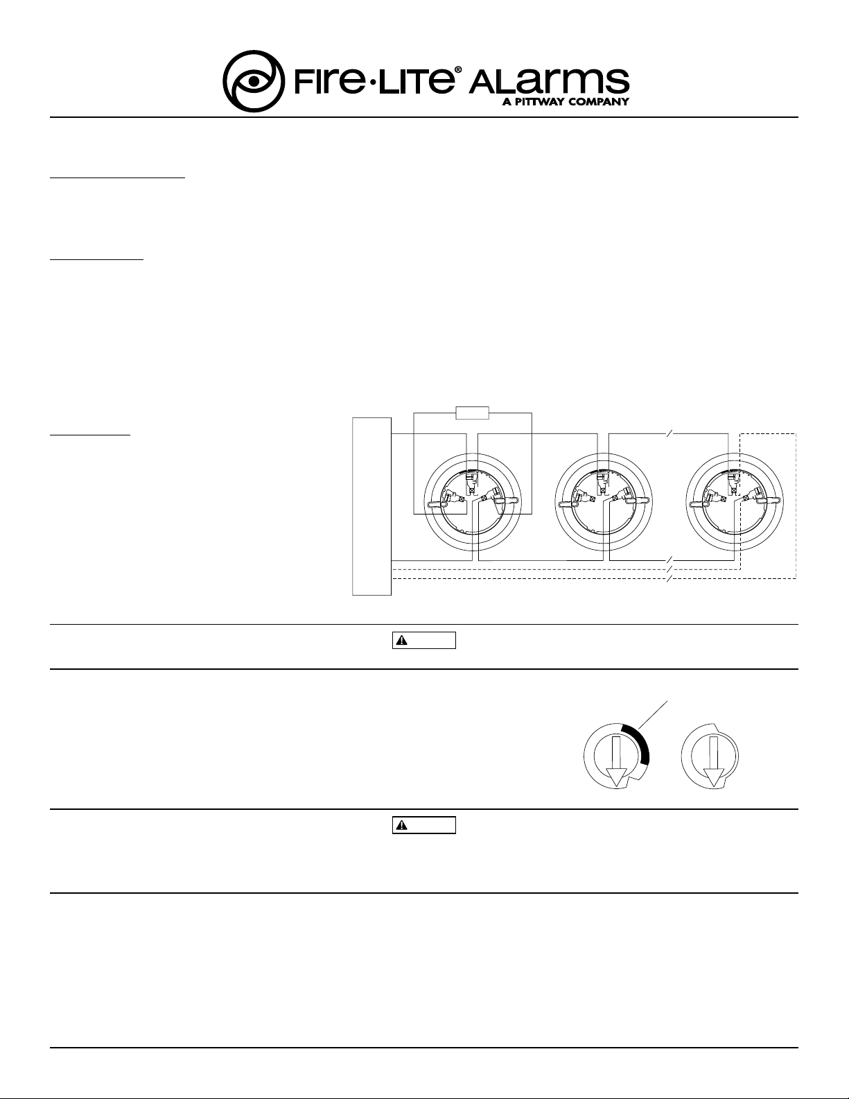
WIRING GUIDE
Refer to the installation instructions for the plug-in
base being used. As indicated in Figure 1, terminals for
power, ground, and the optional RA400Z Remote Annunciator are included in the base.
NOTE: All wiring must conform to all applicable codes,
ordinances, regulations and to the control panel
specifications.
NOTE: Verify that all sensor bases are installed and
that polarity of the wiring is correct at each base.
CONTROL PANEL
U.L. LISTED COMPATIBLE
REMOTE ANNUNCIATOR
+
-
+
+-
2
3
1
CAUTION: Do not loop wire under terminal 1 or 2.
Break wire run to provide supervision of connections.
2
3
1
CLASS A OPTIONAL WIRING
Figure 1.
2
3
1
WARNING
Disconnect loop power before installing sensors.
Before installing the sensor, please read the system wiring and installation manual, I56-407-XX. This manual includes detailed information on sensor
spacing, placement, zoning, and special applications. Copies of this manual are available from Fire•Lite.
1. Sensor Installation
a. Set the address on the sensor per job drawings.
NOTE: Some panels support extended addressing. In order to set
the sensor above address 99 on compatible systems, carefully remove the stop
on the upper rotary switch with thumb or finger as shown in Figure 2.
b. Insert the sensor into the base and rotate it clockwise until it drops into place.
c. Continue to rotate the sensor until it locks into the base.
CAUTION
Figure 2.
7
6
5
4
3
9
8
2
1
BREAKAWAY STOP
10
11
6
12
5
13
4
14
15
0
9
8
7
3
2
0
1
Dust covers are an effective way to limit the entry of dust into smoke detector sensing chambers. However, they may not completely prevent airborne
dust particles from entering the detector. Therefore, Fire•Lite recommends the removal of detectors before beginning construction or other dust producing activity.
Be sure to remove dust covers from any sensors that were left in place during construction as part of returning the system to service.
2.Tamper-Resistance
Model CP350 includes a tamper-resistant capability that prevents its removal from the bracket without the use of a tool. Refer to the base manual for
details on making use of this capability.
3. After all sensors have been installed, apply power to the system.
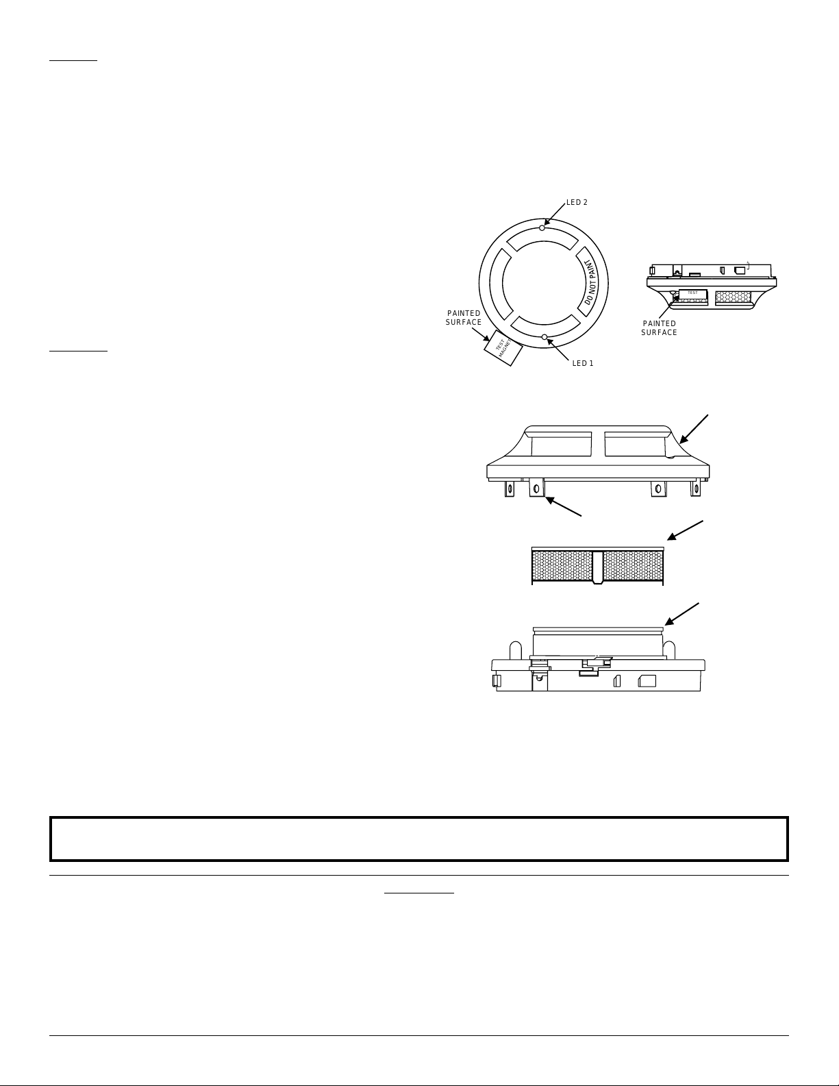
4. See Figure 3. Test the sensor by positioning a test magnet against the sensor plastic in the magnet test area. The alarm level should be recognized
at the panel and the LED controlled by communication command from the panel.
5. Reset the sensor by communication command from the panel.
F300-15-00 1 I56-036-00R
Fire•Lite, One Fire•Lite Place, Northford, CT 06472-1653, (203) 484-7161
Page 2
TESTING
Detectors must be tested after installation and following periodic maintenance. However, before testing, notify the proper authorities that the
smoke detector system is undergoing maintenance and the system will
be temporarily out of service. Disable the zone or system undergoing
maintenance to prevent unwanted alarms.
Test the sensors as follows:
A. Test Magnet (P/N M02-04-01 or M02-09-00)
1. Test the sensor by positioning the optional test magnet against the
sensor plastic in the magnet test area, as shown in Figure 3.
2. Two LEDs on the sensor are controlled by the panel to indicate sen-
sor status. Coded signals, transmitted from the panel, can cause the
LEDs to blink, latch on, or latch off. Refer to the control panel technical documentation for sensor LED operation and expected delay to
alarm.
B. Smoke Entry: Aerosol Generator (Gemini 501)
The GEMINI model 501 aerosol generator can be used for smoke
entry testing. Set the generator to represent 4%/ft to 5%/ft obscuration as described in the GEMINI 501 manual. Using the bowl shaped
applicator, apply aerosol until the panel alarms.
CLEANING
Before cleaning, notify the proper authorities that the system is undergoing maintenance and will be temporarily out of service. Disable the system to prevent unwanted alarms.
1. Remove the sensor to be cleaned from the system.
2. Remove the sensor cover, see Figure 4. Use a small standard screw-
driver to release each of the four cover removal tabs that hold the
cover in place.
3. Vacuum the outside of the screen carefully without removing it.
4. Remove the sensor screen. Pull the screen straight away from the
sensing chamber until it snaps out of place. Replacement screens
are available.
5. Use a vacuum cleaner or clean, compressed air to remove dust and
debris from the sensing chamber.
6. Reinstall or replace the sensing chamber screen by sliding the edge
without the tabs over the sensing chamber. Make sure that one of the
screen contacts touches the circuit board contact.
7. Reinstall the sensor cover. Use the LEDs to align the cover with the
sensor. Snap the cover into place.
8. When all sensors have been cleaned, restore power to the system
and test the sensor(s) as described in the TESTING section of this
manual.
LED 2
TEST
MAGNET
PAINTED
SURFACE
TEST
MAGNET
LED 1
PAINTED
SURFACE
Figure 3. Test Magnet Positioning
SENSOR
COVER
COVER REMOVAL
TABS
SENSOR
SCREEN
SENSING
CHAMBER
A78-2463-07
Figure 4. Cleaning
Please refer to insert for the Limitations of Fire Alarm Systems
This device complies with part 15 of the FCC Rules. Operation is subject to the following two conditions: (1) This device may not cause harmful interference, and (2) this
device must accept any interference received, including interference that may cause undesired operation.
Note: This equipment has been tested and found to comply with the limits for a Class B digital device, pursuant to Part 15 of the FCC Rules. These limits are designed to
provide reasonable protection against harmful interference in a residential installation. This equipment generates, uses and can radiate radio frequency energy and, if not
installed and used in accordance with the instructions, may cause harmful interference to radio communications. However, there is no guarantee that interference will not
occur in a particular installation. If this equipment does cause harmful interference to radio or television reception, which can be determined by turning the equipment off and
on, the user is encouraged to try to correct the interference by one or more of the following measures:
– Reorient or relocate the receiving antenna.
– Increase the separation between the equipment and receiver.
– Connect the equipment into an outlet on a circuit different from that to which the receiver is connected.
– Consult the dealer or an experienced radio/TV technician for help.
FCC Statement
F300-15-00 2 I56-036-00R
©2000 Fire•Lite
 Loading...