

Page 1

PN: 52265:B ECN 08-087
Distributed Audio Panel
ACC-25/50DA & ACC-25/50DAZS
Document #52265
1/30/08 Rev.
B
Page 2

Fire Alarm System Limitations
While a fire alarm system may lower insurance
rates, it is not a substitute for fire insurance!
An automatic fire alarm system–typically made up of
smoke detectors, heat detectors, manual pull stations,
audible warning devices, and a fire alarm control panel with
remote notification capability–can provide early warning of a
developing fire. Such a system, however, does not assure
protection against property damage or loss of life resulting
from a fire.
The Manufacturer recommends that smoke and/or heat
detectors be located throughout a protected premise following the recommendations of the current edition of the
National Fire Protection Association Standard 72 (NFPA 72),
manufacturer's recommendations, State and local codes,
and the recommendations contained in the Guides for
Proper Use of System Smoke Detectors, which are made
available at no charge to all installing dealers. These documents can be found at http:/www.systemsensor.com/html/
applicat.html. A study by the Federal Emergency Management Agency (an agency of the United States government)
indicated that smoke detectors may not go off in as many as
35% of all fires. While fire alarm
systems are designed to provide early warning against fire,
they do not guarantee warning or protection against fire. A
fire alarm system may not provide timely or adequate
warning, or simply may not function, for a variety of reasons:
Smoke detectors may not sense fire where smoke cannot
reach the detectors such as in chimneys, in or behind walls,
on roofs, or on the other side of closed doors. Smoke
detectors also may not sense a fire on another level or floor
of a building. A second-floor detector, for example, may not
sense a first-floor or basement fire.
Particles of combustion or "smoke" from a developing fire
may not reach the sensing chambers of smoke detectors
because:
• Barriers such as closed or partially closed doors, walls, or
chimneys may inhibit particle or smoke flow.
• Smoke particles may become "cold," stratify, and not
reach the ceiling or upper walls where detectors are
located.
• Smoke particles may be blown away from detectors by air
outlets.
• Smoke particles may be drawn into air returns before
reaching the detector.
The amount of "smoke" present may be insufficient to alarm
smoke detectors. Smoke detectors are designed to alarm
at various levels of smoke density. If such density levels are
not created by a developing fire at the location of detectors,
the detectors will not go into alarm.
Smoke detectors, even when working properly, have sensing limitations. Detectors that have photoelectronic sensing
chambers tend to detect smoldering fires better than flaming fires, which have little visible smoke. Detectors that have
ionizing-type sensing chambers tend to detect fast-flaming
fires better than smoldering fires. Because fires develop in
different ways and are often unpredictable in their growth,
neither type of detector is necessarily best and a given type
of detector may not provide adequate warning of a fire.
Smoke detectors cannot be expected to provide adequate
warning of fires caused by arson, children playing with
matches (especially in bedrooms), smoking in bed, and
violent explosions (caused by escaping gas, improper stor-
age of flammable materials, etc.).
Heat detectors do not sense particles of combustion and
alarm only when heat on their sensors increases at a
predetermined rate or reaches a predetermined level.
Rate-of-rise heat detectors may be subject to reduced
sensitivity over time. For this reason, the rate-of-rise
feature of each detector should be tested at least once
per year by a qualified fire protection specialist. Heat
detectors are designed to protect property, not life.
IMPORTANT! Smoke detectors must be installed in the
same room as the control panel and in rooms used by
the system for the connection of alarm transmission
wiring, communications, signaling, and/or power. If
detectors are not so located, a developing fire may
damage the alarm system, crippling its ability to report
a fire.
Audible warning devices such as bells may not alert
people if these devices are located on the other side of
closed or partly open doors or are located on another
floor of a building. Any warning device may fail to alert
people with a disability or those who have recently consumed drugs, alcohol or medication. Please note that:
• Strobes can, under certain circumstances, cause
seizures in people with conditions such as epilepsy.
• Studies have shown that certain people, even when
they hear a fire alarm signal, do not respond or comprehend the meaning of the signal. It is the property
owner's responsibility to conduct fire drills and other
training exercise to make people aware of fire alarm
signals and instruct them on the proper reaction to
alarm signals.
• In rare instances, the sounding of a warning device
can cause temporary or permanent hearing loss.
A fire alarm system will not operate without any
electrical power. If AC power fails, the system will
operate from standby batteries only for a specified time
and only if the batteries have been properly maintained
and replaced regularly.
Equipment used in the system may not be technically
compatible with the control. It is essential to use only
equipment listed for service with your control panel.
Telephone lines needed to transmit alarm signals from
a premise to a central monitoring station may be out of
service or temporarily disabled. For added protection
against telephone line failure, backup radio transmission systems are recommended.
The most common cause of fire alarm malfunction is
inadequate maintenance. To keep the entire fire alarm
system in excellent working order, ongoing maintenance
is required per the manufacturer's recommendations,
and UL and NFPA standards. At a minimum, the requirements of NFPA 72 shall be followed. Environments with
large amounts of dust, dirt or high air velocity require
more frequent maintenance. A maintenance agreement
should be arranged through the local manufacturer's
representative. Maintenance should be scheduled
monthly or as required by National and/or local fire codes
and should be performed by authorized professional fire
alarm installers only. Adequate written records of all
inspections should be kept.
PrecauLarge.PMD 02/26/2007
Page 3

Installation Precautions
Adherence to the following will aid in problem-free
installation with long-term reliability:
WARNING - Several different sources of power can be
connected to the fire alarm control panel. Disconnect all
sources of power before servicing. Control unit and associated equipment may be damaged by removing and/or
inserting cards, modules, or interconnecting cables while
the unit is energized. Do not attempt to install, service, or
operate this unit until this manual is read and understood.
CAUTION - System Reacceptance Test after Software
Changes. To ensure proper system operation, this product
must be tested in accordance with NFPA 72 after any
programming operation or change in site-specific software.
Reacceptance testing is required after any change,
addition or deletion of system components, or after any
modification, repair or adjustment to system hardware or
wiring.
All components, circuits, system operations, or software
functions known to be affected by a change must be 100%
tested. In addition, to ensure that other operations are not
inadvertently affected, at least 10% of initiating devices that
are not directly affected by the change, up to a maximum of
50 devices, must also be tested and proper system
operation verified.
This system meets NFPA requirements for indoor dry
operation at 0-49° C/32-120° F
93 ±2% RH (non-condensing) at 32 ±2° C/90 ±3° F.
However, the useful life of the system's standby batteries
and the electronic components may be adversely affected
by extreme temperature ranges and humidity. Therefore, it
is recommended that this system and all peripherals be
installed in an environment with a nominal room temperature of 15-27° C/60-80° F.
Verify that wire sizes are adequate for all initiating and
indicating device loops. Refer to manual Specifications
section for maximum allowable I.R. drop from the specified
device voltage.
and at a relative humidity of
Like all solid state electronic devices, this system may
operate erratically or can be damaged when subjected to
lightning-induced transients. Although no system is
completely immune from lightning transients and
interferences, proper grounding will reduce susceptibility.
Overhead or outside aerial wiring is not recommended, due
to an increased susceptibility to nearby lightning strikes.
Consult with the Technical Services Department if any
problems are anticipated or encountered.
Disconnect AC power and batteries prior to removing or
inserting circuit boards. Failure to do so can damage
circuits.
Remove all electronic assemblies prior to any drilling,
filing, reaming, or punching of the enclosure. When
possible, make all cable entries from the sides or rear.
Before making modifications, verify that they will not
interfere with battery, transformer, and printed circuit board
location.
Do not tighten screw terminals more than 9 in-lbs.
Over-tightening may damage threads, resulting in reduced
terminal contact pressure and difficulty with screw terminal
removal.
This system contains static-sensitive components.
Always ground yourself with a proper wrist strap before
handling any circuits so that static charges are removed
from the body. Use static-suppressive packaging to
protect electronic assemblies removed from the unit.
Follow the instructions in the installation, operating, and
programming manuals. These instructions must be
followed to avoid damage to the control panel and
associated equipment. FACP operation and reliability
depend upon proper installation by authorized personnel.
FCC Warning
WARNING: This equipment generates, uses, and can
radiate radio frequency energy and if not installed and
used in accordance with the instruction manual, may
cause interference to radio communications. It has
been tested and found to comply with the limits for class
A computing device pursuant to Subpart B of Part 15 of
FCC Rules, which is designed to provide reasonable
protection against such interference when operated in a
commercial environment. Operation of this equipment
in a residential area is likely to cause interference, in
which case the user will be required to correct the
interference at their own expense.
PrecauLarge.PMD 02/26/2007
Canadian Requirements
This digital apparatus does not exceed the Class A
limits for radiation noise emissions from digital
apparatus set out in the Radio Interference Regulations
of the Canadian Department of Communications.
Le present appareil numerique n'emet pas de bruits
radioelectriques depassant les limites applicables aux
appareils numeriques de la classe A prescrites dans le
Reglement sur le brouillage radioelectrique edicte par
le ministere des Communications du Canada.
Page 4

Table of Contents
CHAPTER 1: Product Description .....................................................................................................................10
Product Features ............................................................................................................................................11
Specifications ................................................................................................................................................15
Indicators ......................................................................................................................................................17
LEDs Located on Main Circuit Board: ..................................................................................................17
ACC-ZPM Zone Page Module (ACC-25/50DAZS Only) .....................................................................17
ACC-AAM25 Audio Amplifier Module ................................................................................................ 17
Circuits .......................................................................................................................................................... 18
Components ..................................................................................................................................................19
Optional Modules .........................................................................................................................................20
Getting Started .............................................................................................................................................. 21
ACC-25/50 With ACC-25/50DA(s), System Requiring Greater Than 50 Watts of Audio Power ......... 21
ACC-25/50ZS Wit h ACC- 25/50DAZS, System Requiring Greater Than 50 Watts of Audio Power .... 21
CHAPTER 2: Field Programming ...................................................................................................................... 22
S1 DIP Switch Settings on Distributed Audio Motherboard ......................................................................... 23
S2 DIP Switch Settings on Distributed Audio Motherboard ......................................................................... 24
S3 - Battery Charger Switch on Distributed Audio Motherboard ................................................................. 24
ACC-ZPM Zone Page Module ......................................................................................................................25
S1 DIP Switch Settings on ACC-ZPM .................................................................................................. 25
S2 and S3 Addressing Rotary Switches .................................................................................................25
ACC-ZSM Zone Splitter Module ..................................................................................................................26
Switch SW1 on ACC-AAM25 Audio Amplifier Module .............................................................................26
Switch SW1 Settings on Optional FC-MGM Module .................................................................................. 26
CHAPTER 3: Installation ....................................................................................................................................28
Mounting .......................................................................................................................................................28
Backbox Installation .....................................................................................................................................28
Transformer Installation .........................................................................................................................31
Operating Power ...........................................................................................................................................32
Auxiliary DC Power Output Connections ..................................................................................................... 33
Input Circuits .................................................................................................................................................33
Master Command Bus ............................................................................................................................ 33
CMD Input Circuits ............................................................................................................................... 34
Trouble Contact Input ............................................................................................................................34
Output Circuits .............................................................................................................................................. 35
Trouble Relay - TB1 ..............................................................................................................................35
AC Power Loss Relay - TB11 ................................................................................................................35
Notification Appliance Circuit (Speakers) ............................................................................................. 35
ACC-ZPM Zone Page Module - Zone System Serial Link ....................................................................36
ACC-ZSM Zone Splitter Module .......................................................................................................... 37
UL Power-limited Wiring Requirements ...................................................................................................... 38
Installation of Option Modules .....................................................................................................................39
Audio Amplifier Module [ACC-AAM25] .............................................................................................39
70.7 V
Transformer Module (FC-XRM70) ......................................................................................40
RMS
FC-MGM Message Generator Module ..................................................................................................41
FC-LPS Local Playback Speaker Module ..............................................................................................42
CHAPTER 4: Operating Instructions ................................................................................................................ 43
Message Recording .......................................................................................................................................43
Record Push Button (on optional FC-MGM Module) ...........................................................................43
Playback Button .....................................................................................................................................44
LEDs on Main Circuit Board .................................................................................................................45
LEDs on Optional Message Generator Module (FC-MGM) ................................................................. 45
LEDs on Audio Amplifier Module ........................................................................................................ 45
4
ACC-25/50DA 52265:B 1/30/08
Page 5

Table of Contents
LEDs on ACC-ZPM (ACC-25/50DAZS Only) ..................................................................................... 45
Operation ......................................................................................................................................................46
Fire Alarm .............................................................................................................................................. 46
Fire Alarm Restoral ...............................................................................................................................46
General Page Using Optional Remote Microphone (ACC-25/50DA Only) .......................................... 46
Emergency Page Using Optional Remote Microphone (ACC-25/50DA Only) ..................................... 46
Trouble Condition Response ..................................................................................................................46
Trouble Condition Restoral ....................................................................................................................48
CHAPTER 5: Application Examples .................................................................................................................. 49
ACC-25/50 & ACC-25/50DA Step-by-Step Install/Setup ............................................................................ 49
ACC-25/50ZS & ACC-25/50DAZS Step-by-Step Install/Setup ...................................................................49
One Speaker Circuit ...................................................................................................................................... 50
Single Channel ....................................................................................................................................... 50
Dual Channel ......................................................................................................................................... 51
One Speaker Circuit With Backup ................................................................................................................ 52
Single Channel ....................................................................................................................................... 52
Dual Channel ......................................................................................................................................... 53
Two Speaker Circuits .................................................................................................................................... 54
Single Channel ....................................................................................................................................... 54
Dual Channel ......................................................................................................................................... 55
ACC-25/50DA High-Power, Multi-floor Application .................................................................................. 56
ACC-25/50 Series and ACC-25/50DA Installation ...................................................................................... 57
16 Theater Cineplex Utilizing ACC-25/50ZS ............................................................................................... 59
Audio Command Center 24 Zone System .....................................................................................................60
CHAPTER 6: Power Supply Calculations ......................................................................................................... 61
Overview .......................................................................................................................................................61
Calculating the AC Branch Circuit ............................................................................................................... 61
Calculating the System Current Draw ...........................................................................................................61
Overview ................................................................................................................................................ 61
How to use Table 6-2 to calculate system current draws ...................................................................... 62
Calculating the Battery Size .......................................................................................................................... 63
NFPA Battery Requirements .................................................................................................................. 63
Selecting and Locating Batteries ........................................................................................................... 63
Digital Voice Messages ...........................................................................................................................................64
Addressable Module Connections .........................................................................................................................65
Wiring Requirements .............................................................................................................................................66
ACC-25/50DA 52265:B 1/30/08 5
Page 6

Notes
6
ACC-25/50DA 52265:B 1/30/08
Page 7

This audio panel has been designed to comply with standards set forth by the following regulatory agencies:
• Underwriters Laboratories Standard UL 864
• NFPA 72 National Fire Alarm Code
Before proceeding, the installer should be familiar with the following documents.
NFPA Standards
This Audio Distribution Panel complies with the following NFPA Standards:
NFPA 72 National Fire Alarm Code
Note: Audible signal appliances used in public mode applications, are required to have minimum
sound levels of 75 dBA at 10 feet (3 meters) and a maximum level of 120 dBA at the minimum hearing distance from the audible appliance.
To ensure that the appliance is clearly heard, the audible appliance sound level must be at least 15
dBA above the average ambient sound level or 5 dBA above the maximum sound level with a duration of at least 60 seconds, depending on which level is greater, with the sound level being measured 5
feet (1.5 meters) above the floor.
Underwriters Laboratories Documents:
UL 38 Manually Actuated Signaling Boxes
UL 217 Smoke Detectors, Single and Multiple Station
UL 228 Door Closers–Holders for Fire Protective Signaling Systems
UL 268 Smoke Detectors for Fire Protective Signaling Systems
UL 268A Smoke Detectors for Duct Applications
UL 346 Waterflow Indicators for Fire Protective Signaling Systems
UL 464 Audible Signaling Appliances
UL 521 Heat Detectors for Fire Protective Signaling Systems
UL 864 Standard for Control Units for Fire Protective Signaling Systems
UL 1481 Power Supplies for Fire Protective Signaling Systems
UL 1638 Visual Signaling Appliances
UL 1711 Amplifiers for Fire Protective Signaling Systems
UL 1971 Signaling Devices for Hearing Impaired
Other:
NEC Article 250 Grounding
NEC Article 300 Wiring Methods
NEC Article 760 Fire Protective Signaling Systems
Applicable Local and State Building Codes
Requirements of the Local Authority Having Jurisdiction (LAHJ)
Fire•Lite Documents
Fire•Lite Device Compatibility Document Document #15384
FCPS-24F(E) Field Charger/Power Supply Document #50079
FCPS-2404 Field Charger/Power Supply Document #51486
FCPS-24FS Field Charger/Power Supply Document #51883
MS-9200(C)/E Technical Manual Document #51003
MS-9200UDTechnical Manual Document #51906
MS-9600 Technical Manual Document #51335
MS-5210UDTechnical Manual Document #50193
ACC-25/50 Series Manual Document #51889
SLC Wiring Manual (with addressable devices)Document #51309
This product has been certified to comply with the requirements in the Standard for Control Units and Accessories for Fire Alarm Systems, UL
864, 9th Edition. Operation of this product with products not tested for UL 864, 9th Edition has not been evaluated. Such operation requires the
approval of the local Authority Having Jurisdiction (AHJ).
ACC-25/50DA 52265:B 1/30/08 7
Page 8
25W Speaker Circuit
25W Speaker Circuit
25W Speaker Circuit
25W Speaker Circuit
To Additional ACC-25/50DA Panels
ACC-25/50DA
Audio Riser
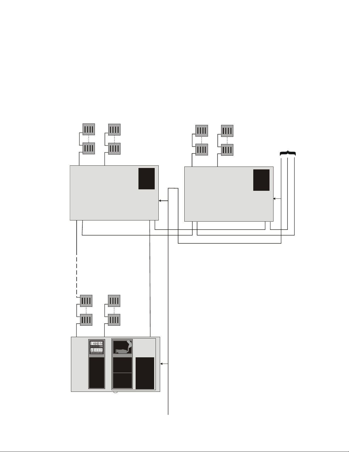
Audio Command Center Distributed System
Audio Riser
25W Speaker Circuit
25W Speaker Circuit
Master Command Bus
ACC-25/50DA
FACP Control
Audio Riser
Master Command Bus
Master Command Bus
Audio Riser
FACP Control
ACC-25/50
CMD inputs on the ACC-25/50 and ACC-25/50DA(s)
1. The F ACP can automatically control the audio system via the
FACP Control
8 ACC-25/50DA 52265:B 1/30/08
2. The Audio Riser connects the audio output of the ACC-25/50
to each of the ACC-25/50DA(s).
the ACC-25/50 to the ACC-25/50DA(s).
configuration.
3. The Master Command Bus provides an All-Call trigger from
4. Maximum of 25 Distributed Audio panels may be used in this
accdadistsys.CDR
Page 9
Speaker Circuit #9
Speaker Circuit #16
Speaker Circuit #17
Speaker Circuit #24
Audio Riser
Up to 24 Zones @ 150W (max.)
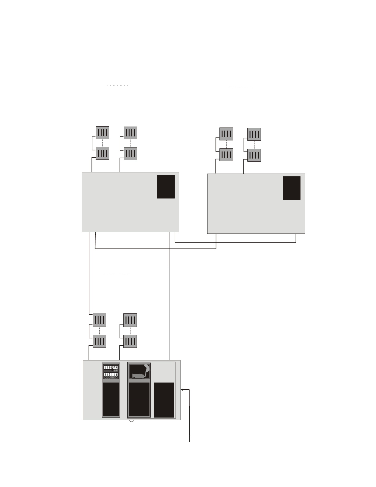
Audio Command Center Zone System
Audio Riser
Speaker Circuit #1
ACC-25/50DA
Speaker Circuit #8
ACC-25/50DA
ACC Control Serial Link (RS-485)
ACC Control Serial Link (RS-485)
ACC-25/50
Zone Split Configuration
CMD inputs on the ACC-25/50ZS.
50ZS to each of the ACC-25/50DAZS(s) to distribute alarm
or paging audio.
the routing of the alarm or paging audio.
survivability from attack by fire requirements in National
Fire Alarm Code, NFPA 72.
1. The FACP controls the audio system via the ACS Link or
2. The Audio Riser connects the audio output of the ACC-25/
Automatic Control via the
ACS Link or CMD Input
ACC-25/50DA 52265:B 1/30/08 9
3. The ACC-25/50ZS uses the Control Serial Link to control
4. Riser conductors must be installed in accordance with the
accdazsdistsys.CDR
Page 10

Product Description
CHAPTER 1 Pr oduct Description
The AUDIO•COMMAND•CENTER•25/50DA Distributed Panel (ACC-25/50DA) and AUDIO•COMMAND•CENTER•25/50DAZS Zone System Distributed Panel (ACC-25/50DAZS) are single channel, 25 watt, 25 V
gency voice evacuation panels which are designed to interface directly to the AUDIO•COMMAND•CENTER•25/50
(ACC-25/50) Series audio panels. The ACC-25/50DA Series, which supports up to eight speaker circuits, can be
used to distribute voice evacuation audio over a building’s speaker system. The audio riser input provides automatic
gain control (AGC) which compensates for any audio signal loss due to circuit loading or cable length, ensuring that
a full output signal is delivered to the speakers. An optional FC-MGM message generator is available with standard
pre-recorded message or programmable message capability (up to sixty seconds). An integral power supply with battery charger supplies operational power. An ACC-AAM25 audio amplifier is provided standard with each base unit.
An optional second ACC-AAM25 amplifier is also available for backup purposes or to provide an additional 25 watt
speaker circuit. Optional 70 V
conversion modules are also available for installations where 70 V
RMS
to be installed or already exist. The modular design allows for ease-of-serviceability.
The ACC-25/50DA can be automatically activated by the five CMD inputs from an FACP. The ACC-25/50DAZS
can be automatically activated via the Zone System serial communications link from the ACC-25/50ZS.
, emer-
RMS
speakers are
RMS
T wo Command Input Circuits can be independently field programmed for activation by an FACP Notification Appliance Circuit reverse polarity or by closure of a supervised normally open contact and three Command Input Circuits
activate on contact closure. CMD 1 and CMD 2 provide terminals for NAC input and output to allow instal lati on of
the audio panel anywhere along the NAC circuit being used to activate it.
The ACC-25/50DAZS includes an ACC-ZPM Zone Page Module and an ACC-ZSM Zone Splitter Module. These
modules provide up to eight speaker circuits that may be manually or automatically activated. Significant technological enhancements set the ACC-25/50DA Series apart from other voice panels. These enhancements include full
supervision in both active (alarm or music) and standby conditions.
Note: Music cannot be used for ACC-25/50DAZS.
Supervision is provided for:
amplifier outputs
field wiring (shorts and opens)
optional message generator (FC-MGM)
all tone generators
optional remote microphone
If the audio riser input fails, the distributed audio panel can be programmed to switch to the built-in tone generator or
optional FC-MGM Message Generator. If the FC-MGM fails or is not installed, the tone generators on the main
circuit board can be automatically switched in as backups.
Power is fed independently
to each amplifier so that a short circuit in one amplifier will not shut down the other. Full
output power of 25 watts per amplifier is generated while in a low battery condition. Power is not diminished when
the optional 70 V
transformer module is installed. Audio is amplified utilizing modern integrated circuits as
RMS
opposed to transformer technology. This provides for very low signal distortion for crystal clear audio.
Primary applications for the audio panels include structures such as restaurants, schools, auditoriums, places of
worship, buildings with occupancies over 50, etc. The ACC-25/50DA Distributed Audio Series is designed to
interface directly to addressable or conventional fire alarm control panels or with the ACC-25/50 series audio control
panels to distribute audio in systems that require more than 50 watts.
10
ACC-25/50DA 52265:B 1/30/08
Page 11

Product Features
1.1 Product Features
• 25 watts of 25 V
audio power (expandable to 50 watts) per panel
RMS
• Automatic gain control (AGC) circuit ensures an unattenuated audio signal on the audio riser input
• Optional 70.7 V
conversion module available for each amplifier (note that speaker wiring continues to be
RMS
supervised in standby, alarm and when background music is playing with this option module installed)
• Modular design for maximum system flexibility
• Unobstructed module access and removable terminal blocks for ease of servicing and module replacement
• Designed to allow easy system expansion
• Five Command Input Circuits:
CMD1 and CMD2 are field selectable to be activated from 12 or 24 VDC Notification Appliance
Circuits (reverse polarity) or contact closures
CMD3, CMD4 and CMD5 are activated by contact closures
• Speaker Circuits
single Style Y or Z speaker circuit (one ACC-AAM25 Audio Amplifier provided with base unit)
two Style Y or Style Z speaker circuits (with optional second ACC-AAM25 Audio Amplifier instal led)
eight Style Y or four Style Z speaker circuits using ACC-ZSM Zone Splitter Module
• ACC-25/50DAZS can be controlled by the ACC-25/50ZS via the Zone System serial link (EIA-485) to the
ACC-ZPM.
• Optional FC-MGM Message Generator Module with standard, prerecorded message:
“May I have your attention please. May I have your attention please. The signal you have just heard
indicates a report of a fire in this building. Please proceed to the nearest exit and leave the building.
Do not reenter the building unless directed to do so by the proper authorities.”
• Field selectable message capability and custom message field recording capability using optional FC-MGM
module’s audio input RCA jack or mini Audio jack for connection to a personal computer
• Record/playback control switches on optional FC-MGM
• One 60-second, two 30-second, three 20-second or four 15-second custom messages on optional FC-MGM
• Integral tone generators field selectable for steady, slow-whoop, high-low or chime tones
• Powered by integral AC power supply or batteries during AC fail
• T wo Form-C trouble relays:
System Trouble Relay - TB1
AC Power Loss Relay - TB11
• 35 mA Special Application auxiliary power output for addressable modules (when interfaced with the
Fire•Lite MS-9200(E), MS-9200UD or MS-9600 FACP or equivalent) and End-of-Line power supervision
relays
• Optional FC-RM Remote Microphone (includes cabinet and FC-MIM Microphone Interface Module). Refer
to the FC-RM Product Installation Document #51247 for additional information
• Optional local playback speaker (FC-LPS) for use with optional FC-MGM
• System Status LEDs (refer to Section 1.3 "Indicators" on page 17)
ACC-25/50DA 52265:B 1/30/08 11
Page 12
Product Features
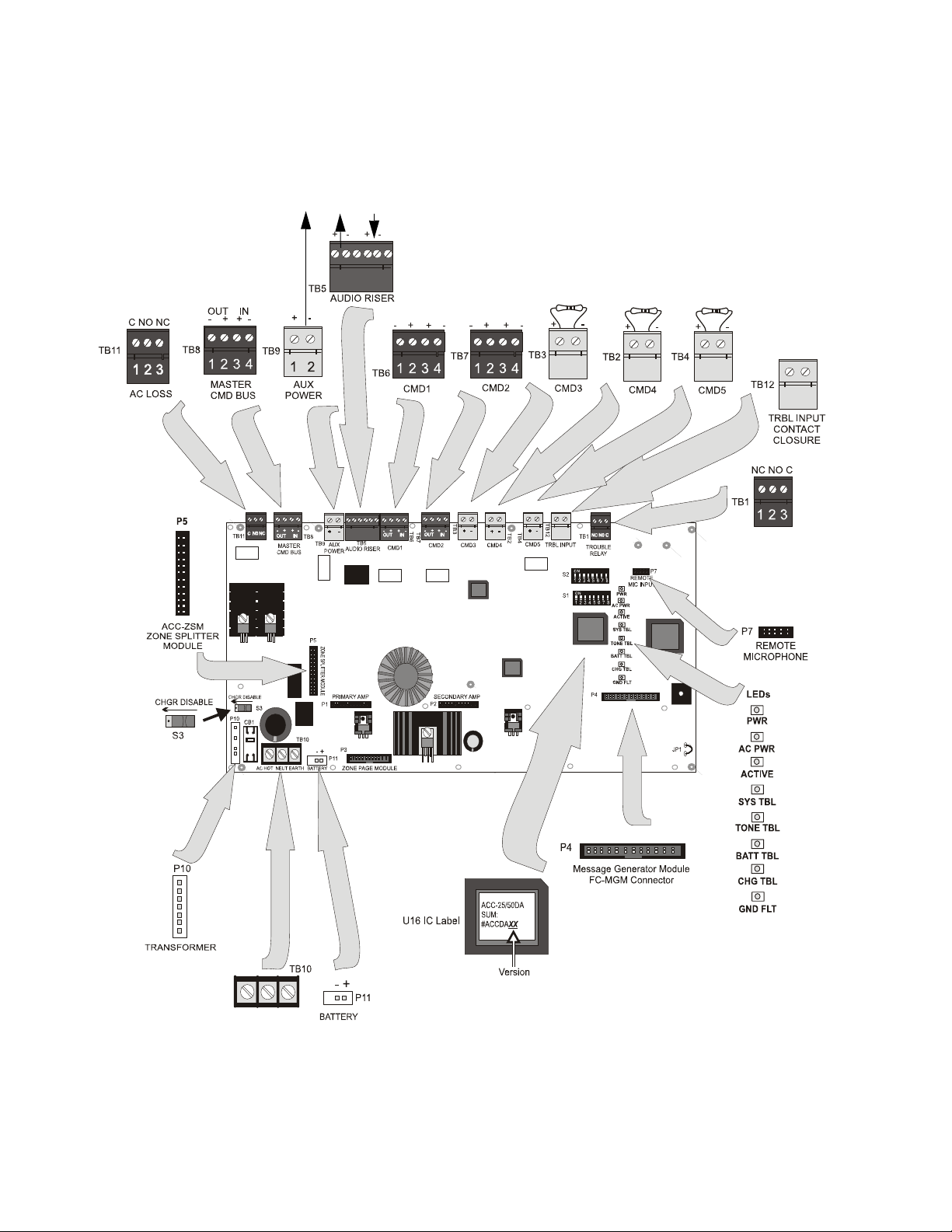
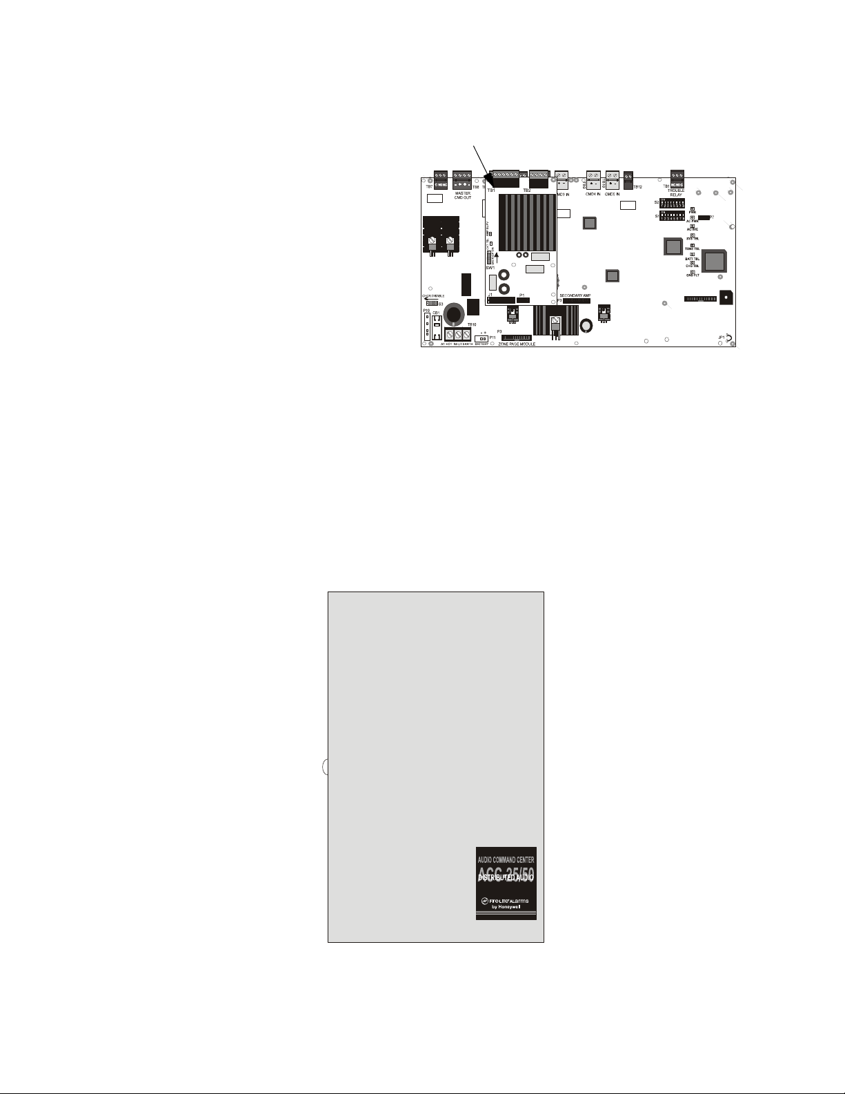
FIGURE 1-1:Distributed Audio Main Board
Specific
Application
Power
35 mA
nonsupervised
power-limited
Form-C AC
Loss Relay
nonsupervised
Input Triggersupervised
(activation by
reverse polarityactive polarity
shown)
use ELR specified
for triggering
source
nonsupervised
OUT IN
shield
shield
All CMD inputs and Trouble Contact Closure are supervised
and power-limited and require a 4.7KΩ ELR, P/N: 27072
CMD1 & CMD 2 Input
Trigger by contact
closure or NAC reverse
polarity - alarm polarity
shown
OUT IN
OUT IN
CMD3, CMD4 & CMD5 Input
Trigger by contact closure
alarm polarity shown (inputs only)
1 2
1 2
1 2
for monitoring
trouble contacts of
an external device
such as charger or
power supply
1 2
S3 Charger Enable/
Disable Switch
(shown in charger
enabled position)
Connector for
Transformer
Form-C Trouble Relay
(nonsupervised)
FC-MIM
AC25DAMNT1.CDR
12
HOT
(supervised,
nonpower-limited)
EARTH
NEUTRAL
AC Power Only (supervised,
nonpower-limited)
Refer to AC Power in Section
1.2 "Specifications" on page 15
ACC-25/50DA 52265:B 1/30/08
Battery
Page 13
Product Features
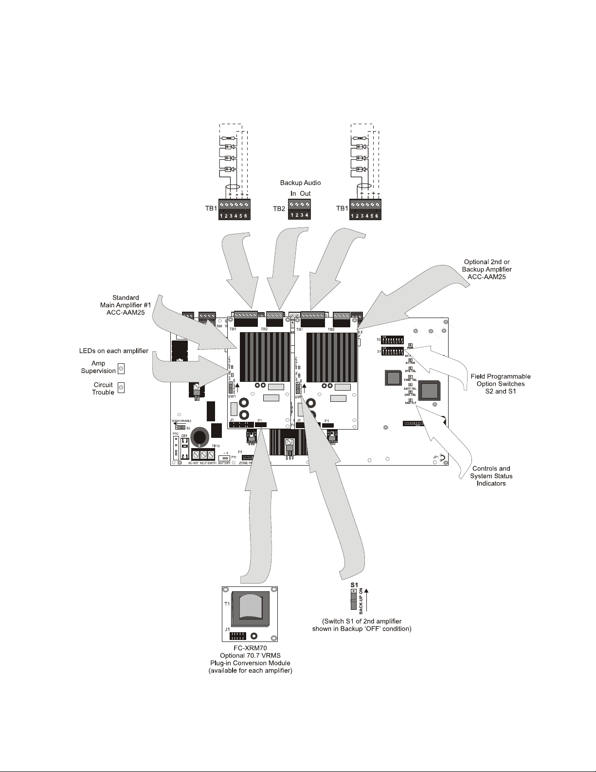
FIGURE 1-2:
Distributed Audio Board With Amplifiers
CAUTION: Match proper polarity connections to field wiring and
speakers. Polarity shown is in the standby and alarm conditions.
Speaker Circuits are supervised
and power-limited
ELR Resistor required only for
Style Y (Class B) circuits.
4.75 KΩ, 1 watt P/N: 75470
+ - + -
ACC-25/50DA 52265:B 1/30/08 13
AC25DAMNT2.CDR
Page 14
Product Features
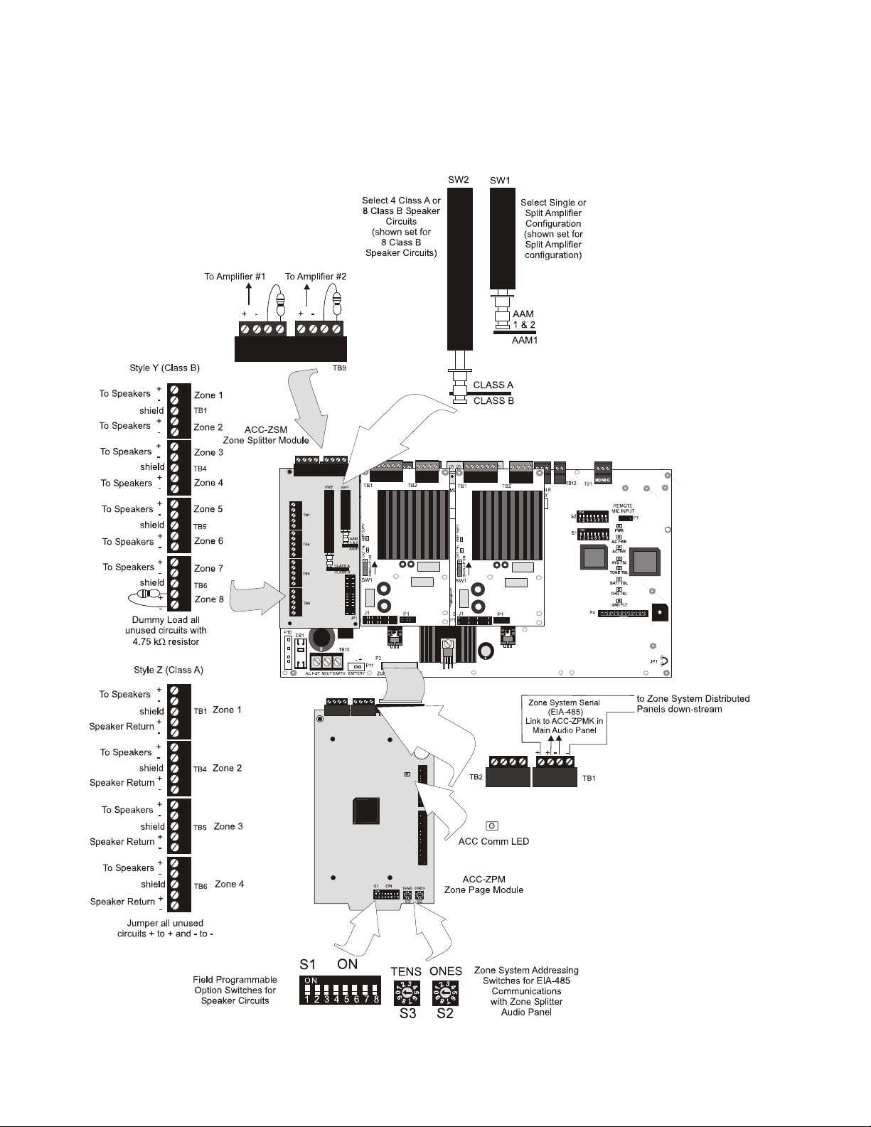
ACC-ZSM and ACC-ZPM Modules for Distributed Audio with Zone Splitter Feature Only
FIGURE 1-3:Distributed Audio Board With ACC-ZPM & ACC-ZSM Modules
Circuits are supervised and
power-limited
ELRs 4.75KΩ P/N: 27589
Speaker Circuits are
supervised and power-limited
5
4
3
2
1
5
4
3
2
1
5
4
3
2
1
5
4
3
2
1
5
4
3
2
1
5
4
3
2
1
5
4
3
2
1
5
4
3
2
1
1 2 3 4 1 2 3 4
1 2 3 4
AC25DAZSMNT.CDR
(supervised)
1 2 3 4
14
ACC-25/50DA 52265:B 1/30/08
Page 15

Specifications
1.2 Specifications
AC Power - TB10
ACC-25/50DA(ZS):120 VAC, 50/60 Hz, 2.0 amp.
Supervised, nonpower-limited circuit
Wire size: minimum #14 AWG with 600 V insulation.
AC Loss Relay - TB11
Operation: normally energized fail-safe relay transfers on AC power loss for independent monitoring by DACT.
AC Loss relay contact rating: 2.0 amps @ 30 VDC (resistive), 0.6 amps @ 30 VAC (resistive)
Nonsupervised circuit
Battery (lead acid only) - P11
Maximum Charging Circuit: Normal Flat Charge - 27.6V @ 0.800 amp
Maximum Charger Capacity: 18 Amp Hour battery (cabinet holds maximum 18 Amp Hour Battery.)
Supervised, nonpower-limited circuit
Command Input Circuits (alarm polarities shown)
• CMD1 - TB6 Terminals 3(+) & 4(-) are input terminals and Terminals 1(-) and 2(+) are output terminals
which provide feed through of the NAC circuits to NAC devices down stream
• CMD2 - TB7 Terminals 3(+) & 4(-) are input terminals and Terminals 1(-) and 2(+) are output terminals
which provide feed through of the NAC circuits to NAC devices down stream
• CMD3 - TB2 Terminals 1(+) & 2(-) are input terminals for contact closure only
• CMD4 - TB3 Terminals 1(+) & 2(-) are input terminals for contact closure only
• CMD5 - TB4 Terminals 1(+) & 2(-) are input terminals for contact closure only
Operation: CMD1 & CMD2 circuits are independently field programmable to activate amplifiers on NAC polarity reversal or contact-closure. IMPORTANT! When CMD1 and CMD2 are configured for reverse polarity, the
NAC cannot be Coded.
CMD3, CMD4 and CMD5 are fixed to activate on contact closure only
Power-limited and supervised circuitry
Normal Operating Voltage: 10.5 VDC - 29 VDC Maximum Voltage: 29 VDC
NAC Reverse Polarity Current (requires End-of-Line Resistor from NAC): 1.6 mA maximum.
Contact Closure Operation Current (requires 4.7K, ½ watt End-of-Line Resistor P/N 27072): 6.6 mA maximum
Maximum Wiring Impedance CMD1 - CMD5 (Contact Closure Operation): 200Ω
Maximum Input Impedance:
• CMD1 & CMD2 (Reverse Polarity Operation): 20KΩ
• CMD1 - CMD5 (Contact Closure Operation): 3.4KΩ
Audio Amplifier Module - Standard ACC-AAM25 Amplifier plugs into P1 of main circuit board, optional
ACC-AAM25 Amplifier plugs into P2 of main circuit board
Backup Audio In - TB2, Terminals 1(+) & 2(-) [Out Terminals 3(+) & 4(-)] on Amplifier Module
Operation: When TB2 is wired between the two amplifiers of a panel, the optional amplifier provides backup to
the standard amplifier. Switch S1 on the backup amplifier must be 'ON' and jumpers placed from backup amplifier TB2 Terminal 3 to standard amplifier TB2 Terminal 1 and from backup amplifier TB2 Terminal 4 to standard
amplifier TB2 Terminal 2. Refer to Section 5.4 "One Speaker Circuit With Backup" on page 52, for additional
information.
ACC-25/50DA 52265:B 1/30/08 15
Page 16

Specifications
Speaker Circuit - TB1 Terminals 3(+) & 4(-) Style Y, 3(+), 4(-), 5(+) & 6(-) Style Z, 1 & 2 Shield (Standby and
Alarm Polarity Shown) on Amplifier Module
Power-limited, supervised circuitry
Operation: Circuit can be wired Style Y or Style Z
Normal Operating Voltage: 25 V
(70.7 V
@ 350 mA max. with maximum Load Impedance of 200Ω operation possible by plugging
RMS
@ 1 amp max. and maximum Load Impedance of 25Ω
RMS
optional FC-XRM70 conversion module into P1 of audio amplifier).
Circuit wiring is supervised during standby, alarm and when background music is playing
Output Power: 25 watts (20 watts when background music is employed). Frequency Range: 400Hz - 4,000Hz
Maximum total capacitance for each AAM-25/50: 250 uF.
End-of-Line Resistor required for Style Y circuit: 4.75 KΩ, 1 watt (P/N: 75470)
ACC-ZSM Zone Splitter Module and ACC-ZPM Zone Page Module
Power-limited circuitry
Operation: Circuits on ACC-ZSM can be wired as eight Style Y or four Style Z
Normal Operating Voltage for Speaker Circuits: 25 V
(70.0 V
@ 350 mA max. with maximum Load Impedance of 200Ω operation possible by plugging
RMS
@1 amp Max. and maximum Load Impedance of 25Ω
RMS
optional FC-XRM70 conversion module into P1 of audio amplifier).
Speaker circuit wiring is supervised during standby and alarm. (Note that background music is not permitted
in
Zone Splitter configuration since open-circuit fault detection is not possible)
Output Power: 25 watts total. Frequency Range: 400Hz - 4,000Hz
Maximum total capacitance for ACC-AAM25: 250 µF. (Note that the total
capacitance for the ACC-ZSM
speaker outputs must not exceed the maximum of 250 µF).
End-of-Line Resistor required for Style Y (Class B) speaker circuit: 4.75 KΩ, 1 watt (P/N: 75470)
TB1 on ACC-ZPM: ACS (EIA-485) electrically isolated link to FACP provides programmed speaker control
Master CMD Bus - TB8 Terminals 1(-), 2(+), 3(+) & 4(-) (active polarity shown)
Provides reverse polarity trigger input from ACC-25/50 Series Master Command Bus Output.
Supervised and power-limited circuitry
Normal Operating Voltage: 24 VDC regulated, filtered. Maximum Voltage: 25.4 VDC
Reverse Polarity Current: 125 mA maximum.
Standby Voltage: -5 VDC. Short Circuit Current: 0.5 mA. Maximum Load Resistance: 200 ohms.
Wiring connections to Master CMD Bus Circuit:
End-of-Line Resistor required for Class B using Terminals 2(+) & 1(-): 4.7 KΩ, ½ watt (P/N: 27072)
Class A (no End-of-Line Resistor) requires the wiring of Terminal 2(+) and Terminal 1(-) to next
Distributed Audio Panel
Special Application Power (Aux. Power) - TB9 Terminals 1(+) & 2(-)
Up to 35 mA @ 24 VDC special application power is available for powering addressable modules and associated
End-of-Line power supervision relays. Output is unsupervised.
Power-limited circuitry. Refer to the Device Compatibility Document for a list of compatible devices.
Form-C Trouble Relay - TB1
Normally energized fail-safe relay transfers its contacts on any panel trouble condition.
TB1 Form-C relay contact rating: 2.0 amps @ 30 VDC (resistive), 0.6 amps @ 30 VAC (resistive).
16
ACC-25/50DA 52265:B 1/30/08
Page 17

Indicators
External Audio Inputs - Optional FC-MGM Message Generator Module on P4
• RCA Audio Jack Input (female connector)
Input Impedance: 30KΩ maximum
Input Voltage: 700 mV
maximum
RMS
Input Current: 1 mA maximum @ 700 mV
Requires preamplifier output. Mates to an RCA phono 'plug' - 3mm diameter, 10mm length, 9mm
shell diameter.
• 3.5 mm PC Audio Jack Input (female connector)
Input Impedance: 150KΩ maximum
Input Voltage: 700 mV
maximum
RMS
Input Current: 1 mA maximum @ 700 mV
Requires preamplifier output
Interfaces to personal computer line output or headset output (Note: Some laptop personal computers
only provide an audio output for headphones. It may be necessary to adjust the headphone output
level for proper recording of voice messages.)
• Microphone Connector for optional standard microphone P/N: FC-MICROPHONE
FC-MIM Microphone Interface Module (Optional) - P7 Connector
Connector P7 provides a connection for:
• the optional FC-MIM Microphone Interface Module which is used to connect the FC-RM Remote Micro-
phone Module to provide remote microphone paging capabilities.
Audio Riser - TB5
Magnetically isolated input utilizes signals up to 70.7 V
with a frequency range of 400 Hz to 4 KHz.
RMS
Note: For ACC-25/50DA Only - If background music is enabled, the maximum input signal to the riser:
• with a 20 watt speaker load per amplifier cannot exceed 25 V
• with a 25 watt speaker load per amplifier cannot exceed 20 V
RMS
RMS
Trouble Contact Input - TB12
Non-supervised, non-isolated trouble input that can be used by chargers, power supplies, etc.
Contact Closure Operation Current: 1.2 mA maximum
Standby Current: n/a
1.3 Indicators
1.3.1 LEDs Located on Main Circuit Board:
• Power ON (green)
• AC Power (green)
• Active (green)
• System Trouble (yellow)
• Tone Generator Trouble (yellow)
• Battery Trouble (yellow)
• Charger Trouble (yellow)
• Ground Fault (yellow)
1.3.2 ACC-ZPM Zone Page Module (ACC-25/50DAZS Only)
• ACC Comm (green LED) - indicates Communication is active on the serial link to the ACC-25/50ZS. Off
indicates no communication.
1.3.3 ACC-AAM25 Audio Amplifier Module
• Circuit Trouble (yellow) - Amplifier module
• Amplifier Supervision (green) - Amplifier module
ACC-25/50DA 52265:B 1/30/08 17
Page 18

Circuits
1.4 Circuits
Input Circuits - CMD1, CMD2, CMD3, CMD4 & CMD5
• Input circuits CMD1 and CMD2 are independently field programmable to accept Notification Appliance Cir-
cuits or normally open contacts. (IMPORTANT! When CMD1 and CMD2 are configured for reverse polarity, the NAC cannot be Coded). Terminals are provided to allow feed-through of the NACs, allowing
placement of the ACC-25/50 Series anywhere along a Notification Appliance Circuit. A trouble on the ACC25/50DA will cause relay contacts at the out terminals of CMD1 to open, causing an NAC circuit trouble at
the FACP. Note: The ACC-25/50DA will not open the out terminals while in alarm. Monitoring ACC-25/
50DA troubles while in alarm requires use of independent trouble relay at TB1.
• Programming CMD1 and/or CMD2 for activation on contact closure will allow activation of the amplifiers on
a normally open contact transfer to the closed condition. Contact wiring is supervised for open conditions. A
short will cause amplifier activation (contact closure).
• Input circuits CMD3, CMD4 and CMD5 will only activate on contact closure which will allow activation of
the amplifiers on a normally open contact transfer to the closed condition. Contact wiring is supervised for
open conditions.
• Contact Closure Trouble Input is used for identification of troubles on an optional external power supply or
charger.
Audio Input Jacks (located on optional FC-MGM Message Generator Module)
• RCA Jack provides convenient connection to an audio source such as a tape player for recording a new digital
message.
• PC Jack provides convenient connection to an audio source such as a personal computer for recording a new
digital message. The jack allows vertical plug-in of a standard mini-jack cable.
• Microphone Jack provides connection for a standard compatible microphone.
Output Circuits
• Specific Application Power Output, 35 mA @ 24 VDC.
• Main circuit provides a 24 Volt Battery Charger (up to 18 AH batteries) @ 800 mA maximum .
Master Command Bus
• Normal Operating Voltage: 24 VDC regulated, fil tered . Reverse Polarity Current 125 mA maximum.
• Control bus from the ACC-25/50 Series or other UL listed compatible audio products.
Notification Appliance Circuit
• One NAC Speaker Circuit Style Y or Style Z with each ACC-AAM25 amplif ier module.
• Four NAC Speaker Circuits Style Z or eight Style Y with ACC-ZSM.
Relays
• One Form-C Trouble Relay. TB1 Contacts are rated 2.0 amps @ 30 VDC (resistive) and 0.6 amps @ 30 VAC
(resistive).
• One Form-C AC Loss Relay. TB11 Contacts are rated 2.0 amps @ 30 VDC (resistive) and 0.6 amps 30 VAC
(resistive).
FC-MIM Microphone Interface Module
• Connector P7 provides a connection for the optional FC-MIM Microphone Interface Module which is used to
connect the FC-RM Remote Microphone Module to provide remote microphone paging capabilities (refer to
Remote Microphone Installation document #51247).
ACC-ZPM Zone Page Module
• Connector P3 provides a connection for the ACC-ZPM Zone Page Module which is used to annunciate and
control the selection of speaker circuits. Refer to Section 3.6.4 "ACC-ZPM Zone Page Module - Zone System
Serial Link" on page 36.
Local Speaker
• The removable local speaker P/N: FC-LPS can be mounted on the ACC-25/50DA main circuit board and connected to the FC-MGM module, to be used for reviewing the digital message without broadcasting over the
system speakers. The local speaker must be installed to take adva ntage of the playback feature. The FC-LPS
cannot be permanently installed and therefore must be removed after use.
18
ACC-25/50DA 52265:B 1/30/08
Page 19
Components
1.5 Components
Main Circuit Board
Audio Amplifier
FIGURE 1-4:Main Circuit Board
The Distributed Audio main circuit board contains
the system's CPU, tone generators, special application auxiliary 35 mA power output, DIP switches
for field programmable features, other primary
components and wiring interface components.
One amplifier module is supplied mounted to the
main circuit board along with one ACC-ZPM
Zone Page Module and one ACC-ZSM Zone
Splitter Module (refer to Figure 1-3 on page 14).
The main circuit board is delivered premounted in
the cabinet.
Audio Amplifier Module [ACC-AAM25]
A single Audio Amplifier Module is installed in the Distributed Audio Panel. The amplifier provides 25 watts of
power at 25 V
speaker power to 50 watts. An optional module, P/N: FC-XRM70, converts the 25 V
. A second optional ACC-AAM25 can be installed as a backup to the primary or to expand
RMS
output to 70.7 V
RMS
One fully supervised and power-limited speaker circuit is provided on the amplifier module. The circuit can be
wired for Style Y (Class B) or Style Z (Class A) operation.
LEDs are provided to indicate Amplifier Supervision (green indicates amplifier is functional) and Circuit Trouble
(yellow indicates field wiring fault or amplifier fault). The LEDs are only visible with the panel door open.
Cabinet
The cabinet is red with an attractive navy blue front overlay . The backbox measures 26.0" x 15.5" x 4.75" and
provides space for two batteries (up to 18 Amp Hours).
RMS
AC25DAMAST.CDR
.
FIGURE 1-5:Cabinet
ACC-2550DA.CDR
Batteries
The cabinet provides space for 18 Amp Hour batteries (charged by integral Power Supply/Battery Charger
module).
ACC-25/50DA 52265:B 1/30/08 19
Page 20

Optional Modules
1.6 Optional Modules
ACC-AAM25 Audio Amplifier Module
An optional second identical audio amplifier can be plugged into connector P2 located in the lower center of the
main circuit board in the Distributed Audio Panel. This amplifier also provides 25 watts of power at 25 V
can therefore be used to expand system power to 50 watts (providing dual 25 watt speaker circuits) or it can be
used as a backup amplifier. An option module can also be used to convert the 25 V
Note: For ease of access, all wiring should be connected to the terminals on the main circuit board terminal blocks
prior to installing the secondary Audio Amplifier Module.
output to 70.7 V
RMS
RMS
RMS
and
.
FC-XRM70 Transformer Module 70.7 V
RMS
This optional module plugs into connector P1 of the Audio Amplifier Module and provides conversion from
25 V
to 70.7 V
RMS
at full rated 25 watts output power.
RMS
FC-MGM Message Generator Module
This optional module provides custom message recording capabilities and system audio backu p. The cust om
message may be recorded from an alternate audio source connected to the audio jack on the FC-MGM. In
addition, built-in tone generators, which are located on the main circuit board, provide tones before and after the
message as well as backup on message failure. The FACP can automatically control the ACC-25/50DA via
CMD2-CMD5 to generate voice messages over its local speaker circuits.
Note: The ACC-25/50DAZS uses the FC-MGM for backup purposes if the message from the ACC-25/50ZS is
lost or interrupted.
FC-LPS Local Playback Speaker
This optional speaker module is mounted on the Distributed Audio Panel main circuit board and connects to the
optional FC-MGM module. This unit allows reviewing of the digital messages locally without broadcasting over
the system speakers. The optional module must be installed in order to take advantage of the Playback feature. It
may be temporarily used to test recorded messages. A mounting kit is included for this purpose. The FC-LPS
cannot be permanently mounted in the enclosure and must be removed after use.
FC-RM Remote Microphone Module
The optional microphone module FC-RM, provides general paging capabilities through the remote microphone
from the ACC-25/50DA. Announcements can be broadcast over the speaker circuits by pressing the Remote
Microphone keyswitch. The FC-MIM Microphone Interface Module must be installed in the ACC-25/50DA for
connection to the FC-RM (refer to the FC-RM Product Installation Document #51247 for installation information).
Note: All-Call Paging operations initiated from the ACC-25/50 Series main panel will override the remote
microphone.
The ACC-25/50DAZS panel does not support the FC-RM. All remote microphone connections are
made on the ACC-25/50ZS main panel.
20
ACC-25/50DA 52265:B 1/30/08
Page 21

Getting Started
1.7 Getting Started
This section describes the basic guidelines for setting up the ACC-25/50DA Series, assuming that the speaker and
FACP cabling has been installed.
1.7.1 ACC-25/50 With ACC-25/50DA(s), System Requiring Greater Than 50 Watts of Audio Power
• Connect the Audio Riser and Master Command Bus (for All-Call) cabling between the ACC-25/50 and
ACC-25/50DA panels. Refer to Section 5, 'Application Examples' on page 49.
• Install backboxes and circuit boards as described in Section 3, 'Installation' on page 28.
• Configure the ACC-25/50 for Single Zone operation using DIP switch S3 switches 1, 2 and 3 on the
ACC-MCB motherboard. Refer to Section 2, ‘Field Programming’ in the ACC-25/50(ZS) Manual. The
ACC-25/50DA DIP switches can be left at the default settings.
• If the optional message generator is installed, record any new voice messages as described in Section 4,
'Operating Instructions' on page 43.
1.7.2 ACC-25/50ZS With ACC-25/50DAZS, System Requiring Greater Than 50 Watts of Audio
Power
• Connect the Audio Riser and EIA-485 cabling between the ACC-25/50ZS and ACC-25/50DAZS panels.
Refer to Section 5, 'Application Examples' on page 49.
• Install backboxes and circuit boards as described in Section 3, 'Installation' on page 28.
• Configure the ACC-ZPMK on the ACC-25/50ZS with the number of ACC-25/50DAZS panels connected on
the Zone System serial link.
• Configure the address wheel located on the ACC-ZPM in the ACC-25/50DAZS panel.
• If the optional message generator is installed, record any new voice messages as described in Section 4,
'Operating Instructions' on page 43.
ACC-25/50DA 52265:B 1/30/08 21
Page 22
Field Programming
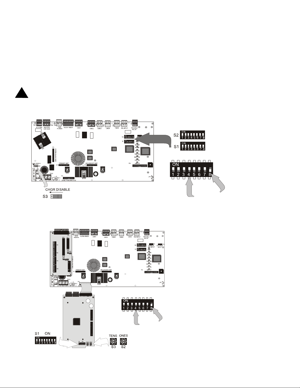
CHAPTER 2 Field Pr ogramming
The ACC-25/50DA can be field programmed using option DIP switches S1 and S2 located in the upper right side of
the mother board. It is recommended that tone selection and background music options be reviewed and approved by
the local AHJ. Programming DIP switches are also located on the ACC-ZPM Zone Page Module. DIP switches are
also located on the optional Message Generator Module (FC-MGM). Refer to the following illustrations for details
on DIP switch placement in the ON and OFF positions.
CAUTION: In order to minimize risk of damage to any circuits, do not use conductive tools when configuring DIP
!
switches.
FIGURE 2-1:Field Programming DIP Switches
S3 shown in Charger
Enabled position
FIGURE 2-2:Field Programming DIP Switch for ACC-ZPM
Distributed Audio Panel Mother Board
Switches 1 through 7
shown in OFF position
AC25DAZSSWTC.CDR
Switch 8 shown
in ON position
AC25DASWTC.CDR
22
ACC-ZPM
Switches 1 through 7
shown in OFF position
EIA-485 Addressing Switches
ACC-25/50DA 52265:B 1/30/08
Switch 8 shown in
ON position
Page 23

S1 DIP Switch Settings on Distributed Audio Motherboard
2.1 S1 DIP Switch Settings on Distributed Audio Motherboard
The following tables list the ACC-25/50DA Series programmable features and the DIP switch settings required to
select a particular feature. A detailed description of each feature is presented in the following pages.
TABLE 2-1: S1 DIP Switch Settings on Distributed Audio Panel Motherboard
S1 DIP Switch ON OFF
1
Enable Temporal Pattern Tone
(switches 2 & 3 must be OFF)
2 This switch works in conjunction with switch 3 to determine tone to be generated over speakers
Tone transmitted before and after message transmission and as backup tone if message fails:
2 OFF, 3 OFF = Steady Tone
3
2 OFF, 3 ON = Slow Whoop Tone (factory default)
2 ON, 3 OFF = Hi-Lo Tone
2 ON, 3 ON = Chime
4 not used
5 not used
6 not used
1
7
1
8
This switch works in conjunction with switch 8 for message control selection and message length.
This switch works in conjunction with switch 7 for message control selection and message length.
Refer to Table 2-2 for valid settings of switches 7 & 8.
1. Only with FC-MGM option module installed.
Disable T emporal Pattern Tone (factory default)
(tone generated as selected by switches 2 & 3)
The selection of the source of the audio which will be transmitted by the amplifier in a 25 watt system (both amplifiers in a 50 watt system) is determined by three factors:
DIP switch settings as detailed in Section 2.2 "S2 DIP Switch Settings on Dist rib uted Audio Mother-
board" on page 24
activation of CMD Command Inputs (A CC-25/50DA, or via the Serial Control link from the ACC-25/
50ZS main panel)
installation of the optional FC-MGM Message Generator Module
The following table details which audio sources will be transmitted depending on the conditions stated above and the
number of messages that can be recorded along with the duration of each message.
TABLE 2-2: DIP Switch S1, Switches 7 & 8
S1 DIP Switch Settings
for Switches:
78
00
0 0 60 sec.
1 0 30 sec.
0 1 20 sec.
1 1 15 sec.
1. This table is only valid for ACC-25/50DA configurations. The CMD1 through 5 inputs are ignored by the
ACC-25/50DAZS, which is controlled, instead, via the Zone System serial link from the ACC-25/50ZS. CMD3,
CMD4 and CMD5 still require End-of-Line resistors.
2. The ACC-25/50DAZS supports local message generation for backup purposes only. All voice messages are input
from the ACC-25/50ZS panel.
3. CMD1 has the highest priority, CMD5 has the lowest priority.
4. CMD1 does not open for trouble co nditions when configured as an ACC-25/50DAZS
5. Tone Only is the factory default setting. If the FC-MGM module is not installed, this configuration provides tone
only.
Message
Length
FC-MGM
Tone Only
(no message)
5
3 4
CMD1
Riser to
AAM1& 2
Riser to
AAM1 & 2
Riser to
AAM1 & 2
Riser to
AAM1 & 2
Riser to
AAM1 & 2
Audio Signal Control
1 2
CMD2 CMD3 CMD4 CMD5
Tone to
AAM1 & 2
message1 to
AAM1 & 2
message1 to
AAM1 & 2
message1 to
AAM1 & 2
message1 to
AAM1 & 2
message2 to
AAM1 & 2
message2 to
AAM1 & 2
message2 to
AAM1 & 2
message3 to
AAM1 & 2
message3 to
AAM1 & 2
message4 to
AAM1 & 2
ACC-25/50DA 52265:B 1/30/08 23
Page 24

S2 DIP Switch Settings on Distributed Audio Motherboard
2.2 S2 DIP Switch Settings on Distributed Audio Motherboard
TABLE 2-3: S2 DIP S witch Settings on Distributed Audio Panel Motherboard
S2 DIP Switch ON OFF
1 not used
2
3
4 not used
5
6
7 not used
8
1. NFPA 72 requires that speakers used as alarm notification appliances on fire alarm systems not be used for nonemergency
purposes. Consult with the Local AHJ for authorization to use background music. Only 20 watts of power can be supplied
per amplifier if background music is enabled.
2. Background music is disabled during AC loss conditions to preserve battery power.
3. For ACC-25/50DAZS, Background Music is prohibited.
4. When CMD1 and CMD2 are configured for reverse polarity, the NAC cannot be Coded.
5. If the FC-MGM is installed, set the Message Repeat setting to Infinite (FC-MGM SW1: 6, 7 & 8 = ON) for proper operation.
6. For proper backup operation during riser loss conditions, the message repeat setting in the ACC-25/50ZS panel must be set to
infinite (refer to manual P/N: 51889 for additional information).
Only AC Loss Relay will transfer upon an AC
loss condition.
Enable Background Music 1 2
Command Input 1
Activation on Contact Closure
Command Input 2
Activation on Contact Closure
Local Generation of Evacuation Tone (or
voice message if FC-MGM is installed) if
audio riser fails
5 6
3
The CMD1 & Form-C Trouble Relays will track the AC
Loss Relay and transfer upon an AC loss condition.
Disable Background Music (factory default)
Command Input 1
Activation on NAC polarity reversal (factory default)
Command Input 2
Activation on NAC polarity reversal (factory default)
Disable Local Generation of Evacuation Tone if audio
riser fails (factory default)
4
4
2.3 S3 - Battery Charger Switch on Distributed Audio Motherboard
This switch controls whether the ACC-25/50DA Distributed Audio Panel will charge the system batteries or if an
external battery charger will be used.
Right Position = Distributed Audio Panel charges batteries
S3
Note: The Distributed Audio Panel still indicates battery fault conditions even when internal battery charger is not
used.
Left Position (as illustrated) = external charger is being used to charge batteries.
24
ACC-25/50DA 52265:B 1/30/08
Page 25

ACC-ZPM Zone Page Module
2.4 ACC-ZPM Zone Page Module
The ACC-ZPM Zone Page Module has two rotary address switches S2 and S3 which are used to set the EIA-485
address of the module for communication with the ACC-25/50ZS over the Zone System serial link.
2.4.1 S1 DIP Switch Settings on ACC-ZPM
S1 DIP switch is not used. All switches are factory set to the OFF position and must remain OFF.
2.4.2 S2 and S3 Addressing Rotary Switches
T wo addressing switches are located at the bottom right of the ACC-ZPM Zone Page Module. The switches are used
to set the EIA-485 address of the ACC-ZPM to allow communication between it and the ACC-25/50ZS. This communication link allows the ACC-25/50ZS to control the speaker circuits.
T o set the address, use a small nonconductive flat-blade screw driver to turn the switch dial so the arrow points to the
correct address number. The factory default setting is S3 = 0 and S2 = 1. The following illustration shows the
switches set for address 01 with S3 (Tens) set to 0 and S2 (Ones) set to 1.
FIGURE 2-3:ACC-ZPM Addressing Switches
2.4.2.1 ACC-ZPM Addressing for Style Y (Class B) Audio Circuits
The ACC-ZPMK, which is located in the main ACC-25/50ZS Audio Panel, is set to address 01 (as illustrated in
Figure 2-3) for communication with the FACP via the ACS link and will control Style Y (Class B) Audio Zones
1-8. The ACC-ZPM modules located in the ACC-25/50DAZS Distributed Audio Panels connected to the ACC25/50ZS Audio Panel, must be set to consecutive addresses, starting with address 01, and will control Style Y
(Class B) Audio Zones 9-16 and 17-24 as detailed in the following table.
Module Address (S2 & S3) Style Y (Class B) Audio Zone
ACC-ZPMK 01 1 - 8
ACC-ZPM (1st) 01 9 - 16
ACC-ZPM (2nd) 02 17 - 24
Note: Switch SW2 on the ACC-ZSM module is set to Class B on all ACC-ZSM(s). See 'ACC-ZSM Zone Splitter
Module' on page 26.
2.4.2.2 ACC-ZPM Addressing for Style Z (Class A) Audio Circuits
The ACC-ZPMK, which is located in the main ACC-25/50ZS Audio Panel, is set to address 01 (as illustrated in
Figure 2-3) for communication with the FACP via the ACS link and will control Style Z (Class A) Audio Zones
1 - 4. The ACC-ZPM modules located in the ACC-25/50DAZS Distributed Audio Panels connected to the ACC25/50ZS Audio Panel, must be set to consecutive addresses, starting with address 01, and will control Style Z
(Class A) Audio Zones 5-8, 9-12, 13-16, 17-20 and 21-24 as detailed in the following table.
Module Address (S2 & S3) Style Z (Class A) Audio Zone
ACC-ZPMK 01 1 - 4
ACC-ZPM (1st) 01 5 - 8
ACC-ZPM (2nd) 02 9 - 12
ACC-ZPM (3rd) 03 13 - 16
ACC-ZPM (4th) 04 17 - 20
ACC-ZPM (5th) 05 21 - 24
Note: Switch SW2 on the ACC-ZSM module is set to Class A on all ACC-ZSM(s). See 'ACC-ZSM Zone Splitter
Module' on page 26.
ACC-25/50DA 52265:B 1/30/08 25
Page 26

ACC-ZSM Zone Splitter Module
2.5 ACC-ZSM Zone Splitter Module
Two switches on the ACC-ZSM Zone Splitter Module are used to configure the speaker circuits connected to it.
• SW1 - used to configure the circuits for split amplifier application. Setting the switch to the AAM 1 & 2 position directs the audio from Amplifier 1 to the first two Class A circuits or first four Class B circuits, and the
audio from Amplifier 2 to the next two Class A circuits or next four Class B circuits. Setting the switch to the
AAM1 position sends the audio from Amplifier 1 to all circuits. IMPORTANT! Set SW1 to AAM1 when
Amplifier 2 is configured to backup Amplifier 1.
• SW2 - used to configure all circuits for Class A (Style Z) or Class B (Style Y) operation.
SW1, which is shown in the AAM 1 & AAM 2
SW2, which is shown in the Class B position, configures all circuits for Class B (Style Y) wiring.
This is the factory default setting.
position is set for split amplifier operation.
Note that the factory default setting is AAM1
only for single amplifier operation.
2.6 Switch SW1 on ACC-AAM25 Audio Amplifier Module
When the amplifier is mounted in the secondary location (connector P2) on the main circuit board, switch S1 on the
ACC-AAM25 is used to configure the amplifier for backup applications. Positioning switch S1 to the Up (Backup
On) position sets the amplifier to act as a backup to the primary amplifier installed in the system. Positioning switch
S1 to the Down position configures the amplifier to act as an additional system amplifier. See Section 3.8.1 "Audio
Amplifier Module [ACC-AAM25]" on page 39, for the location of the switch on the ACC-AAM25 board and Section
5.4 "One Speaker Circuit With Backup" on page 52, for details on wiring the amplifiers for backup applications.
2.7 Switch SW1 Settings on Optional FC-MGM Module
SW1 - DIP Switch Settings
FIGURE 2-4:Field Programming Switches on FC-MGM Module
Switch 1 set to ON
Switches 2 to 8 set to OFF
6 2
220
35v
JP1
MESSAGE
TROUBLE
P2
SPKR
PC MIC/LINE OUT
SW1
ON
1 2 3 4 5 6 7 8
PLAYBACK
6 2
220
35v
SW4
J2
RCA
J1
MIC INPUT
P1
RECORD
SW2
RECORD
BYPASS
SW3
FC-MGM.cdr
VXMGMdip.cdr
26
ACC-25/50DA 52265:B 1/30/08
Page 27

Switch SW1 Settings on Optional FC-MGM Module
Custom messages can be recorded from four different audio sources:
PC microphone
PC line out
Microphone (P/N:FC-MICROPHONE)
RCA jack connected to an audio source
Note: Only one
of the four audio sources can be connected at a time.
FC-MGM SW1 DIP switch settings are as follows:
• Switch 1 - used to select an input for digital voice message recording:
ON = select alternate sources for message recording
OFF = select RCA Jack for message recording (factory default)
• Switch 2 - used to configure the mini Audio Jack for digital voice message recording from either a PC micro-
phone or a PC audio output card:
ON = select PC line out for message recording
OFF = select PC microphone for message recording (factory default)
• Switch 3 - used to enable recording of digital voice message:
OFF = disable recording of message (factory default)
ON = enable recording of message
• Switch 4 - used to determine if a tone will be generated before the message is transmitted:
OFF = No tone before message
ON = Tone before message (factory default setting)
• Switch 5 - used to determine if a tone will be generated after the message is generated:
OFF = No tone after message
ON = Tone after message (factory default setting)
• Switch 6, 7 and 8 - used to determine the number of times the voice message will repeat.
TABLE 2-5: Switch Settings for Message Repeat
SWITCH
6
ON OFF OFF 3
OFF ON OFF 4
ON ON OFF 6 (factory default)
OFF OFF ON 8
ON ON ON INFINITE (until FACP trigger is reset)
SWITCH
7
SWITCH
8
NUMBER OF TIMES TO REPEAT DIGITAL
VOICE MESSAGE
SW2 - Record Bypass Switch (on optional FC-MGM Module)
This switch, when placed in the down position, prevents accidental erasure of stored voice messages. See 'Operating
Instructions' on page 43 for additional information.
•UP Position = The stored digital voice message may be overwritten with a new one.
•Down Position = The stored digital voice message can not be overwritten (factory
default setting).
ACC-25/50DA 52265:B 1/30/08 27
Page 28

Installation
CHAPTER 3 Installation
3.1 Mounting
FIGURE 3-1:ACC-25/50DA Cabinet
The cabinet may be surface mounted. The door is removable during
the installation period by opening and lifting it off the hinges. The
cabinet mounts using two key slots at the top of the backbox and two
additional 0.250" diameter holes located at the bottom.
Carefully unpack the system and check for shipping damage. Mount
the cabinet in a clean, dry , vibrat ion-free area where extreme temperatures are not encountered. The area should be readily accessible with
sufficient room to easily install and maintain the panel. Locate the
top of the cabinet approximately five feet above the floor with the
hinge mounting on the right. Determine the number of conductors
required for the devices to be installed. Sufficient knockouts are pro-
ACC2550DA.CDR
vided for wiring convenience. Select the appropriate knockout(s) and
pull the required conductors into the box. Note that knockouts are
also located on the back of the cabinet. All wiring should be in accordance with the National and/or Local codes for fire alarm systems.
3.2 Backbox Installation
Surface Mounting
The circuit board contains static-sensitive components. Always ground yourself with a proper wrist strap before
handling any boards so that static charges are removed from the body. Use static suppressive packaging to protect
!
electronic assemblies.
Open the door and lift the door off the pin hinges.
Remove the main circuit board and transformer from the backbox before installation. Set the board and
transformers aside in a safe, clean place. Avoid static discharge which may damage static sensitive
components on the board
Mark and predrill holes for the top two backbox keyhole mounting bolts usin g the dim e nsions shown.
Install two upper fasteners in the wall with the screw heads protruding.
Using the upper 'keyholes', mount the backbox over the two screws.
Mark and drill the lower two holes.
Install the remaining fasteners and tighten all fasteners to complete backb ox mounting.
Carefully reinstall the main circuit board and transformer, using appropriate precautions to prevent
damage to components due to static discharge.
28
ACC-25/50DA 52265:B 1/30/08
Page 29

Backbox Installation
Draw wires through the respective knockout locations.
FIGURE 3-2:Cabinet Dimensions & Knockout Locations
Top
Back
of
Box
Left Side
Back
of
Box
Right Side
Back
of
Box
Hinge
ACC25ENC.CDR
Hinge
Bottom
ACC-25/50DA 52265:B 1/30/08 29
Page 30

Backbox Installation
FIGURE 3-3:Distributed Audio Panel Backbox
30
ACC25DACAB.CDR
ACC-25/50DA 52265:B 1/30/08
Page 31

Backbox Installation
3.2.1 Transformer Installation
!
Caution: Before installing any modules or cables, make certain all power (AC and DC) has been removed.
1. Locate four threaded mounting studs in the bottom left corner of the backbox (refer to backbox il lustration
below).
2. Position the Transformer Assembly with the top and bottom mounting brackets on the mounting studs, with
cable assembly oriented to the top as illustrated below.
3. Secure the Transformer to the studs with the four supplied nuts. Do not tighten one of the nuts until the next
step.
4. Connect a wire from a solid earth ground to one of the Transformer mounting studs and tighten the nut. This
connection is necessary in order to provide proper lightning and transient protection for th e panel.
5. Plug Transformer cable assembly into connector P10 which is located in the lower left side of the main circuit
board. Note that the Transformer cable connector is keyed to prevent incorrect connection.
6. Complete the installation by connecting the AC power wires to Hot, Neutral and Earth terminals of TB10 on
the main circuit board.
7. If batteries are being used, connect the batteries (18 AH maximum) to connector P11 located to the bottom left
of the main circuit board.
8. Apply power to the panel.
FIGURE 3-4:Installation of Power Supply Transformer
P10 Connector Transformer
Transformer Mounting Studs
P11 Connector - Battery
AC Terminal TB10
Transformer Assembly
Backbox
Main Circuit Board
Mounting Studs
AC25DAXMNT.CDR
Transformer Mounting Studs
ACC-25/50DA 52265:B 1/30/08 31
ACC25bkb.CDR
Page 32

Operating Power
3.3 Operating Power
CAUTION: Several different sources of power can be connected to this panel. Disconnect all sources of power
!
before servicing. The panel and associated equipment may be damaged by removing and/or inserting cards, modules
or interconnecting cables while this unit is energized. Also, many components are static sensitive which require the
use of proper grounding techniques.
AC Power and Earth Ground Connection
Primary power source is 120 VAC, 50/60 Hz, 1.0 amp for the ACC-25/50DA. Overcurrent protection for this circuit must comply with Article 760 of the National Electrical Code (NEC) and/or local codes. Make certain that
the AC mains circuit breaker is off
a pair of wires (with ground conductor) from the protected premises main breaker box to TB10 of the main circuit
board. Use 14 AWG (1.6 mm O.D.) or heavier gauge wire with 600V insulation. No other equipment may be
connected to this circuit and it may not contain any power disconnect devices. A separate Earth Ground connection must be made to ensure proper panel operation and lightning and transient protection. Connect the Earth
Ground wire (minimum 14 AWG) to one of the transformer mounting studs. Do not use conduit for the Earth
Ground connection since this does not provide reliable protection.
Secondary Power Source (Batteries)
Observe polarity when connecting the batteries. Connect the battery cable to P11 on the main circuit board, using
the plug-in connector and cable provided. The battery charger is current-limited and capable of recharging sealed
lead acid type batteries (See Figure 3-5 for battery orientation). The charger shuts off when the system is in
alarm. Refer to page 61 for calculation of the correct battery rating.
!
CAUTION: Battery contains sulfuric acid which can cause severe burns to the skin and eyes, and can destroy
fabrics. If contact is made with sulfuric acid, immediately flush the skin or eyes with water for 15 minutes and
seek immediate medical attention.
before making any wiring connections between the mains and the panel. Run
FIGURE 3-5:Operating Power Connections
ACC-ZSM Mounting Bracket
32
AC25POWR.CDR
ACC-25/50DA 52265:B 1/30/08
Page 33

Auxiliary DC Power Output Connections
3.4 Auxiliary DC Power Output Connections
The Special Application Auxiliary DC power output is power-limited.
FIGURE 3-6:Auxiliary Power Connection
Special Application Power (35 mA @ 24 VDC) is nonresettable power
suitable for powering control modules and End-of Line Power supervision
relays. See Device Compatibility Document for compatible devices.
2550DATB9.CDR
3.5 Input Circuits
3.5.1 Master Command Bus
The Master Command Bus Input circuit, when used with the ACC-25/50 Series, can be used to add paging flexibility.
All field wiring for each circuit is power-limited and supervised for opens and ground faults. Note that zero impedance to ground will be indicated as a ground fault.
The Master Command Bus Input circuit is triggered by a reverse polarity signal such as the one from the Master
Command Output Bus on the ACC-25/50 Series. Master Command input and output terminals are provided to allow
connection to additional audio distribution panels.
When connecting the Master Command Output of ACC-25/50 Series to the Master Command Bus Input of distributed audio panels, the wiring must be supervised by a 4.7K EOL resistor connected across the out terminals of Master
Command Bus Output on the last panel.
In Example 1 illustrated below, the Master Command bus is activated during paging, which routes paging audio from
the riser to the Distributed Audio Panel speakers.
FIGURE 3-7:Example 1 - Activating Multiple Distributed Audio Panels with Master CMD Output Bus
(Paging active polarities shown )
General or
VECP ELR
Master Command
Bus
Distributed Audio Panel
ACC-AAM25
ELR
Master Command
Bus
Distributed Audio Panel
audio riser
audio
riser
Voice Evacuation
Control Panel
Emergency All-Call
Master CMD
ACC-AAM25
(VECP)
Paging
Output Bus
ACC2550Dout.cdr
The maximum line resistance from the main ACC-25/50 Series to the last Distributed Audio Panel is 130 ohms (65
ohms per conductor).
Note: The ACC-25/50DAZS uses the Zone System serial link for paging operations, therefore Master Command Bus
connections are only used with ACC-25/50DA panels.
ACC-25/50DA 52265:B 1/30/08 33
Page 34

Input Circuits
3.5.2 CMD Input Circuits
The Distributed Audio Panel has five Command Input circuits, which are used to activate the panel amplifiers which,
in turn, transmit an audio signal over the system speakers. All field wiring for the circuits is power-limited and supervised for opens and ground faults. Note that a ground fault is indicated when there is zero impedance to ground.
CMD1 and CMD2 Command Input circuits can be independently field programmed to be triggered by a contact
closure or by the reverse polarity of a Notification Appliance Circuit. (IMPORTANT! When CMD1 and CMD2 are
configured for reverse polarity, the NAC cannot be Coded). Input and output terminals are provided for CMD1 and
CMD2 to allow placement of the Distributed Audio Panel anywhere along a Notification Appliance Circuit allowing
nondedicated use of host FACP NAC for triggering. CMD1 has relay contacts (maximum current 2.0 amps) before
the out terminals which will open the outgoing NAC circuit during a Distributed Audio Panel trouble condition. This
causes an NAC trouble at the host FACP. Note that CMD1 and CMD2 configurations can be independently set so
that both circuits are triggered by the same type of input or by different types of inputs (see Figure 3-8 on page 34).
FIGURE 3-8:Command Input Circuits
alarm polarity shown
Style Z (Class A)
FACP EOL Resistor
(for Style Y - Class B only)
Contact Closure trigger such as alarm contact (4.7K, 1/4 watt
EOL Resistors P/N: 27072)
Polarized Strobe
Polarized Strobe
Polarized Strobe
NAC reverse polarity trigger
(alarm polarity shown)
Polarized Strobe
Polarized Strobe
Polarized Strobe
Audio Distribution Panel
1 2
1 2
AC25DATB5.CDR
1 2
CMD1 is programmed for reverse polarity and CMD2 is programmed for contact closure. CMD3, CMD4 and CMD5
Command Input circuits are triggered by a contact closure only.
3.5.3 Trouble Contact Input
The Trouble Contact Input is a nonsupervised, non-isolated input which can be used to monitor the trouble contacts
of remote battery chargers, power supplies, etc. The maximum contact closure operation @ 30VDC current is 1.2
mA. Note: Trouble Input is not suitable for AC Failure Report.
Remote Power Supply or
Battery Charger
Normally Open
Contacts
34
1 2
AC25DATB12.CDR
ACC-25/50DA 52265:B 1/30/08
Page 35

Output Circuits
3.6 Output Circuits
3.6.1 Trouble Relay - TB1
The main circuit board provides a Form-C Trouble relay, for independent monitoring, rated for 2.0 amps @ 30
VDC (resistive) and 0.6 amp @ 30 VAC (resistive). This relay is ‘fail safe’, meaning that it is normally energized.
Should system power shut off, this relay will deenergize, transferring its contacts.
FIGURE 3-9:Trouble Relay
TB1
3.6.2 AC Power Loss Relay - TB11
The main circuit board provides a Form-C AC Power Loss relay rated for 2.0 amps @ 30 VDC (resistive) and 0.6
amps @ 30 VAC (resistive).
FIGURE 3-10:AC Power Loss Relay
2550ACRL.CDR
Shown in energized,
nontrouble condition
2550DAACRL.CDR
TB11
3.6.3 Notification Appliance Circuit (Speakers)
Each Amplifier Module provides one Notification Appliance Circuit for speakers. The circuit can be wired
Style Y (Class B) or Style Z (Class A). Each supervised and power-limited circuit is capable of 25 watts of
power. The maximum total capacitance for each speaker circuit cannot exceed 250 uF. Refer to the Device
Compatibility Document for a listing of compatible speakers.
!
CAUTION: Match proper polarity connections to field wiring and speakers. Polarity shown is in the standby and
alarm conditions.
FIGURE 3-11:Speaker Circuit Connections
ELR Resistor required for Style Y Class B only
4.75K, 1 watt, P/N:75470
Shown in energized,
normal AC Power condition
Style Z (Class A) Circuit
Shield
2550CKT1.CDR
Shielded cable is not required, however, shielded cable will reduce RFI/EMI emissions and susceptibility . For
additional information, refer to Appendix C "Wiring Requirements" on page 66.
ACC-25/50DA 52265:B 1/30/08 35
Page 36

Output Circuits
3.6.4 ACC-ZPM Zone Page Module - Zone System Serial Link
The ACC-ZPM Zone Page Module provides control of the speaker circuits connected to the ACC-ZSM Zone
Splitter Module. In order to provide program control, an EIA-485 link must be established between the ACCZPM and the ACC-ZPMK located in the ACC-25/50ZS Panel. This is accomplished by wiring TB1 on the Zone
Page Module to TB2 on the ACC-ZPMK. Riser conductors must be installed in accordance with the survivability
from attack by fire requirements in National Fire Alarm Code, NFPA 72. Circuit wiring requires a ferrite bead as
illustrated in Figure 3-12.
Note that the ACC-ZPM must be set to an address between 01 and 05.
FIGURE 3-12:Zone Page Module
Ferrite Bead
+ -
Style Z (Class A) return
from ACC-25/50DAZS
S1 DIP switches - Refer to
Programming Section
To Other
ACC-25/50DAZS
Panels Located
Down Stream
36
ACC-ZPMK
ACC-25/50ZS
Large gauge wire should be
looped through bead at least once
as illustrated. Smaller gauge wire
can be looped more often
ACC-25/50DA 52265:B 1/30/08
DIP Switch Setting - set for number
of ACC-ZPMs connected (1 - 8)
Refer to Programming Section of
ACC-25/50ZS Manual (51889)
Ferrite Bead in open position
ACC-ZPM
Ferrite Bead in closed position
Set S2 & S3 to
Address 01-05
refer to Programming
Section
Page 37

Output Circuits
3.6.5 ACC-ZSM Zone Splitter Module
The ACC-ZSM Zone Splitter Module provides connections for four Style Z (Class A) or eight Style Y (Class B)
speaker circuits. Circuits are configured by setting switch SW2 on the ACC-ZSM to the Class A or Class B
position (refer to Section 2.5 "ACC-ZSM Zone Splitter Module" on page 26).
FIGURE 3-13:Zone Splitter Module
CAUTION! For correct supervision in the split amplifier configuration, ACC-ZSM TB2 pins 1 & 2
must connect to ACC-AAM25 #1 and ACC-ZSM TB9 pins 1 & 2 must connect to ACC-AAM25 #2
ELR Resistor required for
Style Y (Class B) only
4.75K, 1 watt, P/N:75470
Class B (Style Y) Wiring
Dummy load all unused
circuits with 4.75K, 1 watt
resistor, P/N: 27589 when
configured for Class B
wiring.
To TB1 pins 3 & 4
on ACC-AAM25 #1
To TB1 pins 3 & 4
on ACC-AAM25 #2
4.75K, 1 watt resistor,
P/N: 27589 required
when ACC-AAM25 is
connected to terminals.
SW1 shown set
for Split Amplifier
operation, where
TB1 & TB4 are
driven by ACCAAM25 #1 and
TB5 & TB6 are
driven by ACCAAM25 #2.
Class A (Style Z) Wiring
Jumper all unused circuits (+ to +
and - to -) when configured for
Class A wiring.
ACC-25/50DA 52265:B 1/30/08 37
SW2 shown set
for Class B wiring
acczsmwire.CDR
Page 38

UL Power-limited Wiring Requirements
3.7 UL Power-limited Wiring Requirements
Power-limited and nonpower-limited circuit wiring must remain separated in the cabinet. All power-limited circuit
wiring must remain at least 0.25" away from any nonpower-limited circuit wiring. Furthermore, all power-limited
and nonpower-limited circuit wiring must enter and exit the cabinet through different knockouts and/or conduits. A
typical wiring diagram for the Distributed Audio Panel with two speaker circuits is shown below.
FIGURE 3-14:Typical Wiring Diagram for UL Power-limited Requirements
Nonpower-limited Circuit
Power-limited Circuit
Nonpower-limited Circuit
AC Power
Nonpower-limited
38
AC25DAULPW.CDR
ACC-25/50DA 52265:B 1/30/08
Page 39

Installation of Option Modules
3.8 Installation of Option Modules
3.8.1 Audio Amplifier Module [ACC-AAM25]
The optional audio amplifier module is identical to the module provided with the factory standard panel configuration. It can be used to provide a second 25 watt speaker circuit, increasing the total Distributed Audio Panel power to
50 watts, or it can be used as a backup amplifier. LEDs on the amplifier module are for Amp Supervision (green indicates amp functional) and Circuit Trouble (yellow - indicates wiring fault or amplifier fail). Connector J1 of the
audio amplifier module plugs into connector P2 located at the bottom center of the main circu it board.
!
Caution: Before installing any modules, make certain all power (AC and DC) has been removed. In addition, circuit
boards contain static-sensitive components, therefore make certain proper grounding procedures are followed.
1. For ease of access, all wiring should be connected to the terminals on the main circuit board terminal blocks
prior to installing the secondary Audio Amplifier Module.
2. Remove mounting screw shown, from the main circuit board, and save (refer to illustration below).
3. Install one supplied metal standoff in location from which mounting screw was removed in Step 2.
4. Install the Audio Amplifier Module by carefully aligning the amplifier's J1 connector with the P2 connect or
on the main circuit board. Press the Module securely into place making certain not to bend or break any connector pins.
5. Secure the Audio Amplifier Module with the supplied screws plus the screw removed in Step 2. It is impor-
tant to secure the module with the metal screws in order to help protect against electrical transients.
6. Configure the Audio Amplifier for primary or backup amplifier operation by setting switch S1 on the
amplifier:
(1) Position switch S1 in the DOWN position for primary operation which adds the new amplifier's 25
watts to total system power (50 watts total).
(2) Position switch S1 in the UP 'Backup On' position to configure the amplifier as a backup in the
event the primary amplifier fails. IMPORTANT! ACC-25/50DAZS ONLY
ZSM to AAM1 for backup configuration.
7. Check to make certain the factory installed jumpers are in place on P1 of the Audio Amplifier Module(s). Do
not remove unless installing the FC-XRM70 Transformer Module. Refer to Figure 3-16 on page 40.
8. Connect field wiring to newly installed amplifier. Refer to Figure 3-11 on page 35 for illustration of speaker
connections if amplifier is being used to expand system power to 50 watts (i.e. providing dual 25 watt speaker
circuits). Refer to Figure 5-3 on page 52 for illustration of connections if amplifier is being used as a backup.
- Set SW1 on the ACC-
FIGURE 3-15:Installation of Optional Audio Amplifier
Switch S1 Backup select
(Step 6)
Factory installed
metal standoff
ACC-AAM25 Audio
Amplifier Module factory supplied on
connector P1 of the
main circuit board
Amp
Supervision
Circuit
Trouble
(Steps 2 & 5)
Amplifier J1 to main circuit board P2 (Step 4)
ACC-AAM25 Audio Amplifier
Module - to connector P2 of the
main circuit board (Steps 4 & 5)
Do not remove jumpers
unless installing FC-XRM70
Module (Step 7)
Remove mounting screw and
install supplied Metal Standoff
(Steps 2, 3 & 5)
ACC25DAMT3.CDR
Factory installed metal standoff (Steps 2 & 5)
ACC-25/50DA 52265:B 1/30/08 39
Page 40

Installation of Option Modules
3.8.2 70.7 V
The 70.7 V
Transformer Module (FC-XRM70)
RMS
Transformer Module can be used to convert the 25 V
RMS
amplifiers for installations where 70.7 V
RMS
speakers already exist or are to be installed. Speaker wiring continues to be supervised during standby, alarm and
while background music is playing when transformer is installed. Transformer connector J1 connects to amplifier
connector P1.
!
Caution: Before installing any modules, make certain all power (AC and DC) has been removed.
1. Carefully remove the ACC-AAM25 Audio Amplifier Module(s) from the main circuit board. Refer to Figure
3-15 on page 39 for installation procedures and reverse the steps.
2. Install the three standoffs supplied with the FC-XRM70 Module by inserting each supplied screw into the
three holes on the solder side of the ACC-AAM25 Audio Amplifier Module(s). Secure each standoff in place
with the screws. Refer to Figure 3-16 for the location of the mounting holes.
3. Reinstall the Audio Amplifier Module(s) following the procedure accompanying Figure 3-15.
4. Remove the two factory installed jumpers from connector P1 of the Audio Amplifier Module(s). Refer to the
illustration in Figure 3-16.
5. Carefully align the J1 connector on the FC-XRM70 Transformer Module(s) with the P1 connector on the
Audio Amplifier Module and press securely into place. Make certain the pins are properly aligned to prevent
bending or breaking of pins.
6. Secure the FC-XRM70 Transformer Module(s) to the Audio Amplifier Module(s) with the supplied screws.
RMS
FIGURE 3-16:70.7 V
Two Factory Installed Jumpers on P1 of Each
Amplifier Module Must be Removed to Install the
70.7 V
Transformer (Step 4)
RMS
Transformer Module Installation
RMS
P1
Install Standoff in
Mounting hole
(Step 2)
ACC-AAM25 Audio
Amplifier Module
TB1 TB2
AMP SUPV
CKT TBL
BACK-UP ON
SW1
J1
P1
T1
Position standoff
(Step 2)
ACC-AAM25 Audio
Amplifier Module
Install Standoffs in
Mounting holes (Step 2)
AC25XFMN.CDR
Install standoff
(Step 2)
Solder side
Secure with
screw (Step 2)
2550STN3.CDR
40
J1
FC-XRM70
Transformer Module
ACC-25/50DA 52265:B 1/30/08
Page 41

Installation of Option Modules
3.8.3 FC-MGM Message Generator Module
The optional FC-MGM Message Generator Module connects to the distributed audio panel by plugging JP1 into
connector P4 which is located in the lower right section of the main circuit board. The FC-MGM provides local
primary or backup message capabilities. The factory programmed voice evacuation message can be changed in the
field by connecting a microphone, a tape player to the RCA Jack or a personal computer audio card output to the mini
Jack resident on the FC-MGM. In addition, built-in tone generators can be programmed to provide a tone before and
after the message or as backup on message failure. DIP switches on the main circuit board and FC-MGM module are
used to program and configure the evacuation message and/or tones. Refer to 2.7 "Switch SW1 Settings on Optional
FC-MGM Module" on page 26, 2.1 "S1 DIP Switch Settings on Distributed Audio Motherboard" on page 23 and 2.2
"S2 DIP Switch Settings on Distributed Audio Motherboard" on page 24.
Caution: Before installing any modules, make certain all power (AC and DC) has been removed.
1. Carefully align connector JP1 on the FC-MGM module with the pins of connector P4 on the main circuit
board
2. Press the FC-MGM module firmly into place on connector P4, being careful not to bend any pins
3. Make certain the module is properly seated on the standoffs
4. Secure the FC-MGM with the supplied screws
FIGURE 3-17:FC-MGM Module Installatio n
FC-MGM Module
ACC-25/50DA 52265:B 1/30/08 41
Install
(Step 2 & 3)
Standoffs
(Step 1)
Standoffs
(Step 1)
Distributed Audio Panel Main Circuit Board
vxptomgm.cdr
Page 42

Installation of Option Modules
3.8.4 FC-LPS Local Playback Speaker Module
The Local Playback Speaker Module can be used to monitor the recorded digital message without transmitting the
message over the system speakers. The speaker module plugs into FC-MGM circuit board. This optional module is
necessary to take advantage of the Playback feature.
The Speaker Module is connected by simply plugging the module connector into P2 of the FC-MGM module. The
Speaker Module may be temporarily installed during the test period.
1. Plug the FC-LPS Local Playback Speaker Module's polarized connector into connector P2 on the FC-MGM
circuit board.
2. Allow the speaker to carefully hang down from the main circuit board being careful not to short any compo-
nents on the board.
3. When testing is completed, remove the speaker connector from P2 on the FC-MGM.
FIGURE 3-18:FC-LPS Installation
Distributed Audio Panel Main Circuit Board
42
Connect to P2
AC25DA-LPS.cdr
FC-MGM Module
FC-LPS Speaker
ACC-25/50DA 52265:B 1/30/08
Page 43

Operating Instructions
CHAPTER 4 Operating Instructions
4.1 Message Recording
4.1.1 Record Push Button (on optional FC-MGM Module)
The switch labeled Record is used for recording a customized message.
FC-MGM
DIP Switch SW1, switches 2 & 3
Record Bypass Switch SW2 in UP position
FC-LPS
for local playback
For Recording, select from one of three sources
Personal Computer
Tape Deck
Microphone
Recording Instructions
Recording a custom message into the distributed audio panel requires that the voice message be input via a microphone (P/N: FC-MICROPHONE) connected to P1 on the FC-MGM, PC microphone, PC audio out connected to
J1 on the FC-MGM or another audio source connected to RCA jack J2. Switch settings in this section are for the
FC-MGM module SW1 DIP switch. After recording a new voice message, wait approximately one minute for
internal supervision to take place before broadcasting the new message over the building speakers.
1. Confirm the Message Control Settings On S1 DIP switches 7 and 8 located on the Distributed Audio Panel
motherboard. These settings will determine the number of messages that can be recorded and the duration of
each. Refer to Table 2-2 on page 23. Note that every time these switch settings are changed, the message(s)
must be rerecorded.
2. Enable recording by setting SW1 switch 3 on the FC-MGM module to the ON position. The Record button is
now ready to be used in record operation.
3. Select the record input source by setting SW1 switch 1 on the FC-MGM module to the OFF position if record-
ing via the RCA jack, or to the ON position if recording via other sources.
4. Configure the mini audio jack, if being used, by setting SW1 switch 2 on the FC-MGM modu le to the ON
position if recording via PC line out or to the OFF position if recording via PC microphone.
5. Slide the Record Bypass switch SW2 on the FC-MGM module to the UP position to enable the message stor-
age device.
ACC-25/50DA 52265:B 1/30/08 43
Page 44

Message Recording
6. Note the following while recording:
• During the message selection process, the Record LED will repeat a flash rate in the following manner:
Initial Record button press to select message #1 - ¼ second flash rate
Press Record button a 2nd time to select message #2 - two ¼ second flashes
Press Record button a 3rd time to select message #3 - three ¼ second flashes
Press Record button a 4th time to select message #4 - four ¼ second flashes
Press Record button a 5th time extinguishes the Record LED and terminates the record process
The total flash interval time is 9 seconds
• To alert the user that there is only two seconds of record time remaining, the LED on the Record button
will change from steady-on to flashing
• The System Trouble LED and Trouble Relay will be on while recording. The system will not respond to
CMD inputs or Zone System serial link controls from the ACC-25/50ZS while recording
• It is not necessary to fill the entire record time. The time limits represent the maximum time allotted
• Factory default messages are replaced with the custom message recordings from the External Audio Input
Jacks or microphone
7. Press the button labeled ‘Record’ the respective number of times to select the appropriate message to record as
described in Step 6. The Record LED will flash as described above. After 9 seconds, the Record LED will
switch to steady on, at which point the recording of the voice message may commence.
8. At the end of recording, the Record button must be pressed again to signal the end of the recorded message.
A void long pauses at the end of the message by promptly pressing the Record button when the voice message
input has stopped. Note that it is not necessary to fill the entire 60 second record time. The time limit repre-
sents the maximum time allotted. If the Record button is not pressed to signal the end of the voice recording,
the unit automatically ends the message at the time out period.
9. Disable recording by setting SW1 switch 3 to the OFF position.
10.Playback the recorded messages for accuracy. This may be done via the ‘Playback’ key or by creating an
alarm or evacuate condition. The Playback feature allows for reviewing the message locally via the FC-LPS
option module without generating the message through the amplifiers.
CAUTION! Be certain to slide the Record Bypass switch SW2 to the Down position when recording is completed.
This will prevent accidental rerecording or deletion of the stored message. It is not possible to record with the SW2
Record Bypass switch in the Down position.
4.1.2 Playback Button
The Playback button can be used to review the stored voice message. By connecting the optional Local Playback
Speaker Module (FC-LPS), the message can be heard without transmitting it over the system speakers.
Message Playback
1. Control the Message Control Settings on S1 DIP switches 7 and 8 located on the Distributed Audio Panel
motherboard. These settings will determine the number of messages that can be played-back. Refer to Table
2-2 on page 23
2. Press the Playback button to automatically start message #1. Press the Playback button a second time to fast-
forward to the 2nd message, a 3rd time for message #3 and a 4th time for message #4
3. During Playback, the following will also occur:
• The green LED on the Playback button will be illuminated
• The message will play until the end or until the Playback button is pressed to advance to the next message or
terminate if it’s the last message
Note that the voice message will playback only once.
44
ACC-25/50DA 52265:B 1/30/08
Page 45

Message Recording
4.1.3 LEDs on Main Circuit Board
Power
A green LED that remains on while DC power to the main circuit board is within correct limits. If this indicator
fails to light under normal conditions, service the system immediately.
AC Power
A green LED that remains on while AC power is within correct limits. If this indicator fails to light under normal
conditions, check for AC power and service the system immediately.
Active
A green LED that turns on when the system is activated into alarm.
System Trouble
A yellow LED that turns on steady to indicate a system trouble.
Tone Trouble
A yellow LED that turns on steady to indicate that the local tone generator is not functioning correctly.
Battery Trouble
A yellow LED that turns on steady when the battery is disconnected or battery voltage drops below acceptable
level.
Charger Trouble
This yellow LED turns on steady when the battery charger voltage falls below an acceptable level.
Ground Fault
This yellow LED turns on steady when a ground fault condition is detected on the system. Zero impedance to
ground will cause a ground fault indication.
Remote Microphone Trouble (Optional FC-MIM Microphone Interface Module)
This yellow LED turns on steady when a remote microphone trouble is detected from the FC-RM or wiring.
4.1.4 LEDs on Optional Message Generator Module (FC-MGM)
Message Generator Trouble (Optional FC-MGM)
This yellow LED turns on steady when the supervised message generator fails or falls below acceptable levels.
Record (Optional FC-MGM)
This green LED is used as a status indicator during the record process.
Playback Active (Optional FC-MGM)
This green LED turns on steady when the message generator is outputting a message.
4.1.5 LEDs on Audio Amplifier Module
Amp Supv - Supervision (Audio Amplifier Module)
This green LED (one on each amplifier), when on steady, indicates that the amplifier is fully functional. The Distributed Audio Panel constantly tests the amplifier to verify proper operation.
Circuit Trouble (Audio Amplifier Module)
This yellow LED (one on each amplifier) turns on steady when a trouble is detected in the amplifier or to indicate
an open or short circuit on the field wiring attached to the amplifier output terminals.
4.1.6 LEDs on ACC-ZPM (ACC-25/50DAZS Only)
ACC COMM
This green LED remains on if communication with the ACC-25/50ZS main panel is active. It extinguishes if
communication is lost.
ACC-25/50DA 52265:B 1/30/08 45
Page 46

Operation
4.2 Operation
The Distributed Audio Panel continuously monitors system status. When no system alarm or local trouble conditions
exist, all LEDs are off except the amplifier supervision LED(s), the Power LED and the AC Power LED located on
the main circuit board and the ACC LED on the ACC-ZPM module installed in an ACC-25/50DAZS. The Notification Appliance Circuits (speakers) are off and all relays are in their normal state. Zone activations and local troubles
are annunciated by the ACC-25/50 Series panel if connected to the Distributed Audio Panel.
4.2.1 Fire Alarm
The Distributed Audio Panel will, upon detection of an alarm condition (CMD1, CMD2 CMD3, CMD4 or CMD5
Inputs active or via the ACS):
Turn on the Active LED steady
Turn on the appropriate Notification Appliance Circuit speakers
Turn on the appropriate Audio Amplifier(s)
Route audio riser or tone/message to appropriate speaker circuit
4.2.2 Fire Alarm Restoral
Turn off the Active LED
Turn off the Notification Appliance Circuits
Turn off the Audio Amplifiers
Turn off the digital voice message or tone at its present point in transmission
4.2.3 General Page Using Optional Remote Microphone (ACC-25/50DA Only)
Pressing the remote microphone push-to-talk switch will direct paging audio to all speaker circuits located at the Distributed Audio Panel.
4.2.4 Emergency Page Using Optional Remote Microphone (ACC-25/50DA Only)
Pressing the remote microphone push-to-talk switch will interrupt the tone/voice message and direct paging audio to
all speaker circuits located at the ACC-25/50DA Panel.
4.2.5 Trouble Condition Response
All trouble conditions are fully supervised in standby and alarm unless otherwise noted and will cause the following
to occur (note that response to AC loss will depend on the setting of S2 switch 2 as shown in Table 2-3 on page 24):
Deenergize the trouble relay causing the contacts to transfer
Turn on the system Trouble LED
Open CMD1 input - ONLY if CMD1 is not
Note: If the audio panel is configured as an ACC-25/50DAZS zone system, CMD1 will not open for
troubles since all troubles are transmitted from the ACC-25/50DAZS to the ACC-25/50ZS via the ACC
control serial link
In addition to the above trouble responses, the following troubles will cause the specific responses noted:
AC Loss
• Turn off the AC Power LED on the main circuit board
• Deenergize AC Loss Relay on the main circuit board
• Deenergize Form-C Trouble and CMD1 contacts if S2 Switch 2 is OFF (refer to Table 2-3 on page 24)
Battery Trouble (low or no battery)
• Turn on the Battery Trouble LED on the main circuit board
Charger Trouble
• Turn on the Charger Trouble LED on the main circuit board
in the alarm state
46
ACC-25/50DA 52265:B 1/30/08
Page 47

Operation
Ground Fault
• Turn on the Ground Fault LED on the main circuit board to indicate zero impedance to ground
Tone Generator Fault
• Turn on the Tone Generator Trouble LED on the main circuit board
Message Generator Trouble (optional FC-MGM)
• Turn on the Message Generator Trouble LED on the FC-MGM
CMD1 or CMD2 (Indicated by the System Trouble LED)
• Both inputs are supervised for open circuit condition when unit is programmed for Normally Open contacts,
otherwise supervision is provided by the host Fire Alarm Control Panel NAC output
CMD3, CMD4 and CMD5 (Indicated by the System Trouble LED)
• All inputs are supervised for open circuit condition
Background Music
• When background music option is enabled via S2 DIP switch 3, the Distributed Audio Panel will constantly
monitor the external audio riser signal. Both amplifiers and speaker wiring continue to be fully supervised
when background music is output from the Distributed Audio Panel. Amplifier faults are reported after 75
seconds. Note that when AC power is lost, the Distributed Audio Panel will shut off background music to
conserve batteries.
*
Note that the Local Authority Having Jurisdiction must approve the use of background music.
*
Background music is not available with the ACC-25/50DAZS.
Amplifier Fault
• Both amplifiers are constantly monitored for proper functionality. Should either amplifier fail, the AMP
SUPV LED will turn off and the Circuit Trouble LED will turn on. When the system is configured for
backup, failure of the primary amplifier will cause the backup amplifier to be switched in.
NAC (Speaker) Output
• The wiring to each amplifier is supervised for opens and shorts at all times in standby and while in alarm or
when background music is enabled
*
. A wiring fault will cause the circuit Trouble LED located on each ampli-
fier module to turn on. It should be noted that the green AMP SUPV LED may remain on for wiring faults.
• The ACC-ZSM wiring to each speaker circuit is supervised for opens and shorts in standby and for shorts
while in alarm. A wiring fault will cause the zone/circuit Trouble LED on the ACC-ZPMK at the main ACC25/50 Series panel corresponding to the affected circuit to turn on.
*Note that the Local Authority Having Jurisdiction must approve the use of background music.
*Background music is not available with the ACC-25/50DAZS.
ACC-ZPM Zone Page Module
• The Zone System serial link wiring between the ACC-ZPM and ACC-25/50ZS is supervised. A loss of com-
munication on the Zone System (EIA-485) serial link will cause a system trouble on the ACC-25/50ZS main
panel and extinguish the ACC COMM LED.
• The ribbon cable between the ACC-ZPM and the motherboard is supervised. A loss of communication will
cause the ACC Comm LED to extinguish on the ACC-ZPM module on the ACC-25/50DAZS and cause a system fault at the ACC-25/50ZS main panel.
Remote Microphone
• The Remote Microphone Module and associated wiring are supervised for faults by the panel
the Trouble LED located on the FC-MIM Microphone Interface Module, which is mounted on the Dis-
tributed Audio Panel panel, will illuminate on a trouble condition
Power ON LED
• A green LED that remains on while power is within correct limits. If this indicator fails to light under normal
conditions, check for AC and battery power and service the system immediately.
*
ACC-25/50DA 52265:B 1/30/08 47
Page 48

Operation
4.2.6 Trouble Condition Restoral
All trouble condition restorals will cause the following to occur:
Reenergize the trouble relay returning contacts to normal position
Turn off the system Trouble LED
Close CMD1 input
In addition to the previous trouble condition restorals, the following specific restorals will occur:
AC restoral
• Turn on the AC PWR LED on the main circuit board
• Reenergize the AC Loss Relay on the main circuit board returning contacts to normal position
Battery restoral
• Turn off the Battery Trouble LED on the main circuit board
Ground Fault cleared
• Turn off the Ground Fault LED on the main circuit board
Tone Generator restoral
• Turn off the Tone Generator Trouble LED on the main circuit board
Message Generator restoral (optional FC-MGM)
• Turn off the Message Generator Trouble LED on the FC-MGM
Amplifier restoral
• The AMP SUPV LED will turn on and the Circuit Trouble LED will turn off. When the system is configured
for backup, restoral of the primary amplifier will cause the backup amplifier to be switched out.
NAC (Speaker) Output restoral
• The wiring to each amplifier is supervised for opens and shorts at all times in standby and while in alarm or
when background music is enabled
each amplifier module to turn off. It should be noted that the green AMP SUPV LED is on.
• The ACC-ZSM wiring to each speaker circuit is supervised for opens and shorts in standby and for shorts
while in alarm. Restoral of a wiring fault will cause the zone/circuit Trouble LED on the ACC-ZPMK in the
ACC-25/50ZS main panel corresponding to the affected circuit to turn off.
*
Note that the Local Authority Having Jurisdiction must approve the use of background music.
*
Background music is not available with the ACC-25/50DAZS.
ACC-ZPM Zone Page Module restoral
• The Zone System serial link wiring between the ACC-ZPM and ACC-25/50ZS is supervised. Restoral of
communication on the Zone System (EIA-485) serial link will cause the system Trouble LED to turn off on
the ACC-25/50ZS main panel.
• The ribbon cable between the ACC-ZPM and audio panel is supervised. Restoral of communication will
cause the ACC Comm LED to turn on at the ACC-ZPM module on the ACC-25/50DAZS and clear the system
fault at the ACC-25/50ZS main panel.
Remote Microphone restoral
• Turn off the Remote Microphone Trouble LED located on the FC-MIM module.
Battery Charger
• Turn off the Battery Charger LED on the main circuit board.
*
. A restoral of a wiring fault will cause the circuit Trouble LED located on
48
ACC-25/50DA 52265:B 1/30/08
Page 49

Application Examples
CHAPTER 5 Application Examples
The ACC-25/50DA is a Distributed Audio Panel which can be used, with a variety of Fire Alarm Control Panels, to
provide emergency audio messages. This chapter contains a few application examples and is not meant to provide a
comprehensive list of all possible Distributed Audio Panel applications. Please refer to the appropriate application
example when following the guidelines below for installation and setup of various audio system configurations.
These guidelines assume that the speaker cabling has already been connected to each ACC-25/50DA(ZS).
5.1 ACC-25/50 & ACC-25/50DA Step-by-Step Install/Setup
1. Connect the output of the ACC-AAM25 located in the ACC-25/50 to the Audio Riser Input of each ACC-25/
50DA to feed the audio to each distributed panel.
2. Connect the Master Command Output of the ACC-25/50 to the Master Command Inputs of each ACC-25/
50DA for All-Call paging control.
3. Connect the CMD Inputs 1-5 of the ACC-25/50 and the CMD Inputs 1-5 of each ACC-25/50DA to the FACP
as required for automatic control.
4. Set S2 DIP switches on the ACC-25/50DA motherboard as required for AC Loss Reporting, Background
music, CMD input trigger type and Local Evacuation Backup.
5. Set S1 DIP switches on the ACC-25/50DA motherboard as required for Tone/Message Control. If the FC-
MGM is installed, configure SW1 DIP switches for Leading/Trailing Tone and Message repeat cycle.
6. Set DIP switches 1, 2 and 3 on S3 of the ACC-25/50 motherboard for Single Zone with activation of 2-5
messages.
7. Record any new messages into the ACC-25/50ZS and the FC-MGM on the ACC-25/50DA if required.
8. Faults are monitored by the FACP via the CMD1 Relay, Trouble Relay and AC Loss Relay.
5.2 ACC-25/50ZS & ACC-25/50DAZS Step-by-Step Install/Setup
1. Connect the output of the ACC-AAM25 located in the ACC-25/50ZS to the Audio Riser Input of each
ACC-25/50DAZS to feed the audio to each distributed panel.
2. Connect the EIA-485 serial communications link wiring from the ACC-25/50ZS to the ACC-25/50DAZS for
manual and automatic control.
3. Set the address wheels on the ACC-ZPM in the ACC-25/50DAZS for address 01-05, where ACC-25/50DAZS
#1=01, ACC-25/50DAZS #2=02 and so on.
4. Set DIP switches 6, 7 & 8 on S1 of the ACC-ZPMK (in the ACC-25/50ZS) for operation with the number of
ACC-25/50DAZS panels (1-5) installed.
5. Set SW1 on the ACC-ZSM of each ACC-25/50DAZS for one or two Audio Amplifier (ACC-AAM25)
configuration.
6. Set SW2 on the ACC-ZSM on each ACC-25/50DAZS for Style Y (Class B) or Style Z (Class A) speaker cir-
cuit wiring.
7. Set S2 DIP switches on the ACC-25/50DAZS motherboard as required for AC Loss Reporting and Local
Evacuation Backup.
8. Set S1 DIP switches on the ACC-25/50DAZS motherboard as required for Tone/Message Control if Local
Evacuation Backup is configured. If the FC-MGM is installed, configure SW1 DIP switch for Leading/Trailing Tone and Message repeat cycle.
9. Set DIP switches 1, 2 & 3 on S3 of the ACC-25/50ZS motherboard for Single Zone with activation of 2-5
messages.
10.Record any new messages into the ACC-25/50ZS and the FC-MGM on the ACC-25/50DAZS if required.
11.Connect the ACC-25/50ZS to the FACP as described in the ACC-25/50ZS manual.
12.Faults on the ACC-25/50DAZS are uploaded to the ACC-25/50ZS via the Zone System Serial Link,
processed, and then uploaded to the FACP via the ACS Link.
ACC-25/50DA 52265:B 1/30/08 49
Page 50

One Speaker Circuit
5.3 One Speaker Circuit
The base configuration of the ACC-25/50DA utilizes a single 25 watt speaker circuit.
5.3.1 Single Channel
In this application, single channel audio from the riser input is routed to the ACC-25/50DA speaker circuit . Th is is
accomplished by using only the CMD1 input for activation.
FIGURE 5-1:One 25 Watt Speaker Circuit - Single Channel
ACC-25/50
Style Z
Style Z
ACC-25/50DA Main Circuit Board
Note: Model R-4.7K, 1 watt
EOL resistor P/N: 75470 (used
for Style Y - Class B only)
alarm polarities shown for all circuits
4.7KΩ ELRs P/N: 27072
ACCDapp51.cdr
50
First ACC-AAM25
ACC-25/50DA 52265:B 1/30/08
Page 51

One Speaker Circuit
5.3.2 Dual Channel
This application provides two channels of input audio that can be directed to the ACC-25/50DA speaker circuit. The
FACP can control the CMD1 and CMD2 inputs on the ACC-25/50DA to route riser audio from the ACC-25/50 or
select the ACC-25/50DA onboard tone generator or optional message generator (FC-MGM) to be routed to the
speaker circuit.
FIGURE 5-2:One 25 Watt Speaker Circuit - Dual Channel
ACC-25/50
Style Z
Style Z
ACC-25/50DA Main Circuit Board
Note: Model R-4.7K, 1 watt
EOL resistor P/N: 75470 (used
for Style Y - Class B only)
Sty le Z
alarm polarities shown for all circuits
4.7KΩ ELRs P/N: 27072
First ACC-AAM25
ACC-25/50DA 52265:B 1/30/08 51
ACCDapp52.cdr
Page 52

One Speaker Circuit With Backup
5.4 One Speaker Circuit With Backup
Another application consists of one distributed audio panel with one amplifier and a single speaker circuit. A second
amplifier can be installed as a backup if desired. This configuratio n i s suitable for small area requiring no more than
25 watts of output power.
Backup Amplifier switch S1 is set to the ‘Backup ON’ position. 18 AWG or larger jumpers connect the Backup
Amplifier TB2 Terminal 3 and Main Amplifier TB2 Terminal 1 as well as Backup Amplifier TB2 Terminal 4 and
Main Amplifier TB2 Terminal 2. Upon failure of the first or main amplifier, the audio from the backup amplifier will
be switched out to the speakers.
Note that in the optional 70.7 VRMS configuration, only the amplifier is backed-up; the FC-XRM70 coupling transformer is not. For this reason, it is not necessary to install an FC-XRM70 transformer module on the backup
amplifier.
5.4.1 Single Channel
In this application, single channel audio from the riser input is routed to the ACC-25/50DA speaker circuit . Th is is
accomplished by using only the CMD1 input for activation.
FIGURE 5-3:One 25 Watt Speaker Circuit With Backup - Single Channel
Note: Model
R-4.7K, 1 watt
EOL resistor
P/N: 75470
(for Style Y Class B only)
Supervisory
Polarity
Shown
ACC-25/50
Style Z
Backup
Audio In
Style Z
alarm polarities shown for circuits
4.7KΩ ELRs P/N: 27072
ACC-25/50DA Main Circuit Board
Backup
Audio In
ACCDapp41.cdr
52
First ACC-AAM25
ACC-25/50DA 52265:B 1/30/08
Backup ACC-AAM25
Page 53

One Speaker Circuit With Backup
5.4.2 Dual Channel
This application provides two channels of input audio that can be directed to the ACC-25/50DA speaker circuit. The
FACP can control the CMD1 and CMD2 inputs on the ACC-25/50DA to route riser audio from the ACC-25/50 or
select the ACC-25/50DA onboard tone generator or optional message generator (FC-MGM) to be routed to the
speaker circuit.
FIGURE 5-4:One 25 Watt Speaker Circuit With Backup - Dual Channel
Note: Model R-4.7K,
EOL resistor
1 watt
P/N: 75470 (used for
Style Y - Class B
only)
Supervisory
Polarity
Shown
ACC-25/50
Sty le Z
Style Z
Backup
Audio In
Style Z
alarm polarities shown for circuits
4.7KΩ ELRs P/N: 27072
ACC-25/50DA Main Circuit Board
Backup
Audio In
ACCDapp42.cdr
First ACC-AAM25
ACC-25/50DA 52265:B 1/30/08 53
Backup ACC-AAM25
Page 54

Two Speaker Circuits
5.5 Two Speaker Circuits
5.5.1 Single Channel
In this application, single channel audio from the riser input is routed to both speaker circuits on the ACC-25/50DA.
This is accomplished by using only the CMD1 input for activation.
FIGURE 5-5:Two Speaker Circuits - Single Channel
Style Z
ACC-25/50
Style Z Style Z
Note: Model R-4.7K,
1 watt EOL
P/N: 75470 (Style Y Class B only)
alarm polarities shown for circuits
ACCDapp71.cdr
ACC-25/50DA Main Circuit Board
54
Supervisory Polarities Shown
First ACC-AAM25
ACC-25/50DA 52265:B 1/30/08
Second ACC-AAM25
Page 55

Two Speaker Circuits
5.5.2 Dual Channel
This application provides two channels of input audio that can be directed to both ACC-25/50DA speaker circuits.
The FACP can control the CMD1 and CMD2 inputs on the ACC-25/50DA to route riser audio from the ACC-25/50
or select the ACC-25/50DA onboard tone generator or optional message generator (FC-MGM) to be routed to the
speaker circuit.
FIGURE 5-6:Two Speaker Circuits - Dual Channel
ACC-25/50
Style Z
Style Z
Note: Model R-4.7K,
EOL resistor
1 watt
P/N: 75470 (used for
Style Y - Class B
only)
Style Z
alarm polarities shown for circuits
4.7KΩ ELRs P/N: 27072
FCDapp72.cdr
ACC-25/50DA Main Circuit Board
Sty le Z
Supervisory Polarity Shown
First ACC-AAM25
ACC-25/50DA 52265:B 1/30/08 55
Second ACC-AAM25
Page 56

ACC-25/50DA High-Power, Multi-floor Application
5.6 ACC-25/50DA High-Power, Multi-floor Application
Input Trigger Output Trigger
CMD1 Audio Riser
from ACC-25/50
CMD2 ACC-25/50DA
message or tone
FIGURE 5-7:Multi-floor
The ACC-25/50DA panel provides distributed message generation:
•Fire floor selects the audio riser from the ACC-25/50
•Adjacent floors select tone/message from the ACC-25/50DA
•Master Command Bus provides All-Call Page trigger
Note: Control Modules in this application can be mounted in the ACC-25/50DA
cabinet using the optional module mounting bracket P/N: ACC-BRKT.
ACC-25/50DA
ADDRESSABLE
FACP
ACC-25/50DA
ACC-25/50DA
ACCDAdis2.cdr
ACC-25/50
56
ACC-25/50DA 52265:B 1/30/08
Page 57

ACC-25/50 Series and ACC-25/50DA Installation
5.7 ACC-25/50 Series and ACC-25/50DA Installation
ACC-25/50 Series Connection to Multiple ACC-25/50DA Distributed Audio Panels (see Table 2-2 on page 23
for Message Control switch settings and ACC 25/50 Manual Doc. 51889).
This application consists of one ACC-25/50 Series and two ACC-25/50DA panels, supplying 150 watts of output
power. The addressable FACP directs one of the five voice messages to both
also manages the routing of audio in the ACC-25/50DA panels via the control modules on the SLC Loop. Audio
from the first amplifier of the ACC-25/50 Series is input to the ACC-25/50DA via the audio riser.
The ACC-25/50 Series is configured for single zone operation when S3 DIP switches 1 and 3 are set to ON and DIP
switch 2 is set to OFF. This causes CMD1 to activate the Fire Message, CMD2 to activate the Fire Alert Message,
CMD3 to activate the T ornado Message, CMD4 to activate the Chemical Spill Message and CMD5 to activate the All
Clear Message. The FACP can route the message generated by the ACC-25/50 Series to the speaker circuits of the
ACC-25/50DA by activating the control module connected to CMD1 of the ACC-25/50DA or it can select the ACC25/50DA local message by activating the control module connected to CMD2.
All Call paging is possible by pressing the All Call button on the keypad of the ACC-25/50 Series. This will activate
the ACC-25/50DA speaker circuits. Keying the microphone will allow announcements to be made on all speaker
circuits.
FIGURE 5-8:ACC-25/50DA Installation
The ACC-25/50 can be used for systems requiring up to 50
watts of audio power.
FACP can be used for automatic control.
Any
The ACC-25/50DA can be added to increase audio power above 50 watts.
ACC-25/50 Series speaker circuits and
Audio Riser
25W Speaker Ckt.
25W Speaker Ckt
Master Command Bus
FACP Control
1. The FACP controls the audio system via the CMD
inputs on the ACC-25/50 and ACC-25/50DA
2. The Audio Riser connects the audio output of the
ACC-25/50 to each of the ACC-25/50DA (s).
3. The Master Command Bus provides an All-Call trig-
ger from the ACC-25/50 to the ACC-25/50DA(s).
Master Command Bus
FACP Control
Audio Riser
T o Additional
Panels
25W Speaker Ckt
25W Speaker Ckt
25W Speaker Ckt
25W Speaker Ckt
ACC-25/50DA
ACC-25/50DA 52265:B 1/30/08 57
Page 58

ACC-25/50 Series and ACC-25/50DA Installation
FIGURE 5-8:ACC-25/50 Series and ACC-25/50DA Installation
Note: Typical illustration of an addressable control panel and addressable control modules. Refer to the
Command Input Specification in Section 1.2, 'Specifications' on page 15, for the voltage range.
Keypad Example
ACC25KY1.cdr
TB6-4 (- Master CMD Bus to 1st ACC-25/50DA)
Optional Class A Return from 2nd ACC-25/50DA
TB6-3 (+ Master CMD Bus to 1st ACC-25/50DA)
Optional Style Z Return from 1st ACC-25/50DA
TB7-5 (- Audio Riser to 1st ACC-25/50DA)
TB7-6 (+ Audio Riser to 1st ACC-25/50DA)
TB6-2
TB6-1
TB7-2
TB7-3
SLC Loop
First Amplifier
Addressable FACP
Addressable Control Modules
or single multimodule
ACC-25/50 Series
Main Circuit Board
Second Amplifier
SLC Loop
4.7KΩ
all ELRs
(P/N: 27072)
TB1-3 (+Terminal of 1st Amplifier to ACC-25/50 )
TB1-4 (-Terminal of 1st Amplifier to ACC-25/50 )
TB7-6 (+ Audio Riser to 2nd ACC-25/50DA )
TB7-5 (- Audio Riser to 2nd ACC-25/50DA )
TB6-4 (- Master CMD Out to ACC-25/50 )
TB6-3 (+ Master CMD Out to ACC-25/50 )
TB6-3 (+ Master CMD Bus to 2nd ACC-25/50DA )
TB6-4 (- Master CMD Bus to 2nd ACC-25/50DA )
TB7-3 (+ Audio Riser to 1st ACC-25/50DA )
TB7-2 (- Audio Riser to 1st ACC-25/50DA )
TB6-2 (- Master CMD Bus to 1st ACC-25/50DA )
TB6-1 (+ Master CMD Bus to 1st ACC-25/50DA )
Optional Style Z Return to
1st amplifier of ACC-25/50
*
or 4.75K , 1 watt End-ofLine resistor (P/N:75470)
only for Class B connection.
Addressable Control Modules
1st ACC•25/50DA
Main Circuit Board
Addressable Control Modules
SLC Loop
4.7KΩ, 1 watt End-of-Line
resistors (P/N:27072)
all resistors
SLC Loop
4.7KΩ, 1 watt Endof-Line resistors
(P/N:27072)
all resistors
AC25app7.cdr
*
2nd ACC•25/50DA
Main Circuit Board
58
ACC-25/50DA 52265:B 1/30/08
Page 59

16 Theater Cineplex Utilizing ACC-25/50ZS
5.8 16 Theater Cineplex Utilizing ACC-25/50ZS
In this application, the Fire Protection System consists of one ACC-25/50ZS with one ACC-25/50DAZS, 16 zones
and an addressable F ACP. Each one of the 16 movie theaters is wired and assigned as a speaker circuit. The FACP is
programmed for Software Zone 33 for Theater 1 through Software Zone 49 for Theater 16. Software Zone 32 is programmed to activate all speaker circuits (All-Call). In addition, the Fire Evacuation Message (Message #1) is entered
into Software Zones 32 - 49.
Automatic control by the FACP is provided through the ACS link to the ACC-25/50ZS. Manual control is possible
via the keypad in the ACC-25/50ZS. Control of Audio Zones 9 - 16 is sent through the ACC Control Serial Link to
the ACC-25/50DAZS. Alarm and Paging audio from the ACC-25/50ZS is delivered to Audio Zones 9 - 16 (ACC-25/
50DAZS) by way of the Audio Riser.
ACC-25/
50DAZS
ACC-25/50ZS
ACC-25/50DA 52265:B 1/30/08 59
Page 60

Audio Command Center 24 Zone System
5.9 Audio Command Center 24 Zone System
In this application, the Fire Protection System consists of one ACC-25/50ZS panel with two ACC-25/50DAZS panels, 24 zones and an addressable FACP. Automatic control by the FACP is provided through the ACS link to the
ACC-25/50ZS. Manual control is possible via the keypad in the ACC-25/50ZS. Control of Audio Zones 9 - 24 is
sent through the ACC Control Serial Link to the ACC-25/50DAZS Distributed Audio Panels. Alarm and Paging
audio from the ACC-25/50ZS is delivered to Audio Zones 9 - 24 (ACC-25/50DAZS panels) by way of the Audio
Riser.
ACC-25/50DAZS
ACC-25/50ZS
ADDRESSABLE FACP
MS-9600 or MS-9200UD
ACC-25/50DAZS
60
ACC-25/50DA 52265:B 1/30/08
Page 61

Power Supply Calculations
CHAPTER 6 Power Supply Calculations
6.1 Overview
This section contains instructions and tables for calculating power supply currents in alarm and standby conditions.
This is a four-step process, consisting of the following:
1. Calculating the total amount of AC branch circuit current required to operate the system
2. Calculating the power supply load current for non-fire and fire alarm conditions and calculating the secondary
(battery) load
3. Calculating the size of batteries required to support the system if an AC power loss occurs
4. Selecting the proper batteries for your system
6.2 Calculating the AC Branch Circuit
The audio distribution panel requires connection to a separate, dedicated AC branch circuit, which must be labeled
FIRE ALARM. This branch circuit must connect to the line side of the main power feed of the protected premises.
No other non-fire alarm equipment may be powered from the fire alarm branch circuit. The branch circuit wire must
run continuously, without any disconnect devices, from the power source to the transponder. Overcurrent protection
for this circuit must comply with Article 760 of the National Electrical Codes as well as local codes. Use 14 AWG
(2.00 mm
2
) wire with 600 volt insulation for this branch circuit.
The ACC-25/50DA requires 1 amp from the AC branch circuit.
6.3 Calculating the System Current Draw
6.3.1 Overview
The secondary power source (batteries) must be able to power the system during a primary power loss. To calculate
the non-fire alarm load on the secondary power source, use Calculation Column 1 in Table 6-2 . The ACC-25/50DA
must support a larger load current during a fire alarm condition and primary power loss. To calculate the fire alarm
load on the secondary power source, use Calculation Column 2 in Table 6-2 .
When calculating current draw and the battery size, note the following:
• ‘Primary’ indicates that the audio panel is being powered by AC
• ‘Secondary’ indicates that the audio panel is being powered by battery backup during AC failure
• All currents are given in amperes (A) and refer to the DC
shows how to convert milliamperes and microamperes to full amperes
TABLE 6-1: Converting to Full Amperes
To convert.... Multiply Example
Milliamperes (mA) to
amperes (A)
Microamperes (µA) to
amperes (A)
mA x 0.001 3 mA x 0.001 = 0.003 A
µA x 0.000001 300 µA x 0.000001 = 0.0003 A
current being supplied by the panel. Table 6-1
ACC-25/50DA 52265:B 1/30/08 61
Page 62

Calculating the System Current Draw
6.3.2 How to use Table 6-2 to calculate system current draws
1. Enter the quantity of devices in both columns
2. Enter the DC current draw where required. Refer to the Device Compatibility Document for compatible
devices and their current draw
3. Calculate the current draws for each in both columns
4. Sum the total current for each column
5. Copy the totals from Column 1 and Column 2 to Refer to Table 6-3 on page 63
Following are the types of current that can be entered into Table 6-2 :
Calculation Column 1 - The standby current load that the audio panel must support (from the batteries)
during a non-fire alarm condition and a loss of AC power.
Calculation Column 2 - The alarm current draw that the audio panel must support (from the batteries)
during a fire alarm condition and a loss of AC power
Table 6-2 contains two columns for calculating current draws. For each column, calculate the current and enter the
total (in amps) in the bottom row. When finished, copy the totals from Calculation Column 1 and Calculation
Column 2 to Refer to Table 6-3 on page 63.
TABLE 6-2: System Current Draw Calculations
Device Type Calculation Column 1
ACC-25/50DA consisting of:
Main Circuit Board and
one ACC-AAM25 Audio Amplifier
ACC-25/50DA consisting of
Main Circuit Board, one ACC-AAM25 Audio
Amplifier, one ACC-ZPM Zone Page Module
and one ACC-ZSM Zone Splitter Module
ACC-AAM25
Audio Amplifier Module
FC-RM Remote Microphone Module with
FC-MIM Microphone Interface Module
ACC-ZPM Zone Page Module [ ] X[0.059]= [ ] [ ] X[0.059]= [ ]
ACC-ZSM Zone Splitter Module [ ] X[0.005]= [ ] [ ] X[0.063]= [ ]
Power Supervision Relays [ ] X [ ]= [ ] [ ] X [ ]= [ ]
Additional Current Draw from TB9 Special
Application Auxiliary Power Output
(0.035 amps maximum)
Sum each column for totals Secondary non-alarm: Secondary alarm:
3
Secondary, Non-Fire Alarm Current
(amps)
Qty X [current draw] = total Qty X [current draw] = total
1
[ ]
(1 max.)
6
[ ]
(1 max.)
[ ] X [ ]= [ ] [ ] X [ ]= [ ]
X [0.285]
or
X [0.440]
X [0.065]= [ ] [ ] X [2.00]= [ ]
X [0.006]= [ ] [ ] X [0.030]= [ ]
=[ ] 1
Calculation Column 2
Secondary, Fire Alarm Current
(amps)
X [2.385]
or
X [2.505]
=[ ]
Notes:
1. The FC-XRM70 Transformer Module draws no current in standby or alarm
2. The FC-LPS Local Playback Speaker Module draws no current in standby or alarm
3. In backup configurations, the optional ACC-AAM25 draws no current in alarm
4. The ACC-25/50DA will turn off the background music in the event AC power is lost in order to conserve bat-
tery power.
5. Refer to the Device Compatibility Document for compatible devices and their current draws
62
ACC-25/50DA 52265:B 1/30/08
Page 63

Calculating the Battery Size
6.4 Calculating the Battery Size
Use Table 6-3 to calculate the total Standby and Alarm load in ampere hours (AH). This total load determines the
battery size (in AH), required to support the ACC-25/50DA under the loss of AC power. Complete Table 6-3 as
follows:
1. Enter the totals from Refer to Table 6-2 on page 62 Calculation Columns 1 and 2 where shown
2. Enter the NFPA Standby and Alarm times (refer to Section 6.4.1, 'NFPA Battery Requirements')
3. Calculate the ampere hours for Standby and Alarm, then sum the Standby and Alarm ampere hours
4. Multiply the sum by the derating factor of 1.2 to get the proper battery size (in AH)
5. Write the ampere hour requirements on the Protected Premises label located inside the cabinet door
TABLE 6-3: Total Secondary Power Requirements at 24 VDC
Secondary Standby Load
(total from Table 6-2 Calculation
Column 1)
[ ]
Secondary Alarm Load
(total from Table 6-2 Calculation
Column 2)
[ ]
Sum of Standby and Alarm Ampere Hours = AH
Multiply by the Derating Factor X 1.2
Battery Size, Total Ampere Hours Required = AH
Required Standby Time
(24 or 60 hours)
[ ]
Required Alarm Time
(for 5 min., enter 0.084,
for 10 min., enter 0.168,
for 15 min., enter 0.250)
[ ]
= AH
= AH
6.4.1 NFPA Battery Requirements
• NFPA requires 24 hours of standby plus 15 minutes activation for audio systems. The total ampere hours
required cannot exceed 18 AH with an internal charger. An external charger can be used to increase the total
ampere hours (internal charger must be disabled).
6.4.2 Selecting and Locating Batteries
Select batteries that meet or exceed the total ampere hours calculated in Table 6-3 . The audio panel can charge batteries in the 7 AH to 18 AH range. The ACC-25/50DA Series can house up to 18 AH batteries.
ACC-25/50DA 52265:B 1/30/08 63
Page 64

Digital Voice Messages
Appendix A Digital Voice Messages
The ACC-25/50DA FC-MGM module provides a 60 second record time which allows for a single fire message of 60
seconds length, two 30 second messages, three 20 second messages or four 15 second messages, which may be field
programmed. Refer to Section 4.1.1, 'Record Push Button (on optional FC-MGM Module)' on page 43. The FCMGM is provided with a factory recorded single ‘primary’ message which can be changed in the field. The prerecorded message (female voice) is:
“May I have your attention please. May I have your attention please. The signal you have just heard indicates a
report of a fire in this building. Please proceed to the nearest exit and leave the building. Do not reenter the building unless directed to do so by the proper authorities.”
New messages can be recorded in the field. Be certain to get the approval of the Local Authority Having Jurisdiction
prior to recording new messages. Following are some examples of messages which may be recorded in the field:
• “May I have your attention please. May I have your attention please. There has been a fire reported on your
floor. There has been a fire reported on your floor. Please proceed to the stairways and exit the building. Do
not use the elevators.”
• “May I have your attention please. May I have your attention please. There has been a fire alarm reported in
the building. There has been a fire alarm reported in the building. Please proceed to the stairways and exit the
building. Do no use the elevators, but proceed to the stairways and exit the building.”
• “May I have your attention please. May I have your attention please. A tornado warning has been issued for
this area. A tornado warning has been issued for this area. Please take all appropriate safety actions at this
time.”
• “May I have your attention please. May I have your attention please. A hurricane warning has been issued for
this area. A hurricane warning has been issued for this area. Please take all appropriate safety actions at this
time.”
• “May I have your attention please. May I have your attention please. An emergency condition exists on this
floor. An emergency condition exists on this floor. Please proceed to the stairways and exit the building. Do
not use the elevators.”
• “May I have your attention. This is an emergency. Please walk to the nearest exit and go to your assembly
areas and await further instructions. This is an emergency.”
• “Your attention please. The fire alarm in this building has been activated. Please cease operations immediately and proceed into the nearest fire exit. Descend to street level and leave the building. Do not use the elevator.”
• “There has been a Fire Emergency reported in this building. Proceed calmly to fire stairs. Do not use elevators. Do not contact the front desk unless evacuation assistance is required. Proceed directly to fire stairs.
Fire personnel will assist disabled and elderly from the fire stairs. Floor Wardens report status by fire phone.”
• “May I have your attention please. There has been a Fire Emergency reported in the building. While this is
being verified, please leave the building by the nearest exit or exit stairway.”
• “Attention. Your attention please. The building emergency condition has been cleared. You may return to
your normal activities. The building emergency has been cleared. You may return to your normal activities.”
• “Your attention please. A severe weather warning has been received. Please walk to the nearest safe area and
wait for further instructions. Elevator lobbies, stairwells, bathrooms and auditoriums are designated safe areas
in the event of severe weather. Stay away from windows and glass. Do not use the elevators.”
64
ACC-25/50DA 52265:B 1/30/08
Page 65

Addressable Module Connections
Appendix B Addr essable Module Connections
When configured with an addressable FACP such as the MS-9200UD, MS-9200C(E) or MS-9600, the ACC-25/
50DA may be triggered either by an FACP main NAC output or from addressable control modules. Figure B-1 illustrates CMD1 triggered by an addressable control module. The addressable control module may trigger the ACC-25/
50DA via reverse polarity (shown) or relay contact. The FACP monitors the ACC-25/50DA for faults while in the
standby or alarm state by wiring a monitor module to the trouble contacts as shown in Figure B-1. Activation of the
addressable control module is controlled by the FACP. Refer to the appropriate FACP manual for additional
information.
FIGURE B-1:Addressable Module Connections
24 VDC
Output
Control
Module*
SLC
SLC
Monitor
Module*
ACC25DAMDS2007.CDR
Notes:
1. Auxiliary Power terminals for special application power only. Wiring must remain in the room.
2. Supervise the wiring between the ACC-25/50DA Series Auxiliary Power output and the control module with
an EOL relay (EOLR-1)
3. End-of-Line resistor supplied with modules.
*If the SLC device does not match the one in this figu re, re fer to t he SLC man ual d evices wiring conver sio n char t s f or the olde r and ne wer t ype mod ules.
ACC-25/50DA 52265:B 1/30/08 65
Page 66

Wiring Requirements
Appendix C W iring Requir ements
Connecting external system accessories to the ACC-25/50DA main circuits must be carefully considered to ensure
proper operation. It is important to use the correct type of wire, wire gauge and wire run length per each circuit.
Refer to the following table to specify wire requirements and limitations.
NOTE: If an SLC loop is to be run in conduit with ACC-25/50DA Notification Appliance Circuits, the risk of encountering problems can be greatly reduced by using twisted, shielded cable on the SLC and NACs.
TABLE C-1: Distributed Audio Panel Wiring Requirements
CIRCUIT CONNECTIONS WIRE REQUIREMENTS
Wire Type &
Circuit Type Circuit Function
AC Power
TB3 (nonpower-limited)
Audio Output ACC-AAM25
Module TB1 and
ACC-ZSM Module
(power-limited)
ACC-ZPM Module ACS (EIA-485 Circuit)
CMD1 and CMD2 Main Board
TB6 and TB7
(nonpower-limited)
CMD3, CMD4 and CMD5
Main Board TB2, TB3 and TB4
Main Board TB8 Master Com-
mand Bus Reverse Polarity
(power-limited)
Trouble Relay Main Board TB1
(nonpower-limited)
AC Loss Relay
Main Board TB11
(nonpower-limited)
Primary Power Input to
Distributed Audio Panel,
AC Voltage
Notification Appliance Circuit
Triggers Distributed Audio Panel
Triggers Distributed Audio Panel
Input/Output Trigger for Multiple
Distributed Audio Panel
configurations
Trouble Output
AC Loss Output
Limitations
1
See Note
2
See Note
Untwisted,
unshielded or
twisted, shielded
Twisted or twisted
twisted, shielded
twisted, shielded
Current 2 amps
Current 2 amps
2
See Note
shielded
1
See Note
Untwisted,
unshielded or
1
See Note
Untwisted,
unshielded or
Untwisted,
unshielded
Maximum
Maximum
1. Refer to NEC S tandards.
2. Twisted, shielded wire is recommended for maximum protection against EMI and AFI emissions and susceptibility.
3. Must also meet NFPA 72 Standards for minimum and maximum sound levels.
Recommended Maximum
Distance (Feet)
Power Supplied must be 120 VAC, 60 HZ,
1.0 amps (see Note
See Note
4,000 feet 12 - 18 AWG
Depends on Output (trigger)
9 - 32 VDC, 1.6 mA for polarity reversal
relay must be rated at 0.5 amp, 24 VDC
Depends on Output (trigger)
Circuit
Circuit from contact device
200 ohms maximum 12 - 18 AWG
Depends on Input Circuit 12 - 18 AWG
Depends on Input Circuit 12 - 18 AWG
1
)
3
Wire
Gauge
Terminals Sup-
port 12-18 AWG
1
(see Note
12 - 18 AWG
12 - 18 AWG
12 - 18 AWG
)
66
ACC-25/50DA 52265:B 1/30/08
Page 67

Index
A
AC branch circuit
calculation 61
AC Loss Relay 11, 12, 15, 18, 35
Contact Rating 18, 35
AC Loss Response 46
AC Power 15
see also Power On 45
see also Primary Power 32
wiring 32
ACC 57
ACC-25/50
see also voice evacuation panel 10
ACC-25/50DA
see also Audio•Command•Center•25/50DA 10
ACC-25/50ZS 14
ACC-25/50ZS Modules 14
ACC-AAM25 15, 19, 20
Installation 39
see also Audio Amplifier 10
ACC-ZPM 18
installation 36
programming 22, 25
see also Zone Page Module 16
ACC-ZPMK
LEDs 47
see also Zone Page Module 10
ACC-ZPMK specification 16
ACC-ZSM
installation 37
see also Zone Splitter Module 10, 16
specification 16
switch settings 26
wiring 37
Addressable Module Connections 65
addressing 25
Amplifier Fault 47
Amplifier Supervision 17, 19
LED 45
Application 10, 49
applications 52, 56
Audio Amplifier Module 15, 19, 20
Installation 39
Jumper 39, 40
see also ACC-AAM25 10
Switch S1 39
Audio Conversion Module 20
Installation 40
see also audio transformer module 11
see also FC-XRM70 19
Audio Input 17, 18
Input Current 17
Input Impedance 17
Input Voltage 17
audio input 27
Audio Input Jack 18
audio jack
configuration 27, 43
Audio Power 11
25 watts 11, 16
50 watts 11
audio source 27
audio transformer module 10
AUDIO•COMMAND•CENTER•25/50DA
see also ACC-25/50DA 10
see also Distributed Audio Panel 10
Auxiliary Power 11
Connection 33
see also Specific Application Power 16, 18, 33
ACC-25/50DA 52265:B 1/30/08 67
B
Backbox Installation 28
Background Music 11, 22, 47
Backup
Audio Amplifier 15, 20, 39
Audio Amplifier Switch S1 15
Battery 15, 19
Calculations 61
Charger 18, 19
Charger Capacity 15
Charging Circuit 15
Precaution 32
see also Secondary Power 32
Battery Charger Switch
see also S4 24
battery requirements
NFPA 63
battery selection 63
battery size
calculation 63
Battery Trouble LED 45
Battery Trouble Response 46
C
Cabinet 19
Dimensions 29
calculating
AC branch circuit 61
battery size 63
system current draw 61
Charger Trouble LED 45
Charger Trouble Response 46
Chime Tone 11
Circuit 18
Nonpower-limited 38
power-limited 38
Circuit Trouble LED 17, 45
Class A 19
Class B 19
CMD 34
see also Command Input Circuit 11
CMD Activation
Contact Closure 34
NAC Polarity Reversal 34
CMD1 18, 34, 47
see also Command Input Circuit 15
CMD2 18, 34, 47
see also Command Input Circuit 15
CMD3 18, 34, 47
see also Command Input Circuit 15
CMD4 18, 34, 47
see also Command Input Circuit 15
CMD5 18, 34, 47
see also Command Input Circuit 15
Command Input Circuit 11, 15, 34
Contact Closure Current 15
End-of-Line Resistor 4.7K 15
Operating Voltage 15
Reverse Polarity Current 15
see also CMD 10, 18
components, standard 10
Contact Rating
AC Loss Relay 15
System Trouble Relay 16
Contact-closure 15
Control
see also Push-button 43
Page 68

Index
D
DIP Switches
S1 22, 23
S2 22
S5 24
Distributed Audio Panel 18
Backbox 30
E
Earth Ground Connection 32
EIA-485
addressing 25
End-of-Line Resistor
Audio Amplifier 4.75K 16
Command Input Circuit 4.7K 15
F
FC-LPS
see also Local Playback Speaker 18, 20
see also Local Playback Speaker Module 42
FC-MGM 26, 27
DIP switch setting 27
installation 41
see also Message Generator Module 41
FC-MIM 20
see also Microphone Interface Module 11, 17, 18
FC-RM 20
see also Remote Microphone 11, 17, 18
FC-XRM70 19, 20
Installation 39, 40
see also Audio Conversion Module 19
see also Transformer Module 40
Fire Alarm Control Panel
see also FACP 10
Fire Alarm Operation 46
Fire Alarm Restoral 46
Form-C 12
see also Relay 35
see Relay 16, 18
G
Ground Fault LED 45
Ground Fault Response 47
H
Hi-Lo Tone 11
I
Indicator
see also LED 17, 43
Input Circuit 18, 33
Installation
Transformer 31
J
Jumper
Audio Amplifier 15
K
Knockout Locations
Cabinet 29
L
LED 17, 19, 39
AC Power 45
Amplifier Supervision 17, 45
Battery Trouble 45
Charger Trouble 45
68
ACC-25/50DA 52265:B 1/30/08
Circuit Trouble 17, 45
Ground Fault 45
Power On 17
Remote Microphone Trouble 45
System Trouble 17
Tone Gener ator Trouble 17
Local Playback Speaker 11, 18, 20
Local Playback Speaker Module 42
M
Main Circuit Board 19
Master CMD Out 16
current 16
Operating Voltage 16
Short Circuit Current 16
Master Command Bus 33
End-of-Line Resistor 33
Master Command Bus Output 18
current 18
voltage 18
message
playback 44
primary and backup 41
recording 43
repeat 44
Message Generator Module 41
Message Generator Trouble Response 47
message playback 44
message review 42
message storage
enable 43
Messages
Sample 64
Microphone Interface Module 17, 20
see also FC-MIM 11, 18
Modules
Optional 39
Mounting
surface 28
Mounting Cabinet
Surface Mount 28
Mounting Panel 28
N
NAC 10, 34, 35, 48
Operation 47
see also Notification Appliance Circuit 10, 18
Style Y 11, 18
Style Z 11, 18
Nonpower-limited Circuit 38
Notification Appliance Circuit 10, 11, 18, 34, 35
see also NAC 18
O
Operation 46
Option Modules 20, 39
Output Circuit 18
P
paging 33
PC Jack 18
Power 11, 16, 32, 47
see also AC power 15
see also Specific Application Power 18
Power On LED 17
Power Supply 19
calculations 61
Power-limited Circuit 15, 16, 19, 38
Primary Power
Page 69

Index
see also AC power 32
Product Description 10
Product Features 11
Programming 15, 18, 22, 34
ACC-ZPM 22
DIP Switches 22
S1 DIP Switch 23
S5 DIP Switch 24
R
RCA Jack 17
see also Audio Input 17
record
enable 43
input source 43
record bypass switch 27, 43
record enable
digital voice message 27
record message 43
instructions 43
Relay 11, 18
AC Loss 15
AC Power Loss 35
AC power loss 11
system trouble 11
Trouble 16, 35
Remote Microphone 20
Operation 47
see also FC-RM 11, 17, 18
Remote Microphone Trouble LED 45
resistance
maximum between panels 33
resistor
End-of-Line 33
system current draw
calculation 61, 62
system status 46
System Trouble LED 17
T
Tone 11
Generator 11
Tone Generator Fault Response 47
Tone Generator Trouble LED 17
tone transmission 27
Transformer 12
Transformer Conversion Module
Installation 39
Transformer Installation 31
Transformer Module
70.7 volt Conversion 40
see also FC-XRM70 40
Trouble Relay 11, 12, 16, 18, 35
Contact Rating 16, 18, 35
Trouble Response 46
Trouble Restoral 48
U
UL Power-limited Wiring 38
V
voice evacuation panel
see also ACC-25/50DA 10
voice message
repeat 27
W
Wiring Requirements 66
S
S1
DIP Switch Settings 23
S4
see also Battery Charger Switch 24
Secondary Power
see also Battery 32
Selecting 63
single speaker circuit with backup 52
Slow-Whoop Tone 11
Speaker Circuit 11, 16, 35
End-of-Line Resistor 4.75K 16
Operating Voltage 16
see also NAC 11
Style Y 16
Style Z 16
special application power 11
Specific Application Power 16, 33
see also Auxiliary Power 18, 33
Specifications 15
split amplifier 26
Steady Tone 11
Style Y 19
Style Z 19
Supervision 10, 16, 19
Surface Mount 28
SW1 DIP switch settings 26
SW2
Record Bypass Switch 27
Switch
Functions 43
S1 Audio Amplifier 15
switch
FC-MGM configuration 41
Z
Zone Page Module 16, 18
installation 36
programming 25
see also ACC-ZPM 10
Zone Splitter Module 16
see also ACC-ZSM 10
switch settings 26
wiring 37
ACC-25/50DA 52265:B 1/30/08 69
Page 70

Notes
70
ACC-25/50DA 52265:B 1/30/08
Page 71

Limited Warranty
Honeywell International Inc. warrants products manufactured by it
to be free from defects in materials and workmanship for eighteen
(18) months from the date of manufacture, under normal use and
service. Products are date stamped at time of manufa cture. The sole
and exclusive obligation of Honeywell International Inc. is to repair
or replace, at its option, free of charge for parts and labor, any part
that is defective in materials or workmanship under normal use and
service. All returns for credit are subject to inspection and testing at
the factory before actual determination is made to allow credit.
Honeywell International Inc. does not warrant products not
manufactured by it, but assigns to the purchaser any warranty
extended by the manufacturer of such products. This warranty is void
if the product is altered or repaired by anyone other than Honeywell
International Inc. or as expressly authorized by Honeywell
International Inc. in writing, or is serviced by anyone other than
Honeywell International Inc. or its authorized distributors. This
warranty is also void if there is a failure to maintain the products and
systems in which they operate in a proper and workable manner. In
case of defect, secure a Return Material Authorization form from our
Return Authorization Department.
This writing constitutes the only warranty made by Honeywell
International Inc., with respect to its products. Honeywell
International Inc., does not represent that its products will prevent
any loss by fire or otherwise, or that its products will in all cases
provide the protection for which they are installed or intended. Buyer
acknowledges that Honeywell International Inc., is not an insurer
and assumes no risk for loss or damages or the cost of any
inconvenience, transportation damage, misuse, abuse, accident or
similar incident.
HONEYWELL INTERNATIONAL INC. GIVES NO WARRANTY,
EXPRESS OR IMPLIED, OF MERCHANTABILITY, FITNESS FOR
ANY PARTICULAR PURPOSE, OR OTHERWISE WHICH EXTENDS
BEYOND THE DESCRIPTION ON THE F ACE HEREOF. UNDER NO
CIRCUMSTANCES SHALL HONEYWELL INTERNATIONAL INC.
BE LIABLE FOR ANY LOSS OF OR DAMAGE TO PROPERTY,
DIRECT, INCIDENTAL OR CONSEQUENTIAL, ARISING OUT OF
THE USE OF, OR INABILITY TO USE HONEYWELL
INTERNATIONAL INC.’S PRODUCTS. FURTHERMORE,
HONEYWELL INTERNATIONAL INC. SHALL NOT BE LIABLE FOR
ANY PERSONAL INJURY OR DEATH WHICH MAY ARISE IN THE
COURSE OF, OR AS A RESULT OF, PERSONAL, COMMERCIAL
OR INDUSTRIAL USE OF ITS PRODUCTS.
This warranty replaces all previous warranties and is the only
warranty made by Honeywell International Inc. No increase or
alteration, written or verbal, of the obligation of this warranty is
authorized.
Warn-HL-05-2007.fm
Page 72

World Headquarters
1 Firelite Place
Northford, CT 06472-1653 USA
203-484-7161
fax 203-484-7118
www.firelite.com
 Loading...