

Page 1
Annunciator
12 Clintonville Road
Northford, CT 06472
203-484-7161
FAX: 203-484-7118
Modules
for Fire•Lite
Fire Alarm Control Panels
Document # 15390
8/2/96 Revision:
P/N 15390:D ECN 9
D
Page 2

Installation Precautions
Adherence to the following will aid in problem-free
installation with long-term reliability:
WARNING - Several different sources of power can be
connected to the fire alarm control panel. Disconnect all
sources of power before servicing. Control unit and
associated equipment may be damaged by removing and/
or inserting cards, modules, or interconnecting cables while
the unit is energized. Do not attempt to install, service,
or operate this unit until this manual is read and understood.
CAUTION - System Reacceptance Test after Software
Changes: To ensure proper system operation, this product
must be tested in accordance with NFPA 72-1993 Chapter
7 after any programming operation or change in sitespecific software. Reacceptance testing is required after
any change, addition or deletion of system components,
or after any modification, repair or adjustment to system
hardware or wiring.
All components, circuits, system operations, or software
functions known to be affected by a change must be 100%
tested. In addition, to ensure that other operations are not
inadvertently affected, at least 10% of initiating devices
that are not directly affected by the change, up to a
maximum of 50 devices, must be tested and proper
system operation verified.
This system meets NFPA requirements for
operation at 0-49
humidity of 85% RH (non-condensing) at 30O C/86
F. However, the useful life of the system's standby
batteries and the electronic components may be
adversely affected by extreme temperature ranges
and humidity. Therefore, it is recommended that this
system and its peripherals be installed in an
environment with a nominal room temperature of 1527O C/60-80O F.
O
C/32-120O F and at a relative
O
Like all solid state electronic devices, this system may
operate erratically or can be damaged when subjected to
lightning induced transients. Although no system is completely
immune from lightning transients and interferences, proper
grounding will reduce susceptibility. Overhead or outside
aerial wiring is not recommended, due to an increased susceptibility to nearby lightning strikes. Consult with the Technical
Services Department if any problems are anticipated or encountered.
Disconnect AC power and batteries prior to removing or
inserting circuit boards. Failure to do so can damage circuits.
Remove all electronic assemblies prior to any drilling, filing,
reaming, or punching of the enclosure. When possible, make
all cable entries from the sides or rear. Before making
modifications, verify that they will not interfere with battery,
transformer, and printed circuit board location.
Do not tighten screw terminals more than 9 in-lbs. Over
tightening may damage threads, resulting in reduced terminal
contact pressure and difficulty with screw terminal removal.
This system contains static-sensitive components. Always
ground yourself with a proper wrist strap before handling any
circuits so that static charges are removed from the body. Use
static suppressive packaging to protect electronic assemblies
removed from the unit.
Follow the instructions in the installation, operating, and programming manuals. These instructions must be followed to avoid
damage to the control panel and associated equipment. FACP
operation and reliability depend upon proper installation.
Verify that wire sizes are adequate for all initiating and
indicating device loops. Most devices cannot tolerate
more than a 10% I.R. drop from the specified device
voltage.
Fire Alarm System Limitations
An automatic fire alarm system - typically made up of smoke
detectors, heat detectors, manual pull stations, audible warning devices, and a fire alarm control with remote notification
capability can provide early warning of a developing fire. Such
a system, however, does not assure protection against property damage or loss of life resulting from a fire.
Any fire alarm system may fail for a variety of reasons:
Smoke detectors may not sense fire where smoke cannot
reach the detectors such as in chimneys, in walls, or roofs, or
on the other side of closed doors. Smoke detectors also may
not sense a fire on another level or floor of a building. A
second floor detector, for example, may not sense a first floor
or basement fire. Furthermore, all types of smoke detectors
- both ionization and photoelectric types, have sensing limitations. No type of smoke detector can sense every kind of
fire caused by carelessness and safety hazards like smoking
in bed, violent explosions, escaping gas, improper storage of
flammable materials, overloaded electrical circuits, children
playing with matches, or arson.
IMPORTANT! Smoke detectors must be installed in the
same room as the control panel and in rooms used by the
system for the connection of alarm transmission wiring,
communications, signaling, and/or power. If detectors are
not so located, a developing fire may damage the alarm
system, crippling its ability to report a fire.
While installing a fire alarm system may make lower insurance rates possible, it is not a substitute for fire insurance!
Audible warning devices such as bells may not alert people
if these devices are located on the other side of closed or
partly open doors or are located on another floor of a building.
A fire alarm system will not operate without any electrical
power. If AC power fails, the system will operate from
standby batteries only for a specified time.
Rate-of-Rise heat detectors may be subject to reduced
sensitivity over time. For this reason, the rate-of-rise feature
of each detector should be tested at least once per year by
a qualified fire protection specialist.
Equipment used in the system may not be technically
compatible with the control. It is essential to use only
equipment listed for service with your control panel.
Telephone lines needed to transmit alarm signals from a
premise to a central monitoring station may be out of service
or temporarily disabled.
The most common cause of fire alarm malfunctions, however, is inadequate maintenance. All devices and system
wiring should be tested and maintained by professional fire
alarm installers following written procedures supplied with
each device. System inspection and testing should be scheduled monthly or as required by National and/or local fire codes.
Adequate written records of all inspections should be kept.
Technical Publishing Document PRECAUSM.PM6 07/12/96
Page 3

Table of Contents
Section One: Annunciators...........................................................................4
Section Two: Annunciator Inventory .............................................................5
Section Three: Design Considerations..........................................................8
Table 3-1: Typical Wire Resistance Chart...................................................8
Section Four: Annunciator Installation......................................................11
Figure 1: Installing the Enclosure.............................................................13
Figure 2: Terminating the Shield ..............................................................13
Figure 3: Slide-In Labels ..........................................................................16
Figure 4: Terminal Wiring ..........................................................................16
Figure 5: Mounting the Trim Ring .............................................................17
Figure 6: Applying the Annunciator Label ................................................17
Figure 7: Ann unciator Options .................................................................18
Figure 8: Main Power Supply Connections ...............................................19
Section Five: Operating the Annunciators ................................................20
Figure 9: Operating the AFM-16ATX........................................................20
Figure 10: Operating the AEM-16ATF......................................................21
Figure 11: Operating the AFM-32AX .......................................................22
Figure 12: Operating the AEM-32AF .......................................................23
Section Six: Annunciators and the Sensiscan 2000 .................................24
Figure 13: Connecting the EIA-485 Loop..................................................24
Figure 14: Configuring Annunciators f or Sensiscan 2000.........................26
Table 6-1: Annunciator Point Functions.....................................................27
Slide-in Labels..................................................................... Center of Manual
15390 Rev D 8/2/96 P/N 15390:D
3
Page 4

Section One: Annunciators
Fire•Lite annunciator modules provide the Sensiscan 2000 with up to 32 remote serially
connected annunciators, each with a capacity of 64 points.
The annunciator modules provide arrays of LEDs to indicate, at a remote location, the
status of circuits within the system. Annunciator points in a Sensiscan 2000 directly follow
the circuit arrangement of modules installed in the cabinet.
Control of common system functions such as signal silence, system reset, and local
annunciation controls (local acknowledge and lamp test) may be accomplished through
the annunciator's integral membrane push switches.
Communication between the FACP and the annunciators is accomplished over a powerlimited two-wire serial interface employing an EIA-485 communication standard. Power
is provided via a separate power-limited power loop from the control panel which is
inherently supervised by the FACP (loss of power results in an annunciator communication failure at the control panel). The annunciator can also be powered from a remote UL
listed power-limited power supply.
There are two basic annunciator types, alarm and alarm/trouble, each with its own
expander module.
4
15390 Rev D 8/2/96 P/N 15390:D
Page 5
Section T wo:
Annunciator Inventory
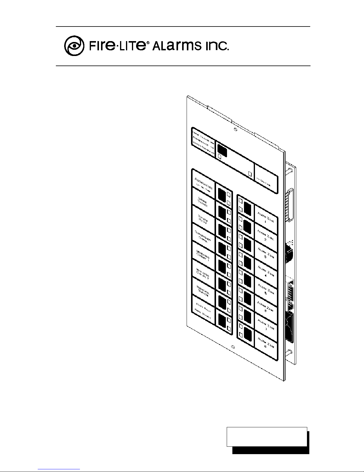
AFM-16ATX
The Annunciator Control Module-16ATX contains 16 red
alarm and 16 yellow trouble LEDs, 16 momentary touch-pad
switches for controlling each point, a system trouble LED,
an ON LINE/POWER LED, and a local piezo sounder with
a silence/acknowledge switch for audible indication of alarm
and trouble conditions at each annunciator.
AEM-16ATF
The Annunciator Expander Module-16ATF expands the
AFM-16ATX by 16 system points. The AEM-16ATF is
identical in size and in frontal appearance to the AFM16ATX. One to three of these expander modules can be
supported by an AFM-16ATX, to a maximum of 64 system
points. Note: The AEM-16ATF cannot be used to expand
the AFM-32AX.
ABM-16ATF
The Annunciator Blank Module-16ATF is a dress plate
identical in appearance to the front panel of the AFM-16ATX
and AEM-16ATF modules. The blank module is used to
cover unused module positions in an annunciator backbox.
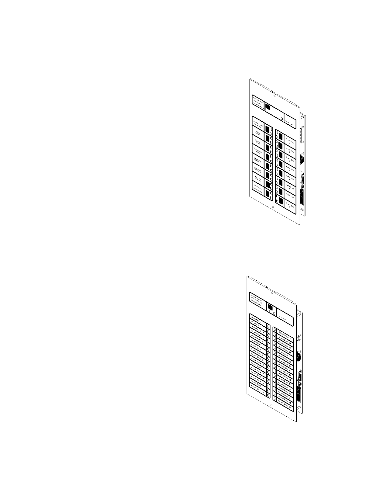
AFM-32AX
The Annunciator Control Module-32AX contains 32 red
alarm LEDs, a system trouble LED, an ON LINE/POWER
LED, and a local piezo sounder with a silence/acknowledge
switch for audible indication of alarm and trouble conditions
at each annunciator.
AEM-32AF
The Annunciator Expander Module-32AF expands the AFM32AX by 32 system points. The AEM-32AF is identical in
frontal appearance to the AFM-32AX. One expander module can be supported by an AFM-32AX, providing a maximum of 64 points. Note: The AEM-32AF cannot be used to
expand the AFM-16ATX.
ABM-32AF
The Annunciator Blank Module-32AF is a dress plate identical in appearance to the front panel of the AFM-32AX and
AEM–32AF modules. The blank module is used to cover
unused module positions in an annunciator backbox.
15390 Rev D 8/2/96 P/N 15390:D
5
Page 6
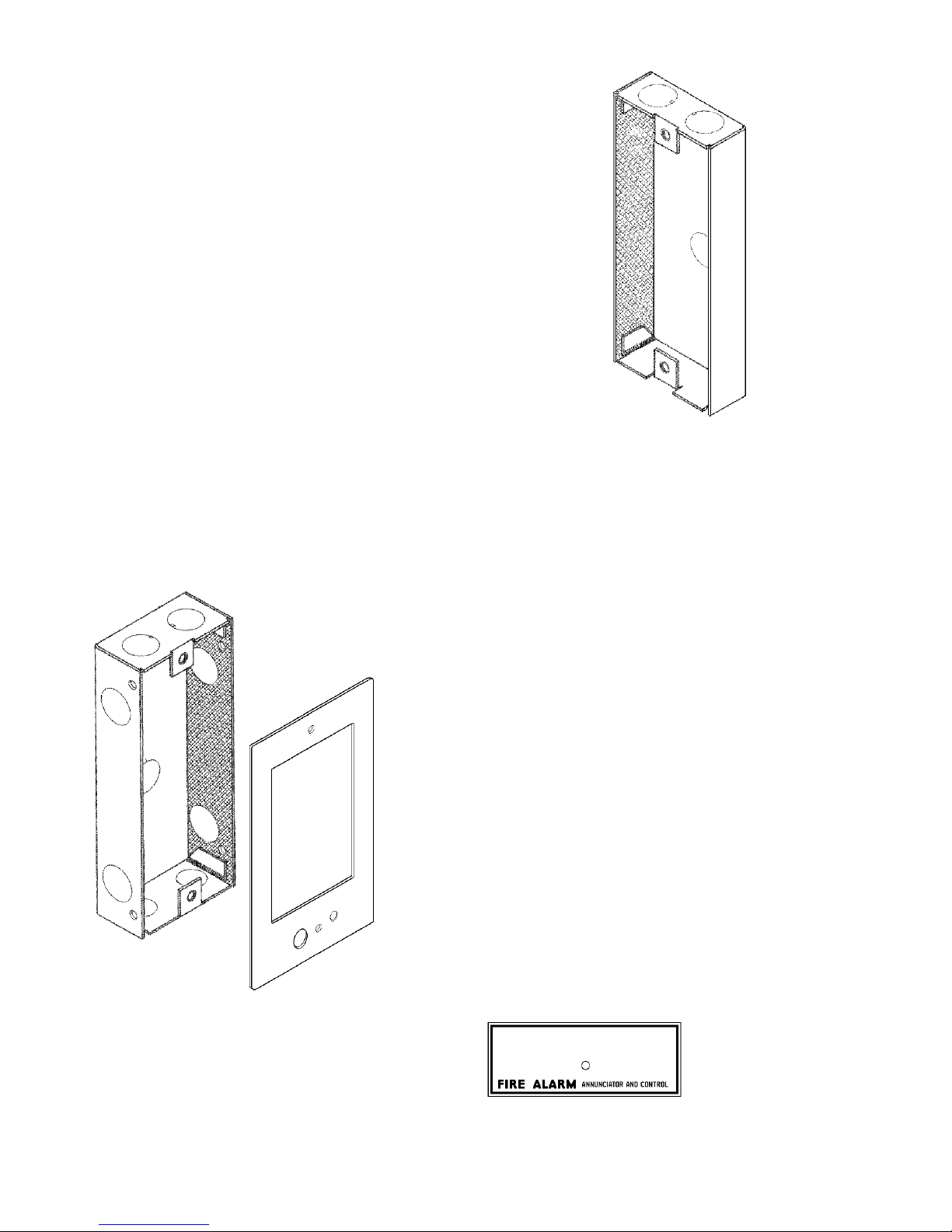
ABS-1F
The Annunciator Surface Box-1F provides for the remote mounting of a single AFM-16ATX or AFM-32AX annunciator in a surfacemount enclosure. Knockouts are provided for use with 1/2" conduit. The annunciator mounts directly to the ABS-1F without a
dress plate. (H = 8-1/2" W = 4-1/2" D = 1-3/8")
ABS-2F
(not illustrated)
The Annunciator Surface Box-2F provides for the surface mounting of one AFM-16ATX/AEM-16ATF combination or one AFM32AX/AEM-32AF combination. Knockouts are provided for use
with 1/2" conduit. The annunciator module mounts directly to the
ABS-2F without a dress plate. (H=8-1/2" W=8-15/16" D=1-3/8")
Note: The ABS-1F and ABS-2F will not support the installation of
the AKS-1F Annunciator Key Switch.
ABF-1F
The Annunciator Flush Box-1F provides for the
remote mounting of a single AFM-16ATX or
AFM-32AX annunciator in a flush-mount enclosure. Knockouts are provided for use with 1/2"
conduit. The ABF-1F includes a trim plate
(height=11" width=6-1/4"), mounting hardware,
and an adhesive-backed Annunciator Label for
the dress plate. (H = 9-15/16" W = 4-5/8" D =
2-1/2")
ABF-2F
(not illustrated)
The Annunciator Flush Box-2F provides for the
flush mounting of one AFM-16ATX/AEM-16ATF
combination or one AFM-32AX/AEM-32AF combination. Includes a trim plate (H=11" W=10-5/
8") and adhesive-backed Annunciator Label.
(H=9-15/16" W=9-3/16" D=2-1/2")
6
Annunciator Label
15390 Rev D 8/2/96 P/N 15390:D
Page 7
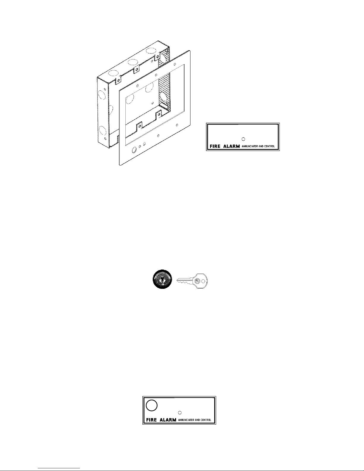
Annunciator Label
ABF-4F
The Annunciator Flush Box-4F provides for the remote mounting of one to four
AFM-16ATX/AEM-16ATF modules. Knockouts are provided for use with 1/2"
conduit. The flush-mounted ABF-4F includes a trim plate (H=11" W=19-3/8")
and an Annunciator Label. (H=9 - 15/16" W=17 - 3/8" D=2 - 1/2")
AKS-1F
The Annunciator Key Switch-1F provides access security for the control switches
on the AFM-16ATX. The key switch kit includes a key and hardware for mounting
to the trim plate of one of the flush-mount type annunciator enclosures. Also
included is an adhesive-backed Annunciator Label for use with the key switch/
dress plate assembly.
Note: The AKS-1F can only be employed with a flush-mount type backbox.
Annunciator Label
15390 Rev D 8/2/96 P/N 15390:D
7
Page 8
Section Three:
Design Considerations
Limits
Up to 32 annunciators may be installed on an EIA-485 circuit. The actual number of
annunciator modules may be larger depending on the number of expander modules
employed.
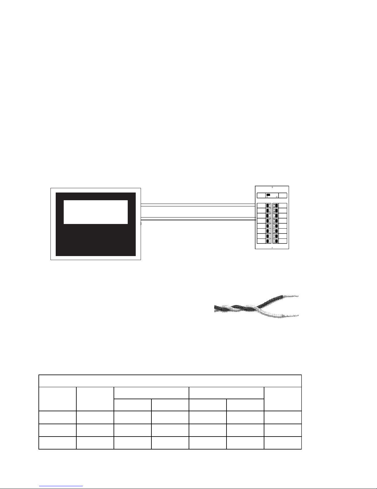
Wire Runs
Communication between the Control Panel and the annunciator is accomplished over a
power-limited two-wire EIA-485 serial interface. This communication, including the
wiring, is supervised by the fire alarm control panel. Power for the annunciators is
provided via a separate power-limited power loop from the control panel which is
inherently supervised (loss of power also results in a communication failure at the control
panel).
Fire Alarm Control Panel
Annunciator Power
(14 to 18 AWG )
Two-wire EIA-485 Circuit
(Maximum of 6,000 feet)
Annunciator
Wiring Specifications
The EIA-485 circuit cannot be T-Tapped; it must be wired in a continuous fashion from
the control panel to the annunciator. The maximum wiring distance between the
panel and the last annunciator is 6,000 feet @ 16 AWG.
The wiring size must be a 14 AWG to 18 AWG twisted
shielded pair cable having a Characteristic Impedance of
120 ohms, +/- 20%. Limit the total wire resistance to 100 ohms on the EIA485 circuit, and 10 ohms on the annunciator power circuit. Do not run cable adjacent to,
or in the same conduit as, 120 volts AC service, noisy electrical circuits that are powering
mechanical bells or horns, audio circuits above 25 volts (RMS), motor control circuits, or
SCR power circuits. Twisted-shielded wiring should be used for EIA-485 circuits that are
not contained entirely in conduit.
STANDARD ANNEALED COPPER WIRE
Wire Size
A.W.G.
14 64 4110 0.00323 2.58 2.97 12.4
16 51 2580 0.00203 4.09 4.73 7.82
18 40 1620 0.00128 6.51 7.51 4.92
Diameter in
Mils
Circ. Mils Sq. Inch @ 77 F. @ 149 F.
Table 3-1: Typical Wire Resistance Chart
8
Cross Section Ohms per 1000 ft.
15390 Rev D 8/2/96 P/N 15390:D
Pounds per
1000 ft.
Page 9
5
5
5
5
1234
1234
1234
1234
1234
1234
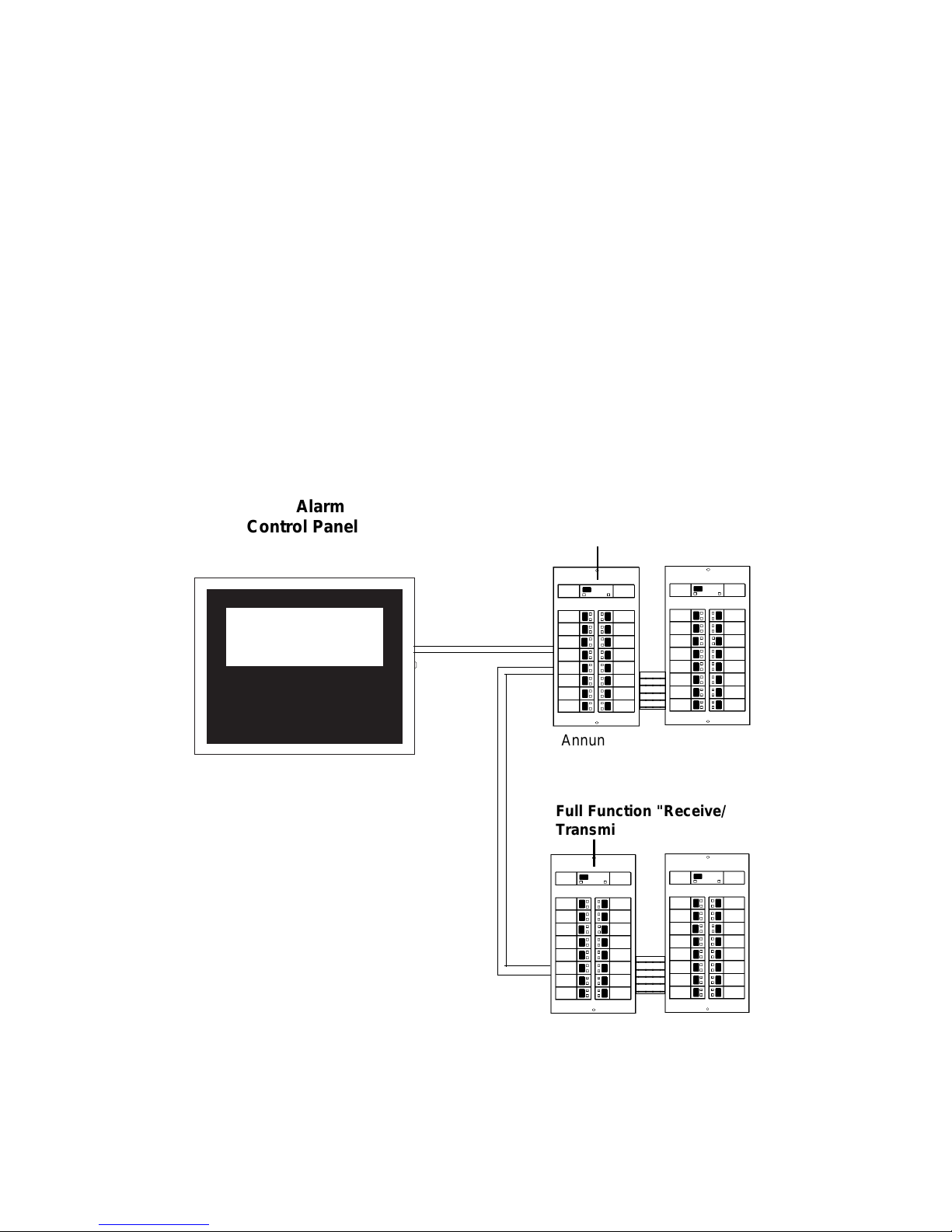
Receive Only Annunciators
For redundant annunciation of system points, annunciators can be configured as
"Receive Only" annunciators. Receive Only annunciators are not fully supervisable.
Receive Only annunciators intercept information being transmitted to a "Receive/
Transmit" annunciator so that information can be duplicated at an intermediate display
location. When configured for Receive Only operation, they cannot send information to
the system, therefore they cannot perform remote functions such as Acknowledge,
Silence, or Reset. Control switches on Receive Only annunciators can be used only for
local functions, such as lamp test. Wiring to Receive Only annunciators may be
supervised by installing the modules "upstream" of fully-supervised Receive/Transmit
annunciators along the EIA-485 line.
Receive/Transmit Annunciators
Annunciators that are configured to serve as full function annunciators can both receive
status information as well as transmit commands to the control panel. This allows the
annunciator to remotely execute functions of the control panel in addition to displaying the
status of the system.
Fire Alarm
Control Panel
Two-wire
EIA-485
Circuit
"Receive Only" Annunciator
Annunciator Expander
Full Function "Receive/
Transmit"
234
234
234
234
15390 Rev D 8/2/96 P/N 15390:D
Annunciator Expander
9
Page 10

Electrical Ratings
Input Voltage: 24 volts DC (power-limited).
Current Draw from 24 volt DC Input: Standby Alarm
AFM-16ATX/AFM-32AX 0.040 amps 0.056 amps
AEM-16ATF/AEM-32AF 0.002 amps 0.018 amps
Data Communications Port: EIA-485 operating at 20 Kbaud (power-limited).
Annunciator Power Requirements
Annunciators draw their power from the control panel and must be considered when
calculating the primary and secondary power supply requirements for the system. Each
annunciator module is accounted for in the power calculations outlined in the respective
installation manual. However, if the current draw dedicated to the annunciators must be
calculated as a separate figure, use the equations below.
Column A
Number of AFM modules [ ] X 0.040 = amps
The 0.040 amps can be reduced to 0.030 for modules
with Piezo Disable or Flash Inhibit modes selected.
Number of AEM modules [ ] X 0.002 = amps
Column B
Sum Column A for Total Annunciator Standby Current = amps
Number of AFM and AEM modules assumed to be
in alarm simultaneously [ ] X 0.018 = amps
Entering the total
Number of AFM and AEM modules
in above will allow for the
simultaneous illumination of all LEDs. When the alarm system specification permits,
calculations can be based on a 10% alarm loading capacity. For 10% capacity, enter 10%
of the total number of AFM and AEM modules multiplied by the number of remote
annunciator locations, but do not enter less than one.
Sum Column B for Total Annunciator Alarm Current = amps
The Total Annunciator Alarm Current cannot exceed 200 mA from the MPS-24BF, or
1 amp from the MPS-24AF.
10
15390 Rev D 8/2/96 P/N 15390:D
Page 11

Section Four:
Annunciator Installation
Mounting the cabinet or backbox
Select an appropriate knockout on the enclosure. Mount the cabinet or backbox. Ground
the enclosure to a solid metallic ground, such as a grounded cold water pipe. Pull all
annunciator wiring into the enclosure as illustrated in Figures 1 and 2. Connect
annunciator wiring to the removable terminal blocks as illustrated in Figure 4.
Note: A 120-ohm End-of-Line Resistor (Part Number 71244 supplied with the annunciator) must be installed at the last annunciator on the EIA-485 circuit. Remove the ELRs
installed on all annunciators except the last.
Installing the annunciators
Insert the custom display labels into the annunciator and expanders (see Figure 3). Set
the dip switches on the AFM-32AX or AFM-16ATX annunciator as outlined in Section Six.
Turn the dress plate over and place down on a surface with the threaded studs facing up.
Position the AFM-32AX or AFM-16ATX annunciator over the threaded studs on the dress
plate and secure with the two nuts and lock washers provided as illustrated in Figure 5.
ABF-1F Installation Only
Remove the backing from the gummed Annunciator Label and affix the label to
the dress plate as illustrated in Figure 6. If employing an AKS-1F, mount to the
dress plate. Plug the AKS-1F switch leads to Connector J4 on the Annunciator
(see Figure 7). Plug the two annunciator terminal blocks into the annunciator.
Place the annunciator/dress plate assembly into the backbox and secure with
two screws.
Annunciator installation in an ABF-1F is complete.
ABF-2F/ABF-4F Installation Only
Remove the backing from the gummed Annunciator Label and affix the label to
the dress plate as illustrated in Figure 7. If employing an AKS-1F, mount to the
dress plate. Plug the AKS-1F switch leads to Connector J4 on the Annunciator.
Installing the expanders
Plug one end of an Annunciator Expander Ribbon Cable into Connector J2 on the AFM32AX or AFM-16ATX. Install the first AEM-16ATF or AEM-32AF expander module in the
second dress plate position. Connect the expander ribbon from the annunciator to
Connector J3 on this expander.
ABF-2F Installation Only
Plug the two annunciator terminal blocks into the AFM-16ATX or the first AFM32AX. Place the annunciator/dress plate assembly into the ABF-2F backbox.
Secure the assembly with the screws provided.
Annunciator installation in an ABF-2F is complete.
15390 Rev D 8/2/96 P/N 15390:D
11
Page 12

Completing expander connections
AFM-16ATX/AEM-16ATF
Installation Only
If installing one AFM-16ATX with three
AEM-16ATF expanders in the same dress
plate, perform the following installation
steps:
Connect one end of an expander ribbon
to Connector J2 on the first expander.
Install the second AEM-16ATF expander
in the third dress plate position. Connect
the other end of the expander ribbon
from the first expander to Connector J3
on the second expander.
Connect one end of a ribbon cable to
Connector J2 on the second expander.
Install the third AEM-16ATF expander in
the fourth dress plate position. Connect
the other end of the ribbon cable from the
second expander to Connector J3 on the
third expander.
Completing installation in a cabinet or an ABF-4F
Plug the two annunciator terminal blocks into the AFM-16ATX or the first AFM-32AX.
Place the annunciator/dress plate assembly into the cabinet or ABF-4F backbox. Secure
the assembly with the screws provided. Apply primary (AC) power, followed by
secondary (battery backup) power.
Programming and testing the annunciators
This completes annunciator installation. After programming the fire alarm control panel
to accept the annunciators, fully test the Annunciator Control System by ensuring that
each switch performs its intended function, that each LED lights, and that the annunciators can perform the functions outlined in the section, "Operating the Annunciator."
12
15390 Rev D 8/2/96 P/N 15390:D
Page 13
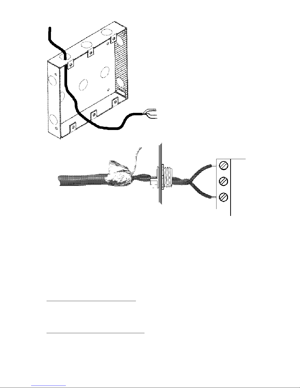
Figure 1:
Installing the Enclosure
Mount the backbox or cabinet and pull all annunciator wiring into the enclosure.
Enclosure
Annunciator
Figure 2: Terminating the Shield
The EIA-485 circuit must be wired using a twisted-shielded pair cable having a Characteristic Impedance of 120 ohms, +/- 20%. Do not run cable adjacent to, or in the same
conduit as, 120-volt AC service, noisy electrical circuits that are powering mechanical
bells or horns, audio circuits above 25 VRMS, motor control circuits, or SCR power circuits.
All enclosures, including the FACP backbox, must be connected to earth ground! Never
use the shield for grounding purposes.
Control Panel only.
When the EIA-485 shield is in conduit: connect it to system reference (
The shield can enter the cabinet, but must be insulated from the cabinet (not electrical
contact). Between annunciators, wire-nut multiple shields together (which can be inside
of the respective enclosure, but can not contact the enclosure.)
When the EIA-485 shield is not in conduit: Terminate the shield at the outside of the FACP
backbox (ground). Do not allow the shield to enter or even touch the cabinet. Between
annunciators, wire-nut multiple shields together
Terminate the EIA-485 shield at the Fire Alarm
system common).
outside of
the respective enclosures.
15390 Rev D 8/2/96 P/N 15390:D
13
Page 14

Remove center pages for Slide-In Labels
AFM-16ATX/AEM-16ATF Labels
Two labels are required for the AFM-16ATX/AEM-16ATF - one for the left-hand side and
one for the right-hand side of each module. Each label has a distinctive format.
Set A
Factory-printed zone labels:
These slide-in annunciator labels provide for alarm zones 1
through 56. A blank label for custom labeling is also included.
Set B
Factory-printed system/zone labels:
This set provides labels for system control functions such as
Acknowledge, Signal Silence, Supervisory, and alarm zones 1
through 56.
Set C
Custom labels:
These blank labels provide for customized information by the user.
If information is to be typed onto these labels, they should be
reproduced on a copy machine so that the entire page can be
inserted into a typewriter.
Effective Window Size
The size of the visible portion of an AFM-16ATX label window is 9/
16" high by 1" across. Using a pitch of 10 characters per inch at
six lines per inch, up to three lines of 10 characters each may be
typed within this window space.
1"
9/16"
14
15390 Rev D 8/2/96 P/N 15390:D
Page 15

Remove center pages for Slide-In Labels
AFM-32AX/AEM-32AF Labels
Two labels are required for the AFM-32AX/AEM-32AF - one for the left-hand side and one
for the right-hand side of the face plate. Each label has a distinctive format.
Set E
Factory-printed zone labels:
These slide-in annunciator labels provide for alarm zones 1
through 32.
Set F
Factory-printed system/custom labels:
These slide-in annunciator labels provide for system control
functions such as Acknowledge, Signal Silence, Supervisory, and
for custom information to be entered into the remaining 56 circuits.
Set G
Factory-printed system/zone labels:
These slide-in annunciator labels provide for system control
functions such as Acknowledge, Signal Silence, Supervisory, and
for alarm zones 1 through 56.
Set H
Custom User Labels:
These blank labels can be customized by the user. If information
is to be typed onto these labels, they should be reproduced on a
copy machine so that the entire page can be inserted into a
typewriter.
Effective Window Size
The size of the visible portion of an AFM-32AX/AEM-32AF label
window is 1/2" high by 1-3/8" across. Using a pitch of 10
characters per inch at six lines per inch, up to two lines of 13
characters may be typed within this window space.
1-3/8"
1/2"
15390 Rev D 8/2/96 P/N 15390:D
15
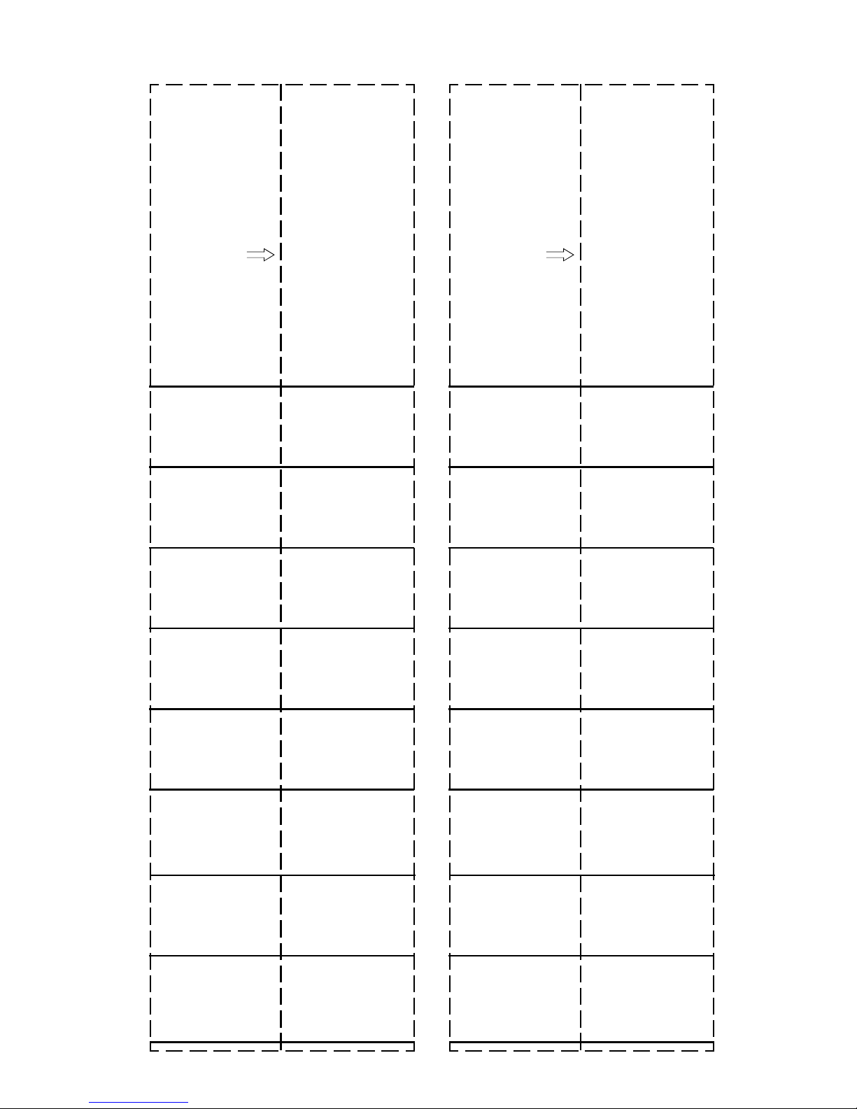
Page 16

Figure 3: Slide-In Labels
Remove the center pages of this manual. If
using the custom user display labels, type
the appropriate information on the labels.
Carefully cut out the labels and insert them
into the annunciator by slipping them into
the label slots on the back side of the
annunciator face plate.
Note: To ensure the best fit, cut directly
along the dotted line surrounding each label.
Figure 4: Terminal Wiring
• Do not "T-Tap" the EIA-485 circuit which must
be power-limited. It will not function properly.
Wire as shown below.
• Leave the 120-ohm resistor installed across
the EIA-485 Out terminals at the last annun-
ciator on the circuit (see below). Remove this
resistor from all other annunciators.
• Connect Earth Ground to a mounting screw
on the backbox or cabinet.
• Connect 24 VDC Power to the annunciator.
This power must be power-limited but need
not be supervised by a power supervision
relay since it is inherently supervised by the
control panel (loss of communications is registered during loss of power to the annunciator).
Control
Panel
First Annunciator Last Annunciator
EIA-485 In ( - )
EIA-485 Out ( - )
EIA-485 Out (+)
EIA-485 In (+)
Common In (-)
Common Out (-)
Power In (+24 VDC)
Power Out (+24 VDC)
Earth Ground
TB2
4
3
2
1
TB1
5
4
3
2
1
EIA-485 (-)
EIA-485 (+)
Wiring Multiple Annunciators (6000-ft max run)
16
-
-
TB2
+
+
15390 Rev D 8/2/96 P/N 15390:D
ELR
Part #
71244
-
-
TB2
+
+
Page 17

Figure 5: Mounting the Trim Ring
Position the annunciator over the threaded studs on
the dress plate and secure with two nuts and lock
washers provided.
AFM
Dress
Plate
Figure 6: Applying the Annunciator Label
Remove backing from adhesive-backed Annunciator Label and affix the
label to the bottom of the dress plate as illustrated.
Note: If an AKS-1F Annunciator Key Switch is to be installed, use the
label supplied with the kit.
15390 Rev D 8/2/96 P/N 15390:D
17
Page 18

Figure 7:
Annunciator Options
If employing an Annunciator Key Switch (AKS1F), mount the switch to the dress plate (ABF-1F
Dress Plate illustrated below). Plug the switch leads
from the AKS-1F into Connector J4 on the annunciator.
ABF-1F (back view)
18
15390 Rev D 8/2/96 P/N 15390:D
Page 19

Figure 8: Main Power Supply Connections
The annunciator can be powered by an MPS-24AF or an MPS-24BF. The power run to
the annunciator need not contain a Power Supervision Relay since loss of power is
inherently supervised through communication loss.
MPS-24AF Main Power Supply
Connect the power run for the AFM to MPS-24AF TB3 Terminals 1 (+) and 2 (-) (1 amp
max). The total amount of current drawn from these terminals cannot exceed that rating
in standby or in alarm.
24 VDC Power (+)
to AFM TB1-3
MPS-24AF
Common ( - )
to AFM TB1-5
MPS-24BF Main Power Supply
Connect the power run to MPS-24BF TB2 Terminals 1 (+) and 2 (-). No more than 200
mA current can be drawn from these terminals in standby or alarm.
24 VDC Power (+)
to AFM TB1-3
( - ) Common
to AFM TB1-5
MPS-24BF
15390 Rev D 8/2/96 P/N 15390:D
19
Page 20

Section Five:
Operating the Annunciators
For a complete description of annunciator operation for various specific applications,
refer to Sensiscan 2000 Manual, Document 15017.
Figure 9: Operating the AFM-16ATX
Local Silence/Acknowledge
Switch
This switch serves two purposes:
1) When pressed, it first lights all the LEDs on the
AFM-16ATX (except the On Line LED) and then
each expander and also sounds the piezo (provided it hasn't been disabled) for as long as the
switch is held down.
2) It acknowledges all status changes for both the
annunciator and the expanders. Flashing LEDs
will latch on solid and the piezo will be silenced.
On Line LED
This green indicator flashes during communication with the control panel.
System Trouble LED
This yellow indicator lights for all trouble conditions in the system (not just for those points or
zones mapped to the annunciator/expanders).
16 Annunciator Points
Note 1:
If the annunciator loses communication with the control panel, all the yellow trouble LEDs will
flash.
20
Control Switch
Functions as a local Lamp Test for the two LEDs
dedicated to a point.
Control switches can be used to execute such
system functions as ACKNOWLEDGE, SIGNAL
SILENCE, and SYSTEM RESET. Switches can
also be used to control the states of various output
circuits.
Red LED
Yellow LED
15390 Rev D 8/2/96 P/N 15390:D
Page 21

Figure 10: Operating the AEM-16ATF
Lamp Test Switch
When pressed, it lights all the LEDs on the AEM16ATF expander (except the On Line LED).
These LEDs are not functional on expanders.
Control Switch
Functions as a local Lamp Test for the two LEDs
dedicated to this point.
Control switches can be used to execute such
system functions as ACKNOWLEDGE, SIGNAL
SILENCE, and SYSTEM RESET. Switches can
also be used to control the states of various
output circuits.
Red LED
Yellow LED
16 Expander Points
Note 1:
If the annunciator loses communication with the control panel, all the yellow trouble LEDs will
flash.
Note 2:
Simultaneous manual activation of the two switches in any row of the annunciator or an expander will cause the state of all the points on that module to
change state.
15390 Rev D 8/2/96 P/N 15390:D
One row
21
Page 22

Figure 11: Operating the AFM-32AX
This switch serves two purposes:
Local Silence/Acknowledge
Switch
1) When pressed, it first lights all the LEDs on the
annunciator (except the On Line LED) then on the
expander and also sounds the piezo (provided it
hasn't been disabled) for as long as the switch is
held down.
2) It acknowledges all status changes for the
AFM-32AX. Flashing LEDs will latch on solid and
the piezo will be silenced.
On Line LED
This green indicator flashes during communication with the control panel.
System Trouble LED
This yellow indicator lights for all trouble conditions in the system (not just for those points or
zones mapped to the annunciator).
32 Annunciator Points
If the annunciator loses communication with the
control panel, the yellow System Trouble LED will flash.
22
Red Alarm LED
15390 Rev D 8/2/96 P/N 15390:D
Page 23

Figure 12: Operating the AEM-32AF
Lamp Test Switch
When pressed, it lights all the LEDs on the
expander (except the On Line LED).
These LEDs are not functional on expanders.
32 Annunciator Points
15390 Rev D 8/2/96 P/N 15390:D
Red Alarm LED
23
Page 24

Section Six:
Annunciators and the Sensiscan 2000
Capabilities
When installed with a Sensiscan 2000, an annunciator can annunciate the status of
initiating and notification circuits, relays, and several system control functions. Each
annunciator LED is automatically assigned to one and only one system point:
Circuits: IZ-8F, IZ-4F Initiating Device Circuits (alarm and trouble)
IC-4F/ICE-4F Notification Appliance Circuits (trouble)*
CR-4F/CRE-4F Control Relays (trouble)*
TC-2F circuits (trouble)*
TC-4F circuits (trouble)*
* Indication of output circuit activation can be obtained by programming the CPU for
"OUTPUT STATUS."
System Acknowledge
Controls: Signal Silence
System Reset
Activate Notification Circuits 1 and 2, the Remote Signalling
Municipal Tie circuit, and the Alarm Relay.
System Trouble Indication
Communication between the CPU and the Annunciator Control System is accomplished
over a two-wire EIA-485 serial interface. This communication circuit is supervised by the
FACP. Loss of communication results in "System Trouble" and "Module Failure"
indications at the FACP CPU.
Installation Requirements
The EIA-485 circuit that drives the annunciator must be connected to the CPU as
illustrated below.
Supervised and Power-limited
EIA-485 (-)
to AFM TB2 Terminal # 4
(+) EIA-485
to AFM TB2 Terminal # 1
Figure 13: Connecting the EIA-485 Loop
24
15390 Rev D 8/2/96 P/N 15390:D
Page 25

Installing Modules in the Sensiscan 2000:
The annunciator begins annunciation with the CPU and continues with the annunciation
of circuits on the module installed directly after the CPU. To ensure full employment of
annunciator points, mount Sensiscan 2000 modules that require annunciation in the CPU
row first, then in the second row, etc. Modules with circuits that need not be annunciated
by the AFM should be installed further down in the cabinet.
Note that without invoking the Eight-Point-Shift, the first eight points
would be dedicated to CPU functions, not circuits off of the first
module.
15390 Rev D 8/2/96 P/N 15390:D
25
Page 26

Figure 14: Configuring Annunciators for Sensiscan 2000
DIP switches must be set before the annunciator will operate properly.
Annunciator Key Switch
(AKS-1) Connector
DOWN POSITION = ON
DIP Switch
DIP Switch settings:
1. Not Used: This switch must be set "OFF".
None One Two Three
UP (OPEN) = OFF
DIP Switch
2. Expanders Installed: OFF ON OFF ON
3. Expanders Installed: OFF OFF ON ON
4. Eight-Point Shift: Set switch "ON" to shift the CPU functions from the first eight annunciator
positions to expander positions 57-64.
5. Receive Only: Set this switch "ON" for each annunciator that will provide the same information
as another annunciator in a different location (when two or more annunciators hold the same address,
all but one must be configured as "Receive Only" annunciators).
6. Piezo Disable: Set this switch "ON" to disable the piezo from sounding for any event.
7. Switch Inhibit: To disable the point control switches on the annunciator from executing system
control functions, set this switch "ON." When inhibited, the switches will serve as local Lamp Test
switches only. In addition, the Acknowledge/Lamp Test switch will function only in a local capacity,
unrecognized by the System.
Note: For Canadian applications, when annunciator point control
switches are enabled (Switch 7 'OFF'), the AKS-1F or a similar listed enclosure must be employed.
8. Flash Inhibit: Set this switch "ON" to disable the flashing of LEDs associated with unacknowledged events.
Flash Inhibit also disables the piezo from sounding.
26
15390 Rev D 8/2/96 P/N 15390:D
Page 27

Annunciator Operation
Annunciator points "track" or follow those system points they are programmed to
annunciate; they do not latch. Table 6-1 outlines the annunciation of various System
circuits and functions. Note: Control Switches marked "not used" will still function as local
LAMP TEST or local ACKNOWLEDGE switches for their respective points.
Table 6-1: Annunciator Point Functions
AFM-16ATX & AEM-16ATF
M
O
Circuit Type
IZ-8F circuit
IC-4F/ICE-4F circuit
D
U
L
CR-4F/CRE-4F circuit
E
S
C
P
U
2
0
0
TC-2F, TC-4F
VC-4F, DC-4F circuit
ANNUNCIATOR
POINT # 1
ANNUNCIATOR
POINT # 2
ANNUNCIATOR
POINT # 3
ANNUNCIATOR
POINT # 4
ANNUNCIATOR
POINT # 5
ANNUNCIATOR
POINT # 6
1
0
ANNUNCIATOR
POINT # 7
ANNUNCIATOR
POINT # 8
AFM-32AX
& AEM-32AF
Red LED
Indicates alarm
status of circuit
Indicates Activation
Indicates Activation
Indicates Activation
Indicates
System Alarm
not used
not used
not used
Indicates that Notification
Circuit 1 has been activated
Indicates that Notification
Circuit 2 has been activated
Indicates that the Remote
Signalling Municipal Tie
has been activated
Indicates that
the Alarm Relay
has been
activated
Yellow LED
3
Indicates trouble
status of circuit
Indicates trouble
status of circuit
Indicates trouble
status of relay
Indicates trouble
status of relay
System Trouble
Indicates that signals
have been silenced
Supervisory condition
Indicates trouble
status of circuit
Indicates trouble
status of circuit
Indicates trouble
status of circuit
Module Trouble,
Power Failure or
Disabled Circuit(s)
Indicates
not used
Indicates
Indicates
Control Switch
not used
Control
Notification Circuit
Controls
Relays
Remote Switch
Functions
Functions as an
ACKNOWLEDGE
Functions as a
SIGNAL SILENCE
Functions as a
SYSTEM RESET
not used
Controls Notification
Circuit 1
Controls Notification
Circuit 2
Controls
Remote Signalling
Municipal Tie
Controls
Alarm Relay
2
1 If the Eight-Point Shift (DIP switch # 4) is set "ON", the eight CPU functions will be shifted from
annunciator points 1 thru 8 to points 57 thru 64 (provided those points exist in the system).
2 These control switches are active only if all of these conditions are set:
a) Receive Only (DIP Switch # 5) is set to "OFF." b) Switch Inhibit (DIP Switch # 7) is set to "OFF."
3 If an IZ-8F or IZ-4F circuit is programmed on the system as a supervisory point,
yellow LEDs will be illuminated for a supervisory condition. Illumination of the yellow LED alone
indicates a trouble condition (open circuit) on the IZ-8F supervisory circuit.
4 If a UDACT-F is employed on a system with an annunciator, point assignments for the first eight
yellow LEDs on the annunciator will change. Refer to the UDACT-F Manual and the appropriate
FACP Manual.
15390 Rev D 8/2/96 P/N 15390:D
both
the red and
27
Page 28

28
15390 Rev D 8/2/96 P/N 15390:D
Page 29

Set A
Label 1
LOCAL SILENCE AND
ACKNOWLEDGE
Set A
Label 2
Set A
Label 3
LAMP TEST
Set A
Label 4
SYSTEM TROUBLE
Cut out along dotted line
and insert into the lefthand side of AFM-16ATX
ALARM ZONE
1
ALARM ZONE
2
ALARM ZONE
3
ALARM ZONE
4
ON-LINE
Cut out along dotted line
and insert into the righthand side of AFM-16ATX
ALARM ZONE
9
ALARM ZONE
10
ALARM ZONE
11
ALARM ZONE
12
Cut out along dotted line
and insert into the lefthand side of AEM-16ATF
ALARM ZONE
17
ALARM ZONE
18
ALARM ZONE
19
ALARM ZONE
20
Cut out along dotted line
and insert into the righthand side of AEM-16ATF
ALARM ZONE
25
ALARM ZONE
26
ALARM ZONE
27
ALARM ZONE
28
ALARM ZONE
5
ALARM ZONE
6
ALARM ZONE
7
ALARM ZONE
8
ALARM ZONE
13
ALARM ZONE
14
ALARM ZONE
15
ALARM ZONE
16
ALARM ZONE
21
ALARM ZONE
22
ALARM ZONE
23
ALARM ZONE
24
ALARM ZONE
29
ALARM ZONE
30
ALARM ZONE
31
ALARM ZONE
32
Page 30

Set E
Label 1
Set E
Label 2
Set F
Label 1
LOCAL SILENCE AND
ACKNOWLEDGE
SYSTEM TROUBLE SYSTEM TROUBLE
Cut out along dotted line
and insert into the lefthand side of AFM-32AX
ALARM ZONE 1
ALARM ZONE 2
ALARM ZONE 3
ALARM ZONE 4
ALARM ZONE 5
ALARM ZONE 6
ON-LINE
Cut out along dotted line
and insert into the righthand side of AFM-32AX
ALARM ZONE 17
ALARM ZONE 18
ALARM ZONE 19
ALARM ZONE 20
ALARM ZONE 21
ALARM ZONE 22
LOCAL SILENCE AND
ACKNOWLEDGE
Cut out along dotted line
and insert into the lefthand side of AFM-32AX
SYSTEM ALARM
IND. CIRCUIT 1
ND. CIRCUIT 2
I
ALARM ZONE 7
ALARM ZONE 8
ALARM ZONE 9
ALARM ZONE 10
ALARM ZONE 11
ALARM ZONE 12
ALARM ZONE 13
ALARM ZONE 14
ALARM ZONE 15
ALARM ZONE 16
ALARM ZONE 23
ALARM ZONE 24
ALARM ZONE 25
ALARM ZONE 26
ALARM ZONE 27
ALARM ZONE 28
ALARM ZONE 29
ALARM ZONE 30
ALARM ZONE 31
ALARM ZONE 32
UNICIPAL TIE
M
ALARM RELAY
ALARM ZONE 1
ALARM ZONE 2
ALARM ZONE 3
ALARM ZONE 4
ALARM ZONE 5
ALARM ZONE 6
ALARM ZONE 7
ALARM ZONE 8
Page 31
Set A
Label 5
Set A
Label 6
Set A
Label 7
Set A
Label 8
LAMP TEST
Cut out along dotted line
and insert into the lefthand side of AEM-16ATF
ALARM ZONE
33
ALARM ZONE
34
ALARM ZONE
35
Cut out along dotted line
and insert into the righthand side of AEM-16ATF
ALARM ZONE
41
ALARM ZONE
42
ALARM ZONE
43
LAMP TEST
Cut out along dotted line
and insert into the lefthand side of AEM-16ATF
ALARM ZONE
49
ALARM ZONE
50
ALARM ZONE
51
Cut out along dotted line
and insert into the righthand side of AEM-16ATF
ALARM ZONE
36
ALARM ZONE
37
ALARM ZONE
38
ALARM ZONE
39
ALARM ZONE
40
ALARM ZONE
44
ALARM ZONE
45
ALARM ZONE
46
ALARM ZONE
47
ALARM ZONE
48
ALARM ZONE
52
ALARM ZONE
53
ALARM ZONE
54
ALARM ZONE
55
ALARM ZONE
56
Page 32

Set F
Label 2
ON-LINE
Set F
Label 3
LAMP TEST
Set F
Label 4
Cut out along dotted line
and insert into the righthand side of AFM-32AX
Cut out along dotted line
and insert into the lefthand side of AFM-32AX
Cut out along dotted line
and insert into the righthand side of AFM-32AX
Page 33

Set B
Label 1
LOCAL SILENCE AND
ACKNOWLEDGE
Set B
Label 2
Set B
Label 3
LAMP TEST
Set B
Label 4
SYSTEM TROUBLE
Cut out along dotted line
and insert into the lefthand side of AFM-16ATX
ACKNOWLEDGE
System Alarm/Trouble
SIGNAL
SILENCE
SYSTEM
RESET
SUPERVISORY
SIGNAL
ON-LINE
Cut out along dotted line
and insert into the righthand side of AFM-16ATX
ALARM ZONE
1
ALARM ZONE
2
ALARM ZONE
3
ALARM ZONE
4
Cut out along dotted line
and insert into the lefthand side of AEM-16ATF
ALARM ZONE
9
ALARM ZONE
10
ALARM ZONE
11
ALARM ZONE
12
Cut out along dotted line
and insert into the righthand side of AEM-16ATF
ALARM ZONE
17
ALARM ZONE
18
ALARM ZONE
19
ALARM ZONE
20
INDICATING
CIRCUIT 1
INDICATING
CIRCUIT 2
MUNICIPAL
STATION
ALARM RELAY
PANEL TROUBLE
ALARM ZONE
5
ALARM ZONE
6
ALARM ZONE
7
ALARM ZONE
8
ALARM ZONE
13
ALARM ZONE
14
ALARM ZONE
15
ALARM ZONE
16
ALARM ZONE
21
ALARM ZONE
22
ALARM ZONE
23
ALARM ZONE
24
Page 34

Set G
Label 1
LOCAL SILENCE AND
ACKNOWLEDGE
Set G
Label 2
Set G
Label 3
LAMP TEST
SYSTEM TROUBLE
Cut out along dotted line
and insert into the lefthand side of AFM-32AX
SYSTEM ALARM
IND. CIRCUIT 1
ND. CIRCUIT 2
I
UNICIPAL TIE
M
ON-LINE
Cut out along dotted line
and insert into the righthand side of AFM-32AX
ALARM ZONE 9
ALARM ZONE 10
ALARM ZONE 11
ALARM ZONE 12
ALARM ZONE 13
ALARM ZONE 14
ALARM ZONE 15
Cut out along dotted line
and insert into the lefthand side of AEM-32AF
ALARM ZONE 25
ALARM ZONE 26
ALARM ZONE 27
ALARM ZONE 28
ALARM ZONE 29
ALARM ZONE 30
ALARM ZONE 31
ALARM RELAY
ALARM ZONE 1
ALARM ZONE 2
ALARM ZONE 3
ALARM ZONE 4
ALARM ZONE 5
ALARM ZONE 6
ALARM ZONE 7
ALARM ZONE 8
ALARM ZONE 16
ALARM ZONE 17
ALARM ZONE 18
ALARM ZONE 19
ALARM ZONE 20
ALARM ZONE 21
ALARM ZONE 22
ALARM ZONE 23
ALARM ZONE 24
ALARM ZONE 32
ALARM ZONE 33
ALARM ZONE 34
ALARM ZONE 35
ALARM ZONE 36
ALARM ZONE 37
ALARM ZONE 38
ALARM ZONE 39
ALARM ZONE 40
Page 35

Set B
Label 5
Set B
Label 6
Set B
Label 7
Set B
Label 8
LAMP TEST
Cut out along dotted line
and insert into the lefthand side of AEM-16ATF
ALARM ZONE
25
ALARM ZONE
26
ALARM ZONE
27
Cut out along dotted line
and insert into the righthand side of AEM-16ATF
ALARM ZONE
33
ALARM ZONE
34
ALARM ZONE
35
LAMP TEST
Cut out along dotted line
and insert into the lefthand side of AEM-16ATF
ALARM ZONE
41
ALARM ZONE
42
ALARM ZONE
43
Cut out along dotted line
and insert into the righthand side of AEM-16ATF
ALARM ZONE
49
ALARM ZONE
50
ALARM ZONE
51
ALARM ZONE
28
ALARM ZONE
29
ALARM ZONE
30
ALARM ZONE
31
ALARM ZONE
32
ALARM ZONE
36
ALARM ZONE
37
ALARM ZONE
38
ALARM ZONE
39
ALARM ZONE
40
ALARM ZONE
44
ALARM ZONE
45
ALARM ZONE
46
ALARM ZONE
47
ALARM ZONE
48
ALARM ZONE
52
ALARM ZONE
53
ALARM ZONE
54
ALARM ZONE
55
ALARM ZONE
56
Page 36

Set G
Label 4
Cut out along dotted line
and insert into the righthand side of AEM-32AF
ALARM ZONE 41
ALARM ZONE 42
ALARM ZONE 43
ALARM ZONE 44
ALARM ZONE 45
ALARM ZONE 46
ALARM ZONE 47
ALARM ZONE 48
ALARM ZONE 49
ALARM ZONE 50
ALARM ZONE 51
ALARM ZONE 52
ALARM ZONE 53
ALARM ZONE 54
ALARM ZONE 55
ALARM ZONE 56
Page 37

Set C
Label 1
LOCAL SILENCE AND
ACKNOWLEDGE
Set C
Label 2
Set C
Label 3
LAMP TEST
Set C
Label 4
SYSTEM TROUBLE
Cut out along dotted line
and insert into the lefthand side of AFM-16ATX
ON-LINE
Cut out along dotted line
and insert into the righthand side of AFM-16ATX
Cut out along dotted line
and insert into the lefthand side of AEM-16ATF
Cut out along dotted line
and insert into the righthand side of AEM-16ATF
Page 38

Set H
Label 4
Set H
Label 5 (extra)
LOCAL SILENCE AND
ACKNOWLEDGE
Set H
Label 6 (extra)
Cut out along dotted line
and insert into the righthand side of AEM-32AF
SYSTEM TROUBLE
Cut out along dotted line
and insert into the lefthand side of AFM-32AX
ON-LINE
Cut out along dotted line
and insert into the righthand side of AFM-32AX
Page 39

Set C
Label 5
Set C
Label 6
Set C
Label 7
Set C
Label 8
LAMP TEST
Cut out along dotted line
and insert into the lefthand side of AEM-16ATF
Cut out along dotted line
and insert into the righthand side of AEM-16ATF
LAMP TEST
Cut out along dotted line
and insert into the lefthand side of AEM-16ATF
Cut out along dotted line
and insert into the righthand side of AEM-16ATF
Page 40

Set H
Label 1
LOCAL SILENCE AND
ACKNOWLEDGE
Set H
Label 2
Set H
Label 3
LAMP TEST
SYSTEM TROUBLE
Cut out along dotted line
and insert into the lefthand side of AFM-32AX
ON-LINE
Cut out along dotted line
and insert into the righthand side of AFM-32AX
Cut out along dotted line
and insert into the lefthand side of AEM-32AX
Page 41

Limited W arranty
Fire-Lite® warrants its products to be free from defects in materials and w orkmanship
for eighteen (18) months from the date of manufacture, under normal use and
service. Products are date stamped at time of manufacture . The sole and exclusive
obligation of Fire-Lite
and labor, any part which is defective in materials or workmanship under normal
use and service. For products not under Fire-Lite
control, the warranty is eighteen (18) months from date of original purchase by
®
Fire-Lite
's distributor unless the installation instructions or catalog sets for th a
shorter period, in which case the shorter period shall apply. This warranty is void if
the product is altered, repaired or serviced by anyone other than Fire-Lite
authorized distributors or if there is a failure to maintain the products and systems
in which they operate in a proper and workable manner. In case of defect, secure
a Return Material A uthorization f orm from our customer service department. Return
product, transportation prepaid, to Fire-Lite
Connecticut 06472-1653.
®
is to repair or replace, at its option, free of charge for parts
®
manufacturing date-stamp
®
or its
®
, 12 Clintonville Road, Northford,
This writing constitutes the only warranty made by Fire-Lite
®
products. Fire-Lite
does not represent that its products will prevent any loss by
®
with respect to its
fire or otherwise, or that its products will in all cases provide the protection for
®
which they are installed or intended. Buyer acknowledges that Fire-Lite
is not an
insurer and assumes no risk for loss or damages or the cost of any inconvenience,
transportation, damage, misuse, abuse, accident or similar incident.
Fire-Lite
®
GIVES NO WARRANTY, EXPRESSED OR IMPLIED, OF
MERCHANTABILITY, FITNESS FOR ANY PARTICULAR PURPOSE, OR
OTHERWISE WHICH EXTEND BEYOND THE DESCRIPTION ON THE FACE
HEREOF. UNDER NO CIRCUMSTANCES SHALL Fire-Lite
®
BE LIABLE FOR ANY
LOSS OF OR DAMAGE TO PROPERTY, DIRECT, INCIDENTAL OR
CONSEQUENTIAL, ARISING OUT OF THE USE OF, OR INABILITY TO USE
®
Fire-Lite
PRODUCTS. FUR THERMORE, Fire-Lite® SHALL NOT BE LIABLE FOR
ANY PERSONAL INJURY OR DEATH WHICH MAY ARISE IN THE COURSE OF,
OR AS A RESUL T OF, PERSONAL, COMMERCIAL OR INDUSTRIAL USE OF ITS
PRODUCTS.
This warranty replaces all previous warranties and is the only warranty made by
Fire-Lite
®
. No increase or alteration, written or verbal, of the obligation of this
warranty is authorized.
"Fire-Lite" is a registered trademark.
Technical Publishing Document WARFSM-C.PM6 04/02/96
12 Clintonville Road,
Nor thford, CT 06472
Phone: (203) 484-7161
FAX: (203) 484-7118
 Loading...