

Page 1

Fire Alarm Communicator
411UDAC
Manual
Document 51073
9/20/2013 Rev:
P/N 51073:E ECN 13-786
E
Page 2

Fire Alarm & Emergency Communication System Limitations
While a life safety system may lower insurance rates, it is not a substitute for life and property insurance!
An automatic fire alarm system—typically made up of smoke
detectors, heat detectors, manual pull stations, audible warning
devices, and a fire alarm control panel (FACP) with remote notification capability—can provide early warning of a developing fire.
Such a system, however, does not assure protection against
property damage or loss of life resulting from a fire.
An emergency communication system—typically made up of
an automatic fire alarm system (as described above) and a life
safety communication system that may include an autonomous
control unit (ACU), local operating console (LOC), voice communication, and other various interoperable communication methods—can broadcast a mass notification message. Such a
system, however, does not assure protection against property
damage or loss of life resulting from a fire or life safety event.
The Manufacturer recommends that smoke and/or heat
detectors be located throughout a protected premises following
the recommendations of the National Fire Protection Association
Standard 72 (NFPA 72), manufacturer's recommendations, State
and local codes, and the recommendations contained in the
Guide for Proper Use of System Smoke Detectors, which is
made available at no charge to all installing dealers. This
document can be found at http://www.systemsensor.com/
appguides/. A study by the Federal Emergency Management
Agency (an agency of the United States government) indicated
that smoke detectors may not go off in as many as 35% of all
fires. While fire alarm systems are designed to provide early
warning against fire, they do not guarantee warning or protection
against fire. A fire alarm system may not provide timely or
adequate warning, or simply may not function, for a variety of
reasons:
Smoke detectors may not sense fire where smoke cannot
reach the detectors such as in chimneys, in or behind walls, on
roofs, or on the other side of closed doors. Smoke detectors
also may not sense a fire on another level or floor of a building.
A second-floor detector, for example, may not sense a first-floor
or basement fire.
Particles of combustion or “smoke” from a developing fire
may not reach the sensing chambers of smoke detectors
because:
• Barriers such as closed or partially closed doors, walls, chimneys, even wet or humid areas may inhibit particle or smoke
flow.
• Smoke particles may become “cold,” stratify, and not reach
the ceiling or upper walls where detectors are located.
• Smoke particles may be blown away from detectors by air
outlets, such as air conditioning vents.
• Smoke particles may be drawn into air returns before reaching the detector.
The amount of “smoke” present may be insufficient to alarm
smoke detectors. Smoke detectors are designed to alarm at various levels of smoke density. If such density levels are not created by a developing fire at the location of detectors, the
detectors will not go into alarm.
Smoke detectors, even when working properly, have sensing
limitations. Detectors that have photoelectronic sensing chambers tend to detect smoldering fires better than flaming fires,
which have little visible smoke. Detectors that have ionizing-type
sensing chambers tend to detect fast-flaming fires better than
smoldering fires. Because fires develop in different ways and
are often unpredictable in their growth, neither type of detector is
necessarily best and a given type of detector may not provide
adequate warning of a fire.
Smoke detectors cannot be expected to provide adequate warning of fires caused by arson, children playing with matches
(especially in bedrooms), smoking in bed, and violent explosions
(caused by escaping gas, improper storage of flammable materials, etc.).
Heat detectors do not sense particles of combustion and alarm
only when heat on their sensors increases at a predetermined
rate or reaches a predetermined level. Rate-of-rise heat detectors may be subject to reduced sensitivity over time. For this
reason, the rate-of-rise feature of each detector should be tested
at least once per year by a qualified fire protection specialist.
Heat detectors are designed to protect property, not life.
IMPORTANT! Smoke detectors must be installed in the same
room as the control panel and in rooms used by the system for
the connection of alarm transmission wiring, communications,
signaling, and/or power. If detectors are not so located, a developing fire may damage the alarm system, compromising its ability to report a fire.
Audible warning devices such as bells, horns, strobes,
speakers and displays may not alert people if these devices
are located on the other side of closed or partly open doors or
are located on another floor of a building. Any warning device
may fail to alert people with a disability or those who have
recently consumed drugs, alcohol, or medication. Please note
that:
• An emergency communication system may take priority over
a fire alarm system in the event of a life safety emergency.
• Voice messaging systems must be designed to meet intelligibility requirements as defined by NFPA, local codes, and
Authorities Having Jurisdiction (AHJ).
• Language and instructional requirements must be clearly disseminated on any local displays.
• Strobes can, under certain circumstances, cause seizures in
people with conditions such as epilepsy.
• Studies have shown that certain people, even when they hear
a fire alarm signal, do not respond to or comprehend the
meaning of the signal. Audible devices, such as horns and
bells, can have different tonal patterns and frequencies. It is
the property owner's responsibility to conduct fire drills and
other training exercises to make people aware of fire alarm
signals and instruct them on the proper reaction to alarm signals.
• In rare instances, the sounding of a warning device can cause
temporary or permanent hearing loss.
A life safety system will not operate without any electrical
power. If AC power fails, the system will operate from standby
batteries only for a specified time and only if the batteries have
been properly maintained and replaced regularly.
Equipment used in the system may not be technically compatible with the control panel. It is essential to use only equipment
listed for service with your control panel.
Telephone lines needed to transmit alarm signals from a premises to a central monitoring station may be out of service or temporarily disabled. For added protection against telephone line
failure, backup radio transmission systems are recommended.
The most common cause of life safety system malfunction is
inadequate maintenance. To keep the entire life safety system in
excellent working order, ongoing maintenance is required per the
manufacturer's recommendations, and UL and NFPA standards. At a minimum, the requirements of NFPA 72 shall be followed. Environments with large amounts of dust, dirt, or high air
velocity require more frequent maintenance. A maintenance
agreement should be arranged through the local manufacturer's
representative. Maintenance should be scheduled monthly or as
required by National and/or local fire codes and should be performed by authorized professional life saftety system installers
only. Adequate written records of all inspections should be kept.
Limit-D-1-2013
2 411UDAC Manual — P/N 51073:E 9/20/2013
Page 3

Installation Precautions
Adherence to the following will aid in problem-free installation with long-term reliability:
WARNING - Several different sources of power can be
connected to the fire alarm control panel. Disconnect all
sources of power before servicing. Control unit and associated equipment may be damaged by removing and/or inserting cards, modules, or interconnecting cables while the unit is
energized. Do not attempt to install, service, or operate this
unit until manuals are read and understood.
CAUTION - System Re-acceptance Test after Software
Changes: To ensure proper system operation, this product
must be tested in accordance with NFPA 72 after any programming operation or change in site-specific software. Reacceptance testing is required after any change, addition or
deletion of system components, or after any modification,
repair or adjustment to system hardware or wiring. All components, circuits, system operations, or software functions known
to be affected by a change must be 100% tested. In addition,
to ensure that other operations are not inadvertently affected,
at least 10% of initiating devices that are not directly affected
by the change, up to a maximum of 50 devices, must also be
tested and proper system operation verified.
This system meets NFPA requirements for operation at 0-49º
C/32-120º F and at a relative humidity . However, the useful
life of the system's standby batteries and the electronic components may be adversely affected by extreme temperature
ranges and humidity. Therefore, it is recommended that this
system and its peripherals be installed in an environment with
a normal room temperature of 15-27º C/60-80º F.
Verify that wire sizes are adequate for all initiating and indicating device loops. Most devices cannot tolerate more than a
10% I.R. drop from the specified device voltage.
Like all solid state electronic devices, this system may
operate erratically or can be damaged when subjected to lightning induced transients. Although no system is completely
immune from lightning transients and interference, proper
grounding will reduce susceptibility. Overhead or outside aerial
wiring is not recommended, due to an increased susceptibility
to nearby lightning strikes. Consult with the Technical Services Department if any problems are anticipated or encountered.
Disconnect AC power and batteries prior to removing or
inserting circuit boards. Failure to do so can damage circuits.
Remove all electronic assemblies prior to any drilling, filing,
reaming, or punching of the enclosure. When possible, make
all cable entries from the sides or rear. Before making modifications, verify that they will not interfere with battery, transformer, or printed circuit board location.
Do not tighten screw terminals more than 9 in-lbs. Overtightening may damage threads, resulting in reduced terminal
contact pressure and difficulty with screw terminal removal.
This system contains static-sensitive components.
Always ground yourself with a proper wrist strap before handling any circuits so that static charges are removed from the
body. Use static suppressive packaging to protect electronic
assemblies removed from the unit.
Follow the instructions in the installation, operating, and programming manuals. These instructions must be followed to
avoid damage to the control panel and associated equipment.
FACP operation and reliability depend upon proper installation.
Precau-D1-9-2005
FCC Warning
WARNING: This equipment generates, uses, and can
radiate radio frequency energy and if not installed and
used in accordance with the instruction manual may
cause interference to radio communications. It has been
tested and found to comply with the limits for class A
computing devices pursuant to Subpart B of Part 15 of
FCC Rules, which is designed to provide reasonable
protection against such interference when devices are
operated in a commercial environment. Operation of this
equipment in a residential area is likely to cause interference, in which case the user will be required to correct
the interference at his or her own expense.
Canadian Requirements
This digital apparatus does not exceed the Class A limits
for radiation noise emissions from digital apparatus set
out in the Radio Interference Regulations of the Canadian Department of Communications.
Le present appareil numerique n'emet pas de bruits radioelectriques depassant les limites applicables aux appareils numeriques de la classe A prescrites dans le
Reglement sur le brouillage radioelectrique edicte par le
ministere des Communications du Canada.
HARSH™, NIS™, and NOTI•FIRE•NET™ are all trademarks; and Acclimate® Plus, ECLIPSE®, Filtrex®, FlashScan®, NION®, NOTIFIER®, ONYX®,
ONYXWorks®, Pinnacle®, UniNet®, VeriFire®, and VIEW® are all registered trademarks of Honeywell International Inc. Echelon® is a registered
trademark and LonWorks™ is a trademark of Echelon Corporation. ARCNET® is a registered trademark of Datapoint Corporation. Microsoft® and
Windows® are registered trademarks of the Microsoft Corporation.
©2013. All rights reserved. Unauthorized use of this document is strictly prohibited.
411UDAC Manual — P/N 51073:E 9/20/2013 3
Page 4

Software Downloads
In order to supply the latest features and functionality in fire alarm and life safety technology to our customers, we make
frequent upgrades to the embedded software in our products. To ensure that you are installing and programming the latest
features, we strongly recommend that you download the most current version of software for each product prior to
commissioning any system. Contact Technical Support with any questions about software and the appropriate version for a
specific application.
Documentation Feedback
Your feedback helps us keep our documentation up-to-date and accurate. If you have any comments or suggestions about our
online Help or printed manuals, you can email us.
Please include the following information:
•Product name and version number (if applicable)
•Printed manual or online Help
•Topic Title (for online Help)
•Page number (for printed manual)
•Brief description of content you think should be improved or corrected
•Your suggestion for how to correct/improve documentation
Send email messages to:
FireSystems.TechPubs@honeywell.com
Please note this email address is for documentation feedback only. If you have any technical issues, please contact Technical
Services.
4 411UDAC Manual — P/N 51073:E 9/20/2013
Page 5

Table of Contents
Section 1: Product Description .............................................................................................10
1.1: Product Features ..........................................................................................................................................10
1.2: Specifications...............................................................................................................................................12
1.3: Circuits.........................................................................................................................................................13
1.3.1: Channels/Inputs .................................................................................................................................13
1.3.2: Notification Appliance Circuit ..........................................................................................................13
1.3.3: Output Circuits ..................................................................................................................................13
1.3.4: Auxiliary Relays................................................................................................................................13
1.3.5: Earth Ground .....................................................................................................................................13
1.4: Controls and Indicators................................................................................................................................14
1.5: Components and Accessories ......................................................................................................................15
1.6: Digital Communicator Operation ................................................................................................................15
1.7: Panel Configuration .....................................................................................................................................16
1.8: Operational Modes.......................................................................................................................................16
1.8.1: Normal Mode.....................................................................................................................................16
1.8.2: Real Time Clock Mode......................................................................................................................16
1.8.3: Program Mode ...................................................................................................................................16
1.8.4: Troubleshoot Mode............................................................................................................................16
1.8.5: Default Mode.....................................................................................................................................16
1.9: Telephone Requirements and Warnings.......................................................................................................17
1.9.1: Telephone Circuitry - PH1 & PH2 ....................................................................................................17
1.9.2: Digital Alarm Communicator:...........................................................................................................17
1.9.3: Telephone Company Rights and Warnings .......................................................................................17
Section 2: Installation.............................................................................................................18
2.1: Mounting Options........................................................................................................................................18
2.2: Mounting......................................................................................................................................................18
2.3: Operating Power ..........................................................................................................................................20
Primary Power Source (AC) and Earth Ground Connections ..............................................................20
Secondary Power Source (batteries).....................................................................................................21
2.4: Input Channels .............................................................................................................................................22
2.5: Output Circuits.............................................................................................................................................25
Notification Appliance Circuit .............................................................................................................25
Relay Programming..............................................................................................................................26
2.6: Telephone Circuits .......................................................................................................................................27
2.7: Optional Programmer ..................................................................................................................................28
2.8: UL Power-limited Wiring Requirements.....................................................................................................29
Section 3: Modes of Operation.............................................................................................. 30
3.1: Normal Mode...............................................................................................................................................30
3.1.1: Programmer Key Functions...............................................................................................................31
MODE KEY .........................................................................................................................................31
LAMP TEST KEY ...............................................................................................................................31
1st EVENT KEY ..................................................................................................................................32
DOWN ARROW..................................................................................................................................32
UP ARROW .........................................................................................................................................32
ENTER/STORE ...................................................................................................................................32
3.1.2: Programmer Display..........................................................................................................................32
3.2: Password Creation and Entry.......................................................................................................................32
3.3: Real Time Clock Mode................................................................................................................................33
3.4: Program Mode .............................................................................................................................................34
3.4.1: DACT Programming .........................................................................................................................36
Primary Central Station Phone Number (00 - 19)................................................................................36
Primary Central Station Number Communication Format (20) ...........................................................36
Event Codes - Setting Entries...............................................................................................................37
411UDAC Manual — P/N 51073:E 9/20/2013 5
Page 6

Table of Contents
Ademco Contact ID Format Primary Central Station Event Codes .....................................................37
4+2 Standard and 4+2 Express Formats Primary Central Station Event Codes...................................38
All 3+1, 4+1 and 4+2 Expanded Formats Primary Central Station Event Codes ................................39
Primary Central Station Number Account Code (21 - 24) ...................................................................40
Primary Central Station Number 24 Hour Test Time (25 - 28)............................................................40
Primary Central Station Number 24/12/8/6 Hour Test Time Interval (29) ..........................................40
Secondary Central Station Phone Number (30 - 49) ............................................................................40
Secondary Central Station Number Communication Format (50) .......................................................41
Ademco Contact ID Format Secondary Central Station Event Codes .................................................42
4+2 Standard and 4+2 Express Formats Secondary Central Station Event Codes...............................43
All 3+1, 4+1 and 4+2 Expanded Formats Secondary Central Station Event Codes ............................44
Secondary Central Station Number Account Code (51 - 54) ...............................................................45
Secondary Central Station Number 24 Hour Test Time (55 - 58)........................................................45
Secondary Central Station Number 24/12/8/6 Hour Test Time Interval (59) ......................................45
AC Loss Reporting Delay (60).............................................................................................................45
Backup Reporting (61) .........................................................................................................................45
Reserved for Future Use (62) ...............................................................................................................45
DACT Trouble Reminder (63) .............................................................................................................45
Operational Mode Selection (64)..........................................................................................................45
Input Channel 1 Function Selection (65)..............................................................................................46
Input Channel 2 Function Selection (66)
Input Channel 3 Function Selection (67)
Input Channel 4 Function Selection (68)
Input Channel 1 Delay Timer (69 - 71) ................................................................................................46
Input Channel 2 Delay Timer (72 - 74)
Input Channel 3 Delay Timer (75 - 77) ................................................................................................47
Input Channel 4 Delay Timer (78 - 80)
1
............................................................................................46
1
............................................................................................46
1
............................................................................................46
2
...............................................................................................46
1
...............................................................................................47
Touchtone/Rotary Select for Primary Phone (81) ................................................................................47
Make/Break Ratio for Primary Phone (82)...........................................................................................47
Touchtone/Rotary Select for Secondary Phone (83) ............................................................................47
Make/Break Ratio for Secondary Phone (84).......................................................................................47
Output Relay #1 Enable (85) ................................................................................................................47
Output Relay #1 Function Selections (86)............................................................................................47
Output Relay #2 Enable (87) ................................................................................................................47
Output Relay #2 Function Selections (88)............................................................................................47
Reserved for Future Use (89) ...............................................................................................................48
Panel Unlock (90).................................................................................................................................48
Alarm Verification Enable (91)............................................................................................................48
Silence Inhibit Notification Appliance Circuit (92) .............................................................................48
Autosilence Notification Appliance Circuit (93)..................................................................................48
Restoral Method (94)............................................................................................................................49
Coding, Notification Appliance Circuit (95)........................................................................................50
Trouble Call Limit - Dialer Runaway Prevention (96).........................................................................50
Panel Identification Number (97 - 100)................................................................................................50
Service Terminal 1 Phone Number (101 - 120)....................................................................................51
Ring Count on Primary Phone Line (121 - 122)...................................................................................51
FAX/Answer Machine, Primary Phone Line (123)..............................................................................51
Service Terminal 2 Phone Number (124 - 143)....................................................................................51
Upload/Download Reports Sent to Secondary Central Station Phone #, Backup or Always (144).....51
Programming Event Code Settings (145 - 312)....................................................................................51
3.5: Default Mode ...............................................................................................................................................51
3.6: Troubleshoot Mode......................................................................................................................................52
Channel/Inputs......................................................................................................................................52
AC Line ................................................................................................................................................52
Notification Appliance Circuit .............................................................................................................52
Telephone Line Testing ........................................................................................................................53
6 411UDAC Manual — P/N 51073:E 9/20/2013
Page 7

Table of Contents
Section 4: Central Station Communications........................................................................ 54
4.1: Transmittal Priorities ...................................................................................................................................57
4.2: Ademco Contact ID Format Event Code Description .................................................................................57
Section 5: Remote Site Upload/Download............................................................................60
5.1: General.........................................................................................................................................................60
5.1.1: Security Features ...............................................................................................................................61
Secret Code Verification ......................................................................................................................61
Panel Unlock ........................................................................................................................................61
Time-out at 411UDAC.........................................................................................................................61
Callback to Service Terminal ...............................................................................................................62
Error Checking .....................................................................................................................................62
Central Station Acknowledge...............................................................................................................62
Data Protection/Integrity ......................................................................................................................62
5.2: Downloading to the Communicator.............................................................................................................62
5.3: Uploading From the Communicator ............................................................................................................62
5.4: Simultaneous Data Transfers.......................................................................................................................63
Section 6: Battery Calculations............................................................................................. 64
6.1: 411UDAC Power Supply.............................................................................................................................65
Appendix A: Programming Sheets........................................................................................66
A.1: Digital Communicator Options Program Sheets ........................................................................................66
A.2: Digital Communicator Options Program Sheet (Factory Defaults)............................................................68
Appendix B: Event Codes/Transmission Format Programming Sheets ........................... 70
B.1: 4+2 Standard & 4+2 Express Formats Primary Central Station .................................................................70
B.2: 4+2 Standard & 4+2 Express Formats Secondary
B.3: 4+2 Standard & 4+2 Express Formats Primary
B.4: 4+2 Standard & 4+2 Express Formats Secondary
B.5: All 3+1, All 4+1 and 4+2 Expanded Formats for Primary
B.6: All 3+1, All 4+1 and 4+2 Expanded Formats for Secondary
B.7: All 3+1, All 4+1 and 4+2 Expanded Formats for Primary
B.8: All 3+1, All 4+1 and 4+2 Expanded Formats for Secondary
B.9: Ademco Contact ID Format Primary
B.10: Ademco Contact ID Format Secondary
B.11: Ademco Contact ID Format Primary
B.12: Ademco Contact ID Format Secondary
Central Station.................................................................................73
Central Station...........................................................................73
Central Station (Factory Defaults).................................................74
Central Station (Factory Defaults).............................................74
Central Station .............................................................70
Central Station .................................................................71
Central Station .............................................................71
Central Station ................................................72
Central Station ............................................72
Central Station (Factory Defaults)..................72
Central Station (Factory Defaults).............72
Appendix C: Ademco Contact ID Format Event Code Description.................................... 75
Appendix D: Events and Default Event Codes.....................................................................79
Appendix E: Operational Modes............................................................................................80
Index......................................................................................................................................... 81
411UDAC Manual — P/N 51073:E 9/20/2013 7
Page 8

This digital communicator/transmitter has been designed to comply with standards set forth by the
following regulatory agencies:
• Underwriters Laboratories
• NFPA National Fire Protection Association
Before proceeding, the installer should be familiar with the following documents.
NFPA Standards
Central Station Signaling Systems Protected Premises Unit (Automatic, Manual and
Waterflow)
Proprietary Fire Alarm Systems (Protected Premises Unit)
Remote Station Fire Alarm Systems
Automatic Fire Detectors
Installation, Maintenance and Use of Notification Appliances for Fire Alarm Systems
Inspection, Testing and Maintenance for Fire Alarm Systems
Underwriters Laboratories Documents:
UL 217 Smoke Detectors, Single and Multiple Station
UL 268 Smoke Detectors for Fire Protective Signaling Systems
UL 346 Waterflow Indicators for Fire Protective Signaling Systems
UL 464 Audible Signaling Appliances
UL 521 Heat Detectors for Fire Protective Signaling Systems
UL 864 Standard for Control Units for Fire Protective Signaling Systems
UL 1481 Power Supplies for Fire Protective Signaling Systems
UL 1635 Digital Alarm Communicator System Units
UL 1638 Visual Signaling Appliances
UL 1971 Signaling Devices for Hearing Impaired
Other:
NEC Article 250 Grounding
NEC Article 300 Wiring Methods
NEC Article 760 Fire Protective Signaling Systems
Applicable Local and State Building Codes
Requirements of the Local Authority Having Jurisdiction (LAHJ)
This product has been certified to comply with the requirements in the Standard for Control Units
and Accessories for Fire Alarm Systems, UL 864, 9th Edition. Operation of this product with products not tested for UL 864, 9th Edition has not been evaluated. Such operation requires the
approval of the local Authority Having Jurisdiction (AHJ).
8 411UDAC Manual — P/N 51073:E 9/20/2013
Page 9
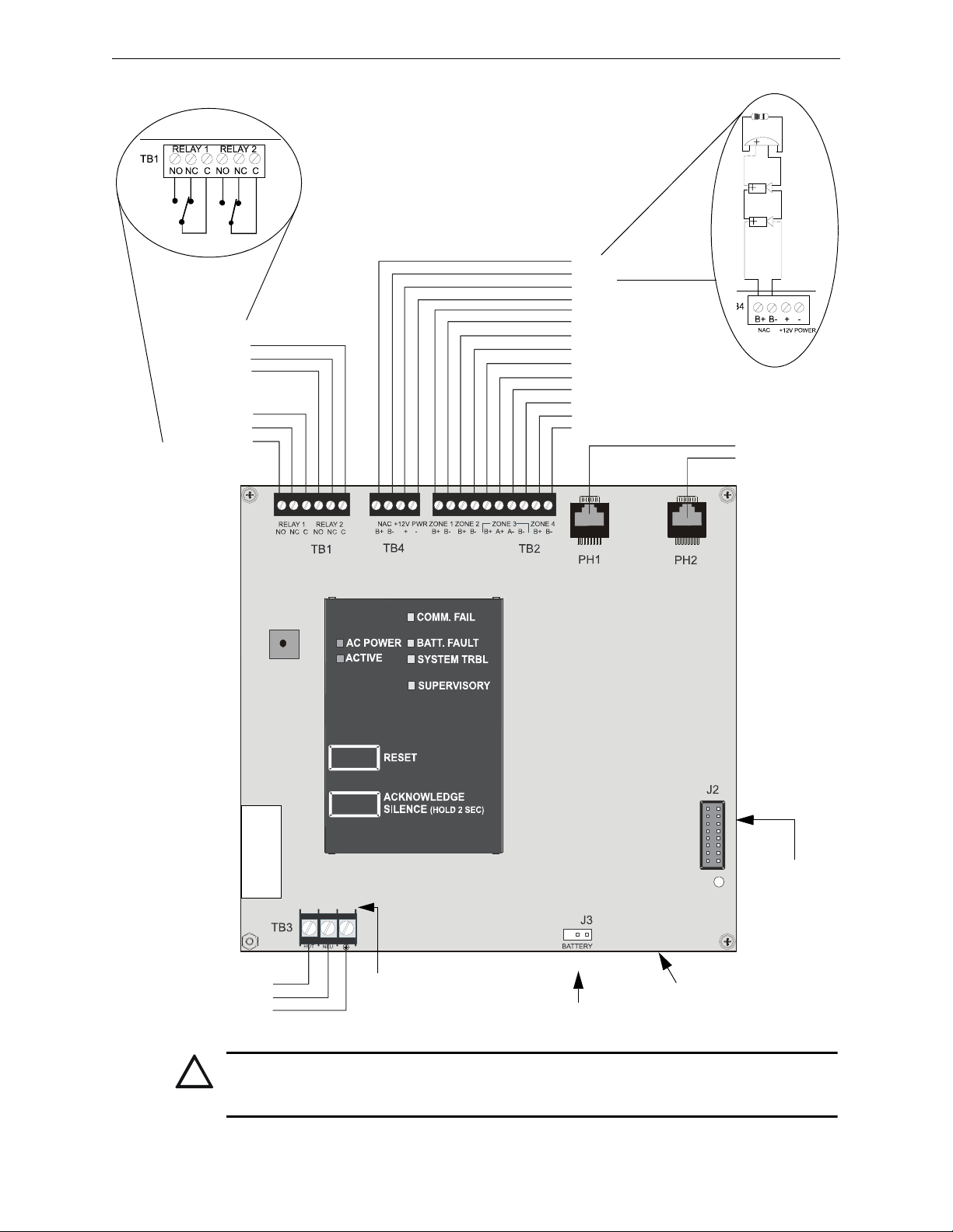
CAUTION!
GND FAULT
411UDAC-PCB Rev
Relay 2
(nonsupervised)
Common
NC Contact
NO Contact
Relay 1
(nonsupervised)
Common
NC Contact
NO Contact
NAC B+
NAC B+12 VDC Resettable
- Resettable (common)
Zone 1 B+
Zone 1 BZone 2 B+
Zone 2 BZone 3 B+
Zone 3 A+
Zone 3 AZone 3 BZone 4 B+
Zone 4 B-
Phone Line 1
Phone Line 2
PRO-411
DACT
Programmer
Battery Connector
(supervised, nonpower-limited)
AC Power Connector*
(supervised, nonpower-limited)
HOT
NEU
EARTH
411udab2.wmf
411anac.wmf
411arel.wmf
- +
HIGH VOLTAGE
CAUTION!
Transformer
Connection
All Circuits on TB2 and TB4 are
supervised and power-limited
hinged cover must be
closed after wiring
411UDAC Board Revision Level
!
411UDAC Manual — P/N 51073:E 9/20/2013 9
CAUTION: AC POWER TERMINAL LAYOUT CHANGE
USE CAUTION WHEN WIRING AC POWER TO THE 411UDAC AS TERMINAL LAYOUT HAS
CHANGED ON TB3!!
Page 10
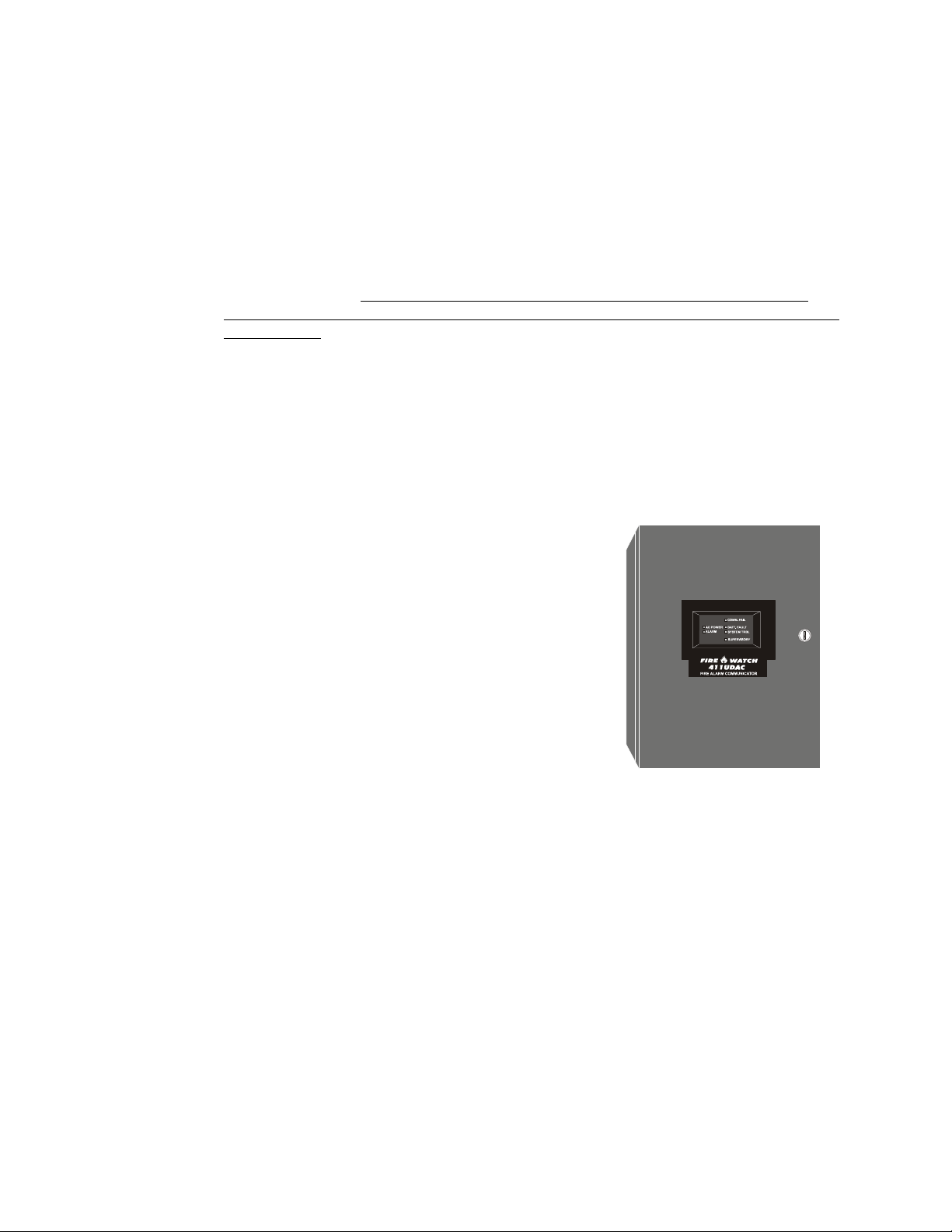
Section 1: Product Description
Figure 1.1 411UDAC Digital
Communicator
411udacv.wmf
The 411UDAC is a fire alarm communicator with four input/channels and dual telephone lines.
The four inputs use conventional input devices. The 411UDAC accepts waterflow devices, fourwire smoke detectors, pull stations and other normally-open contact devices. The unit also supervises AC voltage, telephone line input voltage/current, battery level and battery charger operation.
Outputs include one supplementary NAC (Notification Appliance Circuit), two programmable
Form-C relays and 12 VDC resettable special application power. The 411UDAC interfaces with
the public switched telephone network and is compatible with most central station receivers. A
total of fifteen popular communications formats are supported, including the industry standard
Ademco Contact ID. The communicator also contains a unique DACT option that eliminates
'dialer runaway'. It restricts the transmission of any intermittent nuisance fault to 10 attempts in a
24 hour period.
Accessories include the Fire-Watch 411 Series DACT Programmer (Model PRO-411) as well as the
PK-411UD Windows
®
-based remote site programming software. The 411UDAC is supplied with
a compact metal cabinet.
The digital communicator can be programmed or interrogated off-site via the public switched telephone network. Any IBM compatible personal computer with Windows
1200 baud Hayes
®
compatible modem and Upload/Download software P/N PK-411UD, may serve
®
XP or greater, with a
as a service terminal.
1.1 Product Features
• Four input/channels - three fixed Style B (Class B) and
one Style A (Class A) or Style B (Class B)
• Programmable input channels
4-wire smoke (Inputs 1 & 3 only)
pull station
normally-open contact
host panel trouble (Slave Mode)
supervisory
supervisory autoresettable
waterflow (silenceable)
waterflow (nonsilenceable)
• One Style Y (Class B) NAC (supplementary application)
• Dual telephone lines
Dual telephone line voltage detect
Alternating phone lines for 24 hour test messages
• 12 VDC operation
• Alarm Verification
• Signal Silence Inhibit
• Autosilence
• Trouble Reminder
• Trouble Resound - troubles will resound the buzzer every 24 hours at midnight until the
trouble is cleared
• Optional TR-6 Series Trim Ring
• 20-digit central station and service terminal telephone numbers
• NAC coding per ANSI S-3.41 (Temporal Coding)
10 411UDAC Manual — P/N 51073:E 9/20/2013
Page 11

Product Features Product Description
• Separate external keypad and display
provides means of programming 411UDAC in program mode
provides means of testing input/output circuits (including telephone connections) in
Troubleshoot Mode
• Compact in size 14.5" (36.83 cm) high X 12.875" (32.7 cm) wide X 4.5" (11.43 cm) deep
metal cabinet
• Communicates vital status of monitored control panel (Slave Mode):
fire alarm
host control panel trouble
fire supervisory
AC (mains) power loss (programmable)
other
• Communicates vital status of 411UDAC:
digital communicator troubles
telephone Line 1 and 2 voltage fault
Primary Central Station number communication fault
Secondary Central Station number communication fault
system off-normal (local Program Mode entered)
24 Hour normal test
24 Hour abnormal test (24 hour test message with previously reported alarm or trouble still
active)
• Individual LEDs for:
AC Power
System Trouble
Input Active
Supervisory
Communication Fail
Battery Trouble
Earth Fault
• Local piezo sounder with separate and distinct sounds for the various conditions
• Acknowledge/System Silence switch - 1st press silences local piezo sounder, 2nd press
silences NAC
• Reset switch
• Real time clock
• Two Form-C relays, fully programmable to activate for the following conditions:
fire alarm total communication failure
host control panel trouble DACT trouble (factory default for relay)
fire supervisory (latching)
fire supervisory (autoresettable)
• Optional PK-411UD Remote Upload/Download Kit
• 'Dialer runaway' feature
• User selectable restoral methods
411UDAC Manual — P/N 51073:E 9/20/2013 11
Page 12

Product Description Specifications
1.2 Specifications
AC Power - TB3
120 VAC, 60 Hz, 0.7 amps
Wire size: minimum 14 AWG (2.00 mm
Supervised, nonpower-limited
Battery (lead acid only) - J3
Maximum Charging Circuit: Float charge - 13.6V @ 3.15 amps
Maximum Charger Capacity: 14 Amp Hour battery
Supervised, nonpower-limited
Channels/Inputs - TB2 Terminals 1 through 10
Programmable Channels 1 through 4
Power-limited circuitry
Fully supervised (monitored for opens, shorts and earth fault)
Normal Operating Voltage: 12.0 VDC (ripple = 100 mV maximum)
End-of-Line Resistor: 2.2K ohms, ½ watt (P/N 27070 UL listed)
Operation for each channel:
• Channel/Input 1, Style B (Class B) 4-wire smoke detector input and Channel/Input 3, Style B
(Class B) 4-wire smoke detectors or waterflows or Style D (Class A) waterflow input:
Connecting 4-wire detectors on Channel/Input 3 requires NFPA Style B (Class B) only.
Alarm Current: 11 mA
Short Circuit Current: 24 mA maximum
Maximum Detector Current in Standby: 1.8 mA
Maximum Loop Resistance: 30 ohms
Detector Loop Current is sufficient to ensure operation of a minimum of one alarmed
detector per zone
Standby Current: 5.17 mA (including End-of-Line Resistor)
• Channel/Input 2 and Channel/Input 4 - Style B (Class B) contact closure input:
Short Circuit Current: 4.46 mA maximum
Maximum Loop Resistance: 100 ohms
Standby Current: 2.66 mA
Refer to the Device Compatibility Document for listed compatible devices.
Notification Appliance Circuit - TB4 Terminals 1(+) & 2(-)
The 411UDAC Notification Appliance Circuit may only be used to supplement host panel
NACs
Style Y (Class B) power-limited and supervised circuit (monitored for opens, shorts, and earth
fault)
Maximum voltage drop in wiring: 2.0 VDC
Operating voltage nominal 13.8 VDC
Current for all external devices: 1.0 amp
End-of-line resistor: 2.2K ohms, ½ watt (P/N 27070)
Refer to the Device Compatibility Document for listed compatible devices
Two Form-C Relays - TB1 Terminals 1 through 6
2
) with 600V insulation
Operating voltage nominal 12 VDC
Contact rating: 2.0 amps @ 30 VDC (resistive) or 0.5 amps @ 30 VAC (resistive)
Non-supervised
12 VDC Resettable Special Application Power - TB4 Terminals 3(+) and 4(-)
Operating voltage nominal 12 volts
Maximum ripple voltage: 10 mV
RMS
Up to 200 mA is available for powering 4-wire smoke detectors
Power-limited and supervised with a UL-listed power supervision relay
For power supply and battery calculations, refer to Section 6.
12 411UDAC Manual — P/N 51073:E 9/20/2013
Page 13

Circuits Product Description
1.3 Circuits
The 411UDAC circuit board contains a MicroController Unit (MCU), dual modular phone line
jacks, piezo sounder, and connectors for input, output and power wiring. A piezo silence switch
and reset switch are provided on the membrane panel which plugs into connector J7 on the main
circuit board.
1.3.1 Channels/Inputs
Four input channels are provided on the 411UDAC. The 411UDAC can be used to monitor a host
FACP (Fire Alarm Control Panel) in Slave Mode or as a stand-alone FAC (Fire Alarm Communicator). Each input can be programmed to monitor the following conditions:
• fire alarm activation
• 4-wire smoke (channels 1 & 3 only)
• pull station
• normally open contact device
• waterflow
• trouble activation
• fire supervisory activation
1.3.2 Notification Appliance Circuit
One Style B NAC (Notification Appliance Circuit) requiring a 2.2K ohm End-of-Line resistor.
This NAC can only be used to supplement host panel NACs.
1.3.3 Output Circuits
• Modular jacks are used to interface the primary and secondary phone lines to the public
telephone network. Phone lines are fully supervised at all times (if communication is enabled).
• 12 volt resettable special application power output (200 mA)
• 12 volt battery charger will charge up to 14 AH batteries
1.3.4 Auxiliary Relays
Two dry Form-C relays (P/N: 411RK), with contacts rated for 2.0 amps @ 30 VDC (resistive) or
0.5 amps @ 30 VAC (resistive), are installed on the main circuit board. Each relay is programma-
ble for:
Alarm
Fire supervisory - latching
Fire supervisory - autoresettable
Host panel trouble
DACT trouble
Total communications failure
1.3.5 Earth Ground
Connect a separate earth ground wire to ground stud in backbox for transient protection (refer to
Figure 2.3 on page 21 for location of stud).
411UDAC Manual — P/N 51073:E 9/20/2013 13
Page 14
Product Description Controls and Indicators
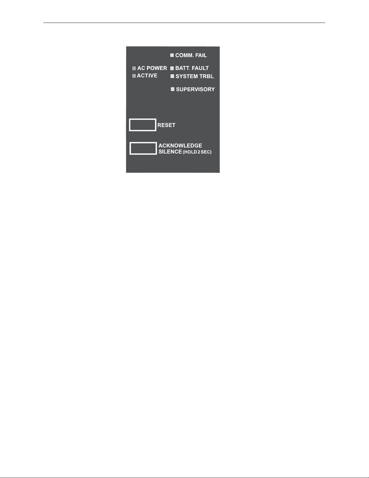
Figure 1.2 411UDAC Controls and Indicators
411udacdsp.wmf
1.4 Controls and Indicators
Front Panel Switch
• Reset Switch - to reset 411UDAC circuits
• Acknowledge/System Silence Switch
– press once to acknowledge alarm or trouble (silence local 411UDAC piezo sounder and
change all flashing LEDs to steady on)
– press a second time and hold for minimum of two seconds to perform a System Signal
Silence (silence Notification Appliance Circuit)
411UDAC Piezo Sounder
• The 411UDAC piezo sounder is used to locally annunciate DACT alarms and troubles. DACT
troubles include input channel open circuit, NAC fault, phone line 1 or 2 voltage fault, phone
number 1 or 2 communication fault and total communication failure. Separate and distinct
sounds are provided for the following conditions:
alarm - steady On
trouble - 1 second On and 1 second Off
supervisory - ½ second On and ½ second Off
Front Panel Indicator
• AC Power - green LED
• Input Active - red LED
• Communication Fail - yellow LED
• System Trouble - yellow LED
• Supervisory - yellow LED
• Battery Trouble - yellow LED
Circuit Board Indicator
• Earth Fault - yellow LED (indicates zero impedance between panel and earth ground)
14 411UDAC Manual — P/N 51073:E 9/20/2013
Page 15

Components and Accessories Product Description
1.5 Components and Accessories
Main Circuit Board
The main circuit board contains the system’s MCU (microcontroller unit), power supply, other primary components and wiring interface connectors. The main circuit board is shipped in the same
carton as the cabinet but is not mounted in the cabinet. The circuit board should be installed only
after the cabinet is mounted to the wall and the area is clean and free of potential contaminants.
Cabinet
The cabinet is red and measures 14.5" (36.83 cm) high X 12.875" (32.7 cm) wide X 4.5" (11.43 cm)
deep. It provides space for up to two 7 Amp Hour batteries which must be ordered separately. A
supplied bezel must be installed in the door opening.
Trim Ring
An optional Trim Ring (P/N TR-6-R) is available for the backbox. The Trim Ring provides a finished appearance for a semi-flush mounted panel.
Transformer Assembly
One transformer is shipped in the same carton as the cabinet and main circuit board but not
mounted in the cabinet. The transformer should be installed before the cabinet is mounted to the
wall.
Fire•Watch 411 Series DACT Programmer (Model PRO-411)
The PRO-411 is an optional DACT programmer which can be used to troubleshoot and program
the 411UDAC, as well as access the various modes of operation. The PRO-411 must be ordered
separately.
PK-411UD Upload/Download Software Kit
The optional PK-411UD Kit consists of the PK-411UD Upload/Download software on CD and the
PK-411UD Program Manual. The PK-411UD enables a user to program the 411UDAC off site via
the public switched telephone network using any personal computer with Windows
and a 1200 baud Hayes
®
compatible modem.
1.6 Digital Communicator Operation
The 411UDAC has been designed to be compatible with a wide variety of fire alarm, nonfire and
combination control panels (Slave Mode operation). Numerous formats are also available for communication to a central station. Two modular phone jacks allow easy connection to telephone lines.
Modular jacks are labeled PH1 and PH2 for the Primary and Secondary phone lines. The digital
communicator provides the following functions:
• Line Seizure- takes control phone lines, disconnecting any premise phones which may be
using the same lines
• Off/On-Hook - perform on and off-hook status to phone lines
• Listen for dial tone - 440 hertz tone typical in most networks
• Dialing the Central Station(s) phone number - default is Touch-Tone®, programmable to
rotary
• Discern proper Central Station 'ACK' and 'Kiss-off' tone(s)
• Transmit data to the Central Station(s)
• Verify data has been accepted by the Central Station(s)
• Hang-up and release phone lines
• Communicate in a variety of formats (Table 4.1, “Format Selection Addresses (20 and 50)
Programming,” on page 55).
®
XP or greater
411UDAC Manual — P/N 51073:E 9/20/2013 15
Page 16

Product Description Panel Configuration
1.7 Panel Configuration
The 411UDAC can be configured, through programming, for the following modes of operation:
• Stand-alone Mode With Communicator Enabled - the 411UDAC functions as a latching
digital alarm communicator in which all input circuit activations latch (except those
programmed as autoresettable) and are restored only by pressing the local reset switch. The
onboard communicator will attempt to transmit events to a Central Station
• Slave Mode With Communicator Enabled - the 411UDAC functions as a nonlatching slave
to a host control panel and the onboard digital alarm communicator will attempt to transmit
events to a Central Station
• Slave Mode With Communicator Disabled - the 411UDAC functions only as a nonlatching
slave to a host control panel. The digital alarm communicator will not transmit to a Central
Station
1.8 Operational Modes
1.8.1 Normal Mode
Normal Mode is the standard mode of operation in which the 411UDAC monitors the channel/input
circuits as well as telephone line voltage and other internal circuits. In addition to locally annunciating system trouble, active channel/input and communication fail, the onboard communicator
transmits system status information to UL listed central station receivers if programmed to do so.
Transmitted data includes fire alarm, fire alarm trouble, supervisory alarm and AC loss information. Specific digital communicator troubles are also transmitted.
1.8.2 Real Time Clock Mode
Real Time Clock Mode allows the user to change the digital alarm communicator’s internal 24 hour
clock. Connecting an external Programmer allows access to the various Modes of operation.
While the 411UDAC is in Real Time Clock Mode, it does not monitor channel inputs. Use of this
mode requires a valid password.
1.8.3 Program Mode
Program Mode is used to change the programmed functions of the 411UDAC. While the
411UDAC is in Program Mode, it does not monitor channel inputs. In addition, some program
items will be locked, which will prevent editing while the communicator is active (dialing, transmitting, etc.). Use of this mode requires a valid password.
1.8.4 Troubleshoot Mode
Troubleshoot Mode may be used to sample and display status for all channel/input circuits, Notification Appliance Circuit, AC power, battery, charger and 12 volt resettable power. In addition,
Troubleshoot Mode may be used for testing the telephone line interconnect wiring. Connection
from the 411UDAC’s modular jacks, through the RJ31X jacks and into the telephone network may
be easily checked. In this mode, the Programmer keypad acts similar to a telephone touchpad.
While the 411UDAC is in Troubleshoot Mode, it does not monitor channel inputs.
1.8.5 Default Mode
Default Mode may be used to return all 411UDAC programming back to the factory default settings and to reset the Real-Time Clock to ‘00:01’ midnight. See “Default Mode” on page 51.
16 411UDAC Manual — P/N 51073:E 9/20/2013
Page 17

Telephone Requirements and Warnings Product Description
1.9 Telephone Requirements and Warnings
1.9.1 Telephone Circuitry - PH1 & PH2
AC Ringer Equivalence Number (REN) = 0.4B
Mates with RJ31X Male Connector
Supervision Threshold: less than 5.0 volts for 2 minutes
The REN is used to determine the quantity of devices which may be connected to the telephone
line. Excessive RENs on the telephone line may result in the devices not ringing in response to an
incoming call. In most, but not all areas, the sum of the RENs should not exceed five (5.0). To be
certain of the number of devices that may be connected to the line, as determined by the total
RENs, contact the telephone company to determine the maximum REN for the calling area.
1.9.2 Digital Alarm Communicator:
Before connecting the 411UDAC to the public switched telephone network, the installation of two
RJ31X jacks is necessary. The following information is provided if required by the local telephone
company:
Manufacturer: Fire•Lite Alarms Inc./Notifier
One Fire-Lite Place
Northford, CT 06472
Product Model Number: 411UDAC
FCC Registration Number: 1W6AL04B411UDAC
AC Ringer Equivalence: 0.4B
FCC ID label is located on the inside cover.
Important! The DACT must not
ments of UL 864 9th Edition.
be used to dial a phone number that is call-forwarded per require-
1.9.3 Telephone Company Rights and Warnings
The telephone company, under certain circumstances, may temporarily discontinue services and/or
make changes in its facilities, services, equipment or procedures which may affect the operation of
this digital communicator. However, the telephone company is required to give advance notice of
such changes or interruptions. If the digital communicator causes harm to the telephone network,
the telephone company reserves the right to temporarily discontinue service. Advance notification
will be provided except in cases when advance notice is not practical. In such cases, notification
will be provided as soon as possible. The opportunity will be given to correct any problems and to
file a complaint.
DO NOT CONNECT THIS PRODUCT TO COIN TELEPHONE, GROUND START OR PARTY
LINE SERVICES.
When the digital communicator activates, premise phones will be disconnected.
Two separate phone lines are required. Do not connect both telephone interfaces to the same telephone line.
The digital communicator must be connected to the public switched telephone network upstream of
any private telephone system at the protected premises.
An FCC compliant telephone cord must be used with this equipment. This equipment is designed to
be connected to the telephone network or premises wiring using a compatible RJ31X male modular
plug which is Part 68 compliant.
411UDAC Manual — P/N 51073:E 9/20/2013 17
Page 18
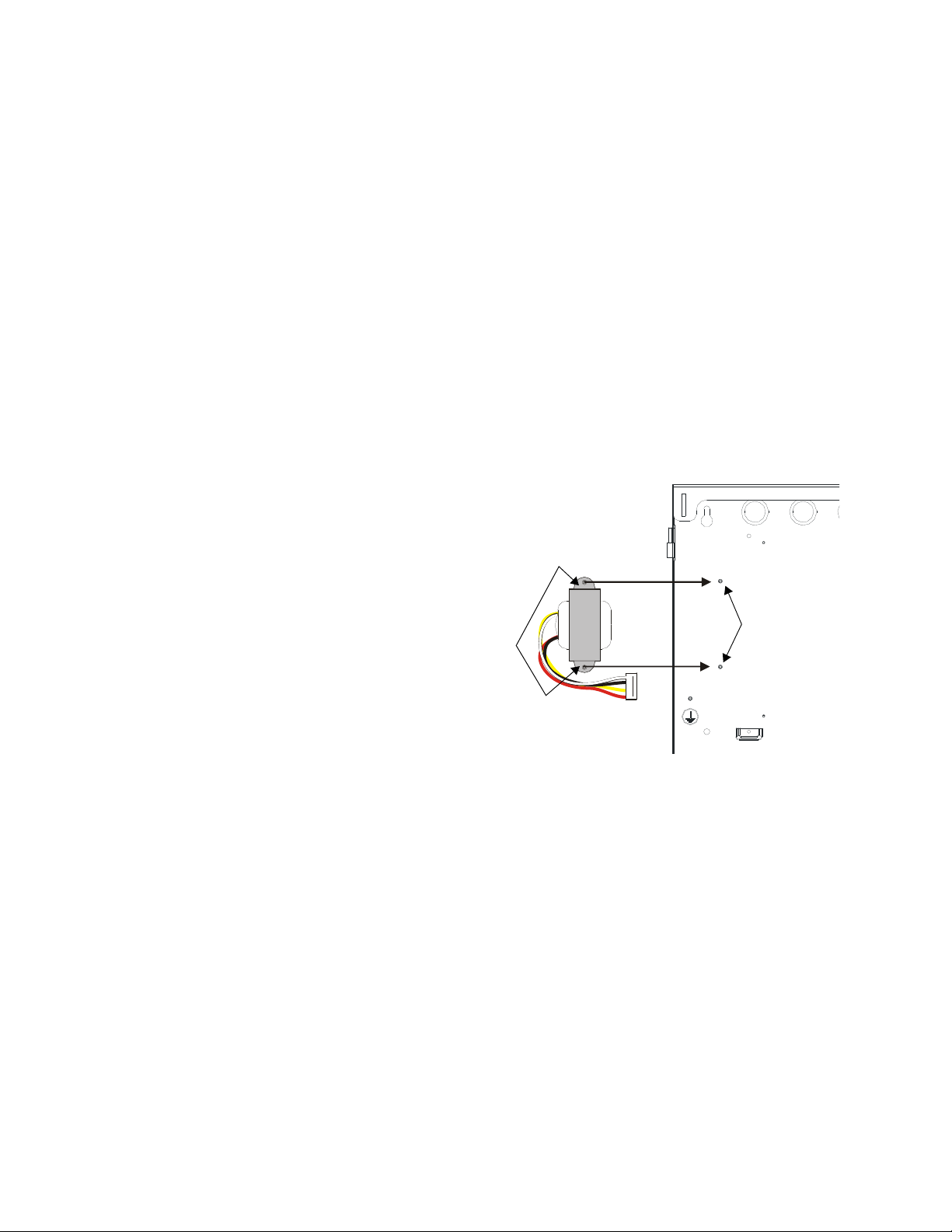
Section 2: Installation
CAUTION!
Transformer
flanges
Transformer
mounting studs
411xfmrmn2t.wmf
Ground Stud
Figure 2.1 Transformer Mounting
2.1 Mounting Options
The cabinet may be either semi-flush or surface mounted. The door is removable during the installation period by opening and lifting it off the hinges. The cabinet mounts using two key slots and
two additional 0.25" diameter holes located in the backbox. The keyslots are located at the top of
the backbox and the two securing holes at the bottom.
Carefully unpack the system and check for shipping damage. Mount the cabinet in a clean, dry,
vibration-free area where extreme temperatures are not encountered. The area should be readily
accessible with sufficient room to easily install and maintain the panel. Locate the top of the cabinet approximately five feet above the floor with the hinge mounting on the left. Determine the
number of conductors required for the devices to be installed. Sufficient knockouts are provided
for wiring convenience. Select the appropriate knockout(s) and pull the required conductors into
the box. All wiring should be in accordance with the National and/or Local codes for fire alarm
systems.
2.2 Mounting
Backbox Mounting
1. Mark and predrill holes for the top two
keyhole mounting bolts using the
dimensions shown in Figure 2.1.
2. Install two upper fasteners in the wall
with the screw heads protruding.
3. Using the upper 'keyholes', temporarily
mount the backbox over the two screws.
4. Mark the lower two holes, remove the
backbox from the wall and drill the
lower two holes in the wall.
5. Before mounting the backbox to the
wall, install the supplied transformer in
the backbox. Position the holes in the
transformer flanges over the transformer mounting studs. Refer to
Figure 2.1.
6. Secure the transformer with the supplied nuts and attached washers.
18 411UDAC Manual — P/N 51073:E 9/20/2013
Page 19
Mounting Installation
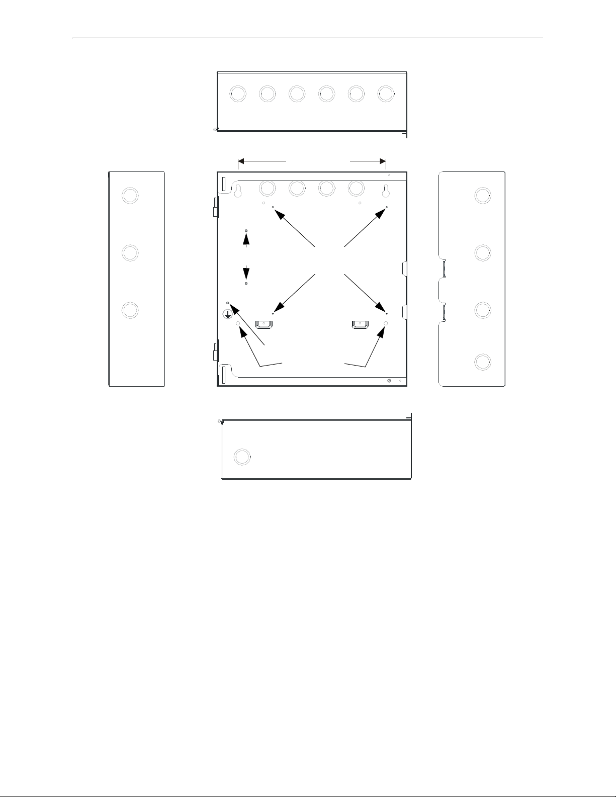
Figure 2.1 Cabinet Dimensions and Knockout Locations
411udaccab.wmf
Ground Stud
Top
Right side
Mounting Keyholes
10.0” (25.4cm)
Main Circuit Board
Mounting Studs
Transformer
Mounting Studs
Left side
Mounting Holes
Bottom
7. Mount the backbox to the keyhole mounting bolts, install and tighten the remaining fastener.
Main Circuit Board Mounting
1. When the location is clean and free of construction dust or other contaminants, install the main
PC board by installing the four supplied standoffs on the four main circuit board mounting
studs located in the backbox. Refer to Figure 2.1 for locations.
2. Position the main circuit board’s four corner mounting holes over the four standoffs just
installed. Be certain to observe the proper ESD (Electro Static Discharge) precautions to
prevent damage to the static sensitive circuits. This includes, but is not limited to, use of a
wrist strap.
3. Secure the main circuit board to the standoffs with the four supplied screws and attached
washers.
4. Plug the transformer connector into the main circuit board connector J4. The connector is
keyed and can only be plugged-in one way. Refer to Figure 2.3 on page 21 and Figure 2.11 on
page 29 for transformer connector location and AC power connections.
411UDAC Manual — P/N 51073:E 9/20/2013 19
Page 20
Installation Operating Power
!
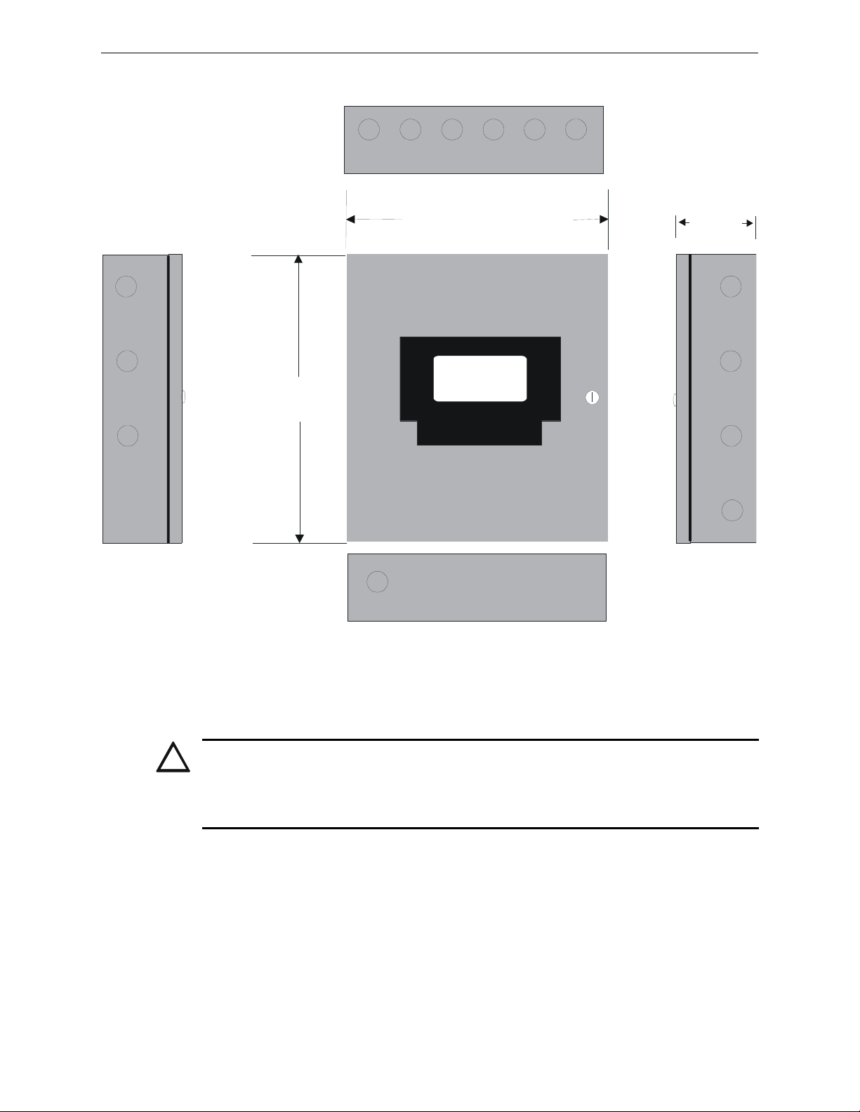
Figure 2.2 411UDAC Backbox
411accab2.wmf
Top
Door = 13.047” (33.14cm)
Backbox = 12.875” (32.7cm)
Door = 14.760” (37.49cm)
Backbox = 14.5” (36.83cm)
Depth=4.533”
(11.51cm)
Bottom
Right Side
Left Side
5. When wiring is completed, re-install the door.
2.3 Operating Power
CAUTION: DISCONNECT POWER BEFORE SERVICING
SEVERAL DIFFERENT SOURCES OF POWER CAN BE CONNECTED TO THE 411UDAC.
DISCONNECT ALL SOURCES OF POWER BEFORE SERVICING THIS UNIT. THE
COMMUNICATOR AND ASSOCIATED EQUIPMENT MAY BE DAMAGED BY REMOVING
AND/OR INSERTING MODULES OR CABLES WITH POWER APPLIED.
Primary Power Source (AC) and Earth Ground Connections
AC power connections are made inside the 411UDAC cabinet. The primary power source is 120
VAC, 60 Hz, 0.7 amps. Run a pair of wires (with ground conductor) from the protected premises
main breaker box to TB3 of the main circuit board. As per the National Electric Code, use 14
AWG (2.00 mm
nected to this circuit. In addition, this circuit must be provided with overcurrent protection and
may not contain any power disconnect devices.
2
) or heavier gauge wire with 600V insulation. No other equipment may be con-
20 411UDAC Manual — P/N 51073:E 9/20/2013
Page 21
Operating Power Installation
CAUTION!
HIGH VOLTAGE
CAUTION!
GND FAULT
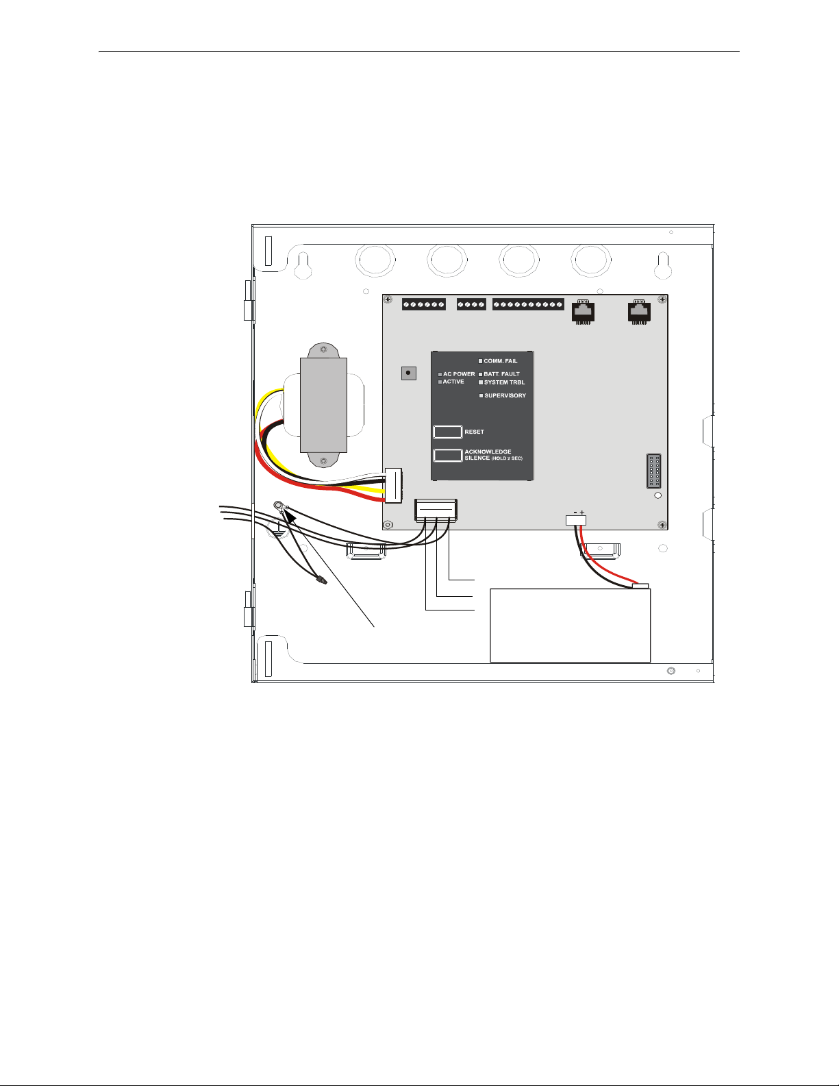
Figure 2.3 Operating Power Connections
Connect Earth Ground
Wire to earth ground stud
Earth
Red
Black
12 VDC Battery
Neutral
Hot
411udacinbox.wmf
A separate earth ground connection must be made to ensure proper panel operation and lightning
and transient protection. Remove the two keps nuts from the grounding stud in the backbox. Connect the incoming earth ground wire to supplied cable #71073 with a wire nut. Position the ring terminal end over the grounding stud. Secure with one of the keps nuts. Place the ring terminal from
the other supplied ground cable #71073 over the ground stud and secure with the second keps nut.
Wire the ground cable to the bottom position of TB3. Refer to the figure below for location of the
stud. Apply AC power to the panel only after the system is completely installed and visually
checked. Note that AC power must be applied to the panel before installing the battery interconnect
cable.
Secondary Power Source (batteries)
Observe polarity while connecting the battery. When installing one 12 volt battery for up to 12
Amp Hour applications, connect the supplied battery cable (P/N 75516) by sliding the connector
attached to the long red wire onto the positive (+) battery terminal and the connector attached to the
long black wire onto the negative (-) battery terminal. Tie-wrap or tape the two unused short wires
to the long wires.
When installing two 12 volt, 7 Amp Hour batteries (in parallel) for up to 14 Amp Hour applications, follow the same procedure as described for one battery except connect the unused short wires
to the second battery. Slide the connector attached to the short red wire onto the positive (+) terminal of the second battery and the connector attached to the short black wire onto the negative (-)
battery terminal of the second battery.
411UDAC Manual — P/N 51073:E 9/20/2013 21
Page 22
Installation Input Channels
!
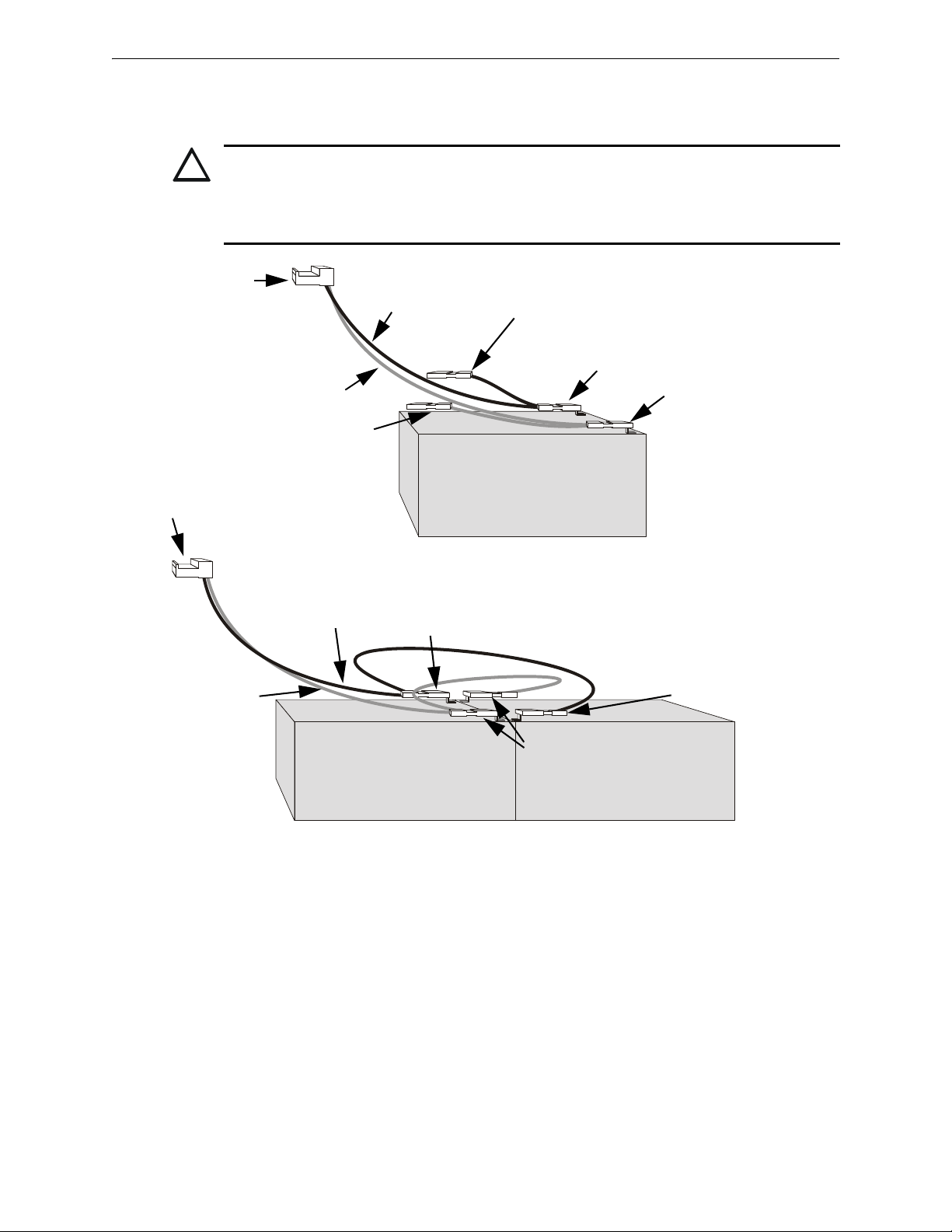
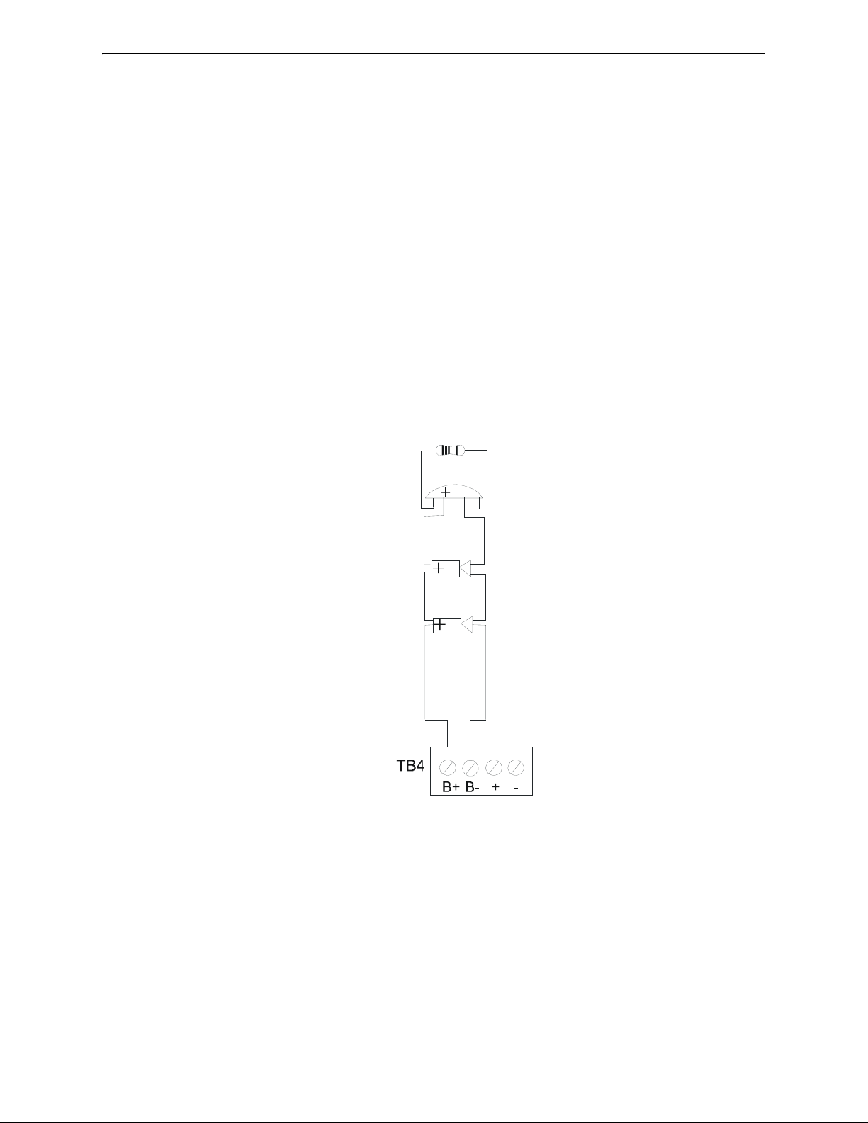
Figure 2.4 Battery Cable Connections
Two 12 Volt Batteries - Up to 14 Amp Hour Applications
One 12 Volt Battery - Up to 12 Amp Hour Applications
Black Wire
Red Wire
Negative (-) Terminal
Positive (+) Terminal
Unused wire - tie-wrap
or tape to long wires
Unused wire - tie-wrap
or tape to long wires
Connect to J3 on
411UDAC main circuit
board
Connect to J3 on 411UDAC
main circuit board
Black Wire
Red Wire
Negative (-)
Terminal
Negative (-)
Terminal
Positive (+)
Terminals
411batt2.wmf
411batt.wmf
When the panel is ready to have power applied, connect the battery cable plug to connector J3 on
the 411UDAC main circuit board. The battery charger is capable of recharging sealed lead acid
type batteries. Refer to the battery calculations table to determine the correct battery rating.
CAUTION: BATTERY CONTAINS SULFURIC ACID
THE BATTERY CONTAINS SULFURIC ACID WHICH CAN CAUSE SEVERE BURNS TO THE
SKIN AND EYES, AND CAN DESTROY FABRICS. IF CONTACT IS MADE WITH SULFURIC
ACID, IMMEDIATELY FLUSH THE SKIN OR EYES WITH WATER FOR 15 MINUTES AND SEEK
IMMEDIATE MEDICAL ATTENTION.
2.4 Input Channels
The 411UDAC has four channel inputs. Channel/input field wiring is supervised for opens (trouble), shorts (alarm) and ground faults (zero ohms impedance between panel and earth ground) by
the 411UDAC. All conditions are visually and audibly annunciated and, if programmed, communicated to a Central Station.
Each channel is a Style B (Class B) Initiating Device Circuit with the exception of channel/input 3
which can be configured for Style B or Style D (Class A). All inputs can be connected to normallyopen contact type devices. In addition, inputs 1 and 3 can be connected to conventional 4-wire
smoke detectors. Figure 2.5, “Wiring Initiating Device Circuits” on page 23 for information on
wiring Style B and Style D circuits.
22 411UDAC Manual — P/N 51073:E 9/20/2013
Page 23
Input Channels Installation
UL-listed
power
supervision
relay*
Manual Pull
Stations
(Class A)
Manual Pull
Stations
(Class B)
Waterflow
Devices
(Class B)
411UDAC Main Circuit Board
Zone 1/Channel 1
Zone 2/Channel 2
Zone 3/Channel 3
Zone 4/Channel 4
Figure 2.5 Wiring Initiating Device Circuits
411udain3.wmf
4-Wire
Smoke
Detector
*Refer to the Device Compatibility
Document for a list of compatible
relays.
Class B Initiating Device Circuits
(supervised and power-limited)
4.7 K, ½ watt resistor P/N:71252
The channel/inputs may be programmed as shown below:
• 4-wire smoke detector (inputs 1 & 3 only) • Supervisory
• Pull station • Supervisory autoresettable
• Normally-open contact device • Waterflow silenceable
• Host panel trouble • Waterflow nonsilenceable
A maximum of five waterflow devices may be used on any circuit programmed as a waterflow zone
per NFPA 72.
It is allowable to mix an assortment of device types (i.e. smoke detectors, heat detectors, pull stations, etc.) on any zone. This is not recommended, however, since specific and detailed reports will
not be possible (particularly critical when using Contact ID format). For example, the report of
general fire alarm versus pull station fire alarm or smoke detector fire alarm could not be distinguished.
The factory default programming for each channel is as follows:
Channel 1 - fire alarm (4-wire smoke)
Channel 2 - pull station
Channel 3 - fire alarm (4-wire smoke)
Channel 4 - pull station
The following illustration shows Channel 1 connected to 4-wire smoke detectors, and UL-listed
power supervision relay; Channel 2 connected to manual pull stations; Channel 3 connected to
manual pull stations; and Channel 4 connected to waterflow devices. In this example, the factory
default programming for Channel 4 must be changed from pull station to waterflow device.
411UDAC Manual — P/N 51073:E 9/20/2013 23
Page 24
Installation Input Channels
CAUTION!
HIGH VOLTAGE
COMM. FAIL
BATT FAULT
SYSTEM
TROUBLE
SUPV.
AC PWR
ACTIVE
GND FAULT
B+ A+ B- A- A B
Slc Slc Slc Slc Shield
NO NC C NO NC C NC NO C
411UDAC
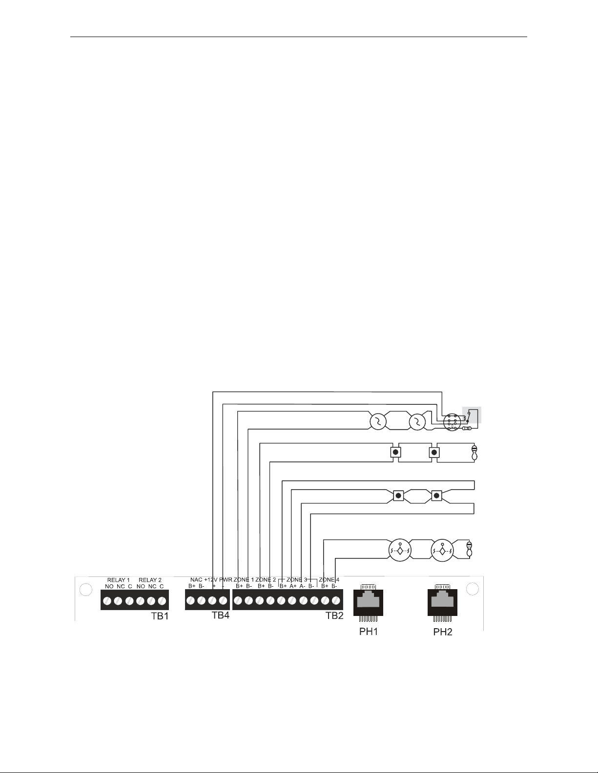
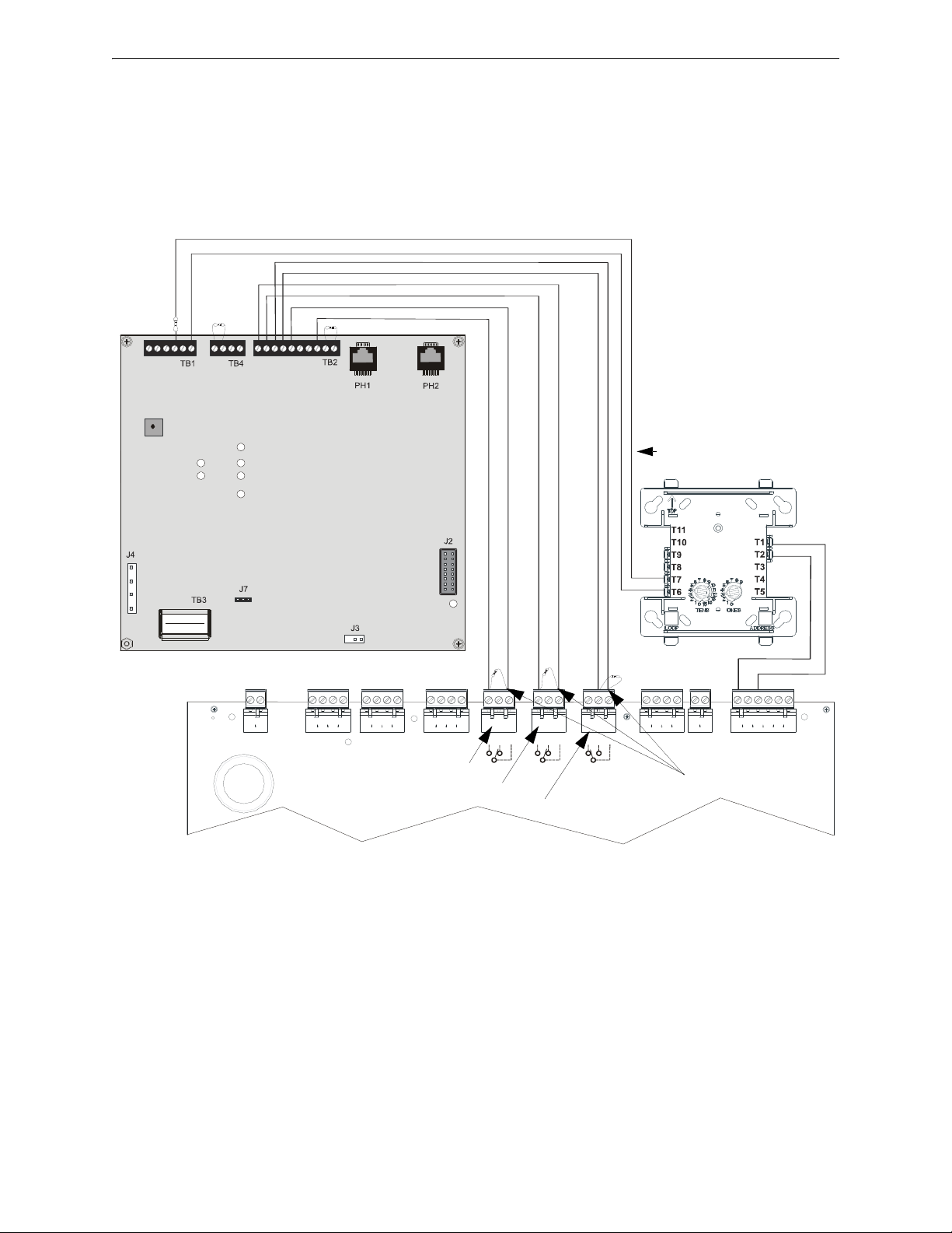
Note: The addressable monitor module input, which is
being used to monitor the 411UDAC Relay Output
programmed for DACT Trouble must be programmed as
'DACT Trouble' at the FACP. The 411UDAC must be
programmed as a Slave Communicator (programming
address 64 set to ‘2’)
Addressable FACP (must be UL-listed for Central Station Service and Remote Signaling Service)
411UDAC Relay 2 Output (DACT Trouble)
Channel 2/Zone 2
Channel 1/Zone 1
Channel 3/Zone 3
2.2K ELR Channel 4
2.2K
ELR
Monitor Circuit Input
SLC Loop
Trouble Relay
Alarm Relay
Supervisory Relay
UL listed
2.2K ELRs
P/N 27070
Program the 411UDAC as follows:
Channel 1 - Normally Open Contact Device (alarm)
Channel 2 - Host Panel Trouble
Channel 3 - Supervisory
9200udlsc411a.wmf
Monitor
Module*
ELR
supplied
with
Monitor
Module
*If the SLC device does not
match the one in this figure,
refer to the SLC manual
wiring conversion charts for
legacy and newer versions of
the modules.
Figure 2.6 Typical Addressable FACP Connection to 411UDAC
24 411UDAC Manual — P/N 51073:E 9/20/2013
Page 25
Output Circuits Installation
Figure 2.7 Notification Appliance Circuit Connections
Style Y (Class B) Notification Appliance Circuit
(supervised and power-limited).
2.2K ohms, ½ watt P/N 27070
Polarized Bell
Polarized Horn
Polarized Horn
Dummy Load NAC circuit with 2.2K ohm,
½ watt End-of-Line resistor if not being used.
Note: Notification Appliance Circuit
polarity shown in alarm state
411anac.wmf
NAC +12V Power
2.5 Output Circuits
Notification Appliance Circuit
The 411UDAC provides one Style Y (Class B) NAC (Notification Appliance Circuit). The NAC is
supervised and power-limited and is capable of 1.0 amp of current. Refer to the Device Compati-
bility Document for a listing of compatible notification appliances.
Notes:
1. The 411UDAC can only be used to supplement host panel NACs.
2. Do not connect strobes to the 411UDAC Notification Appliance Circuit.
The NAC may be programmed as follows:
• Silenceable
• Nonsilenceable (waterflow)
• Silence Inhibited (one minute)
• Autosilence (5 to 30 minutes)
411UDAC Manual — P/N 51073:E 9/20/2013 25
Page 26
Installation Output Circuits
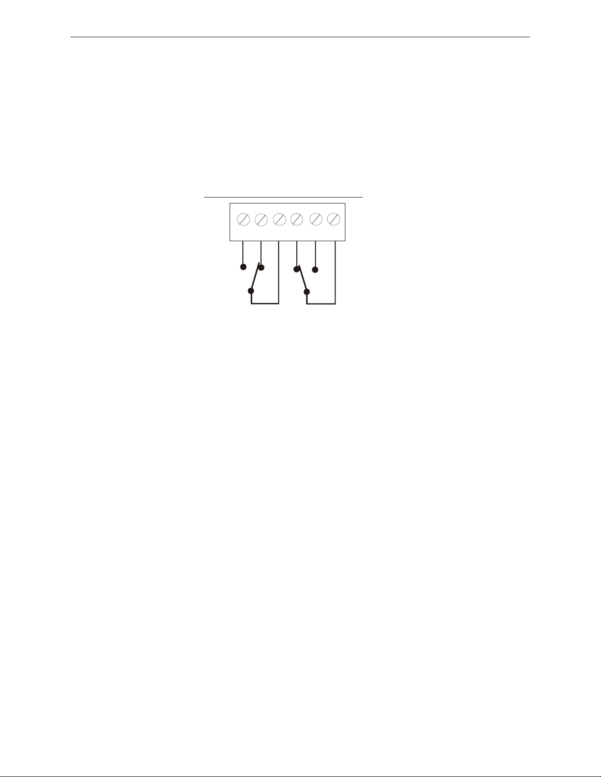
RELAY 1 RELAY 2
TB1
NO NONC NCCC
Figure 2.8 Programmable Relay
Note: Relay connections may be power-limited or nonpower-limited. However, connecting one type next to the
other type is not allowed. Both circuits must be either power-limited or nonpower-limited.
Relays automatically change to energized
condition when programmed for Trouble.
411arele.wmf
Relay 1 - Shown Programmed for Alarm,
Supervisory, or any other function except
DACT Trouble and Host Panel Trouble
(relay contacts shown in de-energized
condition with power applied to 411UDAC)
Relay 2 - Shown Programmed for
DACT Trouble or Host Panel
Trouble (relay contacts shown in
energized condition with power
applied to 411UDAC)
Relay Programming
The relays are programmable for activation on fire alarm, host panel trouble, fire supervisory, total
communication failure and DACT. Refer to “DACT Programming” on page 36. Addresses ‘85 88’ are used for programming relay functions and enable.
26 411UDAC Manual — P/N 51073:E 9/20/2013
Page 27

Telephone Circuits Installation
!
To Premises Phone
Green Wire
Red Wire
Red Wire
Tip
Ring
Ring
Tip
Ring
Tip
Ring
Tip
To Premises Phone
(Primary Lines) Incoming
Telco Phone Lines
(Secondary Lines) Incoming
Telco Phone Lines
Note: Shorting bars
inside RJ31X Jack
removed during male
plug insertion
7 foot Cable (MCBL-
7) Not supplied -
Order Separately
(2 required)
Secondary Phone Line PH2
Male Plug
Connectors
Primary Phone Line PH1
411UDAC
Green Wire
Female
Connectors
411ajak2.wmf
Figure 2.9 Wiring Phone Jacks
2.6 Telephone Circuits
Provision to connect two independent telephone lines is available via two telephone jacks labeled
PH1 (Primary) and PH2 (Secondary). Telephone line control/command is possible via double line
seizure as well as usage of an RJ31X style interconnection. (RJ31X jacks must be ordered separately).
CAUTION: PROPER FUNCTIONALITY
IT IS CRITICAL THAT THE 411UDAC BE LOCATED AS THE FIRST DEVICE ON THE INCOMING
TELEPHONE CIRCUIT TO PROPERLY FUNCTION.
411UDAC Manual — P/N 51073:E 9/20/2013 27
Page 28
Installation Optional Programmer
CAUTION!
HIGH VOLTAGE
COMM. FAIL
BATT FAULT
SYSTEM
TROUBLE
SUPV.
AC PWR
ALARM
GND FAULT
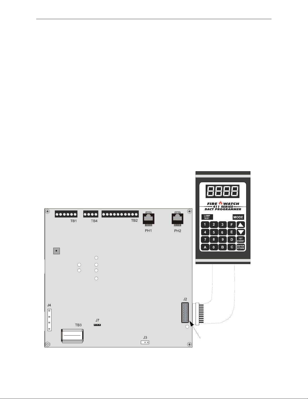
Figure 2.10 Programmer Connection to 411UDAC
Cable attached
to Programmer
411UDAC
Programmer
J2 connector
411a-pro2.wmf
- +
NOTE: The Fire•Watch 411 Series DACT
Programmer must be removed when not in use.
2.7 Optional Programmer
The Fire-Watch 411 Series DACT Programmer (Model PRO-411) is used to:
switch between the digital alarm communicator's five Modes of operation
set the digital alarm communicator's 24 hour internal clock in Real-Time Clock Mode
program the 411UDAC digital alarm communicator in Program Mode
test the status of input and output circuits (including telephone lines) in Troubleshoot Mode
return all digital alarm communicator programming to the factory default settings in Default
Mode
To use the PRO-411 Programmer:
1. Remove all power from the 411UDAC.
2. Unlock and open the 411UDAC door.
3. Connect the Programmer cable to connector J2 located in the lower right corner of the
411UDAC. Note that the key on the connector must align with the slot in the J2 connector.
4. Reapply power to the 411UDAC.
5. Operate the Programmer by pressing the MODE key. Enter the appropriate four digit code
and then press the [ENTER/STORE] key.
Note that it is not possible to switch from Normal Mode to any other mode if any of the four Channels is programmed for fire alarm or fire supervisory and is active, that is, in alarm (shorted).
28 411UDAC Manual — P/N 51073:E 9/20/2013
Page 29

UL Power-limited Wiring Requirements Installation
CAUTION!
HIGH VOLTAGE
CAUTION!
GND FAULT
Figure 2.11 Typical UL Power-limited Wiring Diagram
AC Power
Nonpower-limited
Nonpower-limited Circuits
Power-limited Circuits
411aulpw2.wmf
Note: Relay connections may be power-limited or nonpowerlimited, provided that 0.25" spacing is maintained between
conductors of power-limited and nonpower-limited circuits.
Nonpower-limited Circuits
2.8 UL Power-limited Wiring Requirements
Power-limited and nonpower-limited circuit wiring must remain separated in the cabinet. All
power-limited circuit wiring must remain at least 0.25” away from any nonpower-limited circuit
wiring. Furthermore, all power-limited and nonpower-limited circuit wiring must enter and exit the
cabinet through different knockouts and/or conduits. A typical wiring diagram for the 411UDAC is
shown below.
411UDAC Manual — P/N 51073:E 9/20/2013 29
Page 30

Section 3: Modes of Operation
The 411UDAC has five operational modes:
• Normal Mode
• Real Time Clock Mode
• Program Mode (requires password)
• Troubleshoot Mode
• Default Mode (requires password)
The operational mode for the 411UDAC is Normal Mode. The operator is able to switch between
any modes of operation provided no alarm events are active in the system. It should be noted that
the unit will not respond to input activations while in any mode except Normal Mode.
Some modes require a password. Refer to Section 3.2.
Access to any other Mode requires connection of the PRO-411 DACT Programmer which consists
of a keypad and display. Figure 3.1, “Programmer Keypad” on page 31.
Note that if the 411UDAC is configured to operate as a Slave Communicator, it will attempt to
transmit all panel status to a Central Station. If set to operate in the Test Communicator configuration, the 411UDAC will function as a local slave panel only without transmitting panel status to a
Central Station.
3.1 Normal Mode
Normal Mode is the standard (default) mode of operation for the 411UDAC. The unit continuously
monitors the status of the four input channels as well as the status of the onboard digital communicator. If no activity is detected on the four input channels (no shorts or opens) and the 411UDAC is
operating free of internal troubles, the unit will display the following conditions:
All LEDs are off except the AC Power LED
NAC output is off
Onboard piezo sounder is off
The relays are in their normal deactivated state
Communicator is not transmitting to the Central Station
The 411UDAC transmits system status reports to a central station, if programmed to do so, via the
public switched telephone network. Two supervised telephone line connections are made to interface the digital communicator to the telephone lines. Both telephone lines are supervised by the
411UDAC for proper voltage.
The 411UDAC is capable of line seizure on both the primary and secondary telephone line interfaces. Any time the digital communicator detects the necessity to call the Central Station, line sei-
zure will disconnect any local premises phones sharing the same telephone line. Sharing of phone
lines, for fire systems, must be approved by the Local Authority Having Jurisdiction. All transmis-
sions to the Central Station will be sent over the Primary phone line. In the event of a noisy or
faulty phone line, transmissions will be sent over the backup Secondary phone line.
Transmission options exist to:
• send reports to the secondary phone number as backup only
• send reports to both the primary and secondary phone numbers
• send reports to the first available central station phone number
If 10 total attempts to communicate are unsuccessful, the 411UDAC will turn on the Communication Fail LED.
30 411UDAC Manual — P/N 51073:E 9/20/2013
Page 31

Normal Mode Modes of Operation
Figure 3.1 Programmer Keypad
Select operating mode
Increment memory address
Decrement memory address
One press = first memory address
Two presses = type any address
Save data, go to next address
Address entry keys are 0 to 9.
Data entry keys are 0 to 9 and A to F.
pr411key.wmf
The 411UDAC meets NFPA 72 requirements for Remote Station Protective Signaling Service and
Central Station Signaling Service reporting requirements for: (a) the type of signal, (b) condition
and (c) location of the reporting premises. See “Central Station Communications” on page 54, for
additional information.
The 411UDAC can be switched from Normal Mode to any other Mode, provided no channel programmed for fire alarm or fire supervisory is active, that is, in alarm (shorted). The PRO-411
DACT Programmer, for use with the Fire•Watch 411 Series, must be connected to the 411UDAC in
order to change from mode to mode.
3.1.1 Programmer Key Functions
MODE KEY
Pressing the MODE key followed by a valid 4-digit numerical code and the [ENTER/STORE]
key selects one of the five modes of operation. To enter Normal Mode from any other mode, press
the MODE key followed by 6676 and then [ENTER/STORE].
If an incorrect key is entered, reenter the proper 4-digit code before
[ENTER/STORE] key. Note that as information is entered into the 411UDAC, the digits will
scroll across the Programmer display from right to left.
A pause of up to 10 seconds between each number is allowed while entering the code.
LAMP TEST KEY
Pressing the Lamp Test key on the Programmer, while the digital communicator is in Normal
Mode, will cause the front panel LEDs and all segments of the four 7-segment display on the
411UDAC to light. A Lamp Test can only be performed in Normal Mode. The Lamp Test key can
also be used in Troubleshoot Mode to view the 12 volt resettable power value.
– 6676 spells NORM on a Touch-Tone
___6
__66
_667
6676
®
phone.
pressing the
411UDAC Manual — P/N 51073:E 9/20/2013 31
Page 32

Modes of Operation Password Creation and Entry
00_F
(address)
(data)
0.
Digit to be programmed
8_.
Digit to be programmed
86_.
1st EVENT KEY
This key, along with the UP and DOWN arrow keys, are used only in Program Mode. Press the 1st
EVENT key at any time to display the first program memory address and its content. The follow-
ing may be displayed on the Programmer:
If the 1st EVENT key is pressed a second time, the following will be displayed on the Programmer
display:
The contents of any address can be viewed by entering the digits of the desired address. For example, to view the contents of address 86, press the '8' key on the keypad. '8' will appear as the first
digit in the display, a blank will appear in the position of the second digit and the decimal point will
move one position to the right, indicating that the next digit can now be entered.
Press the '6' key on the keypad. '6' will appear as the second digit on the display and the decimal
point will move one position to the right. Press the [ENTER/STORE] to view the contents of
address 86.
DOWN ARROW
Use the DOWN arrow key to decrement the memory address and view its content.
UP ARROW
Use the UP arrow key to increment the memory address and view its content.
ENTER/STORE
Stores entry into nonvolatile E2 memory located on the 411UDAC printed circuit board, then increments to the next higher address.
3.1.2 Programmer Display
Four 7-segment red LED characters provide visual display of information in the various modes of
operation.
3.2 Password Creation and Entry
In order to access the Default Mode or Programming Mode, a valid password must be entered.
1. Press the MODE key followed by the 4-digit entry code (3337 for Default Mode or 7764 for
Program Mode).
2. Press the [ENTER/STORE] key. The display will read LinP indicating that a valid password
is required to continue.
32 411UDAC Manual — P/N 51073:E 9/20/2013
Page 33

Real Time Clock Mode Modes of Operation
0.001
Digit to be programmed
10.01
Digit to be programmed
3. For the initial power-up of the 411UDAC or for the first power-up after a manually defaulted
password, key in the default password 0000 and press [ENTER/STORE]. The display will
then read dC_P.
4. Press d to continue with the default password or press C to change to a new password.
5. If d is entered in step 4, the display goes directly to the programming/default modes.
6. If C is entered in step 4, the display will read En_P prompting for a new password.
• Key in a new 4-digit password. Valid passwords are any four digit code from 0001-9999.
• The display will then read rEnP. Key in the new password again for verification.
• Once the new password has been verified, the programming/default modes will be accessed.
If at any time a password was entered incorrectly, the display will read AErr indicating an invalid
entry was made.
3.3 Real Time Clock Mode
Real Time Clock Mode is entered by pressing the MODE key followed by the 4-digit entry code
2525 and pressing the [ENTER/STORE] key. Accessing this mode requires authentication. Refer
to Section 3.2.
– 2525 spells CLCK on a Touch-Tone
®
phone.
If an incorrect key is entered, reenter the proper 4-digit code before
pressing the
[ENTER/STORE] key. Note that as information is entered into the 411UDAC, the digits will
scroll across the Programmer display from right to left.
___2
__25
_252
2525
A pause of up to 10 seconds between each number is allowed while entering the code. After pressing the [ENTER/STORE] key, the 411UDAC will be in Real Time Clock Mode. A maximum of
10 minutes idle time is allowed at this point before beginning program entries and between each
key stroke, otherwise, the 411UDAC will return to Normal Mode. Note that the time is not stored
until the fourth and final digit is selected and the [ENTER/STORE] key is pressed. If the
411UDAC returns to Normal Mode prior to entering the fourth digit, no changes will be stored and
the original time is retained.
On entering Real Time Clock Mode, 0.001 will appear on the Programmer display:
The time is displayed in military time. Note the position of the decimal point in the display. This
indicates that the first digit to be programmed is the one to the left of the decimal point. To program the first hour digit, press the corresponding number on the Programmer keypad and then press
the [ENTER/STORE] key. For example, to program 2:00 PM (1400 in military time), press '1' on
the keypad and then the [ENTER/STORE] key. The number '1' will appear as the far left digit and
the decimal point will move one position to the right indicating that the second digit from the left is
now ready for programming.
411UDAC Manual — P/N 51073:E 9/20/2013 33
Page 34

Modes of Operation Program Mode
140.1
Digit to be programmed
1400.
Digit to be programmed
Enter the second hour digit (4 in this example) and press the [ENTER/STORE] key. The number
'4' will appear as the digit second from the left and the decimal point will move one position to the
right indicating that the third digit from the left is now ready for programming.
Enter the first minute digit (0 in this example) and press the [ENTER/STORE] key. The number
'0' will appear as the digit third from the left and the decimal point will move one position to the
right indicating that the fourth digit from the left is now ready for programming.
Enter the second minute digit (0 in this example) and press the [ENTER/STORE] key. The number '0' will appear as the digit fourth from the left. Following the entry of the fourth and final digit,
the operating mode will immediately switch to Normal Mode, indicating that programming of the
time is now completed.
To exit Real Time Clock Mode before completing clock programming, press the MODE key, followed by the 4-digit code for an alternate mode and then the [ENTER/STORE] key. During Real
Time Clock Mode, if no key is pressed within 10 minutes, the 411UDAC will revert to Normal
Mode.
Note that upon power-up, the internal clock starts running at 00:01 midnight. It must be changed so
that the 411UDAC can accurately call in test signals to the Central Station. Upon power loss or on
entering Default Mode, the clock reverts to 00:01 midnight and must be reset.
3.4 Program Mode
NOTICE TO USERS, INSTALLERS, AUTHORITIES HAVING JURISDICTION
AND OTHER INVOLVED PARTIES
This product incorporates field-programmable software. In order for the product to comply with the requirements in the Standard
for Control Units and Accessories for Fire Alarm Systems, UL 864, certain programming features or options must be limited to
specific values or not used at all as indicated below:
Program feature
or option
AC Loss Delay Y
Input Channel 1-4
Delay Timer
Trouble Call Limit N
Permitted in
UL 864? (Y/N)
Possible settings
AC Loss Delay = 0, 1, 2 (factory default), 6, 7, 8, 10, 11, 12, 13, 14,
15, 16, 17, or 18 hours
Refer to “AC Loss Reporting Delay (60)” on page 45.
Y 0 – 179 seconds
Refer to “Input Channel 1 Delay Timer (69 - 71)” on page 46
Program Address 96 = 0 (factory default): unlimited calling to
Central Station for any trouble condition
Program Address 96 = 1: limits call for each unique trouble to 10
within a 24 hour period
Refer to “Trouble Call Limit - Dialer Runaway Prevention (96)” on
page 50
Settings permitted in
UL 864
AC Loss Delay =
1 or 2 hours
Delay timer =
0 - 90 seconds
Program Address
96 = 0 for unlimited
Central Station
trouble calls
All programming selections made during Program Mode are stored in nonvolatile memory. This
ensures that the 411UDAC will retain all entries made in Programming Mode even if power is
removed.
34 411UDAC Manual — P/N 51073:E 9/20/2013
Page 35

Program Mode Modes of Operation
00_F
(address)
(data)
The user must program the primary and secondary phone numbers, account numbers, 24-hour test
report times and verify event codes for each Central Station account. The 411UDAC is shipped
with the program options/features already factory programmed. Alternative options/features may
be programmed if desired. If all factory default settings are acceptable, programming is complete.
Program Mode is entered by pressing the MODE key followed by the 4-digit program mode entry
code 7764 and pressing the [ENTER/STORE] key. Accessing this mode requires authentication.
Refer to Section 3.2.
– 7764 spells PROG on a Touch-Tone
®
phone.
If an incorrect key is entered, reenter the proper 4-digit code before
pressing the
[ENTER/STORE] key. Note that as information is entered into the 411UDAC, the digits will
scroll across the Programmer display from right to left.
___7
__77
_776
7764
A pause of up to 10 seconds between each number is allowed while entering the code. After pressing the [ENTER/STORE] key, the 411UDAC will be in Program Mode. A maximum of 10 minutes idle time is allowed at this point before beginning program entries and between each key
stroke, otherwise, the unit will return to Normal Mode. All entries made prior to the 10 minute
time-out are valid and are stored.
Once in Program Mode, the 411UDAC will:
Light the DACT Trouble LED
Activate Relay if programmed for DACT trouble
Ignore all other keys other than those mentioned in this section
Display 00_F on the Programmer display
Continue to communicate any events not previously acknowledged at a central station prior
to entering Programming Mode
Communicate an 'Off Normal' event to the Central Station
Turn off piezo
While in Program Mode, the first three locations on the left of the Programmer display represent
the memory address and the last location (farthest right) represents the contents of the memory
address. The first address displayed is shown below:
Certain program items will be locked from editing if the communicator is active (dialing, transmitting, etc.). These programming locations are ‘00-19’ Primary Central Station Phone Number, ‘20’
Primary Central Station Communications Format, ‘21-24’ Primary Central Station Account Code,
‘30-49’ Secondary Central Station Phone Number, ‘50’ Secondary Central Station Communications Format, ‘51-54’ Secondary Central Station Account Code, ‘61’ Central Station Backup
Reporting and ‘145-end’ Event Codes.
To unlock these locations, either wait until the communicator stops transmitting or disable the communicator via address location 64 by changing the content of this address to ‘0.’
When desired changes have been completed, exit Programming Mode by pressing the MODE key,
followed by the 4-digit code for an alternate mode and then the [ENTER/STORE] key. During
Program Mode, if no key is pressed within 10 minutes, the unit will revert to Normal Mode.
411UDAC Manual — P/N 51073:E 9/20/2013 35
Page 36

Modes of Operation Program Mode
4 8 4 7 1 6 1 F F F F F F F F F F F F F
00 01 02 03 04 05 06 07 08 09 10 11 12 13 14 15 16 17 18 19
Entry
Address
The Programmer cable should not be removed from the 411UDAC unless the unit is in Normal
Mode. If the Programmer cable is removed while the 411UDAC is in a Mode other than Normal
Mode, the communicator will automatically revert to Normal Mode following a 10 minute
time-out
period. Note that if the Programmer is in Troubleshoot Mode when the cable is removed, the
411UDAC will revert to Normal Mode following a 20 minute
time-out period.
3.4.1 DACT Programming
Primary Central Station Phone Number (00 - 19)
The first twenty add8resses (00 - 19) are factory set to 'F' (00_F to 19_F). Programming is done as
follows:
If your phone number is 484-7161, press 4.
The display will read 00_4.
Press [ENTER/STORE] to save the entry to memory and increment to the next address
01_F.
Enter the remaining numbers in their respective addresses as shown below:
Valid entries for both the primary and secondary phone numbers are 0 to 9 and A to F with the
numeric digits as dialed numbers and the hexadecimal digits representing the following functions:
• A = * on a Touch-Tone phone keypad
• B = # on a Touch-Tone phone keypad
• C = look for secondary dial tone for up to two seconds (then dial anyway)
• D = three second pause
• E = five second pause
• F = end of phone number (Note: F must remain in all unused phone number addresses)
If the first digit of the Primary Central Station Phone Number remains ‘F’ and the digital communicator is enabled for transmission to a Central Station, a primary phone number fault will be generated. The phone number must begin with a digit other than ‘F.’
New FCC regulations allow extra digits to the CIC (Carrier ID Code), to identify the long distance
carrier. The expanded phone number field of 20 digits facilitates this function. Simply enter the
digits required by the telephone company if desired.
Primary Central Station Number Communication Format (20)
One location is needed to select the Communication Format to the primary phone number. Address
20 is used for this purpose. The factory default setting for this address is 'E', which is Contact ID
Format. You may enter '0' through 'D' in place of the default, then press [ENTER/STORE].
Choose from the list of formats below:
0: 4+1 Ademco Express Standard, DTMF, 1400/2300 ACK
1: 4+2 Ademco Express Standard, DTMF, 1400/2300 ACK
2: 3+1 Standard 1800 Hz Carrier, 2300 Hz ACK
3: 3+1 Expanded 1800 Hz Carrier, 2300 Hz ACK
4: 3+1 Standard 1900 Hz Carrier, 1400 Hz ACK
5: 3+1 Expanded 1900 Hz Carrier, 1400 Hz ACK
6: 4+1 Standard 1800 Hz Carrier, 2300 Hz ACK
7: 4+1 Expanded 1800 Hz Carrier, 2300 Hz ACK
8: 4+1 Standard 1900 Hz Carrier, 1400 Hz ACK
36 411UDAC Manual — P/N 51073:E 9/20/2013
Page 37

Program Mode Modes of Operation
1451
(address)
(data)
9: 4+1 Expanded 1900 Hz Carrier, 1400 Hz ACK
A: 4+2 Standard 1800 Hz Carrier, 2300 Hz ACK
B: 4+2 Expanded 1800 Hz Carrier, 2300 Hz ACK
C: 4+2 Standard 1900 Hz Carrier, 1400 Hz ACK
D: 4+2 Expanded 1900 Hz Carrier, 1400 Hz ACK
E: Contact ID, DTMF, 1400/2300 ACK
F: Future use
Consult the Central Station for proper Format selection. For any Format chosen, all event codes
are automatically programmed by the 411UDAC. Refer to Table 3.1, “Ademco Contact ID Format
- Primary,” on page 37, Table 3.2, “4+2 Standard and 4+2 Express Formats - Primary,” on
page 38 and Table 3.3, “All 3+1, 4+1 and 4+2 Expanded Formats - Primary,” on page 39.
Event Codes - Setting Entries
The Format selected in address 20 will cause the 411UDAC to automatically program addresses
145 - 228 with the factory default settings. Any of the Event Code settings may be altered. Consult
your Central Station prior to altering the event code settings. An entry of all zeros for any event
code will cause the communicator to NOT
both Central Station phone numbers may be disabled.
Upon accessing the first event code address (address 145) shown in Table 3.2, the following may be
displayed on the Programmer 7-Segment Display, if the corresponding Format was selected in
address 20.
transmit the report. Transmission of reports to either or
The first three locations on the left of the Programmer display represent the memory address 145 of
the Format previously selected in address 20. The last location 1 (farthest right) represents the contents of memory address 145 (which is the first digit of the event code).
The following Tables list the data which is automatically programmed for each Format that can be
selected in address 20. The addresses shown in each Table contain the Setting data which is automatically programmed by the 411UDAC. To change the value, key in the new digit and then press
the [ENTER/STORE] key to save the new value. Use the Up and Down Arrow keys to increment
to the next address or decrement to the previous address.
Ademco Contact ID Format Primary Central Station Event Codes
If 'E' is entered for address 20, the following data is automatically programmed for the Primary
Central Station phone number event codes. Enter '000' for the Setting to disable the report to the
Central Station. The Channel # is not programmable.
Address Description Setting Channel/Input #
145 - 147 Primary # Input Channel 1 Active Event Code 111 001
148 - 150 Primary # Input Channel 2 Active Event Code 115 002
151 - 153 Primary # Input Channel 3 Active Event Code 111 003
154 - 156 Primary # Input Channel 4 Active Event Code 115 004
157 - 159 Primary # Input Channel 1 Fault Event Code 380 001
160 - 162 Primary # Input Channel 2 Fault Event Code 380 002
163 - 165 Primary # Input Channel 3 Fault Event Code 380 003
166 - 168 Primary # Input Channel 4 Fault Event Code 380 004
169 - 171 Primary # AC Voltage Fault Event Code 301 000
172 - 174 Primary # Earth Fault Event Code 310 000
Table 3.1 Ademco Contact ID Format - Primary
411UDAC Manual — P/N 51073:E 9/20/2013 37
Page 38

Modes of Operation Program Mode
Address
175 -177 Primary # Low Battery Fault Event Code 302 000
178 - 180 Primary # No Battery Fault Event Code 311 000
181 - 183 Primary # Phone Line 1 Voltage Fault Event Code 351 000
184 - 186 Primary # Phone Line 2 Voltage Fault Event Code 352 000
187 - 189 Primary # NAC Fault Event Code 321 000
190 - 192 Primary # Charger Fault Event Code 300 000
193 - 195 Primary # Phone Number 1 Communication Fault Event Code 354 001
196 - 198 Primary # Phone Number 2 Communication Fault Event Code 354 002
199 - 201 Primary # System Off Normal Fault Event Code 308 000
202 - 204 Primary # System Test Message 602 000
205 - 207 Primary # System Abnormal Test Message 608 000
208 - 210 Primary # Upload/Download Request Code 411 000
211 - 213 Primary # Upload Successful Code 416 000
214 - 216 Primary # Download Successful Code 412 000
217 - 219 Primary # Upload/Download Failed Code 413 000
Description Setting Channel/Input #
Table 3.1 Ademco Contact ID Format - Primary
4+2 Standard and 4+2 Express Formats Primary Central Station Event Codes
If ‘1, A or C’ is entered for address 20, the following data is automatically programmed for the Primary Central Station phone number event codes. Enter '00' for the Setting to disable the report to
the Central Station.
Address Description Setting
145 - 146 Primary # Input Channel 1 Active Event Code 11
147 - 148 Primary # Input Channel 2 Active Event Code 12
149 - 150 Primary # Input Channel 3 Active Event Code 13
151 - 152 Primary # Input Channel 4 Active Event Code 14
153 - 154 Primary # Input Channel 1 Fault Event Code F1
155 - 156 Primary # Input Channel 2 Fault Event Code F2
157 - 158 Primary # Input Channel 3 Fault Event Code F3
159 - 160 Primary # Input Channel 4 Fault Event Code F4
161 - 162 Primary # AC Fault Event Code 92
163 - 164 Primary # Earth Fault Event Code 61
165 - 166 Primary # Low Battery Fault Event Code 62
167 - 168 Primary # No Battery Fault Event Code 63
169 - 170 Primary # Phone Line 1 Voltage Fault Event Code 64
171 - 172 Primary # Phone Line 2 Voltage Fault Event Code 65
173 - 174 Primary # NAC Fault Event Code 66
175 - 176 Primary # Charger Fault Event Code 47
177 - 178 Primary # Phone Number 1 Communication Fault Event Code 6A
179 - 180 Primary # Phone Number 2 Communication Fault Event Code 6B
181 - 182 Primary # System Off Normal Fault Event Code 6F
183 - 184 Primary # Input Channel 1 Active Restore Code E1
185 - 186 Primary # Input Channel 2 Active Restore Code E2
187 - 188 Primary # Input Channel 3 Active Restore Code E3
189 - 190 Primary # Input Channel 4 Active Restore Code E4
191 - 192 Primary # Input Channel 1 Fault Restore Code D1
193 - 194 Primary # Input Channel 2 Fault Restore Code D2
195 - 196 Primary # Input Channel 3 Fault Restore Code D3
Table 3.2 4+2 Standard and 4+2 Express Formats - Primary
38 411UDAC Manual — P/N 51073:E 9/20/2013
Page 39

Program Mode Modes of Operation
Address
197 - 198 Primary # Input Channel 4 Fault Restore Code D4
199 - 200 Primary # AC Voltage Fault Restore Code 93
201 - 202 Primary # Earth Fault Restore Code A1
203 - 204 Primary # Low Battery Fault Restore Code A2
205 - 206 Primary # No Battery Fault Restore Code A3
207 - 208 Primary # Phone Line 1 Voltage Fault Restore Code A4
209 - 210 Primary # Phone Line 2 Voltage Fault Restore Code A5
211 - 212 Primary # NAC Fault Restore Code A6
213 - 214 Primary # Charger Fault Restore Code 57
215 - 216 Primary # Phone Number 1 Communication Fault Restore Code AA
217 - 218 Primary # Phone Number 2 Communication Fault Restore Code AB
219 - 220 Primary # System Off Normal Restore Code AF
221 - 222 Primary # System Test Message 99
223 - 224 Primary # System Abnormal Test Message 91
225 - 226 Primary # Upload/Download Request Code 71
227 - 228 Primary # Upload Successful Code 72
229 - 230 Primary # Download Successful Code 73
231 - 232 Primary # Upload/Download Failed Code 74
Description Setting
Table 3.2 4+2 Standard and 4+2 Express Formats - Primary
All 3+1, 4+1 and 4+2 Expanded Formats Primary Central Station Event Codes
If ‘0, 2, 3, 4, 5, 6, 7, 8, 9, B or D’ is entered for address 20, the following data is automatically programmed for the Primary Central Station phone number event codes. Enter '0' for the Setting to
disable the report to the Central Station.
Address Description Setting
145 Primary # Input Channel 1 Active Event Code 1
146 Primary # Input Channel 2 Active Event Code 1
147 Primary # Input Channel 3 Active Event Code 1
148 Primary # Input Channel 4 Active Event Code 1
149 Primary # Input Channel 1 Fault Event Code F
150 Primary # Input Channel 2 Fault Event Code F
151 Primary # Input Channel 3 Fault Event Code F
152 Primary # Input Channel 4 Fault Event Code F
153 Primary # AC Power Fault Event Code 9
154 Primary # Earth Fault Event Code 6
155 Primary # Low Battery Fault Event Code 6
156 Primary # No Battery Fault Event Code 6
157 Primary # Phone Line 1 Voltage Fault Event Code 6
158 Primary # Phone Line 2 Voltage Fault Event Code 6
159 Primary # NAC Fault Event Code 6
160 Primary # Charger Fault Event Code 4
161 Primary # Phone Number 1 Communication Fault Event Code 6
162 Primary # Phone Number 2 Communication Fault Event Code 6
163 Primary # System Off Normal Fault Code 6
164 Primary # Input Channel 1 Active Restore Code E
165 Primary # Input Channel 2 Active Restore Code E
166 Primary # Input Channel 3 Active Restore Code E
167 Primary # Input Channel 4 Active Restore Code E
168 Primary # Input Channel 1 Fault Restore Code D
169 Primary # Input Channel 2 Fault Restore Code D
170 Primary # Input Channel 3 Fault Restore Code D
Table 3.3 All 3+1, 4+1 and 4+2 Expanded Formats - Primary
411UDAC Manual — P/N 51073:E 9/20/2013 39
Page 40

Modes of Operation Program Mode
Address Description Setting
171 Primary # Input Channel 4 Fault Restore Code D
172 Primary # AC Voltage Fault Restore Code 9
173 Primary # Earth Fault Restore Code A
174 Primary # Low Battery Fault Restore Code A
175 Primary # No Battery Fault Restore Code A
176 Primary # Phone Line 1 Voltage Fault Restore Code A
177 Primary # Phone Line 2 Voltage Fault Restore Code A
178 Primary # NAC Fault Restore Code A
179 Primary # Charger Fault Restore Code
180 Primary # Phone Number 1 Communication Fault Restore Code A
181 Primary # Phone Number 2 Communication Fault Restore Code A
182 Primary # System Off Normal Restore Code A
183 Primary # System Test Message 9
184 Primary # System Abnormal Test Message F
185 Primary # Upload/Download Request Code 7
186 Primary # Upload Successful Code 7
187 Primary # Download Successful Code 7
188 Primary # Upload/Download Failed Code 7
*
Table 3.3 All 3+1, 4+1 and 4+2 Expanded Formats - Primary
* For Formats ‘B’ and ‘D’, this address is defaulted to ‘9’ instead of ‘F.’
Primary Central Station Number Account Code (21 - 24)
The four locations at addresses 21 - 24 default to all '0's. Valid entries are 0 - 9 and A - F. The number of digits entered must match the format selection. If programming '2, 3, 4 or 5' into address 20,
enter three digits (one digit each in locations 21, 22 and 23 - location 24 is ignored). If programming '0, 1, 6, 7, 8, 9, A, B, C, D or E' into address 20, enter four digits (one each in locations 21, 22,
23 and 24).
Primary Central Station Number 24 Hour Test Time (25 - 28)
Use military time when entering the 24 hour 'test' time. The 24 hour test report to phone number 1
takes up four locations, from addresses 25 - 28. The default is 00:00 (12:00 midnight). The limits
for each location are as follows (do not use values of A - F as entries).
25: enter 0, 1 or 2
26: enter 0 - 9
27: enter 0 - 5
28: enter 0 - 9
Primary Central Station Number 24/12/8/6 Hour Test Time Interval (29)
The test report sent to the Primary phone number may be sent every 6, 8, 12 or 24 hours. If the
message is to be sent every 24 hours, leave the factory default entry of '0'. If other test report times
are needed, enter 1 = 12 hour, 2 = 8 hour or 3 = 6 hour.
Secondary Central Station Phone Number (30 - 49)
Addresses 30 - 49 are factory set to 'F' (30_F to 49_F). Programming is typically done as follows:
If your phone number is 484-7161, press 4.
The display will read 30_4.
Press [ENTER/STORE] to save the entry to memory and increment to the next address
31_F.
40 411UDAC Manual — P/N 51073:E 9/20/2013
Page 41

Program Mode Modes of Operation
4 8 4 7 1 6 1 F F F F F F F F F F F F F
30 31 32 33 34 35 36 37 38 39 40 41 42 43 44 45 46 47 48 49
Entry
Address
Enter the remaining numbers in their respective addresses as shown below:
Valid entries for both the primary and secondary phone numbers are 0 to 9 and A to F with the
numeric digits as dialed numbers and the hexadecimal digits representing the following functions:
• A = * on a Touch-Tone phone keypad
• B = # on a Touch-Tone phone keypad
• C = look for secondary dial tone for up to two seconds (then dial anyway)
• D = three second pause
• E = five second pause
• F = end of phone number (Note: F must remain in all unused phone number addresses)
If the first digit of the Secondary Central Station Phone Number remains ‘F’ and the digital communicator is enabled for transmission to a Central Station, a secondary phone number fault will be
generated. The phone number must begin with a digit other than ‘F.’
Secondary Central Station Number Communication Format (50)
One location is needed to select the Communication Format to the secondary phone number.
Address 50 is used for this purpose. The factory default setting for this address is 'E', which is Contact ID Format. You may enter '0' through 'D' in place of the default, then press [ENTER/STORE].
Choose from the list of formats below:
0: 4+1 Ademco Express Standard, DTMF, 1400/2300 ACK
1: 4+2 Ademco Express Standard, DTMF, 1400/2300 ACK
2: 3+1 Standard 1800 Hz Carrier, 2300 Hz ACK
3: 3+1 Expanded 1800 Hz Carrier, 2300 Hz ACK
4: 3+1 Standard 1900 Hz Carrier, 1400 Hz ACK
5: 3+1 Expanded 1900 Hz Carrier, 1400 Hz ACK
6: 4+1 Standard 1800 Hz Carrier, 2300 Hz ACK
7: 4+1 Expanded 1800 Hz Carrier, 2300 Hz ACK
8: 4+1 Standard 1900 Hz Carrier, 1400 Hz ACK
9: 4+1 Expanded 1900 Hz Carrier, 1400 Hz ACK
A: 4+2 Standard 1800 Hz Carrier, 2300 Hz ACK
B: 4+2 Expanded 1800 Hz Carrier, 2300 Hz ACK
C: 4+2 Standard 1900 Hz Carrier, 1400 Hz ACK
D: 4+2 Expanded 1900 Hz Carrier, 1400 Hz ACK
E: Contact ID, DTMF, 1400/2300 ACK
F: Future use
The Format selected in address 50 will cause the 411UDAC to automatically program addresses
229 - 312 with the factory default settings. Any of the Event Code settings may be altered. Consult
your Central Station prior to altering the event code settings. An entry of all zeros for any event
code will cause the communicator to NOT
transmit the report. Transmission of reports to either or
both Central Station phone numbers may be disabled.
Refer to “Central Station Communications” on page 54 for information on Format reporting.
411UDAC Manual — P/N 51073:E 9/20/2013 41
Page 42

Modes of Operation Program Mode
2291
(address)
(data)
Upon accessing the first event code address which is 229 (Table 3.5, “4+2 Standard and 4+2
Express Formats - Secondary,” on page 43), the following may be displayed on the Programmer’s
7-Segment Display, if the corresponding Format was selected in address 50.
The first three locations on the left of the Programmer’s display represent the memory address 229.
The last location 1 (farthest right) represents the contents of memory address 229 which is the first
digit of the event code.
The following Tables list the data which is automatically programmed for each Format that can be
selected in address 50. The addresses shown in each Table contain the event code Setting data
which is automatically programmed by the 411UDAC. To change the value, key in the new digits
and then press the [ENTER/STORE] key to save the new value. Use the Up and Down Arrow
keys to increment to the next address or decrement to the previous address.
Ademco Contact ID Format Secondary Central Station Event Codes
If ‘E’ is entered for address 50, the following data is automatically programmed for the Secondary
Central Station phone number event codes. Enter '000' for the Setting to disable the report to the
Central Station.
Address Description Setting Channel/Input #
233 - 235 Secondary # Input Channel 1 Active Event Code 111 001
236 - 238 Secondary # Input Channel 2 Active Event Code 115 002
239 - 241 Secondary # Input Channel 3 Active Event Code 111 003
242 - 244 Secondary # Input Channel 4 Active Event Code 115 004
245 - 247 Secondary # Input Channel 1 Fault Event Code 380 001
248 - 250 Secondary # Input Channel 2 Fault Event Code 380 002
251 - 253 Secondary # Input Channel 3 Fault Event Code 380 003
254 - 256 Secondary # Input Channel 4 Fault Event Code 380 004
257 - 259 Secondary # AC Voltage Fault Event Code 301 000
260 - 262 Secondary # Earth Fault Event Code 310 000
263 - 265 Secondary # Low Battery Fault Event Code 302 000
266 - 268 Secondary # No Battery Fault Event Code 311 000
269 - 271 Secondary # Phone Line 1 Voltage Fault Event Code 351 000
272 - 274 Secondary # Phone Line 2 Voltage Fault Event Code 352 000
275 - 277 Secondary # NAC Fault Event Code 321 000
278 - 280 Secondary # Charger Fault Event Code 300 000
281 - 283 Secondary # Phone Number 1 Communication Fault Event Code 354 001
284 - 286 Secondary # Phone Number 2 Communication Fault Event Code 354 002
287 - 289 Secondary # System Off Normal Fault Event Code 308 000
290 - 292 Secondary # System Test Message 602 000
293 - 295 Secondary # System Abnormal Test Message 608 000
296 - 298 Secondary # Upload/Download Request Code 411 000
299 - 301 Secondary # Upload Successful Code 416 000
302 - 304 Secondary # Download Successful Code 412 000
305 - 307 Secondary # Upload/Download Failed Code 413 000
Table 3.4 Ademco Contact ID Format - Secondary
42 411UDAC Manual — P/N 51073:E 9/20/2013
Page 43

Program Mode Modes of Operation
4+2 Standard and 4+2 Express Formats Secondary Central Station Event Codes
If 1, A or C is entered for address 50, the following data is automatically programmed for the Secondary Central Station phone number event codes. Enter '00' for the Setting to disable the report to
the Central Station.
Address Description Setting
233 - 234 Secondary # Input Channel 1 Active Event Code 11
235 - 236 Secondary # Input Channel 2 Active Event Code 12
237 - 238 Secondary # Input Channel 3 Active Event Code 13
239 - 240 Secondary # Input Channel 4 Active Event Code 14
241 - 242 Secondary # Input Channel 1 Fault Event Code F1
243 - 244 Secondary # Input Channel 2 Fault Event Code F2
245 - 246 Secondary # Input Channel 3 Fault Event Code F3
247 - 248 Secondary # Input Channel 4 Fault Event Code F4
249 - 250 Secondary # AC Fault Event Code 92
251 - 252 Secondary # Earth Fault Event Code 61
253 - 254 Secondary # Low Battery Fault Event Code 62
255 - 256 Secondary # No Battery Fault Event Code 63
257 - 258 Secondary # Phone Line 1 Voltage Fault Event Code 64
259 - 260 Secondary # Phone Line 2 Voltage Fault Event Code 65
261 - 262 Secondary # NAC Fault Event Code 66
263 - 264 Secondary # Charger Fault Event Code 47
265 - 266 Secondary # Phone Number 1 Communication Fault Event Code 6A
267 - 268 Secondary # Phone Number 2 Communication Fault Event Code 6B
269 - 270 Secondary # System Off Normal Fault Event Code 6F
271 - 272 Secondary # Input Channel 1 Active Restore Code E1
273 - 274 Secondary # Input Channel 2 Active Restore Code E2
275 - 276 Secondary # Input Channel 3 Active Restore Code E3
277 - 278 Secondary # Input Channel 4 Active Restore Code E4
279 - 280 Secondary # Input Channel 1 Fault Restore Code D1
281 - 282 Secondary # Input Channel 2 Fault Restore Code D2
283 - 284 Secondary # Input Channel 3 Fault Restore Code D3
285 - 286 Secondary # Input Channel 4 Fault Restore Code D4
287 - 288 Secondary # AC Voltage Fault Restore Code 93
289 - 290 Secondary # Earth Fault Restore Code A1
291 - 292 Secondary # Low Battery Fault Restore Code A2
293 - 294 Secondary # No Battery Fault Restore Code A3
295 - 296 Secondary # Phone Line 1 Voltage Fault Restore Code A4
297 - 298 Secondary # Phone Line 2 Voltage Fault Restore Code A5
299 - 300 Secondary # NAC Fault Restore Code A6
301 - 302 Secondary # Charger Fault Restore Code 57
303 - 304 Secondary # Phone Number 1 Communication Fault Restore Code AA
305 - 306 Secondary # Phone Number 2 Communication Fault Restore Code AB
307 - 308 Secondary # System Off Normal Restore Code AF
309 - 310 Secondary # System Test Message 99
311 - 312 Secondary # System Abnormal Test Message 91
313 - 314 Secondary # Upload/Download Request Code 71
315 - 316 Secondary # Upload Successful Code 72
317 - 318 Secondary # Download Successful Code 73
319 - 320 Secondary # Upload/Download Failed Code 74
Table 3.5 4+2 Standard and 4+2 Express Formats - Secondary
411UDAC Manual — P/N 51073:E 9/20/2013 43
Page 44

Modes of Operation Program Mode
All 3+1, 4+1 and 4+2 Expanded Formats Secondary Central Station Event Codes
If 0, 2, 3, 4, 5, 6, 7, 8, 9, B or D is entered for address 50, the following data is automatically programmed for the Secondary Central Station phone number event codes. Enter '0' for the Setting to
disable the report to the Central Station.
Address Description Setting
233 Secondary # Input Channel 1 Active Event Code 1
234 Secondary # Input Channel 2 Active Event Code 1
235 Secondary # Input Channel 3 Active Event Code 1
236 Secondary # Input Channel 4 Active Event Code 1
237 Secondary # Input Channel 1 Fault Event Code F
238 Secondary # Input Channel 2 Fault Event Code F
239 Secondary # Input Channel 3 Fault Event Code F
240 Secondary # Input Channel 4 Fault Event Code F
241 Secondary # AC Power Fault Event Code 9
242 Secondary # Earth Fault Event Code 6
243 Secondary # Low Battery Fault Event Code 6
244 Secondary # No Battery Fault Event Code 6
245 Secondary # Phone Line 1 Voltage Fault Event Code 6
246 Secondary # Phone Line 2 Voltage Fault Event Code 6
247 Secondary # NAC Fault Event Code 6
248 Secondary # Charger Fault Event Code 4
249 Secondary # Phone Number 1 Communication Fault Event Code 6
250 Secondary # Phone Number 2 Communication Fault Event Code 6
251 Secondary # System Off Normal Fault Code 6
252 Secondary # Input Channel 1 Active Restore Code E
253 Secondary # Input Channel 2 Active Restore Code E
254 Secondary # Input Channel 3 Active Restore Code E
255 Secondary # Input Channel 4 Active Restore Code E
256 Secondary # Input Channel 1 Fault Restore Code D
257 Secondary # Input Channel 2 Fault Restore Code D
258 Secondary # Input Channel 3 Fault Restore Code D
259 Secondary # Input Channel 4 Fault Restore Code D
260 Secondary # AC Voltage Fault Restore Code 9
261 Secondary # Earth Fault Restore Code A
262 Secondary # Low Battery Fault Restore Code A
263 Secondary # No Battery Fault Restore Code A
264 Secondary # Phone Line 1 Voltage Fault Restore Code A
265 Secondary # Phone Line 2 Voltage Fault Restore Code A
266 Secondary # NAC Fault Restore Code A
267 Secondary # Charger Fault Restore Code 5
268 Secondary # Phone Number 1 Communication Fault Restore Code A
269 Secondary # Phone Number 2 Communication Fault Restore Code A
270 Secondary # System Off Normal Restore Code A
271 Secondary # System Test Message 9
272 Secondary # System Abnormal Test Message F
273 Secondary # Upload/Download Request Code 7
274 Secondary # Upload Successful Code 7
275 Secondary # Download Successful Code 7
276 Secondary # Upload/Download Failed Code 7
Table 3.6 All 3+1, 4+1 and 4+2 Expanded Formats - Secondary
* For Formats ‘B’ and ‘D’, this address is defaulted to ‘9’ instead of ‘F.’
*
44 411UDAC Manual — P/N 51073:E 9/20/2013
Page 45

Program Mode Modes of Operation
Secondary Central Station Number Account Code (51 - 54)
The four locations at addresses 51 - 54 default to all '0's. Valid entries are 0 - 9 and A - F. The number of digits entered must match the format selection. If programming '2, 3, 4 or 5' into address 50,
enter three digits (one digit each in locations 51, 52 and 53 - location 54 is ignored). If programming '0, 1, 6, 7, 8, 9, A, B, C, D or E' into address 50, enter four digits (one each in locations 51, 52,
53 and 54).
Secondary Central Station Number 24 Hour Test Time (55 - 58)
Use military time when entering the 24 hour 'test' time. The 24 hour test report to phone number 1
takes up four locations, from addresses 55 - 58. The default is 00:00 (12:00 midnight). The limits
for each location are as follows (do not use values of A - F as entries):
55: enter 0, 1 or 2
56: enter 0 - 9
57: enter 0 - 5
58: enter 0 - 9
Secondary Central Station Number 24/12/8/6 Hour Test Time Interval (59)
The test report sent to the Secondary phone number may be sent every 6, 8, 12 or 24 hours. If the
message is to be sent every 24 hours, leave the factory default entry of '0'. If other test report times
are needed, enter 1 = 12 hour, 2 = 8 hour or 3 = 6 hour.
AC Loss Reporting Delay (60)
Enter a digit of 0 - 9 or A - F corresponding to the number of hours to be delayed in reporting the
loss of AC power. The factory default is '2' for 2 hours. The valid entries are '0' = no delay; '1' = 1
hours; '2' = 2 hours; '3' = 6 hours; '4' = 7 hours; '5' = 8 hours; '6' = 9 hours; '7' = 10 hours; '8' = 11
hours; '9' = 12 hours; 'A' = 13 hours; 'B' = 14 hours; 'C' = 15 hours; 'D' = 16 hours; 'E' = 17 hours;
'F' = 18 hours.
UL requires a 1-3 hour delay.
Backup Reporting (61)
Leaving address 61 at '0' means that reports will be transmitted to the secondary Central Station
phone number only if attempts to communicate to the primary Central Station phone number are
unsuccessful. Programming a '1' causes all reports to be transmitted to both the primary and secondary Central Station phone numbers. Programming a '2' causes reports to go to the first available
receiver.
Do not alter this entry while the digital communicator is active!
Reserved for Future Use (62)
DACT Trouble Reminder (63)
The factory default entry of '0' in address location 63 disables the trouble reminder feature. Selecting '1' for location 63 will cause a reminding beep (after the Silence switch is pressed) every 15 seconds for active alarms and every two minutes during a DACT trouble condition. The beeps from
the onboard piezo sounder will occur until the alarm or DACT fault is cleared. The piezo sounder
will begin beeping at a rate of one second On and one second Off after 24 hours unless the DACT
fault has been cleared.
Operational Mode Selection (64)
The factory default setting is ‘0’ for latching inputs and the onboard communicator disabled. This
prevents the unit from transmitting status information to the Central Station(s).
411UDAC Manual — P/N 51073:E 9/20/2013 45
Page 46

Modes of Operation Program Mode
Address 64 Setting 411UDAC Operational Mode 411UDAC Function
0 Stand-alone/Communicator Disabled latching inputs/onboard communicator disabled
1 Stand-alone/Communicator Enabled latching inputs/onboard communicator enabled
2 Slave/Communicator Enabled non-latching inputs/onboard communicator enabled
3 Slave/Communicator Disabled non-latching inputs/onboard communicator disabled
Table 3.7 411UDAC Operational Modes
Input Channel 1 Function Selection (65)
1
Factory default for Channel 1 is '0' for activation on fire alarm (4-wire smoke). Enter '1' for pull
station; '2' for normally open contact device; '3' for host panel trouble; '4' for fire supervisory; '5' for
fire supervisory autoresettable; '6' for waterflow silenceable; '7' for waterflow nonsilenceable.
Input Channel 2 Function Selection (66)
1
Factory default for Channel 2 is '1' for pull station. Enter '2' for normally open contact device; '3'
for host panel trouble; '4' for fire supervisory; '5' for fire supervisory autoresettable; '6' for waterflow silenceable; '7' for waterflow nonsilenceable.
Note that '0' is not a valid entry.
Input Channel 3 Function Selection (67)
1
Factory default for Channel 3 is '0' for activation on fire alarm (4-wire smoke). Enter '1' for pull
station; '2' for normally open contact device; '3' for host panel trouble; '4' for fire supervisory; '5' for
fire supervisory autoresettable; '6' for waterflow silenceable; '7' for waterflow nonsilenceable.
Input Channel 4 Function Selection (68)
1
Factory default for Channel 4 is '1' for pull station. Enter '2' for normally open contact device; '3'
for host panel trouble; '4' for fire supervisory; '5' for fire supervisory autoresettable; '6' for waterflow silenceable; '7' for waterflow nonsilenceable.
Note that '0' is not a valid entry.
Input Channel 1 Delay Timer (69 - 71)
2
The Delay Timer is used to delay digital communicator transmission to a Central Station when the
Input Channel is activated. Input Channel 1 Delay Timer is factory set to '000' seconds for no
delay. The timer may be programmed for a delay of from 0 to 179 seconds. Inputs programmed for
fire alarm, pull station, host control panel trouble and fire supervisory, must not
be delayed. A
delay, therefore, cannot be selected for inputs programmed for these fire applications. If the input
is set for a waterflow function, the delay timer will also delay activation of the relay, piezo sounder
and LEDs.
Input Channel 2 Delay Timer (72 - 74)
2
The Delay Timer is used to delay digital communicator transmission to a Central Station when the
Input Channel is activated. Input Channel 2 Delay Timer is factory set to '000' seconds for no
delay. The timer may be programmed for a delay of from 0 to 179 seconds. Inputs programmed for
fire alarm, pull station, host control panel trouble and fire supervisory, must not
be delayed. A
delay, therefore, cannot be selected for inputs programmed for these fire applications. If the input
is set for a waterflow function, the delay timer will also delay activation of the relay, piezo sounder
and LEDs.
1. Changing the input function will automatically change the corresponding Primary and
Secondary event codes to reflect the new input function. The Communication Format
should be programmed first, followed by the Input Channel Function. See “Events and
Default Event Codes” on page 79.
2. This timer does not delay LED or Output Relay activation and is not used for channels
programmed as AC Loss circuits.
46 411UDAC Manual — P/N 51073:E 9/20/2013
Page 47

Program Mode Modes of Operation
Input Channel 3 Delay Timer (75 - 77)
The Delay Timer is used to delay digital communicator transmission to a Central Station when the
Input Channel is activated. Input Channel 3 Delay Timer is factory set to '000' seconds for no
delay. The timer may be programmed for a delay of from 0 to 179 seconds. Inputs programmed for
fire alarm, pull station, host control panel trouble and fire supervisory, must not
delay, therefore, cannot be selected for inputs programmed for these fire applications. If the input
is set for a waterflow function, the delay timer will also delay activation of the relay, piezo sounder
and LEDs.
Input Channel 4 Delay Timer (78 - 80)
The Delay Timer is used to delay digital communicator transmission to a Central Station when the
Input Channel is activated. Input Channel 4 Delay Timer is factory set to '000' seconds for no
delay. The timer may be programmed for a delay of from 0 to 179 seconds. Inputs programmed for
fire alarm, pull station, host control panel trouble and fire supervisory, must not
delay, therefore, cannot be selected for inputs programmed for these fire applications. If the input
is set for a waterflow function, the delay timer will also delay activation of the relay, piezo sounder
and LEDs.
1
be delayed. A
1
be delayed. A
Touchtone/Rotary Select for Primary Phone (81)
A '0' programmed in this address by the factory, triggers Touchtone dialing over the primary phone
line. Select '1' for rotary dialing.
Make/Break Ratio for Primary Phone (82)
This address is used only if a '1' has been programmed for address 81. The Make/Break ratio is factory set to '0' which is 67/33 ratio, but may be changed to '1' which is 62/38 ratio.
Touchtone/Rotary Select for Secondary Phone (83)
A '0' programmed in this address by the factory, triggers Touchtone dialing over the secondary
phone line. Select '1' for rotary dialing.
Make/Break Ratio for Secondary Phone (84)
This address is used only if a '1' has been programmed for address 83. The Make/Break ratio is factory set to '0' which is 67/33 ratio, but may be changed to '1' which is 62/38 ratio.
Output Relay #1 Enable (85)
The factory default setting for Output Relay #1 is '0' for disabled. Enter '1' to enable the relay.
Output Relay #1 Function Selections (86)
The Output Relay can be programmed to activate for any one of six conditions. The factory default
for address 86 is '0' for activation on fire alarm. Program a '1' for host panel trouble; '2' for DACT
trouble; '3' for latching fire supervisory; '4' for autoresettable fire supervisory; '8' for total communication failure.
Output Relay #2 Enable (87)
The factory default setting for Output Relay #2 is '0' for disabled. Enter '1' to enable the relay.
Output Relay #2 Function Selections (88)
Output Relay #2 can be programmed to activate for any one of six conditions. The factory default
for address 88 is '2' for activation on DACT trouble. Program a '0' for activation on fire alarm; '1'
for host panel trouble; '3' for latching fire supervisory; '4' for autoresettable fire supervisory; '8' for
total communication failure.
1. This timer does not delay LED or Output Relay activation and is not used for channels
programmed as AC Loss circuits.
411UDAC Manual — P/N 51073:E 9/20/2013 47
Page 48

Modes of Operation Program Mode
Figure 3.2 Verification Timing Diagram
Detector Zone
Goes Into Alarm
Detector Alarm
Verification
Different Detector
Zone Alarm
RESET/
RETARD
RESTART
ALARM VERIFICATION PERIOD
84 Sec.
24 Sec.
8 Sec.0 Sec.
24
60 SECOND CONFIRMATION TIME
Alarm Ignored Panel Processes Alarm if Same Detector Zone is Still in Alarm
Panel Immediately Processes Alarm
Reserved for Future Use (89)
Leave default setting of '0'
Panel Unlock (90)
The communicator must be unlocked to accept a remote upload/download. Leaving the default setting of '0' will require the unlock code 8655 be entered for each data transfer session (30 minute
timeout). Enter ‘1’ to keep the communicator in a permanent unlocked state.
Alarm Verification Enable (91)
Alarm verification works only on zones programmed as 4-wire smoke detector zones (i.e. zones 1
and 3). After detecting an alarm, the panel removes power from four-wire smoke zones, resetting
all 4-wire smoke detectors. Power is reapplied and a 16 second restart period allows detectors to
stabilize. During the retard/reset/restart period of 24 seconds, subsequent alarms by the same initiating zone are ignored. An alarm detected on any other 4-wire detector zone during the restart
period will cause immediate verified alarms. A subsequent alarm on the initiating zone occurring
within the confirmation time will cause a verified alarm.
NOTE: Mixing devices on zones designated as 4-wire smoke zones is not recommended. The
communicator will not transmit a signal to the Central Station signifying that alarm verification is in
progress.
48 411UDAC Manual — P/N 51073:E 9/20/2013
During the alarm verification period, access to other modes of operation is prevented.
Factory Default is no verification which is an entry of '0'. Entering '1' enables verification. Alarm
Verification is ignored if the 411UDAC is configured for nonlatching Slave Communicator operation or Test Mode.
NOTE: Consult local Authority Having Jurisdiction (AHJ) prior to altering this address.
Silence Inhibit Notification Appliance Circuit (92)
Setting address 92 to '1' prevents the silencing or resetting of the Notification Appliance Circuit for
one minute following an alarm. The factory default setting is '0' for no silence inhibit.
Autosilence Notification Appliance Circuit (93)
The Notification Appliance Circuit may be autosilenced after a programmed time interval between
5 and 30 minutes. Enter '1' for 5 minute autosilence; '2' for 10 minutes; '3' for 15 minutes; '4' for 20
minutes; '5' for 25 minutes; '6' for 30 minutes. The factory default is '0' for no autosilence.
Page 49

Program Mode Modes of Operation
Restoral Method (94)
Restoral Method refers to the communication of Restoral Events to a Central Station. It has no
effect on the actual input circuit restoral itself.
• Typical Restoral Method - ‘0’ entry programs the panel to transmit each input circuit restoral,
as it occurs, to the Central Station. In Slave Mode, this means that as soon as an input restores,
the communicator will immediately transmit the Restoral Event to the Central Station. In
Stand-alone Mode, the restoral of inputs programmed as Autoresettable Supervisory will also
cause the communicator to transmit a Restoral Event immediately. All other input types in
Stand-alone Mode are latching and their restoral will not communicate a Restoral Event until
the Reset Switch is pressed.
• Conditional Restoral Method #1 - ‘1’ entry programs the panel to transmit each input circuit
restoral, as it occurs, to the Central Station. In Slave Mode, this means that as soon as an input
restores, the communicator will immediately transmit the Restoral Event to the Central Station.
In Stand-alone Mode, the restoral of inputs programmed as Autoresettable Supervisory will
also cause the communicator to transmit a Restoral Event immediately. All other input types
in Stand-alone Mode are latching and the communication of their Restoral Events are
dependent upon an after-reset condition.
The input circuit must be physically clear of an input short upon completion of the reset period.
If, and only if, the input circuit is normal (clear of an input short) after the reset period will the
communicator transmit a Restoral Event to the Central Station. If the input circuit remains
active after the reset period, no transmission will take place.
• Conditional Restoral Method #2 - ‘2’ entry programs the panel to transmit each input circuit
restoral if, and only if, all input circuits are normal (clear of an input short). In Slave Mode,
this means that as soon as all input circuits are restored, the communicator will transmit the
Restoral Event(s) to the Central Station. In Stand-alone Mode, the restoral of inputs
programmed as either Autoresettable Supervisory will cause the communicator to transmit a
Restoral Event if, and only if, all input circuits are normal
alone Mode are latching and the communication of their Restoral Events are dependent upon
an after-reset condition. If, and only if, all input circuits are normal (clear of an input short)
after the reset period will the communicator transmit a Restoral Event(s) to the Central Station.
If any input circuit remains active after the reset period, no transmission will take place, even if
other input circuits are truly restored.
1
. All other input types in Stand-
1. Latching input circuits will never restore in Stand-alone Mode until the Reset Switch is
pressed. If both an Autoresettable input circuit and a Latching input circuit are activated
and subsequently cleared, only the Autoresettable input circuit will restore, but no
transmission will occur to the Central Station since there is still an input circuit active (the
Latching input circuit).
411UDAC Manual — P/N 51073:E 9/20/2013 49
Page 50

Modes of Operation Program Mode
Table 3.8 describes the events that would take place after the reset period, according to each unique
Communicator Restoral Method. It is assumed that an input circuit is active before reset.
Input Circuit After
Reset
SHORTED
NOT SHORTED
Typical Restoral Method
All local annunciation of the active
event stops. The short is
rediscovered after reset period
and local annunciation begins
*
again.
The panel communicates:
1. A Restoral Event
2. An Active Event
All local annunciation of the active
event stops. The circuit is found
to be in a normal state.
The panel communicates:
1. A Restoral Event
†
Conditional Restoral
Method #1
All local annunciation of the
active event stops. The short is
rediscovered after reset period
and local annunciation begins
*
again.
The panel communicates nothing
because this input is still in an
active state after reset.
All local annunciation of the
active event stops. The circuit is
found to be in a normal state.
The panel communicates:
1. A Restoral Event
Conditional Restoral
Method #2
All local annunciation of the
active event stops. The short is
rediscovered after reset period
and local annunciation begins
*
again.
The panel communicates nothing
because an input (can be any
input) is still in an active state
after reset.
All local annunciation of the
active event stops. The circuit is
found to be in a normal state.
If, and only if, all
found to be in a normal state will
the panel communicate:
1. A Restoral Event
Otherwise, the panel will
communicate nothing.
input circuits are
Table 3.8 Restoral Methods
* Local annunciation is dependent upon input circuit function. Inputs programmed as waterflow devices
will not annunciate until the waterflow retard period has expired. Inputs programmed as 4-wire smoke
devices, with the Alarm Verification feature enabled, will not annunciate until the alarm is verified.
† Inputs programmed with a delay will not communicate the Active Event until the delay period has
expired.
Coding, Notification Appliance Circuit (95)
Coding of the Notification Appliance Circuit is selectable as ‘0’ for no coding (steady) or ‘1’ for
Temporal (½ second On, ½ second Off, ½ second On, ½ second Off, ½ second On, 1½ second Off).
Factory default is ‘0’ for no coding (steady). Note that this NAC should only be used to supplement
host panel NACs.
Trouble Call Limit - Dialer Runaway Prevention (96)
Factory default setting of '0' in address 96, allows the digital communicator to call the Central Station each time any DACT trouble and any active Channel programmed for host panel trouble is
detected by the 411UDAC. Programming a '1' in this address enables the Trouble Call Limit feature, which limits the number of 411UDAC and Input Channel Trouble calls to the Central Station
to 10 calls for each unique trouble event within a 24 hour period. Separate limit counters keep
track of each unique type of trouble (e.g. open input channel). To clear the limit counters, disable
and then enable this location. Note that the number of phone line (communication) faults called to
the Central Station are not limited by this feature. No subsequent restoral message is sent to the
Central Station(s) for a particular trouble whose limit of 10 calls has been reached. Local DACT
annunciation will still track the particular trouble and restoral.
Panel Identification Number (97 - 100)
The Panel Identification Number is a 4-digit code (valid digits are 0 to F) that is used to identify the
installed panel. It is important to program this 4-digit code at the job site the first time that downloading is performed so that the called Service Terminal can identify the panel. The Factory default
is '0000'. (Future Use).
50 411UDAC Manual — P/N 51073:E 9/20/2013
Page 51

Default Mode Modes of Operation
Service Terminal 1 Phone Number (101 - 120)
Addresses 100 - 119 are reserved for the Service Terminal Number 1 phone number. Factory
default is all 'F's. Valid entries are 0 - 9 plus A, B, C, D and E. Use 'F' to designate the end of the
phone number. See “Remote Site Upload/Download” on page 60 for additional information.
Ring Count on Primary Phone Line (121 - 122)
Use this address to designate the number of rings allowed on the primary phone line prior to
answering an incoming call from the Service Terminal. Factory default is '3' meaning the communicator will not answer an incoming call until 3 rings are detected. This entry may be programmed
up to a maximum of '25' rings. A setting of '00' prevents the communicator from answering incoming calls.
FAX/Answer Machine, Primary Phone Line (123)
This entry is used when the primary phone line is being shared with a FAX, answering machine or
other device. Factory default is '0' for no sharing of the primary phone line. An entry of '1' indicates that another device is sharing the primary phone line. The communicator will wait for three
consecutive calls from the Service Terminal spaced 30 seconds apart, before responding. Sharing
of phone lines requires the prior approval of the AHJ (Authority Having Jurisdiction).
Service Terminal 2 Phone Number (124 - 143)
Addresses 123 - 142 are reserved for the Service Terminal Number 2 phone number. Factory
default is all 'F's. Valid entries are 0 - 9 plus A, B, C, D and E. Use 'F' to designate the end of the
phone number. See “Remote Site Upload/Download” on page 60 for additional information.
Upload/Download Reports Sent to Secondary Central Station Phone #, Backup or Always (144)
Leaving address 144 programmed to the factory default setting of '0' means that reports for request
for 'upload/download' and 'failed upload/download' will be sent to the secondary Central Station
phone number only if attempts to the primary Central Station phone number are unsuccessful. Programming a '1' causes all reports to be transmitted to both primary and secondary phone numbers.
Programming a '2' causes reports to be sent to the first available receiver.
Do not alter entry while the communicator is active.
Programming Event Code Settings (145 - 312)
Event Code Settings, corresponding to the Formats selected for the Primary Central Station phone
number in address 20 and the Secondary Central Station phone number in address 50, are automatically set to factory default values. Refer to Table 3.1, “Ademco Contact ID Format - Primary,” on
page 37, Table 3.2, “4+2 Standard and 4+2 Express Formats - Primary,” on page 38, and
Table 3.3, “All 3+1, 4+1 and 4+2 Expanded Formats - Primary,” on page 39 for format desig-
nated by address 20. Refer to Table 3.4, “Ademco Contact ID Format - Secondary,” on page 42,
Table 3.5, “4+2 Standard and 4+2 Express Formats - Secondary,” on page 43, and Table 3.6, “All
3+1, 4+1 and 4+2 Expanded Formats - Secondary,” on page 44 for format designated by address
50. The Event Code Settings can be altered. Consult your Central Station prior to changing the
event code settings.
3.5 Default Mode
To return all program entries, including the upload/download secret password and time, to their factory original settings, perform the following steps only when the system is idle (i.e. the communicator is not active) and there are no active fire alarms or fire supervisories in the system:
Press the MODE key followed by the 4-digit code 3337 and press the [ENTER/STORE] key.
3337 spells DEFP (DEFault Programming) on a Touch-Tone
411UDAC Manual — P/N 51073:E 9/20/2013 51
®
phone.
Page 52

Modes of Operation Troubleshoot Mode
If an incorrect key is entered, reenter the proper 4-digit code before pressing the
[ENTER/STORE] key. Within five seconds, repeat this entry by again pressing the MODE key
followed by the 4-digit code 3337 and pressing the [ENTER/STORE] key. The display will read
LinP. Enter your 4-digit password. When reprogramming is complete, the real time clock will display.
3.6 Troubleshoot Mode
In this mode, system status may be displayed on the 4-character display of the PRO-411. An internal voltmeter measures the voltage present at the channel/inputs, AC power input, and Notification
Appliance Circuit. A lack of keyboard activity for a period of 20 minutes will cause the panel to
return to Normal Mode.
To access the Troubleshoot Mode, press the MODE key followed by the digits 8768 and then the
[ENTER/STORE] key.
8768 spells TROU on a Touch-Tone
Once in this mode, the 411UDAC will continue to communicate any events not yet acknowledged
at a central station prior
to entering Troubleshoot Mode. The UP arrow and DOWN arrow keys do
not function in this mode.
All status displays in Troubleshoot Mode are shown in real-time, which means the display will
update automatically as the status changes.
®
phone.
Channel/Inputs
Pressing 1 through 4 followed by the [ENTER/STORE] key on the PRO-411 displays the input
status of the selected channel. Listed below are the status display and corresponding nominal
threshold voltages, as measured across B+ and B-, for each zone:
Channel # Normal with ELR Shorted Open Circuit
1 through 4 (status)
1 and 3 (voltage) 11.5V 0V 12.0V
2 and 4 (voltage) 5.0V 0V 12.0V
Where
n = normal, A = active, and F = fault (or open)
nAF
AC Line
Pressing A followed by the [ENTER/STORE] key will display the AC input voltage as shown
below. The following lists the AC line voltage range. The AC Power LED will turn off and the
trouble LED will turn on when the AC line voltage drops below the Low Line threshold.
AC Line Voltage Low Line Normal High Line
102 VAC 115 VAC 132 VAC
Notification Appliance Circuit
Pressing 8 followed by the [ENTER/STORE] key will display the status of the Notification Appliance Circuit. Listed below are the status display and corresponding nominal threshold voltages for
the NAC measured across B+ and B-:
NAC Normal with ELR Shorted Open Circuit
status
voltage -1.0V 0V -5.5V
Where
n = normal, S = shorted, and O = open
52 411UDAC Manual — P/N 51073:E 9/20/2013
nSO
Page 53

Troubleshoot Mode Modes of Operation
Both Primary and
Secondary Lines
411udacbrd.wmf
Figure 3.1 Handset/Speaker Connection
Telephone Line Testing
Press C for touchtone dialing or D for rotary dialing, followed by [ENTER/STORE].
The Programmer keypad may be used as a telephone touchpad for number dialing. Once the first
digit is pressed, the display will move the C or D character one position to the left, while placing
the next digit to be dialed on the farthest right display position. Continue to press the phone numbers to be dialed. The dialer stores the digits as they are pressed. Press 1st EVENT to go off hook
and dial the stored digits. Pressing [ENTER/STORE] after dialing has started will terminate dialing. Successive depressions of the 1st EVENT key hangs up and picks up the phone (places the
phone on or off the hook).
The secondary phone line may be tested by pressing the E key for touchtone dialing or the F key
for rotary dialing and then following the same procedure used for the primary phone line. A handset may be temporarily connected across transformer T1 of the 411UDAC as indicated in
Figure 3.1. The handset, when connected across T1, may be used only as an amplifier/speaker or
telephone with the keypad used for number dialing.
411UDAC Manual — P/N 51073:E 9/20/2013 53
Page 54

Section 4: Central Station Communications
The 411UDAC transmits system status reports to Central Stations via the public switched telephone
network. Two supervised telephone line connections are made to interface the communicator to the
telephone lines. Two 7-foot telephone cords P/N MCBL-7 may be used for this purpose (not supplied - order separately).
The digital communicator supervises both telephone lines for proper voltage. A delay of two minutes will occur before a fault in either phone line connection is reported as a trouble. When a fault
is detected, an audible trouble signal will sound, the yellow Trouble LED will turn on, the optional
trouble relay will activate if programmed for DACT trouble and the trouble condition will be
reported to a central station over the remaining good phone line.
The digital communicator comes with line seizure capability provided for both the primary and secondary telephone line interfaces. Any time that the DACT needs to make a call to a central station,
line seizure will disconnect any local premises phones sharing the same telephone line. All transmissions to central stations will be sent over the Primary Central Station phone line. In the event of
noisy phone lines, transmissions will be sent over the backup Secondary phone line.
Two phone numbers must be programmed, the Primary Central Station phone number and the Secondary Central Station phone number. There are three options for transmission to the Central Station:
• All reports are always sent to the Primary Central Station phone number with the Secondary
Central Station number for emergency backup purposes only
• All reports are sent to both Central Station phone numbers
• Reports are sent to the first available Central Station phone number only
54 411UDAC Manual — P/N 51073:E 9/20/2013
Page 55

Central Station Communications
The digital communicator is capable of reporting detailed messages depending upon the Format in
use. Table 4.1 shows the data reporting structure for each of the pulsed formats as well as the
Ademco Express Formats. Ademco Express Formats allow a typical data message to be transmitted to the Central Station in under 5 seconds. Pulsed formats typically require 15 to 20 seconds in
comparison. Table 4.2 defines each letter code used in Table 4.1 . See “Ademco Contact ID Format Event Code Description” on page 57 for a description of the data reporting structure for
Ademco Contact ID Format.
Format #
0, 2, 4, 6, 8
Report 3+1/4+1/Standard
4+1 Express
Fire Alarm SSS(S) FA SSS(S) FA
Fire Alarm Restore SSS(S) RFA SSS(S) RFA
Channel/Input Trouble
(Channel/Input Open)
Channel/Input Trouble Restore SSS(S) RTZ SSS(S) RTZ
System Trouble SSS(S) TS SSS(S) TS
System Trouble Restore SSS(S) RTS SSS(S) RTS
AC Loss SSS(S) P SSS(S) P
AC Loss Restore SSS(S) RP SSS(S) RP
Fire Supervisory Condition SSS(S) V SSS(S) V
Fire Supervisory Condition
Restore
Test Report SSS(S) X SSS(S) X SSSS XX2 SSSS XX2
Up or Download SSS(S) UD SSS(S) UD SSS UDUD2 SSS UDUD2
SSS(S) TZ SSS(S) TZ
SSS(S) RV SSS(S) RV
Format #
3, 5, 7, 9
3+1/4+1/Expanded 4+2/Standard 4+2
FAFAFA( FA) 2
RFARFARFA (RFA) 2
TZTZTZ(TZ) Z
RTZRTZRTZ(RTZ) Z
TSTSTS(TS) Y
RTSRTSRTS(RTS) Y
PPP(P) Z
RPRPRP(RP) Z
VVV(V) Z
RVRVR(RV) Z
Format #
1, A, C
Express
SSSS FAFA2 SSSS FAZ
SSSS RFARFA2 SSSS RFAZ
SSSS TZTZ2 SSSS TZZ
SSSS RTZRTZ2 SSSS RTZZ
SSSS TSTS2 SSSS TSY
SSSS RTSRTS2 SSSS RTSY
SSSS PP2 SSSS PP2
SSSS RPRP2 SSSS RPRP2
SSSS VV2 SSSS VZ
SSSS RVRV2 SSSS RVZ
Format #
B, D
4+2/Expanded
Table 4.1 Format Selection Addresses (20 and 50) Programming
411UDAC Manual — P/N 51073:E 9/20/2013 55
Page 56

Central Station Communications
Where:
SSS or SSSS = Subscriber ID
FA = Fire Alarm (1st digit)
FA2 = Fire Alarm (2nd digit)
Z = Channel/Input Number
RFA = Fire Alarm Restore (1st digit)
RFA2 = Fire Alarm Restore (2nd digit)
TZ = Zone Trouble (1st digit)
TZ2 = Zone Trouble (2nd digit)
RTZ = Zone Trouble Restore (1st digit)
RTZ2 = Zone Trouble Restore (2nd digit)
TS = System Trouble (1st digit)
TS2 = System Trouble (2nd digit)
RTS = System Trouble Restore (1st digit)
RTS2 = System Trouble Restore (2nd digit)
P = AC Loss (1st digit)
P2 = AC Loss (2nd digit)
RP = AC Loss Restore (1st digit)
RP2 = AC Loss Restore (2nd digit)
V = Fire Supervisory Condition (1st digit)
V2 = Fire Supervisory Condition (2nd digit)
RV = Fire Supervisory Condition Restore (1st digit)
RV2 = Fire Supervisory Condition Restore (2nd digit)
X = Test Report (1st digit)
X2 = Test Report (2nd digit)
Y = Trouble corresponding to the following:
1 = Not Used
2 = Not Used
3 = Not Used
4 = Telco Primary Line Fault
5 = Telco Secondary Line Fault
6 = Not Used
7 = Not Used
8 = Not Used
9 = Not Used
A = Communication Failure Primary Number
B = Communication Failure Secondary Number
C = Not Used
D = Not Used
E = Not Used
F = Not Used
UD = Upload/Download (1st digit)
UD2 = Upload/Download (2nd digit)
Table 4.2 Format Selection Address Explanation
Note that for Expanded Reporting, the digital communicator automatically adds the digit corresponding to the Channel/Input number, and the second digit corresponding to any system trouble
condition. Only the first digit shown in Table 3.3 and Table 3.6 is programmable.
56 411UDAC Manual — P/N 51073:E 9/20/2013
Page 57

Transmittal Priorities Central Station Communications
4.1 Transmittal Priorities
The digital communicator transmits highest priority events first. Events in terms of priority are
listed below in descending order:
1. Fire Alarm (highest priority level)
2. Fire Supervisory
3. System Troubles
– Host Panel Trouble (active input programmed for trouble)
– AC Fail (after delay)
– Channel/Input faults
– Telephone line fault
– Communication trouble
– System Off Normal
4. Restoral Reports
– Fire Alarm
– Fire Supervisory
– Host Panel Trouble
–AC
– Channel/Input fault
– Telephone line
– Communication
– System Off Normal
5. System Test
6. Upload/Download events (lowest priority)
4.2 Ademco Contact ID Format Event Code Description
This section describes the various Event Codes and their messages which are available for the
Ademco Contact ID Format. The reporting structure for the Ademco Contact ID Format is as follows:
SSSS 18 QXYZ GG CCC
Where:
SSSS = Four digit Subscriber ID Account Code (addresses 21 - 24 and 51 - 54)
18 = Identifies transmission as Contact ID to the receiver at the Central Station
Q = Event Qualifier where 1 = New Event and 3 = New Restore
XYZ = Event code (shown in Tables)
GG = Group number
CCC = Channel/Input number
Notes:
1. 18
, which is used in the reporting structure to identify the transmission as Contact ID, is not
printed out in the alarm and trouble report.
2. Q
, which is the Event Qualifier for the reporting structure, is printed out in the report as an E
for New Event or R
3. GG Group Number is fixed at '00' and cannot be changed.
4. CCC Channel/Input Number is transmitted as '001' for Channel/Input 1, '002' for
Channel/Input 2, '003' for Channel/Input 3, '004' for Channel/Input 4.
for New Restore.
411UDAC Manual — P/N 51073:E 9/20/2013 57
Page 58

Central Station Communications Ademco Contact ID Format Event Code Description
Ademco Contact ID Reporting Structure
A typical printout from a Central Station receiver (such as the Ademco 685) of alarm and trouble
reports in the Ademco Contact ID Reporting Structure follows:
Time Date Rcvr/Line ID SSSS QXYZ GG CCCC
11:28 03/25 11 7777 E110 00 C001 - general fire alarm on Channel/Input 1
11:28 03/25 11 7777 E111 00 C002 - smoke detector alarm on Channel/Input 2
11:28 03/25 11 7777 E380 00 C003 - fault on Channel/Input 3
11:28 03/25 11 7777 R110 00 C001 - Channel/Input 1 alarm restored
11:28 03/25 11 7777 R111 00 C002 - smoke detector Channel/Input 2 restored
11:28 03/25 11 7777 R380 00 C003 - Channel/Input 3 fault restored
11:28 03/25 11 7777 E158 00 C004 - high temperature, Channel/Input 4
11:28 03/25 11 7777 E151 00 C004 - gas detected, Channel/Input 4
58 411UDAC Manual — P/N 51073:E 9/20/2013
Page 59

Ademco Contact ID Format Event Code Description Central Station Communications
The following table contains UL listed receivers compatible with the 411UDAC’s onboard DACT.
Format #
(Addresses 20 and 50)
0 4+1 Ademco Express
1 4+2 Ademco Express
2 3+1/Standard/1800/2300
3 3+1/Expanded/1800/2300
4 3+1/Standard/1900/1400
5 3+1/Expanded/1900/1400
6 4+1/Standard/1800/2300
7 4+1/Expanded/1800/2300
8 4+1/Standard/1900/1400
9 4+1/Expanded/1900/1400
A 4+2/Standard/1800/2300
B 4+2/Expanded/1800/2300
C 4+2/Standard/1900/1400
D 4+2/Expanded/1900/1400
E Ademco Contact ID
FBI
685 (2)
9000 (3)
Ademco
CP220FB (1)
Silent Knight
Silent Knight
9800 (4)
2000E (5)
Osborne Hoffman
6600 (6)
Surgard
Surguard
Surguard
Radionics
MLR-2 (8)
System III (7)
Ademco
MR-2000 (9)
MX8000 (10)
Table 4.3 Compatible UL Listed Receivers
(1) With version 3.9 software.
(2) With 685-8 Line Card with Rev. 4.4d software.
(3) With 9002 Line Card Rev. 9035 software or 9032 Line Card with 9326A software.
(4) With 124077V2.00 Receiver and 126047 Line Card Rev. M.
(5) With V.7301 Receiver S/W.
(6) With 01.01.03 Receiver S/W and Line Card 01.01.03.
(7) Surgard System III software version 1.6.
(8) Surgard MLR-2 software version 1.86.
(9) With DSP4016 and V1.6 Line Card.
(10) With 124060V206B and 124063 Line Card Rev. B
IMPORTANT! It is the installer’s responsibility to ensure that the Digital Alarm Communicator/Transmitter is compatible with the Central Station Receiver, utilized by the monitoring service,
prior to installation. The Compatibility Table provides a list of compatible receivers and associated
software versions for the receivers. Changes in the hardware and/or software by the receiver manufacturers may affect the receiver compatibility with the DACT. After completing the installation,
communication between the DACT and Central Station Receiver must be tested and verified.
411UDAC Manual — P/N 51073:E 9/20/2013 59
Page 60

Section 5: Remote Site Upload/Download
!
The 411UDAC may be programmed off site via the public switched telephone network. Any personal computer with Windows
able on PK-CD or online), may serve as a Service Terminal. For details on the remote site
upload/download software package, refer to the PK-411UD Manual. The Upload/Download software allows the following:
• Download of the entire program
• Upload of the entire program
• Upload current status, system voltages or time
• Real-time upload of current status or system voltages
• Download new time
CAUTION: ERROR CHECKING
CHANGES TO PROGRAM ENTRIES OCCUR AS A RESULT OF THE DOWNLOADING
PROCESS. AFTER SUCCESSFUL DOWNLOADING, MAKE CERTAIN TO PERFORM THE
FOLLOWING STEPS:
5.1 General
Any time that the digital communicator is contacted, a secret code (factory default 0000) is verified
between the digital communicator and the Service Terminal. Changing the Secret Code may only
be accomplished at the Service Terminal and subsequently loaded into the panel. Future upload or
download requests cause verification of the Secret Code by the communicator before processing of
data is allowed. If the Secret Code is not verified, the communicator will terminate the request
immediately.
®
XP or greater Upload/Download software P/N PK-411UD (avail-
1. Manually view programmed entries and compare to intended program data.
2. Test all affected system operations.
3. Immediately correct any problems found.
In order to contact the communicator, the following must be true:
The digital communicator may be in any mode of operation including Normal, Program,
Real Time Clock, Troubleshoot or Lamp Test. Downloading is not possible if the
communicator is active during Central Station communications or while testing the phone
lines while in Troubleshoot Mode.
The digital communicator must be unlocked so it can accept a remote upload/download.
Entering mode 8655 (UNLK) will unlock the panel for 30 minutes. Refer to "Panel Unlock
(90)" for other programming options.
There cannot be any active communications ongoing with a Central Station receiver.
All active events must be successfully 'kissed-off' by the Central Station(s). The digital
communicator must be in a standby state with no new information waiting to be transmitted
to a Central Station.
Two basic communication mechanisms are supported as follows:
• Contact with callback - The Service Terminal calls the digital communicator. The
communicator answers the call, confirms the calling party then hangs-up. The Service
Terminal then waits for a callback from the communicator. After the digital communicator
calls the Central Station and successfully reports that a request has been received, the
communicator calls the Service Terminal back. Upon secret code verification, data transfers
occur. When the data transfers are completed and the Service Terminal disconnects from the
communicator, the digital communicator calls the Central Station back to confirm either
successful or unsuccessful results.
60 411UDAC Manual — P/N 51073:E 9/20/2013
Page 61

General Remote Site Upload/Download
• Contact with callback disabled - The Service Terminal calls the communicator. No hang-up
sequence occurs. Data transfers proceed.
Note that Callback enable/disable is controlled by the master user at the Service Terminal on a per
call basis.
With program address location 64 set to '1' in Program Mode, anytime a contact with callback is
initiated, the communicator will first either contact the primary Central Station or contact both the
primary and secondary Central Stations or contact the first available Central Station phone number
to report a 'request for upload/download' message (depending upon the program entry in address
location 137). Once the request is 'kissed-off' by the Central Station(s), the communicator will then
call the appropriate Service Terminal and begin the downloading process.
With program address location 64 set to '1' in Program Mode, anytime a contact with callback disabled is initiated, the communicator and the Service Terminal will communicate and transfer data
without first contacting a Central Station. When the data transfers are completed and the communicator disconnects from the Service Terminal, the communicator will call the Central Station and
report one of the following:
• Upload/download request received
• Upload and/or download successful
• Upload/download failed
To prevent the 'request for upload/download' message(s) from being reported to the Central Station(s), make certain to set address 64 to ‘0’ or ‘3’ or disable all upload/download reports back to
both Central Stations. Refer to Table 3.2 on page 38 through Table 3.4, “Ademco Contact ID Format - Secondary,” on page 42 for additional information.
Unlike most competitive products, during the downloading process, the input monitoring and
411UDAC supervision remain active. Should an input activation or system trouble occur, the communicator immediately terminates downloading, processes the trouble or alarm locally and transmits the information to the Central Station(s).
5.1.1 Security Features
Remote site upload and download with the 411UDAC have been carefully designed to include key
security features to ensure proper functionality. The key features are listed and explained below.
Secret Code Verification
A secret code is stored in the communicator by a Service Terminal to prevent unauthorized access.
The secret code is created at the Service Terminal by a Master user and cannot be viewed or
changed by anyone other than a Master user. Viewing of the secret code is prohibited at the communicator. Prior to allowing an upload or download of data, the communicator will verify the
secret code transmitted by the Service Terminal.
Panel Unlock
The communicator must be in an unlocked state to accept a remote upload/download. Entering the
4 digit code will unlock the panel for a period of 30 minutes, unless otherwise programmed.
Time-out at 411UDAC
Upon answering an incoming call on the primary Central Station phone line, the communicator will
listen for a modem connection signal. If this signal is not received within 30 seconds, the communicator will disconnect the call. Upon successful connection (i.e. secret code verified and callback
complete if applicable), if no communication occurs within two minutes, the communicator will
disconnect the call.
411UDAC Manual — P/N 51073:E 9/20/2013 61
Page 62

Remote Site Upload/Download Downloading to the Communicator
Callback to Service Terminal
Any time that the communicator is remotely requested to allow an upload or download with callback, it will confirm the source of the incoming call, hang-up and call the calling party (Service
Terminal phone number) back.
Error Checking
As each block of data is received by the communicator, it is checked for accuracy. If an error is
detected, the block is retransmitted until correct, up to a maximum of four times. If the Secret Code
is not verified and four errors occur, the call is disconnected and the report that the upload/download was not successful is called to the Central Station(s).
Central Station Acknowledge
There is an option whereby the communicator will report to one or both Central Stations that a
request for uploading or downloading has been received prior to processing the call. This is called
the 'callback' option. If the Central Station(s) does not acknowledge receipt of this request, uploading or downloading is prohibited. If acknowledged by the Central Station(s), another message is
transmitted informing the Central Station(s) that:
• downloading was successful
• uploading was successful
• uploading/downloading was not successful
Data Protection/Integrity
Programming data is completely verified for accuracy prior to reprogramming of the 411UDAC
EEPROM. Incomplete or corrupted data packets are ignored or retried.
5.2 Downloading to the Communicator
Before initiating the download procedure, make certain that the communicator is unlocked and in
the standby state.
Once an incoming call is accepted/answered by the communicator, the 411UDAC will:
1. Establish basic modem connection
2. Verify secret code
3. Verify callback vs. no callback request from the Service Terminal. If callback is requested,
perform steps 4 through 10; if no callback is requested, perform steps 9 and 10 only
4. Verify product type
5. Identify the Service Terminal location
6. Hang-up/disconnect call
7. Call the Central Station(s) and transmit a request for upload/download message (if
programmed to do so). If this message is accepted, the communicator will proceed to the next
step
8. Return call to the Service Terminal
9. Verify secret code
10. Verify Product type
11. Begin downloading
12. Upon completion of download, call the Central Station(s) back and report a successful
download or failed upload/download status (if programmed to do so).
5.3 Uploading From the Communicator
Items that may be uploaded from the communicator to a Service Terminal are:
• All or portions of programmed data plus the real time clock
62 411UDAC Manual — P/N 51073:E 9/20/2013
Page 63

Simultaneous Data Transfers Remote Site Upload/Download
• Troubleshoot system voltages in real-time or as a 'snapshot'
• Current system status in real-time continuous or as a 'snapshot'
Uploading is possible at any time provided the following conditions are true:
The communicator may be in any mode of operation. Uploading is not possible if the
communicator is active or while testing the phone lines while in Troubleshoot Mode.
There cannot be any active communications ongoing with a Central Station receiver.
All active events must be successfully 'kissed-off' by the Central Station(s). The
communicator must be in a standby state with no new information waiting to be transmitted
to a Central Station.
Once an incoming call is accepted/answered by the communicator, the 411UDAC will:
1. Establish basic modem connection
2. Verify secret code
3. Verify callback vs. no callback request from the Service Terminal. If callback is requested,
perform steps 4 through 10; if no callback is requested, perform steps 9 and 10 only
4. Verify product type
5. Identify the Service Terminal location
6. Hang-up/disconnect call
7. Call the Central Station(s) and transmit a request for upload/download message (if
programmed to do so). If this message is accepted, the communicator will proceed to the next
step
8. Return call to the Service Terminal
9. Verify secret code
10. Verify product type
11. Begin downloading
12. Upon completion of download, call the Central Station(s) back and report a successful
download or failed upload/download status (if programmed to do so).
Unlike most competitive products, during the uploading process, the 411UDAC fire protection
remains active. Should a system trouble or alarm condition occur, the communicator immediately
terminates uploading and processes the trouble or alarm locally and transmits the information to
the Central Station(s).
5.4 Simultaneous Data Transfers
Uploading and downloading may take place on a single telephone call. Control and selection of the
data transaction is coordinated at the Service Terminal. This eliminates multiple phone calls,
allows instant verification of downloaded data files and simplifies the overall process.
411UDAC Manual — P/N 51073:E 9/20/2013 63
Page 64

Section 6: Battery Calculations
Use the Total Standby and Alarm Load Currents calculated in Tables 6.2, and 6.3, for the following
battery calculations.
Standby Load
Current in amps
(from Table 6.2 )
[ ] X
Alarm Load
Current in amps
(from Table 6.3 )
[ ] X
Add Standby and Alarm Load for Required Ampere Hour Battery __________
Multiplying by derating factor of 1.2 X1.2
Total Ampere Hour Battery
1
Required Standby Time in Hours
(24 or 60 Hours)
[ ] = __________
Required Alarm Time in Hours
(i.e. 5 min. = 0.084 Hours)
[ ] = __________
= __________
Table 6.1 Battery Calculations
1. Select a battery with an Amp Hour rating greater than that calculated in Table 6.1.
NFPA 72 for Central Station and Proprietary Protected Premises systems require 24 hours of
standby
2. Two 12 VDC, 7 Amp Hour batteries, wired in parallel, can be located in the backbox to
provide 14 Amp Hours of backup (refer to Figure 2.4 on page 22 for battery cable connections)
64 411UDAC Manual — P/N 51073:E 9/20/2013
Page 65

411UDAC Power Supply Battery Calculations
6.1 411UDAC Power Supply
The 411UDAC provides filtered power for operating the digital communicator, external devices
and the battery charger. The power for operating external devices is limited. Use Table 6.2
(standby or nonalarm) and Table 6.3 (alarm) to determine if external loading is within the capabilities of the power supply.
Device Type # of Devices
Main Circuit Board 1 X 0.125 = 0.125
4-wire Detector Heads [ ] X [ ] =
Power Supervision Relays X =
Additional Current Draw from
12 VDC Resettable
[ ] X [ ] =
Sum Column for Standby Load = amps
Current
(amps)
Table 6.2 Load in Standby
Notes:
1. Refer to the Device Compatibility Document for compatible listed power supervision relays.
2. Refer to the Device Compatibility Document for 4-wire smoke detector standby current.
Device Type # of Devices
Main Circuit Board 1 X 0.180 = 0.180
4-wire Detector Heads [ ] X [ ] =
Power Supervision Relay [ ] X 0.025 =
Current
(amps)
Total C urr ent
(amps)
Total C urr ent
(amps)
Notification Appliances [ ] X [ ] =
Additional Current Draw from
12 VDC Resettable
[ ] X [ ] =
Sum Column for Alarm Load = amps
Table 6.3 Load in Alarm
Notes:
1. Refer to the Device Compatibility Document for compatible listed power supervision relays.
2. Refer to the Device Compatibility Document for 4-wire smoke detector current.
3. Maximum available current for notification appliances is 1.0 amp
4. Maximum available current from resettable output is 0.200 amps
5. Total system current cannot exceed 1.6 amps
411UDAC Manual — P/N 51073:E 9/20/2013 65
Page 66

Appendix A: Programming Sheets
A.1 Digital Communicator Options Program Sheets
To enter Programming Mode, press the MODE key, 7764, and then the [ENTER/STORE] key.
00010203040506070809101112131415161718
Addresses 00 to 19 store the Primary Central Station phone number. Enter 'F' to represent the end of number.
Primary Central Station Communication Format: Valid entries are 0 to 9 and A to F.
20
212223
252627
Primary Number Test Time Interval. Enter '0' for 24-hour; '1' for 12-hour; '2' for 8-hour; '3' for 6-hour.
29
Primary Central Station Account Code: Valid entries are 0 to 9 and A to F.
24
Primary Central Station 24-hour Test Time: Use military time (i.e. 1400 for 2:00 PM).
28
30313233343536373839404142434445464748
Addresses 30 to 49 store the Secondary Central Station phone number. Enter 'F' to represent the end of number.
Secondary Central Station Communication Format: Valid entries are 0 to 9 and A to F.
50
515253
555657
Secondary Number Test Time Interval. Enter '0' for 24-hour; '1' for 12-hour; '2' for 8-hour; '3' for 6-hour.
59
AC Loss Reporting Delay. Enter '0' for no delay; '1' for 1 hours; '2' for 2 hours; '3' for 6 hours; '4' for 7 hours;
60
'5' for 8 hours; '6' for 9 hours; '7' for 10 hours; '8' for 11 hours; '9' for 12 hours; 'A' for 13 hours; 'B' for 14 hours; 'C' for
15 hours; 'D' for 16 hours; 'E' for 17 hours; 'F' for 18 hours.
Backup Reporting. Enter '0' to report to Secondary phone number as backup only; '1' to report to both Primary
61
and Secondary phone number for all reports/messages; '2' reports go to first available receiver.
Reserved for Future Use.
62
DACT Trouble Reminder. Enter '0' to disable; '1' to enable.
63
Operational Mode Selection. Enter '0' for stand-alone/communicator disabled; '1' for stand-alone/communi-
64
cator enabled; '2' for slave/communicator enabled; '3' for slave/communicator disabled. Default setting is '0'.
Input Channel 1 Function Selection. Enter '0' for fire alarm; '1' for pull station; '2' for normally open contact;
65
'3' for host panel trouble; '4' for supervisory; '5' for supervisory autoresettable; '6' for waterflow silenceable; '7' for
waterflow nonsilenceable.
Input Channel 2 Function Selection. Enter '1' for pull station; '2' for normally open contact; '3' for host panel
66
trouble; '4' for supervisory; '5' for supervisory autoresettable; '6' for waterflow silenceable; '7' for waterflow nonsilenceable.
Input Channel 3 Function Selection. Enter '0' for fire alarm; '1' for pull station; '2' for normally open contact;
67
'3' for host panel trouble; '4' for supervisory; '5' for supervisory autoresettable; '6' for waterflow silenceable; '7' for
waterflow nonsilenceable.
Input Channel 4 Function Selection. Enter '1' for pull station; '2' for normally open contact; '3' for host panel
68
trouble; '4' for supervisory; '5' for supervisory autoresettable; '6' for waterflow silenceable; '7' for waterflow nonsilenceable.
6970
Does not delay Input Channels programmed for fire functions.
7273
Does not delay Input Channels programmed for fire functions.
7576
Does not delay Input Channels programmed for fire functions.
Secondary Central Station Account Code: Valid entries are 0 - 9 and A - F.
54
Secondary Central Station 24-hour Test Time: Use military time (i.e. 1400 for 2:00 PM).
58
Input Channel 1 Delay Timer. Enter 0 - 179 seconds delay. Factory default is '000' for no delay.
71
Input Channel 2 Delay Timer. Enter 0 - 179 seconds delay. Factory default is '000' for no delay.
74
Input Channel 3 Delay Timer. Enter 0 - 179 seconds delay. Factory default is '000' for no delay.
77
19
49
66 411UDAC Manual — P/N 51073:E 9/20/2013
Page 67

Digital Communicator Options Program Sheets Programming Sheets
7879
Does not delay Input Channels programmed for fire functions.
Touchtone/Rotary Select for Primary Phone. Enter '0' for touchtone dialing; '1' for rotary dialing.
81
Make/Break Ratio for Primary Phone. Enter '0' for 67/33 ratio; '1' for 62/38 ratio.
82
Touchtone/Rotary Select for Secondary Phone. Enter '0' for touchtone dialing; '1' for rotary dialing.
83
Make/Break Ratio for Secondary Phone. Enter '0' for 67/33 ratio; '1' for 62/38 ratio.
84
Output Relay #1 enable. Enter '1' to enable Relay #1; '0' to disable relay.
85
Output Relay #1 Function. Enter '0' for relay to activate on alarm; '1' host panel trouble; '2' DACT trouble; '3'
86
for latching fire supervisory; '4' for autoresettable fire supervisory; '7' (future use); '8' for total communication failure.
Output Relay #2 enable. Enter '1' to enable Relay #2; '0' to disable relay.
87
Output Relay #2 Function. Enter '0' for relay to activate on fire alarm; '1' host panel trouble; '2' for DACT
88
trouble; '3' for latching fire supervisory; '4' for autoresettable fire supervisory; '7' (future use); '8' total communication
failure.
Reserved for future use. Leave default setting of ‘0.’
89
Panel unlock. Enter ‘0’ for password unlock, ‘1’ for permanent unlock.
90
Alarm verification. Enter '0' for no verification; '1' for verification of all 4-wire smoke zones.
91
Silence inhibit. Enter '0' for no silence inhibit; '1' to inhibit silencing of NAC for one minute.
92
Autosilence. Enter '0' for no autosilence; '1' for 5 minute autosilence; '2' for 10 minutes; '3' for 15 minutes; '4'
93
for 20 minutes; '5' for 25 minutes; '6' for 30 minutes.
Restoral method. Enter '0' for Typical restoral method; '1' for Conditional Restoral Method #1; '2' for Condi-
94
tional Restoral Method #2.
Coding, Notification Appliance Circuit. Enter ‘0’ for no coding (steady); ‘1’ for Temporal coding.
95
Trouble Call Limit - Dialer Runaway Prevention Feature. Enter a '0' to disable this feature; '1' to enable Trou-
96
ble Call Limit. Factory default is '0' for disabled.
97 98
101102103104105106107108109110111112113114115116117118
119120
'F' designates the end of the phone number.
121122
are 00 to 25 (00 = no answer). Factory default is 03.
FAX/Answer Machine, Primary Phone Line. Enter '0' for no sharing of phone line; '1' for sharing.
123
124125126127128129130131132133134135136137138139140141
142143
'F' designates the end of the phone number.
Upload/Download Backup Reporting. Enter '0' for Upload/Download reports to go to the Secondary Central
144
Station Phone Number on backup only; '1' for Upload/Download reports to always go to the Secondary; '2' for
Upload/Download reports to go to the first available Central Station phone number.
Input Channel 4 Delay Timer. Enter 0 - 179 seconds delay. Factory default is '000' for no delay.
80
99
Addresses 101 to 120 store the Service Terminal 1 Phone Number. Valid entries are 0 - 9 and A - E.
Ring Count on Primary Phone Line. Enter number of rings prior to panel answering call. Valid entries
Addresses 124 to 143 store the Service Terminal 2 Phone Number. Valid entries are 0-9 and A-E.
Panel Identification Number.
100
411UDAC Manual — P/N 51073:E 9/20/2013 67
Page 68

Programming Sheets Digital Communicator Options Program Sheet (Factory Defaults)
A.2 Digital Communicator Options Program Sheet (Factory
Defaults)
To enter Programming Mode, press the MODE key, 7764, and then the [ENTER/STORE] key.
00010203040506070809101112131415161718
19
Addresses 00 to 19 store the Primary Central Station phone number. Enter 'F' to represent the end of number.
20
Primary Central Station Communication Format: 'E' for Ademco Contact ID Format.
212223
24
Primary Central Station Account Code.
252627
28
Primary Central Station 24-hour Test Time: '0000' = 12:00 midnight.
29
Primary Number Test Time Interval. '0' for 24-hours.
30313233343536373839404142434445464748
49
Addresses 30 to 49 store the Secondary Central Station phone number. Enter 'F' to represent the end of number.
50
Secondary Central Station Communication Format: 'E' for Ademco Contact ID Format..
515253
54
Secondary Central Station Account Code:
555657
58
Secondary Central Station 24-hour Test Time: '0000' = 12:00 midnight.
59
Secondary Number Test Time Interval. '0' for 24-hours.
60
AC Loss Reporting Delay. '2' for 2 hour delay.
61
Backup Reporting. '0' to report to Secondary phone number as backup only.
62
Reserved for Future Use.
63
DACT Trouble Reminder. '0' disables trouble reminder.
64
Operational Mode Selection. '0' enables stand-alone mode, disables communication to Central Station.
65
Input Channel 1 Function Selection. '0' for fire alarm.
66
Input Channel 2 Function Selection. '1' for pull station alarm.
67
Input Channel 3 Function Selection. '0' for fire alarm.
68
Input Channel 4 Function Selection. '1' for pull station alarm.
6970
71
Input Channel 1 Delay Timer. '000' for no delay. Does not delay fire functions.
7273
74
Input Channel 2 Delay Timer. '000' for no delay. Does not delay fire functions.
7576
77
Input Channel 3 Delay Timer. '000' for no delay. Does not delay fire functions.
7879
80
Input Channel 4 Delay Timer. '000' for no delay. Does not delay fire functions.
81
Touchtone/Rotary Select for Primary Phone. '0' for touchtone dialing.
82
Make/Break Ratio for Primary Phone. '0' for 67/33 ratio.
83
Touchtone/Rotary Select for Secondary Phone. '0' for touchtone dialing.
84
Make/Break Ratio for Secondary Phone. '0' for 67/33 ratio.
85
Output Relay #1 enable. '0' to disable relay.
86
Output Relay #1 Function. '0' for activatation on fire alarm (4-wire smoke).
87
Output Relay #2 enable. '0' to disable relay.
88
Output Relay #2 Function. '2' for activation on DACT trouble.
F F F F F F F F F F F F F F F F F F F F
0 0 0 0
E
0
0 0 0 0
F F F F F F F F F F F F F F F F F F F F
0 0 0 0
E
0 0 0 0
0
2
0
0
0
0
0
1
1
0
0 0 0
0 0 0
0 0 0
0 0 0
0
0
0
0
0
0
0
2
68 411UDAC Manual — P/N 51073:E 9/20/2013
Page 69

Digital Communicator Options Program Sheet (Factory Defaults) Programming Sheets
89
Reserved for future use. Leave default setting of ‘0.’
90
Panel unlock. ‘0’ for password unlock.
91
Alarm verification. '0' to disable.
92
Silence inhibit. '0' to disable.
93
Autosilence. '0' to disable.
94
Restoral method. '0' for Typical restoral method.
95
Coding, Notification Appliance Circuit. ‘0’ for no coding (steady).
96
Trouble Call Limit - Dialer Runaway Prevention Feature. '0' for disabled feature.
97 98
99
100
Panel Identification Number.
101102103104105106107108109110111112113114115116117118
119120
Addresses 101 to 120 store the Service Terminal 1 Phone Number. Enter 'F' to represent the end of
the phone number.
121122
Ring Count on Primary Phone Line. ‘03’ for number of rings before answering call.
123
FAX/Answer Machine, Primary Phone Line. '0' for no sharing of phone line.
124125126127128129130131132133134135136137138139140141
142143
Addresses 124 to 143 store the Service Terminal 2 Phone Number. Enter 'F' to represent the end of
the phone number.
144
Upload/Download Backup Reporting. '0' for Upload/Download reports to go to the Secondary Central Sta-
tion Phone Number on backup only.
0
0
0
0
0
0
0
0
0 0 0 0
F F F F F F F F F F F F F F F F F F
F F
0 3
0
F F F F F F F F F F F F F F F F F F
F F
0
411UDAC Manual — P/N 51073:E 9/20/2013 69
Page 70

Appendix B: Event Codes/Transmission Format
Programming Sheets
To enter Programming Mode, press the MODE key, 7764 and then the [ENTER/STORE] key.
B.1 4+2 Standard & 4+2 Express Formats Primary Central
Station
145146147148149 150151152153
161162163164165166167168169
177178179180181182183184185
193194195196197198199200201
209210211212213214215216217
225226227228229230231232
154155156157158159160
170171172173174175176
186187188189190191192
202203204205206207208
218219220221222223224
B.2 4+2 Standard & 4+2 Express Formats Secondary Central
Station
233234235236237238239240241
249250251252253254255256257
265266267268269270271272273
281282283284285286287288289
242243244245246247248
258259260261262263264
274275276277278279280
290291292293294295296
297298299300301302303304305
313314315316317318319320
70 411UDAC Manual — P/N 51073:E 9/20/2013
306307308309310311
312
Page 71

4+2 Standard & 4+2 Express Formats Primary Central Station Event Codes/Transmission Format Programming Sheets
--To enter Programming Mode, press the MODE key, 7764 and then the [ENTER/STORE] key.
B.3 4+2 Standard & 4+2 Express Formats Primary Central
Station
145146147148149 150151152153154155156157158159160
161162163164165166167168169170171172173174175176
177178179180181182183184185186187188189190191192
193194195196197198199200201202203204205206207208
209210211212213214215216217218219220221222223224
225226227228229230231232
B.4 4+2 Standard & 4+2 Express Formats Secondary Central
Station
233234235236237238239240241242243244245246247248
249250251252253254255256257258259260261262263264
265266267268269270271272273274275276277278279280
281282283284285286287288289290291292293294295296
297298299300301302303304305306307308309310311312
313314315316317318319320
11121314F1F2F3F4
9261626364656647
6 A6 B6 FE1 E2 E3 E4 D1
D2D3D493A1A2A3A4
A5 A6 5 7 AAABAF9991
71727374
11121314F1F2F3F4
9261626364656647
6 A6 B6 FE1 E2 E3 E4 D1
D2D3D493A1A2A3A4
A5 A6 5 7 AAABAF9991
71727374
411UDAC Manual — P/N 51073:E 9/20/2013 71
Page 72

Event Codes/Transmission Format Programming SheetsAll 3+1, All 4+1 and 4+2 Expanded Formats for Primary Central Station
B.7 All 3+1, All 4+1 and 4+2 Expanded Formats for Primary
Central Station (Factory Defaults)
145146
147148149150151152153154155156157158159160
161162
163164165166167168169170171172173174175176
177178
179180181182183184185186187188
B.8 All 3+1, All 4+1 and 4+2 Expanded Formats for
Secondary
Central Station (Factory Defaults)
233234
235236237238239240241242243244245246247248
249250
251252253254255256257258259260261262263264
265266
267268269270271272273274275276
6 6 6 EEEEDDDD9 AAAA
1111FFFF96666664
AA5 AAA9 F 7777
6 6 6 EEEEDDDD9 AAAA
1111FFFF96666664
AA5 AAA9 F 7777
To enter Programming Mode, press the MODE key, 7764 and then the [ENTER/STORE] key.
B.5 All 3+1, All 4+1 and 4+2 Expanded Formats for Primary
Central Station
145146147148149 150151152153
161162163164165166167168169
177178179180181182183184185
154155156157158159160
170171172173174175176
186187188
B.6 All 3+1, All 4+1 and 4+2 Expanded Formats for Secondary
Central Station
233234235236237238239240241
249250251252253254255256257
265266267268269270271272273
242243244245246247248
258259260261262263264
274275276
72 411UDAC Manual — P/N 51073:E 9/20/2013
Page 73

Ademco Contact ID Format Primary Central Station Event Codes/Transmission Format Programming Sheets
--To enter Programming Mode, press the MODE key, 7764 and then the [ENTER/STORE] key.
B.9 Ademco Contact ID Format Primary Central Station
145146147148149 150151152153
161162163164165166167168169
177178179180181182183184185
193194195196197198199200201
209210211212213214215216217
154155156157158159160
170171172173174175176
186187188189190191192
202203204205206207208
218219
B.10 Ademco Contact ID Format Secondary Central Station
233234235236237238239240241
249250251252253254255256257
265266267268269270271272273
281282283284285286287288289
297298299300301302303304305
242243244245246247248
258259260261262263264
274275276277278279280
290291292293294295296
306307
411UDAC Manual — P/N 51073:E 9/20/2013 73
Page 74

Event Codes/Transmission Format Programming Sheets Ademco Contact ID Format Primary Central Station (Factory Defaults)
B.11 Ademco Contact ID Format Primary Central Station
(Factory Defaults)
145146147148149150151152
153154155156157158159160
161162163164165166167168
169170171172173174175176
177178179180181182183184
185186187188189190191192
193194195196197198199200
201202203204205206207208
209210211212213214215216
217218219
B.12 Ademco Contact ID Format Secondary Central Station
(Factory Defaults)
233234235236237238239240
241242243244245246247248
249250251252253254255256
257258259260261262263264
265266267268269270271272
273274275276277278279280
281282283284285286287288
289290291292293294295296
297298299300301302303304
305306307
1111151111153803
8038038030131030
2311351352321300
3543543086026084
11416412413
1111151111153803
8038038030131030
2311351352321300
3543543086026084
11416412413
74 411UDAC Manual — P/N 51073:E 9/20/2013
Page 75

Appendix C: Ademco Contact ID Format Event Code
EVENT CODE CLASSIFICATIONS
1 0 0
ALARMS
2 00
SUPERVISORY
3 0 0
TROUBLES
4 00
OPEN/CLOSE
REMOTE ACCESS
5 0 0
DISABLES/
BYPASSES
600
TEST/MISC.
Medical
Fire
Panic
Burglary
General
24 Hour
Fire
System
Sounder/Relay
System Peripheral
Communication
Protective Loop
Sensor
Open/Close
Remote Access
Access Control
System
Sounder/Relay
System
Peripheral
Communication
Test
Description
EVENT MESSAGE
Medical Alarms - 100
100 Medical EMERG - Personal Emergency - #
101 Pendant transmitter EMERG - Personal Emergency - #
102 Fail to report in EMERG - Fail to Check-in - #
Fire Alarms - 110
110 Fire Alarm FIRE - Fire Alarm - #
111 Smoke FIRE - Smoke Detector - #
112 Combustion FIRE - Combustion - #
113 Waterflow FIRE - Waterflow - #
114 Heat FIRE - Heat Sensor - #
115 Pull Station FIRE - Pull Station - #
116 Duct FIRE - Duct Sensor - #
117 Flame FIRE - Flame Sensor - #
118 Near Alarm FIRE - Near Alarm - #
Panic Alarms - 120
120 Panic Alarm PANIC - Panic - #
121 Duress PANIC - Duress - #
122 Silent PANIC - Silent Panic - #
123 Audible PANIC - Audible Panic - #
Burglar Alarms - 130
130 Burglary BURG - Burglary - #
131 Perimeter BURG - Perimeter - #
132 Interior BURG - Interior - #
133 24-Hour BURG - 24-Hour - #
411UDAC Manual — P/N 51073:E 9/20/2013 75
134 Entry/Exit BURG - Entry/Exit
135 Day/Night BURG - Day/Night
136 Outdoor BURG - Outdoor - #
Page 76

Ademco Contact ID Format Event Code Description
EVENT MESSAGE
137 Tamper BURG - Tamper - #
138 Near Alarm BURG - Near Alarm - #
General Alarms - 140
140 General Alarm ALARM - General Alarm - #
141 Polling loop open ALARM - Polling Loop Open - #
142 Polling loop short ALARM - Polling Loop Short - #
143 Expansion module failure ALARM - Exp. Module Fail - #
144 Sensor tamper ALARM - Sensor Tamper - #
145 Expansion module tamper ALARM - Exp. Module Tamper - #
24 Hour Non-Burglary - 150 and 160
150 24-Hour Non-Burg ALARM - 24-Hr. Non-Burg - #
151 Gas detected ALARM - Gas Detected - #
152 Refrigeration ALARM - Refrigeration - #
153 Loss of heat ALARM - Heating System - #
154 Water leakage ALARM - Water Leakage - #
155 Foil break ALARM - Foil Break - #
156 Day trouble ALARM - Day Zone - #
157 Low bottled gas level ALARM - Low Gas Level - #
158 High temp ALARM - High Temperature - #
159 Low temp ALARM - Low Temperature - #
161 Loss of air flow ALARM - Air Flow - #
Fire Supervisory - 200 and 210
200 Fire Supervisory SUPER. - Fire Supervisory - #
201 Low water pressure SUPER. - Low Water Pressure - #
202 Low CO2 SUPER. - Low CO2
203 Gate valve sensor SUPER. - Gate Valve - #
204 Low water level SUPER. - Low Water Level - #
205 Pump activated SUPER. - Pump Activation - #
206 Pump failure SUPER. - Pump Failure - #
System Troubles - 300 and 310
300 System trouble TROUBLE - System Trouble
301 AC loss TROUBLE - AC Power
302 Low system battery TROUBLE - System Low Battery
303 RAM checksum bad TROUBLE - Bad RAM Checksum (Restore not applicable)
304 ROM checksum bad TROUBLE - Bad ROM Checksum (Restore not applicable)
305 System reset TROUBLE - System Reset (Restore not applicable)
306 Panel program changed TROUBLE - Programming Changed (Restore not applicable)
307 Self-test failure TROUBLE - Self Test Failure
308 System shutdown TROUBLE - System Shutdown
309 Battery test failure TROUBLE - Battery Test Failure
310 Ground fault TROUBLE - Ground Fault - #
311 No battery TROUBLE - No Battery
Sounder/Relay Troubles - 320
320 Sounder/Relay TROUBLE - Sounder Relay - #
321 Bell 1 TROUBLE - Bell/Siren #1
322 Bell 2 TROUBLE - Bell/Siren #2
76 411UDAC Manual — P/N 51073:E 9/20/2013
Page 77

Ademco Contact ID Format Event Code Description
EVENT MESSAGE
323 Alarm relay TROUBLE - Alarm Relay
324 Trouble relay TROUBLE - Trouble Relay
325 Reversing TROUBLE - Reversing Relay
326 Bell 3 TROUBLE - Bell/Siren #3
327 Bell 4 TROUBLE - Bell/Siren #4
System Peripheral Troubles - 330 and 340
330 System Peripheral TROUBLE - Sys. Peripheral - #
331 Polling loop open TROUBLE - Polling Loop Open
332 Polling loop short TROUBLE- Polling Loop Short
333 Expansion module failure TROUBLE - Exp. Module Fail - #
334 Repeater failure TROUBLE- Repeater Failure - #
335 Local printer paper out TROUBLE - Printer Paper Out
336 Local printer failure TROUBLE - Local Printer
Communication Troubles - 350 and 360
350 Communication TROUBLE - Communication Trouble
351 Telco 1 fault TROUBLE - Phone Line #‘1
352 Telco 2 fault TROUBLE - Phone Line #2
353 Long range radio xmitter fault TROUBLE - Radio Transmitter
354 Fail to communicate TROUBLE - Fail to Communicate
355 Loss of radio supervision TROUBLE - Radio Supervision
356 Loss of central polling TROUBLE - Central Radio Polling
Protection Loop Troubles - 370
370 Protection loop TROUBLE - Protection Loop - #
371 Protection loop open TROUBLE - Protection Loop Open - #
372 Protection loop short TROUBLE - Protection Loop Short - #
373 Fire Trouble TROUBLE - Fire Loop - #
Sensor Troubles - 380
380 Sensor trouble TROUBLE - Sensor Trouble - #
381 Loss of Supervision - RF TROUBLE - RF Sensor Supervision - #
382 Loss of Supervision - RPM TROUBLE - RPM Sensor Supervision - #
383 Sensor tamper TROUBLE - Sensor Tamper - #
384 RF transmitter low battery TROUBLE - RF Sensor Batt. - #
Open/Close - 400
400 Open/Close OPENING CLOSING
401 Open/Close by user OPENING - User # CLOSING - User #
402 Group Open/Close OPENING - Group User # CLOSING - Group User #
403 Automatic Open/Close OPENING - Automatic CLOSING - Automatic
404 Late Open/Close OPENING - Late CLOSING - Late
405 Deferred Open/Close Opening not used Closed not used
406 Cancel OPENING - Cancel Closed not used
407 Remote arm/disarm OPENING - Remote CLOSING - Remote
408 Quick arm Opening not applicable CLOSING - Quick Arm
409 Keyswitch Open/Close OPENING - Keyswitch CLOSING - Keyswitch
Remote Access - 410
411 Callback request made REMOTE - Callback Requested Restore not applicable
411UDAC Manual — P/N 51073:E 9/20/2013 77
Page 78

Ademco Contact ID Format Event Code Description
EVENT MESSAGE
412 Success - download/access REMOTE - Successful Access Restore not applicable
413 Unsuccessful access REMOTE - Unsuccessful Access Restore not applicable
414 System shutdown REMOTE - System Shutdown
415 Dialer shutdown REMOTE - Dialer Shutdown
416 Success - upload/access REMOTE - Successful Access Restore not applicable
Access Control - 420
421 Access denied ACCESS - Access Denied - User # Restore not used
422 Access report by user ACCESS - Access Gained - User # Restore not used
System Disables - 500 and 510
Sounder/Relay Disables - 520
520 Sounder/Relay disable DISABLE - Sounder/Relay - #
521 Bell 1 disable DISABLE - Bell/Siren - #1
522 Bell 2 disable DISABLE - Bell/Siren - #2
523 Alarm relay disable DISABLE - Alarm Relay
524 Trouble relay disable DISABLE - Trouble Relay
525 Reversing relay disable DISABLE - Reversing Relay
526 Bell 3 disable DISABLE - Bell/Siren - #3
527 Bell 4 disable DISABLE - Bell/Siren - #4
System Peripheral Disables - 530 and 540
Communication Disables - 550 and 560
551 Dialer disabled DISABLE - Dialer Disable
552 Radio transmitter disabled DISABLE - Radio Disable
Bypasses - 570
570 Zone bypass BYPASS - Zone Bypass - #
571 Fire bypass BYPASS - Fire Bypass - #
572 24-Hour zone bypass BYPASS - 24-Hour Bypass - #
573 Burglar bypass BYPASS - Burg. Bypass - #
574 Group bypass BYPASS - Group Bypass - #
Test Misc. - 600
601 Manual trigger test TEST - Manually Triggered Restore not applicable
602 Periodic test report TEST - Periodic Restore not applicable
603 Periodic RF transmission TEST - Periodic Radio Restore not applicable
604 Fire test TEST - Fire Test Restore not used
605 Status report to follow STATUS - Status Follows Restore not applicable
606 Listen-in to follow LISTEN - Listen-in Active Restore not applicable
607 Walk test mode TEST - Walk Test Mode
608 System abnormal test TEST - System Abnormal Test
78 411UDAC Manual — P/N 51073:E 9/20/2013
Page 79

Appendix D: Events and Default Event Codes
Note: The character ‘x’ in the following table refers to the input circuit number (1 - 4).
411UDAC Events Format Group 1 Format Group 2 Ademco Contact ID
Input Circuit Functions Active Restore Active Restore
4-wire Smoke 1x Ex 1 E 111 00x
Pull Station 1x Ex 1 E 115 00x
Contact Closure 1x Ex 1 E 110 00x
Host Control Panel Trouble FF Ex F E 373 00x
Latching Supervisory 8x Ex 8 E 200 00x
Autoresettable Supervisory 8x Ex 8 E 200 00x
Silenceable Waterflow 1x Ex 1 E 113 00x
Nonsilenceable Waterflow 1x Ex 1 E 113 00x
Other Events Active Restore Active Restore
Input Circuit Fault Fx Dx F D 380 00x
AC Fault 92 93 9 9 301 000
Earth Fault 61 A1 6 A 310 000
Low Battery Fault 62 A2 6 A 302 000
No Battery Fault 63 A3 6 A 311 000
Phone Line 1 Fault 64 A4 6 A 351 000
Phone Line 2 Fault 65 A5 6 A 352 000
NAC Fault 66 A6 6 A 321 000
Phone Number 1 Fault 6A AA 6 A 354 001
Phone Number 2 Fault 6B AB 6 A 354 002
System Off Normal Fault 6F AF 6 A 308 000
Special Events Active Restore Active Restore
System Test Message 99 - 9 - 602 000
System Abnormal Test Message 91 - F - 608 000
Upload/Download Request 71 - 7 - 411 000
Upload Successful 72 - 7 - 416 000
Download Successful 73 - 7 - 412 000
Upload/Download Failed 74 - 7 - 412 000
Active and
Restore
Active and
Restore
Active and
Restore
Sensor #
Sensor #
Sensor #
Group Definitions:
Format Group 1
4+2 Ademco Express Standard, DTMF 1400/2300 Hz ACK
4+1 Expanded 1800 Hz Carrier 2300 Hz ACK
4+1 Expanded 1900 Hz Carrier 1400 Hz ACK
4+2 Standard 1800 Hz Carrier 2300 Hz ACK
4+2 Expanded 1800 Hz Carrier 2300 Hz ACK
4+2 Standard 1900 Hz Carrier 1400 Hz ACK
4+2 Expanded 1900 Hz Carrier 1400 Hz ACK
Format Group 2
4+1 Ademco Express Standard, DTMF 1400/2300 Hz ACK
3+1 Expanded 1800 Hz Carrier 2300 Hz ACK
3+1 Expanded 1900 Hz Carrier 1400 Hz ACK
3+1 Standard 1800 Hz Carrier 2300 Hz ACK
3+1 Standard 1900 Hz Carrier 1400 Hz ACK
4+1 Standard 1800 Hz Carrier 2300 Hz ACK
4+1 Standard 1900 Hz Carrier 1400 Hz ACK
Note that although all Expanded Mode formats communicate two digits per event, only the first
digit is programmable. The second digit cannot be changed.
411UDAC Manual — P/N 51073:E 9/20/2013 79
Page 80

Appendix E: Operational Modes
CODE ACTIVITY NOTES
6676 (NORM) Returns to normal operation Fire protection is on.
2525 (CLCK) Enters Real-Time Clock Mode Program digital communicator time.
Fire protection is off.
7764 (PROG) Enters Program Mode Allows programming of digital communicator.
Fire protection is off.
3337 (DEFP) Returns digital communicator to factory
default program settings
8768 (TROU) Allows display of status for all circuits Fire protection is off during Troubleshoot Mode.
Fire protection is off during Default Mode.
80 411UDAC Manual — P/N 51073:E 9/20/2013
Page 81

Index
A
AC Loss Reporting Delay 45
Acknowledge/System Silence
Alarm Verification
Autosilence
10, 48
10, 48
B
Battery
see also Secondary Power
board revision level
9
C
Cabinet 15
Dimensions
Knockouts
Channels/Inputs
Alarm Current
End-of-Line Resistor
Loop Resistance
Operating Voltage
Operation
see also Input Channels
Short Circuit Current
Computer
see Service Terminal
Connection
Controls
14
19
19
12, 13
12
12
12
12
12
12
24
D
Default Mode 51
Delay Timer
Dialer Runaway
Digital Communicator
Downloading
46
10, 11
15
62
E
Earth Ground 13
F
Fire•Watch 411 15
Form-C Relays
contact rating
operating voltage
programmable
See also Relays
Front Panel Indicator
AC Power
Active
Battery Trouble
Communication Fail
12
12
13
14
14
14
14
11
Earth Fault
Supervisory
System Trouble
Front Panel Switch
Acknowledge/System Silence
Reset
Function Selections
Channel
Relays
14
14
14
14
14
46
47
I
Indicators 14
Input Channels
10, 22
M
Mounting 18
N
Notification Appliance Circuit 10, 13, 25
Current
12
End-of-line resistor
Operating Voltage
Style Y
12
12
12
O
Operating Power
connections
Primary
Secondary
Operational Modes
Default Mode
Normal Mode
Program Mode
Real Time Clock Mode
Troubleshoot Mode
Output Circuits
battery charger
resettable power
telephone circuits
21
20
21
see also Battery
16, 51
16, 30
16, 34
16, 33
16, 52
25
13
13
13
see also Telephone Circuits
P
Panel Configuration
Nonlatching Slave Panel Communicator
16
Test Mode
Piezo Sounder
PK-411
Primary Power
11, 15
16
14
12
411UDAC Manual — P/N 51073:E 9/20/2013 81
Page 82

R–U Index
See also Operating Power - Primary
PRO-411. See also Fire•Watch 411
Product Features
10
15
R
Receivers
UL Listed
Resettable Power
current
operating voltage
Resistor, End-of-Line
Channels/Inputs
Notification Appliance Circuit
Restoral Methods
revision level
59
12
12
12
12
11, 49
9
S
Secondary Power
Battery Charging Circuit
Charger Capacity
See also’ Battery’ and ’Operating Power -
Secondary’
Security Features
Service Terminal
Signal Silence Inhibit
Simultaneous Data Transfers
Stand-alone Fire Alarm Communicator
61
10, 51
10, 48
12
12
63
16
T
Telephone Circuits 17, 27
Transformer
Transmittal Priorities
trouble call limit
Trouble Reminder
Trouble Resound
15
57
50
10, 45
10
U
UL Power-limited Wiring Requirements 29
Uploading
62
82 411UDAC Manual — P/N 51073:E 9/20/2013
Page 83

Manufacturer Warranties and Limitation of Liability
Manufacturer Warranties. Subject to the limitations set forth herein,
Manufacturer warrants that the Products manufactured by it in its
Northford, Connecticut facility and sold by it to its authorized
Distributors shall be free, under normal use and service, from defects
in material and workmanship for a period of thirty six months (36)
months from the date of manufacture (effective Jan. 1, 2009). The
Products manufactured and sold by Manufacturer are date stamped at
the time of production. Manufacturer does not warrant Products that
are not manufactured by it in its Northford, Connecticut facility but
assigns to its Distributor, to the extent possible, any warranty offered
by the manufacturer of such product. This warranty shall be void if a
Product is altered, serviced or repaired by anyone other than
Manufacturer or its authorized Distributors. This warranty shall also
be void if there is a failure to maintain the Products and the systems in
which they operate in proper working conditions.
MANUFACTURER MAKES NO FURTHER WARRANTIES, AND
DISCLAIMS ANY AND ALL OTHER WARRANTIES, EITHER
EXPRESSED OR IMPLIED, WITH RESPECT TO THE PRODUCTS,
TRADEMARKS, PROGRAMS AND SERVICES RENDERED BY
MANUFACTURER INCLUDING WITHOUT LIMITATION,
INFRINGEMENT, TITLE, MERCHANTABILITY, OR FITNESS FOR
ANY PARTICULAR PURPOSE. MANUFACTURER SHALL NOT BE
LIABLE FOR ANY PERSONAL INJURY OR DEATH WHICH MAY
ARISE IN THE COURSE OF, OR AS A RESULT OF, PERSONAL,
COMMERCIAL OR INDUSTRIAL USES OF ITS PRODUCTS.
This document constitutes the only warranty made by Manufacturer
with respect to its products and replaces all previous warranties and is
the only warranty made by Manufacturer. No increase or alteration,
written or verbal, of the obligation of this warranty is authorized.
Manufacturer does not represent that its products will prevent any loss
by fire or otherwise.
Warranty Claims. Manufacturer shall replace or repair, at
Manufacturer's discretion, each part returned by its authorized
Distributor and acknowledged by Manufacturer to be defective,
provided that such part shall have been returned to Manufacturer with
all charges prepaid and the authorized Distributor has completed
Manufacturer's Return Material Authorization form. The replacement
part shall come from Manufacturer's stock and may be new or
refurbished. THE FOREGOING IS DISTRIBUTOR'S SOLE AND
EXCLUSIVE REMEDY IN THE EVENT OF A WARRANTY CLAIM.
Warn-HL-08-2009.fm
411UDAC Manual — P/N 51073:E 9/20/2013 83
Page 84

 Loading...