

Page 1
June 19, 1998
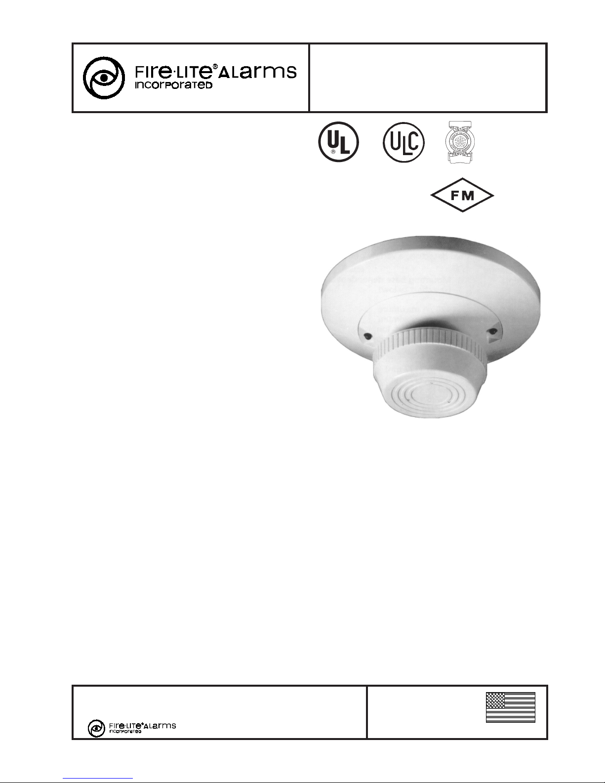
Ionization Smoke Detector
Section: Conventional Initiating Devices
F-555
1451
2-Wire and 4-Wire
GENERAL
The System Sensor 400 Series plug-in ionization smoke detectors respond quickly to both fast flaming and slow smoldering fires as required by UL 268. Unipolar dual chamber sensor has the sensitivity needed to quickly detect smoke, and
the stability needed to avoid false alarms.
FEATURES
Unique dual unipolar sensor:
Provides exceptional stability.
Factory preset at 1.9% nominal sensitivity.
Stable operation up to 1,200 feet per minute (6 meters
per second) air velocities.
Removable cover for field cleaning.
Two visible LEDs blink in standby.
Sealed against dirt, insects, and back pressure.
Three-year limited warranty.
Field metering of detector sensitivity.
Built-in test switch.
Low standby current.
Built-in tamper-resistant feature.
Designed for direct surface or electrical box mounting.
360° field viewing angle of the visual alarm LEDs.
Insect-resistant screening (0.020"/0.508 mm openings).
Easy plug-in of the head to base.
SEMS screws for easy wiring.
Optional recess mounting.
Field-adjustable sensitivity.
APPLICATIONS
Use to contribute to life safety, fire protection, and property
conservation. Superior to photoelectric detectors in detecting
fast-flaming fires. Superior to bipolar detectors in avoiding
false alarms.
CONSTRUCTION & OPERATION
All 400 Series plug-in ionization smoke detectors contain a
unique dual-source, dual unipolar chamber detection design
which will sense the presence of smoke particles produced by
fast combustion as well as slow smoldering fires. Additional
key features include a blinking LED standby status indicator,
an easily visible alarm indication, and provision for convenient
field test and metering.
The back of the detector is sealed to block back-pressure air
flow. The chamber is protected by a fine mesh (0.020"/0.508
mm) screen to minimize problems with dust, dirt, and insects.
If cleaning is required, it is easy to remove the cover (with a
special tool) and obtain access to the screen and chamber to
perform a thorough cleaning.
INSTALLATION
Model 1451 detectors are intended for use with FireLite ULlisted control panels. Maximum number of detectors per zone
California
State Fire
Marshal
7271-1209:126
S911
CS308
BSA
1202-88-SA
1451
is listed in the installation manual for each control panel. Easy
to install and maintain, this detector is designed for direct surface mounting (using one of the B400 Series bases listed below. Easy-to-wire screw terminals allow fast and simple field
wiring of IN, OUT, and remote annunciator connections.
Consult FireLite control panel specifications for the maximum
allowable loop resistance for the particular control panel to be
used.
To prevent wiring mistakes, observe polarities and make certain that each conductor is identifiable. A copy of Installation
and Maintenance Instructions is packaged with each detector.
For further information, refer to NFPA 72 Standard on Automatic Fire Detectors.
A MOUNTING BASE SELECTION GUIDE is included on page
2 of this document.
JUNCTION BOX SELECTION GUIDE: Box depth is contingent on base and wire size. Refer to National Electrical Code
or local applicable codes for appropriate recommendations.
Bases B401 and B401B can utilize a single-gang, 3-1/2" (88.9
mm) octagonal, 4" (101.6 mm) octagonal, or 4" square junction box. Bases B402B and B406B can utilize a single-gang,
3-1/2" octagonal, 4" octagonal, 4" square, 50 mm, 60 mm, or
75 mm junction box. Base B404B can utilize a 4" octagonal
or 4" square junction box.
0Q1A0.AY
This document is not intended to be used for installation purposes. We try to keep our
product information up-to-date and accurate. We cannot cover all specific applications or
anticipate all requirements. All specifications are subject to change without notice. For
more information, contact FireLite. Phone: (203) 484-7161 FAX: (203) 484-7118
12 Clintonville Road, Northford, Connecticut 06472
ISO-9001
Engineering and Manufacturing
Quality System Certified to
International Standard ISO-9001
Made in the U.S.A.
DF-50475 Page 1 of 2
Page 2
GENERAL SPECIFICATIONS
Operating voltage: mounting base dependent (see chart
below).
Standby current: 120 micro amps.
Sensitivity: 1.9% nominal.
Weight: 0.6 pounds (272 grams).
Size: 3.2" (81.28 mm) high; 4.0" (101.6 mm) diameter with
unflanged bases, or 6.2" (157.48 mm) diameter with flanged
bases.
Construction: Flame-retardant white Noryl® plastic.
Temperature: 32°F to 120°F (0°C to 49°C).
Humidity range: 10 to 93% R.H. (non-condensing).
Maximum air velocity: 1,200 feet per minute (6 meters
per second).
PRODUCT LINE INFORMATION
Model Description
1451 Ionization Detector. Must be mounted to one of
the B400 Series Bases listed below.
RA400Z Remote Annunciator for 2- or 4-wire applica-
tions. Use with any System Sensor 400 Series
plug-in detector. Fits standard U.S. single-gang
electrical box.
MOD400R Field Test module for all of the System Sensor
400 Series Smoke Detectors.
ss
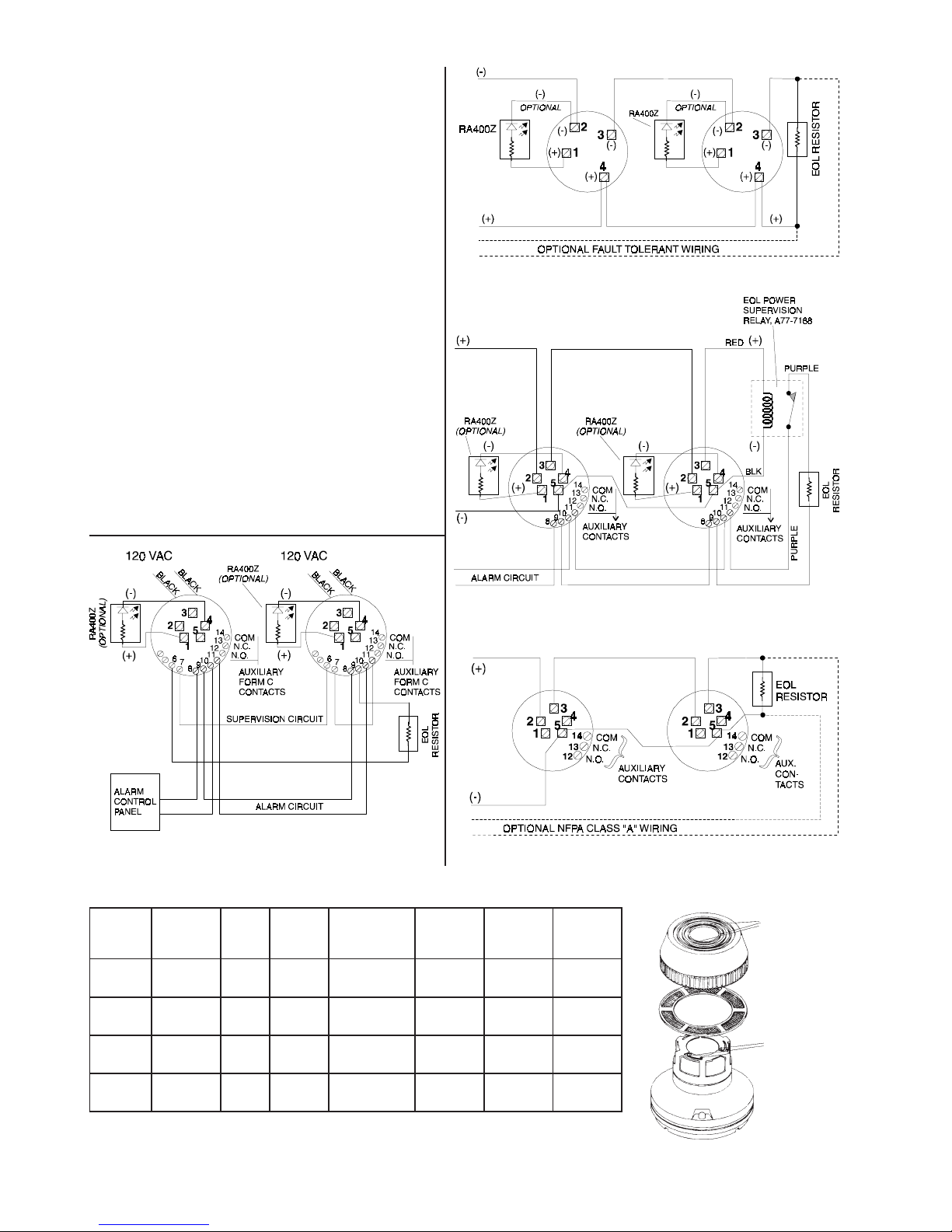
s B401B/B401 Wiring Diagram
ss
ss
s B404B Wiring Diagram
ss
MOUNTING BASE SELECTION GUIDE
esaB
ledoM
rebmuN
&104B
B104B
B204B CLU&LUeriw-4seYC-&A-mroFCDV42
B404B CLU&LUeriw-4seY
B604B
noisreV
/CLU/LU
45-NE
/CLU/LU
45-NE
pooL
epyT
*eriw-2oN CDV42/21
*eriw-2oNC-mroFCDV42
tnerruC
timiL
rotsiseR
mralA
tcatnoC
epyT
A/C-&A-mroF
yrosivrepuS
lanimoN
egatloV
CAV021CAV021
ss
s B402B Wiring Diagram
ss
ss
s B406B Wiring Diagram
ss
ybdnatS
egatloV
53ot5.8
CDV
23ot71
CDV
23ot51
CDV
tnerruC
warD
mralAno
001ot01
**Am
93ot41
Am
CAAm57
mumixam
001ot21
**Am
Location of
holes to access
and release
locking prongs.
Cover and
screen are
removable
for cleaning.
Locking
prongs.
*Functionality contingent on panel compatibility. **Must be limited by control panel.
RELAY CONTACT RATINGS: Resistive or Inductive (60% power factor load). Form-A: 2.0 A at
30 VAC/DC. Form-C: 0.6 A at 110 VDC, 2.0 A at 30 VDC, 1.0 A at 125 VAC, 2.0 A at 30 VAC.
Page 2 of 2 DF-50475
 Loading...