

Firegear Sanctuary Series, SAN2-34DBSAWSN Series, FPB-26DBSAWS-N-SAN, FPB-34DBSAWS-N-SAN, Sanctuary 2 Installation And Operating Instructions Manual
...
DO NOT DISCARD. THIS MANUAL
HAS IMPORTANT OPERATING AND
MAINTENANCE INSTRUCTIONS.
LEAVE WITH THE HOMEOWNER.
MODEL:
SERIAL #:
THE ROUND FLAT DISC SYSTEM FOR THE SANCTUARY 2 & 3 COMES
WITH A SEPARATE CARTON AND MANUAL. HOWEVER, USE THIS
MANUAL FOR ACTUAL INSTALLATION INTO THE SANCTUARY BOWLS
Sanctuary 2
Sanctuary 3
MODELS
Natural Gas Description
SAN2-34DBSAWSN-*
SAN3-26DBSAWSN-*
* Bowls come in a variety of colors. (i.e. SAN2-34DBSAWSN-AR) Your color will
be denoted at the end of the model number with one of the following letters:
AR = Arctic; CR = Creme; MO = Mocha; SL = Slate; RA = Raven
38 ¾” x 18” Concrete Bowl
30” x 14 ½” Concrete Bowl
Sanctuary Series Outdoor Fire Features
(All Weather Electronic Ignition System (AWS)
Installation and Operating Instructions
IF YOU CANNOT READ OR UNDERSTAND THESE INSTALLATION INSTRUCTIONS
DO NOT ATTEMPT TO INSTALL OR OPERATE THIS APPLIANCE
All Sanctuary Series Fire Features have
18-square inches of ventilation designed into each bowl.
Warning: For Outdoor Use Only
REV. 8-9-19 Page 1
CARBON MONOXIDE HAZARD
DANGER
This appliance can produce carbon monoxide
which has no odor.
Using it in an enclosed area can kill you.
Never use this appliance in an enclosed
space such as a camper, tent, car or home.
DANGER
If you smell gas:
1. Shut off gas to the appliance
2. Extinguish any open ame.
3. If odor continues, keep away from
the appliance and immediately call
your gas supplier or re department.
WARNING
Do not store or use gasoline or other
ammable vapors and liquids in the
vicinity of this or other appliances.
Any LP cylinder not connected for use
shall not be stored in the vicinity of this
or other appliances.
WARNING
Do not leave unattended during use.
WARNING
Do not use for cooking.
Follow all gas leak procedures in this
manual prior to operation.
Improper installation, adjustment,
alteration, service or maintenance
can cause injury or property damage.
Read the installation, operating and
maintenance instructions thoroughly
before installing or servicing this
equipment.
WARNING
If the information in these instructions is not followed exactly, a re or explosion
may result causing property damage, personal injury or death.
FOR YOUR SAFETY
Do not store or use gasoline or other ammable vapors and liquids in the vicinity
of this or other appliances.
Fuels used in gas red appliances, and the products of combustion such as fuels, contain
chemicals known to cause cancer, birth defects and/or other reproductive harm.
This warning is issued pursuant to the California Health & Safety Code Sec. 25249.1
AWS Sanctuary 2 & 3 Fire Features
REV. 8-9-19 Page 2

CALIFORNIA PROPOSITION 65
All media (i.e. lava rock, lava stones, lava boulders and re glass) has the potential of thermal
spalling. This is a process that may occur when media is wet and moisture gets trapped inside of
the material due to rapid temperature differences. When this happens the media has the potential
to crack or “pop” outside the replace.
WE HIGHLY RECOMMEND COVERING ALL FIRE FEATURES WHEN NOT IN USE
The use of a cover can lessen the impact of thermal spalling; however, heavy rains, high
humidity and the presence of moisture may still cause the media to pop.
ALWAYS USE CAUTION WHEN USING THE FIRE FEATURE
Extra caution should be taken when lighting a re feature after heavy rains, high humidity and
moisture are present. Light the re feature; leave the area allowing any moisture in the media to
dissipate. We strongly recommend that during this drying out time that you monitor the re feature
from a distance. This drying out period should be no less than 30 minutes. Continue monitoring
the ame from distance to ensure that all popping has ceased before fully enjoying the re.
WARNING
This product is designed to operate with one of the following fuel sources: Liquid Propane or Natural Gas. The fuel used to
operate this product, and the products of combustion of such fuel, can expose you to chemicals including Benzene which
is known to the State of California to cause cancer, birth defects and other reproductive harm and Carbon Monoxide which
is known to the State of California to cause birth defects or other reproductive harm.
(For more information go to: www.p65Warnings.ca.gov.)
TABLE OF CONTENTS
Specications 4
Preparing a Location for Your Sanctuary Fire Feature 5
Hard Piping to Fire feature 5
Ventilation Information 5
High Elevation 5
Gas Pipe Sizing Chart 6
Installation Requirements of Fire Feature 7
Typical Installation Drawings 8
Installing Pan into Bowl & Wiring 9
Installation of Lava Rock/Media 11
Media Specications 11
Expanded view of Sanctuary 2 10
Operation 12
Lighting Instructions 12
Replacement Parts 13
Replacement Parts List 14
Maintenance 15
Trouble Shooting 16-18
Optional Accessories 19
Warranty 20
Technical Support 22
AWS Sanctuary 2 & 3 Fire Features
REV. 8-9-19 Page 3

SANCTUARY SPECIFICATIONS
F
E
G*
A
B
C
D
TOP VIEW
4-inch
Diameter
Model:
Natural Gas (NG)
SAN2-34DBSAWSN- FPB-34DBSAWS-N-SAN 38¾” 35¼” 2” 18” 19” 69”
SAN3-26DBSAWSN- FPB-26DBSAWS-N-SAN 30” 27½” 2” 14” 19” 69” 12”
Table 1 Sanctuary Specications
* Dimension shows disc/pan from combustible oor sitting inside the Sanctuary bowl (See Fig. 2).
Uses Fire feature Model:
A
Overall
Width
B
Inside
Width
C
Inside
Depth
D
HeightESide
Wall
F
Combustible
Ceiling
Combustible
Floor
15 1/2”
G*
Fig. 1 Sanctuary Dimensions
(SAN2- lower base is 18” wide x 1½” tall)
(SAN3- lower base is 14½ wide x 1¼” tall)
Model:
Natural Gas (NG)
SAN2-34DBSAWSN- #29 65,000
SAN3-26DBSAWSN- #29 65,000
Table 2 Btu Specications
Disclaimer: Btu listings are based on 7.0”WC for Natural Gas and 11.0”WC for Liquid Propane (LP)
to the gas valve. Flex line size and proper gas pipe sizing will also affect Btu’s. As a result your Btu’s
may vary slightly from Table 2 specications.
WARNING: Proper clearances from combustible materials must be maintained from all sides, top
and bottom of this appliance. Use the specications listed for proper clearance to combustibles.
AWS Sanctuary 2 & 3 Fire Features
NG Factory
Orice
NG
Btu’s
Fig 2. Clearance to Combustibles
(Not to be used in an enclosed space)
Pressure NG LP
Min. Inlet 3.5” WC (⅛ PSI) 8.0” WC (¼ PSI)
Max. Inlet 14.0” WC (½ PSI) 14.0” WC (½ PSI)
Normal Inlet 7.0” WC (¼ PSI) 11.0” WC (⅜ PSI)
Table 3 Gas Pressures
REV. 8-9-19 Page 4

PREPARING A LOCATION FOR FIRE FEATURE
LP
Gas
Hard Pipe
Access
Top View
FG-12QDK
4”
(Min. distance
from tank)
60”
NOTE: The Sanctuary Series re features/bowls are constructed of Glass Fiber Reinforced Concrete (GFRC). The
Sanctuary 2 weighs 166 LBS without media or the burner system installed. The Sanctuary 3 weighs 92 LBS without
media or the burner system installed. Ensure the structure you are placing these re features on is solid enough to
securely hold the weight. IT IS HIGHLY RECOMMENDED FOR AT LEAST 2-3 PEOPLE TO ASSIST IN MOVING THE
FIRE FEATURES INTO PLACE.
Install the re features on any level, at, stable, non-combustible surface. NOTE: Do not place re features directly on
grass, dirt, or rocks as this may prevent proper ventilation. Water drainage is designed into all Sanctuary Series re
features. Ensure not to block/plug the drains areas to prevent potential damage to your re feature.
Any installations within 5-feet of a pool or spa will require a FG-PS30V320 power supply. See separate
manual and accessory page for details or call Technical Service department.
The Sanctuary 2 and 3 can be plumbed with either Natural or Propane (LP) gas. See Fig. 3. If you choose to run hard
pipe to Sanctuary models, enter through center (bottom) of the bowl; protrude pipe no higher than 6” above ground level.
Note: Due to space limitations, the Sanctuary 3, cannot accommodate a 120VAC (GFI box) and 1420-AOD remote
control weatherproof box inside the bowl. These components will have to be wired externally, outside the bowl.
A recommendation would be to place the Sanctuary 3 on a pedestal or base then install the GFI box and remote
control receiver inside the pedestal or base.
HARD PIPING TO FIRE FEATURE WITHOUT GAS PROXIMITY
NOTE: Refer to the NFPA54 (National Fuel Gas Code) for proper pipe sizing. See gas line sizing chart on page 6 of this
manual as a reference.
1. Turn OFF gas supply system. NOTE: All gas connections (except for brass to brass) require the following. Clean pipe
threads using either a wire brush or steel wool. Apply pipe sealant to the ttings before making any connection.
2. BE CAREFUL! Ensure all gas connections are snug, but do not over tighten!
3. Consult a plumber for proper installation to ensure you are providing adequate gas supply for your application.
4. The primary gas shut-off (not supplied) will require a ⅜” male ared tting to enable connection of the stainless steel
ex gas line supplied with the re feature.
FLEXIBLE PIPING TO FIRE FEATURE
1. Do not place an LP tank inside any re feature enclosure. Locate all propane (LP) tanks outside the enclosure inside
an approved separate enclosure a minimum of 60” from the Sanctuary Series. Flex line can run through any vent
holes. If using Propane gas an FG-LPRK regulator (not included) must be used and a FG-12QDK quick disconnect kit
(not supplied) enables the use of a Propane (LP) gas tank connection. See Fig. 3.
Fig 3. Shows gas line using an LP quick disconnect or hard piped with Natural gas.
HIGH ELEVATION INSTALLATION
This appliance is listed for elevations from 0-4500 feet in Canada and the U.S. If elevation exceeds 4500 feet it may be
necessary to decrease the input rating by changing the existing burner orice to a smaller size. Input should be reduced
4% for each 1000 feet beyond the 4500 feet above sea level. Check with your local gas utility for assistance in
determining the proper orice in your location. In some cases the heating value may already be reduced and downsizing
the orice may not be necessary. Refer to NFPA 54 Table E.1.1(d) for high altitude orice sizing.
AWS Sanctuary 2 & 3 Fire Features
REV. 8-9-19 Page 5

REFERENCE
GAS PIPE SIZING
Length of Pipe in Feet
1/2” 3/4” 1” 1 - 1/4” 1 - 1/2” 2” 2 - 2 1/2” 3” 4”
10 275 567 1071 2205 3307 6221 10140 17990 35710
20 189 393 732 1496 2299 4331 7046 12510 25520
30 152 315 590 1212 1858 3465 5695 10110 20620
40 129 267 504 1039 1559 2992 4778 8481 17300
50 11 4 237 448 913 1417 2646 4343 7708 15730
60 103 217 409 834 1275 2394 3908 6936 14150
70 89 185 346 724 1086 2047 3329 5908 12050
80 78 162 307 630 976 1811 2991 5309 10830
90 69 146 275 567 866 1606 2654 4711 9613
100 63 132 252 511 787 1496 2412 4281 8736
125 54 112 209 439 665 1282 2083 3618 7382
150 48 100 185 390 590 1138 1808 3210 6549
175 43 90 168 353 534 1030 1637 2905 5927
200 40 83 155 325 491 947 1505 2671 5450
300 37 77 144 303 458 887 1404 2492 5084
NATURAL GAS : PIPE SIZING CHART
•
Natural Gas (NG) flow is given in
thousands of BTU/hr. = 1 cubic
foot of NG gas - 1000 BTU
•
Nominal pressure at the burner
for Natural Gas is 3.5” of water
column. (Typical machine supply
5”-7”)
•
Pipe length must include
additional length for all fittings.
Add approximately 5 feet of pipe
per fitting.
•
Natural Gas Example: A machine
with a burner that requires
440,000 BTU would need a 1 -1/4”
pipe for a 20” long run.
LIQUID PROPANE : PIPE SIZING CHART
NOTE: The sizing charts above list the specific pipe sizes required for the amount of BTU’s for a new gas line installations. If you
are using an existing gas line you must take into consideration the existing gas line capacities to ensure you will have proper
pressure. This chart is for reference only, we recommend you consult with a Licensed Plumber/Gas Fitter or NFPA54 (National Fuel
Gas Code - current edition) for more details.
Length of Pipe in Feet 1/2” 3/4” 1” 1 - 1/4” 1 - 1/2” 2” 2 - 2 1/2” 3” 4”
10 108 230 387 793 1237 2259 3640 6434 -
20 75 160 280 569 877 1610 2613 5236 9521
30 61 129 224 471 719 1335 2165 4107 7859
40 52 11 0 196 401 635 1143 1867 3258 6795
50 46 98 177 364 560 1041 1680 2936 6142
60 42 89 159 336 513 957 1559 2684 5647
70 38 82 149 317 476 896 1447 2492 5250
80 36 76 140 239 443 840 1353 2315 4900
90 33 71 133 275 420 793 1288 2203 4667
100 32 68 126 266 411 775 1246 2128 4518
125 28 60 11 7 243 369 700 1143 1904 4065
150 25 54 105 215 327 625 1008 1689 3645
175 23 50 93 196 303 583 993 1554 3370
200 22 47 84 182 280 541 877 1437 3160
300 17 37 70 145 224 439 686 1139 2539
•
Liquid Propane (LP) Gas flow is
given in thou sands of BTU/hr. =
1 cubic foot of LP gas - 2500 BTU.
•
This chart refers to low pressure LP,
after regulation, Standard nominal
pressure at the burner for Liquid
Propane Gas is 11” of water column.
•
Pipe length must include additional
length for all fittings. Add
approximately 5 feet of pipe per
fitting.
•
LP Example: A machine with a
burner that requires 440,000 BTU
would need a 1” pipe for a 20’ long
run.
GAS PIPE SIZING CHART
Table 4 Gas Pipe Sizing Chart
AWS Sanctuary 2 & 3 Fire Features
REV. 8-9-19 Page 6

PRE-INSTALLATON CHECK LIST FOR SINGLE INSTALL
GAS INFORMATION
Gas Volume - Ensure the correct size pipe is used for
the total gas load. If installing more than one re feature,
ensure the correct size pipe is based upon the distance of
the furthest re feature away and the total gas load is for
all gas appliances on that gas line (i.e. re feature, BBQ,
torches, etc.).
Gas Pressure & Type of Gas - Verify the gas pressure
being supplied to the re features? Is the re feature(s)
congured for the proper gas type? The AWS gas valve is
shipped for Natural gas (NG). To convert to Propane (LP)
gas, the secondary pilot orice must be changed.
Manual Shut-off/Key Valve - A manual shut-off or key
valve installed into of the re feature?
Purging a New Gas Line - Has the gas line been purged
of both air and possible debris? Any gas lines buried
underground must be pressure tested up to 60PSI to
ensure no leaks. After inspection is complete, most
plumbers will release pressure in the line at one location by
opening the manual ball/key valve. It is recommended to
release pressure by opening a ball/key valves associated
with all the re features. Example: There are four re
features on a job, open the rst key valve for a few
seconds, then close it. Then move on to the next key valve
and do the same thing until you have purged the debris out
of all four gas lines.
Main Burner Orice - All re features MUST have a main
burner orice installed on the inlet side of the burner. An
orice limits the amount of gas ow to the burner to
ensure the ame is a safe and reasonable height to not
pose a risk to people or property. The drawings below show
the difference between a Natural Gas (NG) and Propane
(LP) orice. LP gas requires ventilation holes at the base
of the orice to provide a cleaner ame. See Fig. 3.
ELECTRICAL INFORMATION
Wire Gauge - Is the wire gauge correct? Wiring must be
12AWG or greater (solid or stranded) for all installations.
Note: It is recommended to ll the wire nuts with either
dielectric grease or silicone prior to installing the wire nut.
This will ensure a waterproof connection.
Why GFI circuit? A GFI is a type of circuit breaker which
shuts off electric power when it senses an imbalance
between the outgoing and incoming current. It protects the
house wires and receptacles from overheating and possible
re.
Power Supply - Firegear Outdoors provides one
GOE-30VDC power supply with each Sanctuary model.
The power supply requires 120VAC power to operate and
converts it to 30VDC to operate the gas valve. DO NOT
CONNECT 120VAC DIRECTLY TO THE GAS VALVE
WIRES - DAMAGE WILL OCCUR. THIS IS NOT
COVERED BY WARRANTY. The #GOE-30VDC is used
for one re feature only and must be installed 10-feet or
greater from any pool or spa. This power supply has a
3-foot power cord to plug into 120VAC outlet and a 3-foot
leads to connect to the gas valve on the 30VDC side.
MEDIA INFORMATION
Acceptable media placed over top of the burner:
Lava Rock Min.1”- 2” size
FG-LAVA-10 (10 LBS.)
FG-LAVA-50 (50 LBS.)
GL Glass Min. ½” - ¾” size
Various colors are available
See Product catalog for details
Sold in 5 LB. bags or 8 bags to a
case
GRL Reflective Glass Min. ½” - ¾” size
Various colors are available
See Product catalog for details
Sold in 5 LB. bags or 8 bags to a case
NG LP
Fig. 4 Natural (NG) orice on left; LP (vent holes) on right.
AWS Sanctuary 2 & 3 Fire Features
DRAINAGE INFORMATION
For any fire feature ABOVE ground level requires a drain/
holes line or a way for water to exit the fire feature.
Note: This AWS system is not approved to be installed
BELOW ground level.
REV. 8-9-19 Page 7

INSTALLATION REQUIREMENTS OF ALL FIRE FEATURES
REQUIREMENTS
1. This re feature is permitted to be placed on a stable, at combustible surface. The area underneath must be a solid level
surface maintaining clearances according the specications in this manual on page 4.
2. Refer to the NFPA54 (National Fuel Gas Code) for proper pipe sizing. See Table 4 on page 6.
3. Determine the model re feature you are preparing to install (Refer to page 4).
4. Follow the local code requirements for the gas type being used. This re feature should be installed in accordance
with local codes and ordinances or in the absence of local codes, with the latest National Fuel Gas Code, ANSI
Z223.1 NFPA54 or CSA B149.1, Natural and Propane Installation Code in Canada.
5. Fire features create high temperatures, it is very important to have any combustibles at a safe distance.
6. These re features are designed for outdoor use only. Not approved for any indoor use.
7. This re feature is designed to have lava rock completely covering the spur burner, so that the burner is not visible.
Do not cover more than 1” above the top of the covered burner. When purchasing Lava Rock use a minimum of 1 to
2-inch diameter as a base to ll the burner pan. DO NOT COVER THE IGNITION HOOD WITH ANY ROCK OR MEDIA.
8. Gas lines and ttings must be installed in to the non-combustible structure. All gas connections must be leak tested
before installation of the re feature. Soapy water leak detection is required before regular use of the re feature.
9. Do not use material that will absorb moisture over time and will not release this moisture quickly. Moisture can boil
in this material and can rapidly break apart and cause damage or personal injury.
10. Never leave any other combustible material on top of the re feature. This could cause unsafe operation of this
system and damage to the component that will not be covered under our warranty.
11. Ventilation is built into the bottom of each concrete re feature. No additional vents are required. WARNING: DO
NOT BURY THE BOTTOM OF THE CONCRETE BOWL INTO EARTH OR OTHER TYPE OF MEDIA . THIS CAN
OBSTRUCT AIR FLOW VENTILATION AND VOID FIREGEAR WARRANTY.
IMPORTANT
Installation of Natural or LP gas should be done by a qualied installer, service agency or gas supplier.
The appliance and its manual shutoff valve must be disconnected from the gas supply piping system during any
pressure testing of the system at test pressure testing of the system at test pressures in excess of ½” psig (3.5kPa).
DESCRIPTION
The Sanctuary series features a eld serviceable (30VDC) commercial grade outdoor electronic system with a
maximum gas capacity of 290,000 Btu’s. The system features a built-in safety shut-off in case of ame loss and
auto-relight. It is shipped as a Natural Gas (NG) model only and must be converted if using Propane (LP) gas. The AWS
burner pan comes pre-assembled with the bowl and include a key valve with mounting plate ready to install.
Preparation for the AWS model: The Sanctuary 2 requires additional preparation and planning. The gas line and
power must be predetermined before installing. The AWS model requires a 120VAC Ground Fault Interrupter (GFI) to be
installed inside the bowl in a weatherproof box before installing the re pit (except for the Sanctuary 3).
The Sanctuary 3 is too small to “house” the remote control with weather proof box and the 120VAC GFI outlet. They will
have to be installed somewhere outside the bowl. It is recommended to install the Sanctuary 3 on top of a pedestal then
install the 120VAC GFI power and remote control inside the pedestal.
Ensure you follow all local codes. In the absence of local codes use the latest edition of the National Fuel Gas Code
NFPA 54 and National Electrical Code (NEC), or NFPA 70. The remote control weatherproof box (supplied) should be
mounted securely in close proximity of the GFI box. The GFI box will power the adapter and the remote control receiver.
See AWS expanded view drawing as a guide on page 12.
AWS Sanctuary 2 & 3 Fire Features
REV. 8-9-19 Page 8

SANCTUARY (AWS) PREPARATION
49-88
(BRASS ELBOW)
CRV-BVL2CP
BVL2S
(Key Valve)
MT-FACEPLATE
49-88
(BRASS ELBOW)
TOP VIEW
KEY VALVE ASSEMBLY
The gure drawing below shows the MT mounting plate
parts and pieces used for the assembly. This is preassembled and ready to install. See Fig. 5. The Key Valve
Assembly consists of (1) key valve and ange, (2) 90°
elbows and (1) MT stainless steel face plate.
MT Mounting
Plate Detail
Fig. 5 Assembled MT mounting plate.
INSTALLATION OF MT MOUNTING PLATE
Install the key valve mounting plate into the Sanctuary bowl
as shown in Figs. 6 & 7. The mounting plate must be
oriented with key valve at the top (closest to burner pan).
Use the four (4) thread cutting screws (supplied) to secure
the mounting plate into the bowl.
AWS Sanctuary 2 & 3 Fire Features
Fig. 6 Typical MT installation.
Install valve mounted
from front as shown.
Fig. 7 Top view of MT mounting plate into bowl.
REV. 8-9-19 Page 9
LEARN
Weather
Proof
Box
AWS
Valve Box
GFI Box
+
-
+
GOE-30VDC
Power Supply
FG-1420-AOD
Receiver
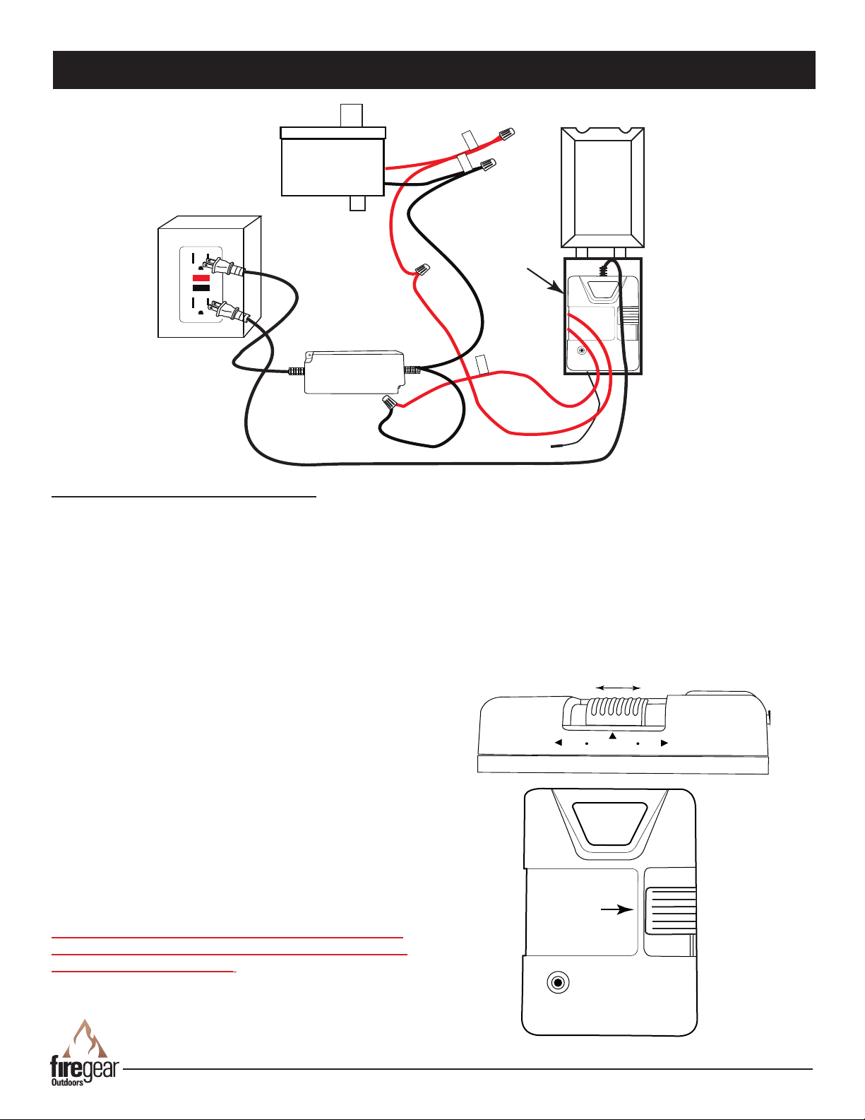
Fig. 8 Wiring diagram.
ON
REMOTE
OFF
INSTALLING PAN INTO BOWL & WIRING
INSTALLING BURNER PAN INTO BOWL
After the mounting plate is secured inside the bowl,
attach a ex line to the bottom tting of the mounting plate
and the other end to the primary gas supply.
Install the GOE-30DCV power supply and FG-1420-AOD
remote control as shown in the wiring diagram (Fig 8).
Note: Ensure the external antenna on the FG-1420-AOD
receiver is outside the junction box.
This is a polarity sensitive system. There is a red sleeve
attached to the positive (+) side of the DC power supply.
When wiring the remote control receiver, cut off both 1/4”
terminals and strip both wire ends. Connect one red wire
from the receiver to the GOE-30DCV power supply with
the red sleeve; secure with wire nut. Connect the other red
wire from the receiver to the + (positive) directly to the red
wire from the gas valve control box; secure with wire nut.
See Fig. 8.
Note: An extra red jumper wire is provided to extend either
one of the red wires of the FG-1420-AOD remote control
receiver (if needed). It is not required to use this wire. It
depends on each application.
DO NOT CONNECT 120VAC DIRECTLY TO THE GAS
VALVE WIRES -DAMAGE WILL OCCUR. THIS IS NOT
COVERED BY WARRANTY.
AWS Sanctuary 2 & 3 Fire Features
Note: Use dielectric grease inside of all wire nut
connections to protect from the outside elements.
Plug the GOE-30VDC power supply and remote receiver
into the 120VAC GFI box. Install battery into the
transmitter of the FG-1420-AOD and “learn” (program)
the receiver to the transmitter. Ensure the slide switch on
the receiver is in the REMOTE position See Fig. 9; Press
and Release the “learn” button on the receiver. You will
hear the receiver emit a short “beep”. Once this occurs,
press any button on the transmitter and the receiver will
emit several rapid beeps conrming the two are programed
together.
Slide
Switch
LEARN
Fig. 9 1420-AOD slide switch and learn button.
REV. 8-9-19 Page 10

Concrete Tab
Mesh Pilot Hood
Media
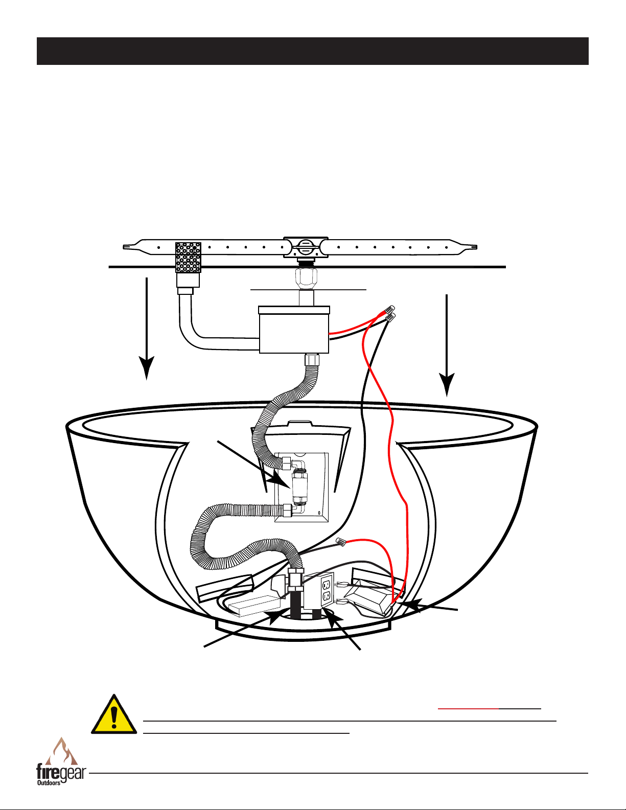
INSTALLING PAN INTO BOWL & WIRING
Attach another ex line to the top tting and connect the
other end to the ared tting of the gas valve box.
Securely tighten all ttings. Install the assembled pan into
the bowl as shown in Fig. 10 resting the pan on the
concrete tabs, centered, inside the bowl.
Fig. 10 Installing burner assembly into the bowl.
MEDIA PREPARATION
MEDIA SPECIFICATIONS
The Sanctuary 2 and 3 models are approved for use with
Firegear Outdoor lava rock.
• Sanctuary 2 uses 57 LBS of Firegear Outdoor lava rock
• Sanctuary 3 uses 24 LBS of Firegear Outdoor lava rock
Lava rock height should be level and no higher than the top
lip of the bowl (approximately 2“ depth from burner pan).
Fig. 11 MedIa (lava rock) installation.
INSTALLATION OF MEDIA INTO BURNER PAN
Install lava rock into the burner pan. Ensure the lava rock is
a minimum of 1-inch diameter for proper operation.
Note: Do not pour Lava Rock directly from bag. It should
be placed naturally and NOT packed in tight. Loose tting
is important to ensure robust ames. Be sure rocks are
free of any excessive dust. This prevents the burner pan
weep holes from being plugged and holding water.
IMPORTANT: Do not place rock over top or under the
screen cover. The screen must be free of any debris to
ensure proper lighting of burner (See Fig. 12).
Cover the burner completely with media but do not make
the depth greater than 1-inch overtop of the burner
port holes.
Do NOT cover the top of mesh pilot hood with any rock or
glass. It must be free an any debris to operate properly.
Fig. 12 Media placement around pilot hood.
AWS Sanctuary 2 & 3 Fire Features
REV. 8-9-19 Page 11
AWS EXPANED VIEW
Hard Pipe
Gas Supply
Key Valve
AWS Burner Pan Assembly
V
e
n
t
Remote
Power
Supply
GFI Box
Remote
Receiver
(w/weather
proof cover)
Note: The gas supply may be hard piped into the center of the bowl or an approved
exible gas line can be installed through one of the lower vents.
The installation shown above is a Sanctuary 2 Fire Feature; The Sanctuary 3 does not
have enough room for the GFI power box and the FG-1420-A OD remote receiver; they will
require external mounting outside of the bowl.
AWS Sanctuary 2 & 3 Fire Features
REV. 8-9-19 Page 12

AWS OPERATION
CAUTION: Children and adults should be alerted to the hazards on high surface temperatures and should stay away to
avoid burns or clothing ignition. Young children should be carefully supervised when they are in the area of the appliance.
WARNING: Do not use this appliance if any part has been under water. Immediately call a qualied service technician
to inspect the appliance and to replace any part of control system and any gas control, which has been under water.
SAFETY WARNINGS
1. Never leave the re pit unattended during operation.
2. Clothing or other ammable materials should not be placed on or near the appliance.
3. Any guard or other protective device removed for servicing the appliance must be replaced prior to operating the
appliance.
4. Installation and repair should be done by a qualied service person. The appliance should be inspected before
use and at least annually by a qualied service person. More frequent cleaning may be required as necessary. It
is imperative the control compartment, burners and circulating air passageways of the appliance be kept clean.
5. Inspect the fuel supply connection before each use of the appliance.
6. Temporary storage of this appliance indoors is permissible only if it has been disconnected from its fuel supply
(Natural or LP gas line).
WARNING
1. This appliance is hot when operated and can cause severe burns if contacted.
2. Do not burn any solid fuels in this appliance.
READ ALL LIGHTING INSTRUCTIONS BEFORE ATTEMPTING TO LIGHT FIRE PIT
CAUTION: ENSURE YOU HAVE LEAK TESTED THE FIRE PIT BEFORE OPERATING AND THE TRANSMITTER AND
RECEIVER HAVE BEEN “LEARNED”(PROGRAMED TOGETHER) FOR WIRELESS OPERATION.
WARNING: Do not stand overtop of re feature during ignition or operation due to high surface temperatures.
LIGHTING INSTRUCTIONS
TURNING ON FIRE FEATURE
Prior to turning the re feature ON, visually inspect the re pit to ensure debris such as leaves or other combustible
materials have not collected on top of the re feature, which could burn and emit embers once the re feature is turned
ON. At the same time, ensure anyone standing close to the re feature is aware you are turning it ON and steps away, at
a safe distance prior to lighting.
The ignition sequence is as follows:
1. Turn the manual key valve to the ON position.
2. Turn the re feature ON by pressing the ON button of the remote control. The hot surface ignitor will heat up and
begin to “glow” within a 10 second period.
3. Once the hot surface ignitor heats up, the pilot gas valve opens, a “click” is heard, and gas is released to the burner,
lighting the re feature.
The entire ignition sequence ignites within 20 seconds or less. If not, press the OFF button on the remote control and
wait 5 minutes before trying again.
TURNING OFF FIRE FEATURE
1. Turn the re feature OFF by pressing the OFF button on the remote control.
2. If you are no longer burning the re feature until another time, we recommend turning the key valve to OFF position.
AWS Sanctuary 2 & 3 Fire Features
REV. 8-9-19 Page 13

Junction Box
Weatherproof
Cover/Lid
GOE-30DCV
SANCTUARY 2 & 3 REPLACEMENT PARTS
OUT
10
1
9
4
Drawings No to Scale
8
11
7
2
3
5
6
13
12
14
17
20
15 16
18
21
19
22
AWS Sanctuary 2 & 3 Fire Features
REV. 8-9-19 Page 14

SANCTUARY 2 & 3 REPLACEMENT PARTS LIST
OUT
Item
1 34-inch round at stainless disc (used with Sanctuary 2 model) 1 PAN-SS34D
1 26-inch round at stainless disc (used with Sanctuary 3 model) 1 PAN-SS26D
2 22-inch Spur Burner (used with Sanctuary 2 re feature) 1 B-SPUR-22
2 16-inch Spur Burner (used with Sanctuary 3 re feature) 1 B-SPUR-16
3 Sanctuary 2- 38¾” Diameter Concrete Bowl 1 SANCTUARY2
3 Sanctuary 3 - 30” Diameter Concrete Bowl 1 SANCTUARY3
4 Mounting Nut ½” NPS Brass Nut 2 105-8
5 ⅞” Flat Mounting Washer 1 ST3-113-1026
6 ½” Flex Non-Whistling Gas Line 22” Long 1 T-200-9898-22
7 MT Face Plate 1 MT-FACEPLATE
8 Chrome Flange (decorative ange used with BVSL2S) 1 CRV-BVL2CP
9 Key Valve 1 BVL2S
10 ½” Flare x ½” MIP Brass Elbow (used with BVL2S - MT models) 2 49-88
11 Air Shutter Orice Natural Gas (NG) 1 OAS-NG29
12 Air Shutter Orice Propane Gas (LP) 1 OAS-LP41
13 12” Chrome Plated Key 1 KEY-PC-12
14 Ignition Control Box (Valve box only) 1 FG-ICB
15 AWS Pilot Assembly 1 FG-PBA
16 30VDC Transformer 1 GOE-30VDC
17 Heat Shield 1 FG-HEATSHIELD
18 30-Volt Power Wires for Gas Valve (12-inch) 1 FG-POWERWIRES
19 Mounting Plate for AWS System 1 PLATE-AWS
20 Wire Nuts - Used to secure 30VDC power from valve box 1 WIRENUT-ORG
21 Weatherproof Cover 1 WP-COVER
22 Junction Box 1 WP-JBOX
23 #10-24 x ½” Thread Cutting Screws (securing MT plate) (not shown) 4 SAN-CP-SCREWS
Description
Qty.
Part Number
Valve Box Reference
2-pin Igniter Connector
2-pin Thermopile Connector
Flared Pilot Connection
Compression Pilot Connection
AWS Sanctuary 2 & 3 Fire Features
REV. 8-9-19 Page 15

AWS FIRE FEATURE MAINTENANCE
1. These re features should be inspected and cleaned before initial use at least annually by a qualied eld service
person.
2. Any component that is found faulty must be replaced with an approved component.
3. Any tampering or modifying with the re feature is dangerous and voids all warranties.
4. During winter months in cold climates and various seasons of operation the re feature may be affected by weather
conditions. It is recommended to use a cover/lid overtop of your re feature to protect it from humid/rainy weather
conditions when not in use. Heavy rains/downpours could affect the re feature operation if not covered; if this
occurs ensure you allow the re feature time to dry out before attempting to operate. NOTE: If a combustible type
cover is used over the re feature when not in use be sure to remove it before operation to prevent a severe safety
hazard.
5. Carbon (soot) may build up on the surface of logs (if installed) during heavy use. Sooting may also occur periodically
on the screen of the ignitor hood. To clean, brush off with a dry bristle brush or cloth. Keep soot away from clothing
or furniture.
6. Over time stainless steel parts can discolor when heated, usually a golden or brown hue. This discoloration is normal
and does not affect the performance of the appliance.
GFRC MAINTENANCE
• To care for your GFRC (Glass Fiber Reinforced Concrete) product, please utilize careful judgment. It is a durable
and forgiving material, but that does not mean you can expose it to harsh chemicals or mechanical cleaning methods
which could damage the outer nish. Instead, we recommend you use a soft brush with natural or synthetic bristles,
utilizing very light pressure and water to clean the concrete items.
• Concrete by nature, is a porous material and therefore, susceptible to staining. In addition, over time it will age sometimes changing the color just as the common household driveway will. Sealing of products is always recommended
to protect the original appearance. Our products are sealed prior to shipment but the continued care and resealing of
the product will be needed every 4-5 years to protect the appearance.
• With a concrete sealant, your concrete will look great and natural for many occasions. Prolonged contact with overly
acidic, heavily pigmented or alkali substances should be avoided. We recommend cleaning any spills as quickly as
possible. Take caution against use of caustic acids to clean or resurface concrete products. Such caustic acids have
historically been used to clean pools, sidewalks or other porous concrete surfaces. These acids will etch the surface
and change the structure of the concrete at the surface level. Our concrete is made to have a denser and cleaner
look; such etching from caustic acids will change that clean, smooth nish.
• DO NOT USE HARSH ABRASIVE CLEANERS, ACIDS, PIGMENTED CLEANERS OF ALKALI SUBSTANCES ON
CONCRETE PRODUCTS. While in some applications it MAY be safe to use muriatic acid/hydrochloric acid or sulfuric
acid, or other strong chemicals to clean concrete, DO NOT use these cleaners to clean the items we sell made from
reinforced concrete. This WILL damage the beautiful nish on the outside of the concrete. Such chemical cleaners are
not applicable for use on this type of material.
• Additionally, we do not recommend using high-pressure cleaning, as this could remove the sealed nish. Using a
garden hose will be enough pressure to clean the concrete. For normal spills, a quick wipe up and gentle “scrub” with
a cotton cloth or similar, should be enough to clean. For stains, which contain dark colors or have been sitting for
an extended period of time, you can use a mild soap. Under extreme cleaning needs, you can use a standard mild
household chlorine bleach, available in most retail stores, diluted to a very weak mixture of about 1/4 cup bleach to 1
gallon of water. Use this mixture over the entire surface you wish to clean, to ensure even cleaning. Only do this as a
last resort as it could change the appearance of the product.
• Please also note that ssures (hairline cracks) can appear on the surface due to age and/or exposure to the
atmospheric conditions. These commonly don’t have an effect on durability and do not compromise the structural
integrity of the product.
AWS Sanctuary 2 & 3 Fire Features
REV. 8-9-19 Page 16

TROUBLESHOOTING
Sequence of Operation
Fire Feature Turned ON
First Pilot with Hot Surface Igniter
Heats Up and Glows (Approx. 10 seconds)
Secondary Pilot Opens; “Click” is Heard;
Gas is Released to Burner
Fire Feature is Lit Until
Turned OFF
The system is designed to relight itself if blown out. It will
try (3) times to relight before it goes into a “hard” lock out.
Then it must be turned OFF and back ON to reset it .
START UP ISSUES
1. Turned the Fire Feature ON... but nothing happens.
• No Power - Check for power at the re feature(s). Conrm proper power is being supplied to the system. 30VDC
from power supply to valve and 120VAC where power supply is plugged into.
• Defective Controller - If 120VAC power is connected directly to the gas valve, the controller inside the valve box will
be damaged. It this happens, a burned electrical smell might be present - replace controller.
2. Glow Plug does not glow.
• Connector Not Plugged In Correctly - Check the 2-pin connector from pilot to the gas valve, Ensure it is plugged
into place with the locking latch.
• Pins Not Secure - Check the pins inside the 2-pin connector, ensure they are not loose. If loose push them back in
until tight and try system again.
• Possible Defective Igniter - Unplug the igniter and check resistance across the two pins inside the plastic housing
coming from the pilot assembly. Use a multi-meter to check resistance. No resistance or resistance greater than 8
ohms indicates a defective igniter. Page 14 valve reference shows the igniter and thermopile 2-pin connections for
testing.
AWS Sanctuary 2 & 3 Fire Features
REV. 8-9-19 Page 17

TROUBLESHOOTING
3. Glow Plug Glows, But Does Not Ignite the Gas
• Insufcient Power - If the glow plug is not getting enough power, it will not get ignite the gas.
• Thin Wire - The recommended minimum wire gauge is 12AWG . If wire is less than 12-gauge there may not be
enough power to get the igniter hot enough.
• No Gas - Was the gas line purged of air? If gas line was not bled it may take a while before the gas gets to the re
feature.
• Manual Shut Off Valve - Is the manual shut-off or key valve open?
• Debris - Debris can get trapped inside the screen of the gas valve. Excessive amounts of pipe dope or Teon tape
can restrict gas ow.
• Debris in Pilot Burner - New gas lines, until bled, have air and will have some debris. Ensure gas it turned OFF and
electrical is unplugged. Remove the two brass tting from the gas valve, then use “canned air” to blow through the
pilot outlets.
• Wrong Pilot Orice - If the wrong pilot orice is installed into the primary pilot it will not light.
• Oxygen Starvation - To ignite gas we need oxygen, fuel and a heat source. If the pilot assembly is buried under-
neath the glass media or lava rock it will not allow the pilot to light.
• Weak Igniter - The glow plug will have slight differences causing some igniter’s burn hotter than others. If this occurs,
the symptom will always be the same - inconsistent or no ignition at all. In this case, replace the pilot burner.
4. Pilot Lights, But No Flame to the Main Burner
• Valve Box Installed Backwards - Check the label on the gas valve box and ensure the burner is connected to the
OUTLET side of the gas valve box.
• Thermopile Pins Not Secure - Check the pins in the pilot burner connector, remove it from the gas valve and check
for loose pins. If loose, push inward until tight and try again. If this happens, the glow plug will stay ON for up to 30
seconds before turning OFF. It normally shuts off in about 5 seconds.
• Defective Thermopile - If a product is used consistently for extended periods of time a thermopile will degrade over
time from the consistent use. Simply loosen the thermopile from the pilot assembly and slide it out. If it will not slide
out because is it too tight, then it will need to be replaced.
• Debris - Debris can get trapped inside the screen of the gas valve. Over time rust and other debris can restrict the
gas ow on the Outlet screen of the valve that can partially or sometimes even stop the ow. Inspect the screen,
remove it and clean it then replace it.
• Defective Controller or Main Gas Valve - If you have inspected the thermopile connections and no debris is on the
controller or gas valve and checked the power; the gas valve or controller may be defective and will need replaced.
5. Fire Features Lights... Turns OFF Within A Few Seconds...
and Restarts Again (Keeps repeating this sequence)
• Gas Volume Insufcient - When initially turning ON the re feature pilot is lit and there is enough gas for the pilot to
light, however once main gas valve is turned ON, the ow of gas to pilot drops not providing enough gas to keep the
thermopile hot enough therefore the pilot will drop out and relight. This is usually caused by insufcient Gas Volume
and can be caused by installing gas pipe too small to deliver proper amount of gas or by installing a Manual Gas
Shutoff (Ball valve or Key Valve) with a capacity that is too small to allow enough gas to pass through to the feature.
• Main Burner Orice Not Installed - Ensure the correct orice is being used. If using LP gas it should have vent
holes, Natural gas does not. See Fig. 3, page 8. The orice/air mixer restricts the amount of gas owing to the Main
Burner. This restriction ensures that not ALL the gas will ow to the Main Burner, so there is still enough gas left for
Pilot Burner.
• Oxygen Starvation - If the pilot assembly is buried underneath the glass media or lava rock it will not allow the pilot
to light.
• Defective Thermopile - See Symptom 4, page 17 for Defective Thermopile.
• Defective Controller – If your plumbing is supplying enough gas, the Main Burner orice is installed, the Pilot Burner
is getting plenty of air and the Thermopile is not defective the only thing left is a Defective Controller inside the valve
box. If you have a Defective Controller the only way to x it is to replace it.
AWS Sanctuary 2 & 3 Fire Features
REV. 8-9-19 Page 18

TROUBLESHOOTING
6. Fire Feature Cycles (Turns On and Off) Every Few Minutes
• Polarity Between Fire Features in a Daisy Chain – when daisy chaining multiple features together, wire polarity
BETWEEN the features MUST be the same.
• Gas Volume Insufcient – See symptom 5 page 18 for “Gas Volume Insufcient” for detailed explanation.
• Oxygen Starvation (Pilot Burner) – See symptom 5 page 18 for “Oxygen Starvation” for detailed explanation.
• Defective Thermopile – See symptom 4 page 18 for “Defective Thermopile” for detailed explanation
• Defective Controller – See symptom 5 page 18 for “Defective Controller” for detailed explanation
7. Main Burner Flame Lazy/Small or Flame NOT Spread Out Over Entire Burner
• Gas Volume Insufcient – See symptom 5, page 18 for “Gas Volume Insufcient” for detailed explanation
• Debris On Inlet Screen; Valve Box – See symptom 3, symptom 4, page 18 for “Debris on inlet screen for detailed
explanation
• Debris On Outlet Screen; Valve Box – See symptom 4, page 18 for “Debris on Outlet Screen for detailed
explanation.
• Obstruction In Plumbing Between Gas Valve Outlet and Main Burner – If your plumbing was sized correctly to
deliver the proper amount of gas and the screens in the valve box are clean, inspect the plumbing between the valve
and the burner for obstructions. Also, inspect inside the burner inlet to ensure no obstructions in there as well.
8. Main Burner Flame “Flares Up” Every Few Minutes
• Fire glass/Media Layer too Thick – Fire glass/media comes in different sizes. Use only ½” - ¾” diameter or larger.
If you put a thick layer of re glass/media on top the burner, over 1” in depth; there is a good chance some of the gas
will get “trapped” within the media while the feature is ON. When this happens, the trapped gas in the re feature
ignites and you see the “Flare Up” effect. Remove some of the re glass/media from the burner to see if this xes the
problem.
• Gas Leak – Natural Gas (NG) is lighter than air therefore when released into the atmosphere it rises. If you have
a Natural Gas re feature and there is a gas leak the Natural Gas (NG) will rise to the top of the feature. Once it
encounters the ame a are up will occur. Propane is heavier than air so if there is a gas leak when using propane the
gas will fall into the bottom of the feature. That is why it is REQUIRED drainage/ventilation be installed at the bottom
of the feature when using Propane. You do NOT want Propane accumulating inside the re feature.
SHUTDOWN ISSUES
9. Turn the Feature OFF…but a Small Flame Continues to Burn in the Pilot Burner
• Leak in the Pilot Burner Gas Valve – When debris enters the gas valve by way of either the Inlet or outlet there is a
chance some of that debris will enter the Pilot Burner Gas Valve and contaminate the seal inside the valve. If this occurs, the possibility exists the valve will not seal properly when turned OFF thereby allowing a small amount of gas to
ow even after being turned OFF. Often this will result in a small ame that continues to burn in the Pilot Burner after
the feature has been turned OFF.
10. Turn the Feature OFF…But Small Flames Continue to Burn Out the Main Burner
• Leak in the Main Burner Gas Valve - when debris enters the gas valve by way of either the Inlet or Outlet there is
a chance some of that debris will enter the Main Burner Gas Valve and contaminate the seal inside the valve. If this
occurs the possibility exists the valve will not seal properly when turned off thereby allowing a small amount of gas
to ow even after turned off. Often this will result in a small ame that continues to burn on the Main Burner after the
feature has been turned OFF.
AWS Sanctuary 2 & 3 Fire Features
REV. 8-9-19 Page 19

OPTIONAL ACCESSORIES
ACL (BROWN)
ACL (BROWN)
ACN (BLUE)
(GREEN/YELLOW)
INPUT
FG-PS30V320
S/N
(RED) Vo +
(BLACK) Vo -
OUTPUT
LED
100-240V 3.5A 50/60Hz
277V 1.45A 50/60Hz
INPUT
OUTPUT
(277V
for North America only)
+30V 10.7A
Rated Power: 321W
Suitable for use in Dry, Damp and Wet Locations
MODEL:
Lorem ipsum dolor sit amet,
consectetuer ajdsflkjasdlkjflaksdj-
flkjdflkjdflkasdjflkdjsflkajdsfl;kjas-
d;lkjf;alksdj
t
c: 90°C
t
a: 60°C
Equipment
Ground
Ground
Brown
Blue
White
Black
Green/Yellow
Black
Red
Black
Red
The following accessories are available from your local Firegear dealer/distributor.
Each accessory comes with a separate installation manual. Read each instruction thoroughly before installing.
LP Gas Regulator
Gas regulator for LP gas installations.
Rated at 100,000 Btu’s.
Model: FG-LPRK
Flexible Gas Line
⅜” x 12’ Quick disconnect ex gas line.
Rated at 80,000 Btu’s. Used with
FG-LPRK
Model: FG-12QDK
LP Tank Enclosure
20” x 21½” tall concrete enclosure to hide
20# LP tank. Has removable lid. Can be
used as an end table.
Weighs 141 LBS.
Model:
SANCTUARY-LPTE
Shut-Off Valves
Model: 01-387 ⅜” OD Flare x ½” FIP
Model: 01-487 ½” OD Flare x ½” FIP
Model: 01-266
⅜” OD Flare x ⅜” OD Flare
Model: 01-288
½” OD Flare x ½” OD Flare
Emergency-Stop
Model: FG-EMER-STOP
Media
Lava Stones 1” to 2” size (50 LBS.)
Models: FG-LS50
Lava Boulders 4” to 6” size (30 LBS.)
Model: FG-LB30
Lava Rock 1” to 2” size (10 & 50
LBS.)
Models: FG-LAVA-10
FG-LAVA-50
See catalog for variety of glass media
in various colors.
Pool/Spa (Water Installations)
Model: FG-PS-30V320
Power supply for one or up to (4) re
features within 5-feet of a pool/spa.
LP Conversion Kit
Model: FG-AWS-PBO-P
Contains primary pilot orice
(FG-PBO-LP) to convert Natural gas
pilot to LP gas.
Note: Requires new LP main burner
orice (OAS-LP41), sold separately.
Timer
Electric mechanical 2-hour timer
Model: FG-TIMER-2HR
Log Sets
Models:
L-SF (Spit Fire) - 17pc (52 LBS)
L-BF (Beach Fire) 8pc (20 LBS)
326-930 Twigs 6pc (20 LBS)
Stainless Steel Round Lids
Optional lids are available to cover
re feature when not in use.
Model: LID-29R2 (Sanctuary 2)
Model: LID-19R (Sanctuary 3)
Electric emergency shut-off.
NOTE: See the Firegear Outdoors catalog for other accessories also available.
FOR TECHNICAL SERVICE, CALL:
(855) 498-8324
Firegear Outdoors
9230 Conservation Way
Fort Wayne, IN 46809
Sales: (888) 672-8929
Sales Support: (888) 699-6167
Canadian Inquires: (877) 472-3923
Web Site: www.regearoutdoors.com
AWS Sanctuary 2 & 3 Fire Features
REV. 8-9-19 Page 20

Skytech Products Group (Firegear Outdoors) hereby warrants
to the end user that products will be free from material and
workmanship defects that prevent safe and correct operation of
the product. The warranty commences from date of sale to the
end user for the following period:
End User must provide a bill of sale, canceled check, or payment
record from the end user to verify purchase date and to establish
warranty period. This Limited Warranty shall be valid and limited
to the original purchaser only.
WARNING Any modication to the product will void the warranty.
This Limited Warranty shall be limited to the repair and/or
replacement of parts that have proven to be defective under
normal use and service. Before returning any parts, contact
our Technical Service Department for a Return Materials
Authorization (RMA) number. All warranty claims must be made
by the OEM / Distributor / Dealer account on behalf of the end
user. You may contact Technical Service at (855) 498-8324.
All approved returned defects must be conrmed by our
Technical Service Department. If the defect is conrmed and we
approve the claim, we will replace such parts without charge.
This warranty gives you specic legal rights, and you may also
have other rights, which vary from state to state.
Travel, diagnostic cost, service labor to repair the defect and
freight charges on warranty parts to and from the factory will
be responsibility of the owner. We will not be responsible for
labor charges and/or damage incurred in installation, repair, and
replacement.
LIMITED WARRANTY
This Limited Warranty is voided if not assembled, installed
and operated as intended. This Limited Warranty does not
cover any defects due to accident, abuse, misuse, alteration,
misapplication, vandalism, improper installation or improper
maintenance or service, removal from the original location or
re- installation into another location, or failure to perform normal
and routine maintenance.
Damage due to severe weather conditions such as hail,
hurricanes, earthquakes, tornadoes, discoloration due to overheating, exposure to chemicals (including salt), either directly or
in the atmosphere, or very high humidity, is not covered by this
Limited Warranty.
There are no other express warranties except as set forth herein.
For consumer applications, any applicable implied warranties of
merchantability and tness are limited induration to the period
of coverage of this Limited Warranty. Some states do not allow
limitation on how long an implied warranty lasts, so this limitation
may not apply to you.
For Commercial applications, the liability of Firegear Outdoors
is limited to the express terms of this warranty. We expressly
disclaim any and all implied warranties, including any warranties
of tness for a particular purpose or merchantability.
We are not liable for any special, indirect or consequential
damages. Our maximum liability is limited to the purchase
price of the purchased products. Some states do not allow the
exclusion or limitation of incidental or consequential damages, so
this limitation or exclusions may not apply to you.
We do not authorize any person or company to assume for it any
other obligation or liability in connection with the sale, installation,
use, removal, return, or replacement of its equipment; and no
such representations are binding.
Lava Rock and Lava Stones are not
covered by warranty
CONSUMER/NON-COMMERCIAL APPLICATIONS:
Stainless Steel Components 5 Years
Gas Valve, Spark Igniter & Electronic Parts 2 Years
Log Sets 3 Years
Glass Windshields 5 Years
Glass Media 1 Year
Controls 5 Years
AnF Enclosures 5 Years
GFRC (Glass Fiber Reinforced Concrete) 1 Year
COMMERCIAL APPLICATIONS:
Stainless Steel Components 1 Year
Gas Valve, Spark Igniter & Electronic Parts 1 Year
Log Sets 1 Year
Glass Windshields 1 Year
Glass Media 1 Year
Controls 1 Year
AnF Enclosures 1 Year
GFRC (Glass Fiber Reinforced Concrete) 1 Year
Lava Rock and Lava Stones are not
covered by warranty
A DIVISION OF SKYTECH PRODUCTS GROUP
REV. 6/18
AWS Sanctuary 2 & 3 Fire Features
REV. 8-9-19 Page 21

Having problems getting your Firegear Outdoors re feature to operate?
Don’t leave the job site! We want to help! Call 855.498.8324
for Technical Support between the hours of 8:00AM to 5:00PM EST.
Text photos to 260.255.5750 or e-mail photos to support@skytechpg.com.
BEFORE YOU CALL WE WILL NEED THIS INFORMATION
1. Model Number: ___________________________
2. Serial Number: ___________________________
3. How long is the gas line run? Nat Gas ____ LP Gas ____
4. What size is gas line? _____
5. Inlet Gas Pressure: _____WC
Manifold Gas Pressure: _____ WC
6. What type of media are you using? __________________
7. Review the troubleshooting section in the installation manual.
8. What are the symptoms? Please be prepared to explain.
9. Be prepared to send photos to us when on the phone.
10. Missing or damaged parts? Let us know ASAP or send photos.
AWS Sanctuary 2 & 3 Fire Features
REV. 8-9-19 Page 22
 Loading...