


MODEL:
PAVER-CP-TMSI
PAVER CONTROL PANEL - TMSI
Stainless Steel Control Panel for use with Fire Pits built with Patio Paver Blocks
Installation and Operating Instructions
IF YOU CANNOT READ OR UNDERSTAND THESE INSTALLATION INSTRUCTIONS
DO NOT ATTEMPT TO INSTALL OR OPERATE THIS PRODUCT
CALIFORNIA PROPOSITION 65
WARNING
This product can expose you to Chromium, which is
known to the state of California to cause cancer
and birth defects or other reproductive harm.
(For more information, go to www.p65warnings.ca.gov)
Warning: For Outdoor Use Only
PLEASE RETAIN THIS MANUAL FOR FUTURE REFERENCE
10½” Max.
8.00” Min.
3½”
Table of Contents
Description Page 1
General Instructions Page 2-3
PAVER-CP-TMSI Page 3-6
Replacement Parts Page 7
Warranty Page 8
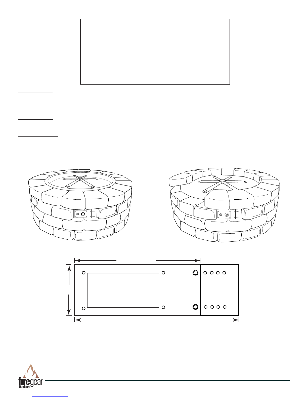
DESCRIPTION: The Paver Kit face plate bracket (control panel) is designed to install in conjunction with a typical Patio
Block re pit kit (purchased separately). It installs underneath the re pit pan or disc in place of one patio block. The
control panel itself provides a convenient location to house the gas valve and Piezo ignition (if applicable) then is easily
removed for servicing.
PRECAUTION: Ensure the PAVER-CP-TMSI control panel is within 40-inches of the 2-probe Piezo ignitor. This will allow
enough “play” in the wires to make your connections. See Fig. 9.
TOOLS NEEDED: (1) Drill/driver, Gas Rated Teon Tape or Compound, 5/16” Hex head driver, (1) 3/16” Concrete Drill
Bit, (2) Adjustable Wrenches, Assorted Open-end Wrenches
Fig. 1 Paver kit with re pit pan.
Fig 3. Paver Kit Control Panel Dimensions
Fig. 2. Paver kit with re pit at disc.
DIMENSIONS: The Paver Kit bracket and extension will t an opening with a maximum of 10½” wide x 3½” tall. Without
the Bracket Extension plate the maximum width is 8.00” wide. The holes in the Extension Bracket are spaced every ½”.
PAVER-CP-TMSI
REV. 8-24-18 Page 2

Paver Block
GENERAL INSTRUCTIONS
(U1-8C-S)
½" OD Flare x
⁄" MIP
Gas Inlet
Piezo Ignitor
NOTE: This section provide a general installation of
the Paver Kit Control Panel. See Table of Contents for
speci c instruction for your application. Follow the
directions from your paver block re pit kit to build the
actual re pit. Depending on your re pit pan ( at disc
or pan) ensure the Paver Kit control panel is installed
underneath the pan or disc.
Be sure the paver patio block kit ts the opening of the
re pit pan or disc before beginning your installation.
STEP 1: Determine the best location to install the paver
kit control panel per your installation.
STEP 2: Remove one block from your re pit enclosure
then measure the width between the opening.
Depending on the block width the control panel can be
adjusted to t various openings. NOTE: When
measuring it is recommended but not required to
recess the control panel to protect the valve
components from weather.
STEP 3: After you have determined the location and
measured the width to install the Paver Kit control panel
mark the inside of the control panel as shown in Fig. 4.
Place control panel into position, mark the
two holes, remove the control panel and
drill holes with 3/16” concrete drill bit.
LINTEL
Fig. 4 Securing the control panel into the paver block. Lintel
is shown in the gray shading.
STEP: 4 Drill the two holes with a 3/16” concrete drill
bit and secure the paver kit control panel with concrete
screws.
Use the linel to support the paver above control panel.
The lintel simply lays on top of the paver as shown in
Fig. 4.
TMSI VALVE INSTALLATON
Remove the TMSI valve and bracket assembly from the
plastic bag.
STEP 1: Prepare the re pit gas valve by installing a ⅜” close
nipple and ½” OD Flare x ⅜” brass tting that comes with the
PAVER-CP-TMSI kit into the gas inlet. Use gas rated Te on
tape or compound on the male threads. Ensure the ttings
are tight to prevent any gas leaks.
CAUTION: Do not use any Te on tape or compound on the
ared ends of the ttings.
Fig. 5 Control panel installed, ready for valve bracket.
PAVER-CP-TMSI
Fig. 6 Shows valve assembly removed from shipping bag.
REV. 8-24-18 Page 3

3/8” NPT
Close Nipple
3/8” NPT Black
Iron 90° Elbow
(U1-8C-S)
1/2" OD Flare x
3/8" MIP
Gas Inlet
Gas Oulet
Paver Block
Paver Block
From
Fire Pit
Inlet Gas
Supply
Piezo
Connections
STEP 2: Remove the ½” OD Flare x ⅜” brass tting installed in the inlet side of the gas valve and install the ⅜” close
nipple and black iron 90 degree elbow as shown in Fig. 7. Use gas rated Teon tape or compound on both male threads of
the nipple. Ensure the ttings are tight to prevent any gas leaks.
STEP 3: Clean off the male threads of the ½” OD Flare x ⅜” brass tting, Apply gas ratedTeon tape or compound to the
male threads and install it into the other end of the close nipple. See Fig. 7.
STEP 4: Install the main burner orice on burner pan of the
re pit. and secure the ex connector to the ½” ared tting.
See re pit manual.
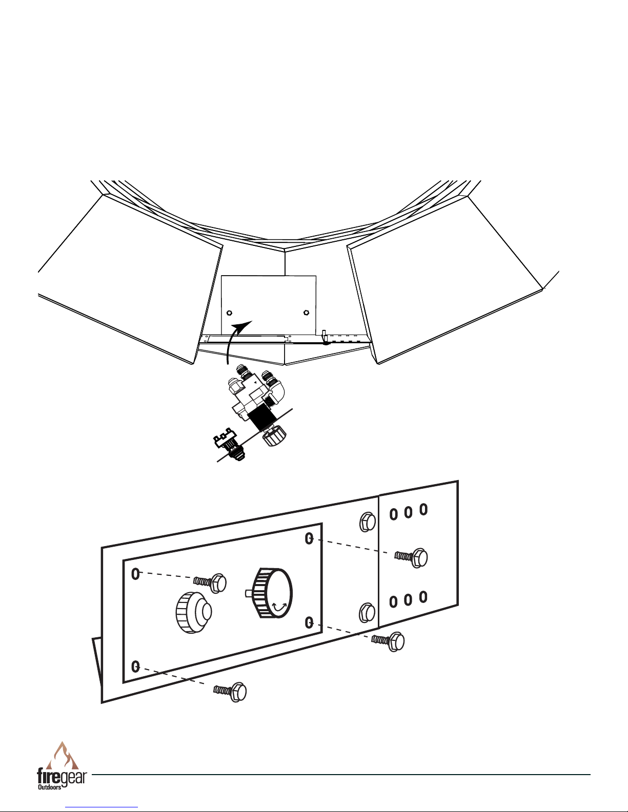
STEP 5: Temporarly set re pit into the enclosure to make
the following connections:
A. Install ex connector to main burner orice at bottom of
re pit then bring other end through the paver bracket.
B. Install ex connector to primary gas supply and feed the
other end through the paver bracket.
C. Feed the Piezo wires through paver bracket.
See Fig 8 for details.
STEP 6: Secure the ex connectors to the gas valve and
plug the Piezo wires into the back of the Piezo module.
Note: The Piezo wires are not polarity senstive therefore
they can plug into either connection of hte Piezo module.
Check for gas leaks before nal assembly.
Fig. 7. Installing ttings.
Fig. 8
Installing connections to valve bracket.
PAVER-CP-TMSI
REV. 8-24-18 Page 4
STEP 7: Once the ttings and wired are installed into the TMSI valve bracket then insert the valve bracket into Paver Kit
Paver Block
Paver Block
Bracket as shown in Fig. 9.
STEP 8: Secure the TMSI valve bracket into place using the (4) stainless thread cutting screws. See Fig. 10.
STEP 9: Conduct a trial burn test and check for any gas leaks before completing the installation. See install manual of
the re pit or page 7 for lighting instructions.
STEP 10: After burn test is complete, nish the patio paver block installation per the install manual.
Fig. 10 Close up view securing TMSI valve bracket to control panel.
Fig. 9 Installing TMSI valve into Paver Kit Bracket.
PAVER-CP-TMSI
REV. 8-24-18 Page 5

Lava Rock
Lava Rock
Lava Rock
Ignition Hood
Ignition Hood
Screen
TMS Valve
Gas Supply
Fire Pit Pan
Probe Assembly
Orange Wire
Piezo Module
PIEZO23WH
PIEZO48WH
Step 13: Test the ignitor by pushing and holding the red button to ensure the 2-probe ignitor is sparking inside the ignition
box in the burner pan. The spark should be located directly over top of the burner port hole for proper ignition of the gas
as previously discussed. Note: Fig. 11 show details of the PIEZO48WH wire connection if needed.
Fig. 11 Wiring diagram for complete system.
Step 14: Install the ignition hood screen. Ensure no media
covers hood. See Fig. 12. Install the lava rock/media
material according to re pit install manual then turn the
main gas supply back ON.
Installation is now complete.
CAUTION: ENSURE YOU HAVE LEAK TESTED THE FIRE PIT
BEFORE LIGHTING AND OPERATING.
Fig. 12 Installing mesh cover on the ignitor shield.
PAVER-CP-TMSI
REV. 8-24-18 Page 6
1
2
3
4
5
6
Drawings not to Scale
7
8
LIGHTING INSTRUCTIONS
READ ALL LIGHTING INSTRUCTIONS BEFORE ATTEMPTING TO LIGHT FIRE PIT
WARNING: Do not stand over re pit during ignition or operation due to high surface temperatures.
TURNING ON FIRE PIT
1. Push and hold the red button on the manual Piezo ignitor and ensure sparking is occurring at the probes inside re pit.
2. Rotate control knob on gas valve in the counter clockwise to ON position. See Fig. 13.
3. Depress control knob inward and push to light the burner.
4. Gas should ignite within 10 seconds or less. If re pit does not light within 10 seconds turn OFF the gas supply. Check
ignitor probe location, ensure there is an 1/8” gap between the probes with a good strong spark then repeat
steps 2 through 4.
5. Turn gas supply OFF and wait 5 minutes. Check probes and battery if re pit does not light.
6. Repeat steps 1-3.
TURNING OFF FIRE PIT
1. Slight push inward on control knob and turn clock wise until it stops. Fire pit
will turn OFF.
2. After cooling off install cover.
Fig. 13 TMSI control knob.
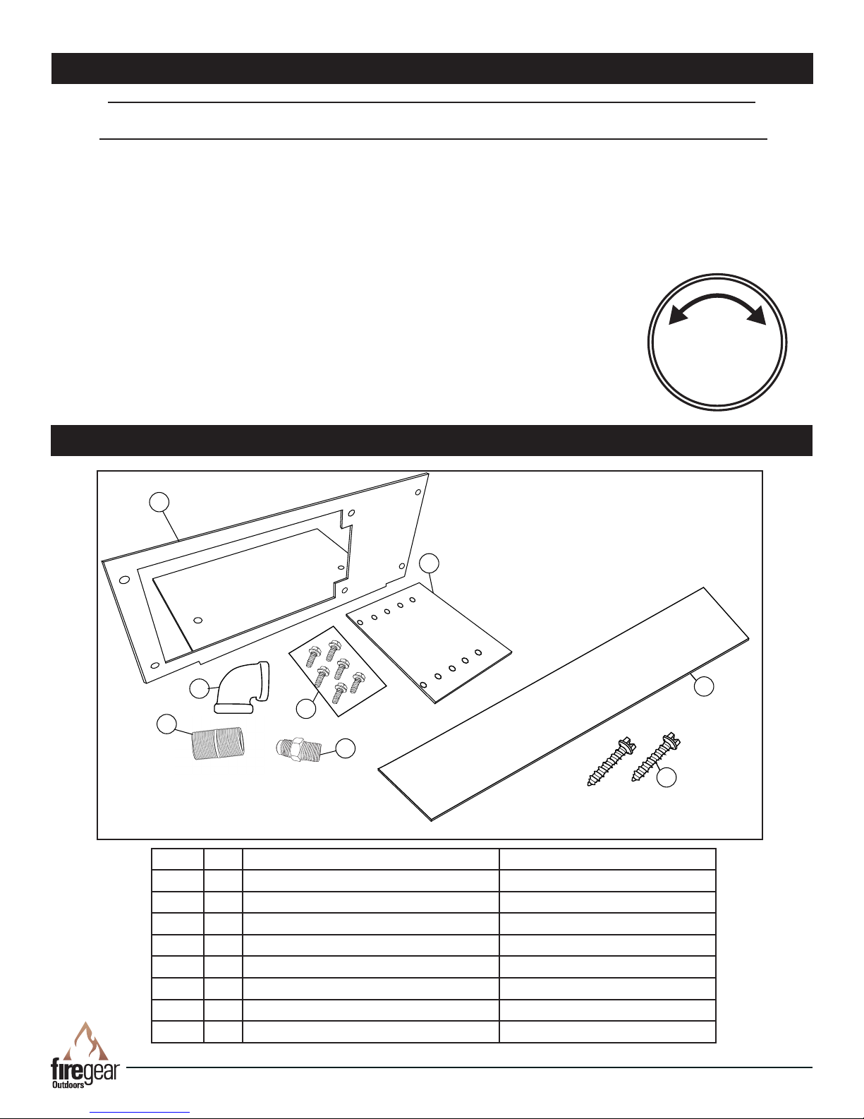
PAVER-CP-TMSI REPLACEMENT PARTS
ON
AT ON POSITION
SLIGHT PUSH TO
TURN OFF
FULL PUSH TO
OFF
LIGHT
Item # Qty. Description Part Number
1 1 Paver Kit Bracket PAVERKITBRACKET-SS
2 1 Paver Kit Bracket Extension PAVERKITBRACKETEXT-SS
3 6 ½” Stainless Thread Cutting Screw SCREW1024HXSS75
4 1 ⅜” NPT Black Iron 90° Elbow BS309-6
5 1 ⅜” NPT Male-Male Closed Nipple 113BS-C
6 1 ½” OD Flare x ⅜” MIP U1-8C-S
7 2 ¼” x 1¼” Concrete Screws SCREW.25MASONRY
8 1 3” X 12” Steel lintel PAVER-LINTEL
* Some part quantities will vary depending upon kit used.
PAVER-CP-TMSI
REV. 8-24-18 Page 7

LIMITED WARRANTY
Firegear Outdoors warrants the Paver Kit for 12 months from date of purchase or installation to original purchaser to be
free from defects in materials and workmanship. Damage to the Paver Kit caused by accident, misuse, abuse, or
installation error, whether performed by a contractor, service company, or owner, is not covered by this warranty.
Firegear Outdoors will not be responsible for labor charges and/or damage incurred in installation, repair, replacement, or
for incidental or consequential damage. Some states, provinces, and nations do not allow exclusion or limitations of
incidental or consequential damages, so the above limitations or exclusions may not apply. This warranty gives you
specic legal rights. You may also have other rights that vary by state, province, or nation.
FOR TECHNICAL SERVICE, CALL: (855) 498-8324
Tech Support E-mail: www.support@regearoutdoors.com
PAVER-CP-TMSI
Firegear Outdoors
9230 Conservation Way
Fort Wayne, IN 46809
Sales Support: (888) 699-6167
WEB SITE: www.regearoutdoors.com
REV. 8-24-18 Page 8
 Loading...