

Firegear OFP-72LECO-N, OFP-36LECO-NLED, OFP-48LECO-NLED, OFP-72LECO-NLED, OFP-60LECO-NLED Installation And Operating Instructions Manual
...
DO NOT DISCARD. THIS MANUAL
HAS IMPORTANT OPERATING AND
MANTENANCE INSTRUCTIONS.
LEAVE WITH THE HOMEOWNER.
MODEL:
SERIAL #:
Kalea Bay
Outdoor Gas Fireplace
Installation and Operating Instructions
MH# 60069
MODELS
Natural Gas Description
OFP-36LECO-N
OFP-48LECO-N
OFP-60LECO-N
OFP-72LECO-N
IF YOU CANNOT READ OR UNDERSTAND THESE INSTALLATION INSTRUCTIONS
DO NOT ATTEMPT TO INSTALL OR OPERATE THIS APPLIANCE
36” Open Front Fireplace
48” Open Front Fireplace
60” Open Front Fireplace
72” Open Front Fireplace
INSTALLATION PRECAUTION:
This replace requires a minimum 18-square inches (per side) of cross ventilation.
Failure to provide proper ventilation can void the warranty.
Warning: For Outdoor Use Only
CARBON MONOXIDE HAZZARD
DANGER
This appliance can produce carbon monoxide
which has no odor.
Using it in an enclosed area can kill you.
Never use this appliance in an enclosed space
such as a camper, tent, car or home.
DANGER
If you smell gas:
1. Shut off gas to the appliance.
2. Extinguish any open ame.
3. If odor continues, keep away from
the appliance and immediately call
your gas supplier or re department.
WARNING
Do not store or use gasoline or other
ammable vapors and liquids in the
vicinity of this or other appliances.
Any LP cylinder not connected for use
shall not be stored in the vicinity of this
or other appliances.
WARNING
Do not leave unattended during use.
Do not use for cooking.
Follow all gas leak procedures in this
manual prior to operation.
Improper installation, adjustment,
alteration, service or maintenance
can cause injury of property damage.
WARNING
Read the installation, operating and
maintenance instructions thoroughly
before installing or servicing this
equipment.
WARNING
If the information in these instructions is not followed exactly, a re or explosion
may result causing property damage, personal injury or death.
FOR YOUR SAFETY
Do not store or use gasoline or other ammable vapors and liquids in the vicinity
of this or other appliance.
Kalea Bay Outdoor Fireplace
REV. 4-17-19 Page 2

CALIFORNIA PROPOSITION 65
WARNING
This product is designed to operate with one of the following fuel sources: Liquid Propane or Natural Gas.
The fuel used to operate this product, and the products of combustion of such fuel, can expose you to
chemicals including Benzene which is known to the State of California to cause cancer, birth defects and
other reproductive harm and Carbon Monoxide which is known to the State of California to cause birth
defects or other reproductive harm.
(For more information go to: www.p65Warnings.ca.gov.)
CERTIFICATION: These outdoor replaces are tested and
approved to ANSI Z21.97-2014, CSA 2.41-2014
standards by Underwriters Laboratories using listing
MH#60069. It should be installed by a qualied installer in
accordance with local and state building codes using
National Fuel Gas Code ANSI Z223.1/NFPA54 or current
CSA-B149.1 installation codes for Gas Burning Appliances
and Equipment in Canada.
DESCRIPTION: These Outdoor replace models come
ready to operate with HI/LO capabilities once installation is
complete.
These are radiant replaces only and do not have a fan
option. Do not burn real wood or other combustible
materials in these replaces. Use only approved media.
All models are shipped as Natural Gas but can be
converted to Propane Gas by ordering an optional
conversion kit. See page 29.
There is no top or rear venting required for this replace,
however, it is mandatory to provide adequate clearances
according to this manual and cross ventilation in the
enclosure.
SAFETY
1. This appliance is congured from the factory only as
Natural gas. It appliance can be converted to LP gas.
2. Do not place Propane (LP) supply tanks inside any
unapproved structures. Locate propane tanks outdoors
if unsure.
3. This replace is to be used only outdoors in a well
ventilated space and shall not be used in a building,
garage, or any other enclosed area.
4. Do not use this replace as a wood burning replace.
Use only high temperature media approved for use with
this replace.
5. Do not use this replace to cook or burn paper or other
objects.
6. Do not use if exposed to or under water. Immediately
call a qualied service technician to inspect the
replace and replace any part of the control system
and any gas control which has been under water.
7. Turn replace OFF and let cool before servicing. Only
a qualied service person should perform service.
The burner assembly is removable for service. NEVER
obstruct the front opening(s) of the replace.
CAUTION:
All media (i.e. lava rock, lava stones, lava boulders and
re glass) have the potential of thermal spalling. This is a
process that may occur when media is wet and moisture
gets trapped inside of the material due to rapid temperature
differences. When this happens the media has the
potential to crack or “pop” outside the replace. Heavy
rains, high humidity and the presence of moisture can
contribute to this process.
LOCAL CODES
Install and use replace with care. Follow all local codes.
In the absence of local codes, use the latest edition of the
National Fuel Gas Code ANSI Z223.1/ NFPA54.
Available from:
American National Standards Institute, Inc.
25 West 43rd Street, 4th oor
New York, NY 10036
National Fire Protection Association, Inc.
1 Batterymarch Park
Quincy, MA 02169-7471
ALWAYS USE CAUTION WHEN USING THE FIREPLACE
Extra caution should be taken when lighting a replace
when heavy rains, high humidity and moisture are present.
Light the replace and leave the area while the heat
dissipates any moisture out of the media. We strongly
recommend that during this drying out time that you monitor
the replace from a distance. This drying out period should
be no less than 30 minutes. Continue monitoring the ame
from a safe distance to ensure that all popping has ceased
before fully enjoying the re.
Kalea Bay Outdoor Fireplace
REV. 4-17-19 Page 3
Fuels used in gas red appliances, and the products of combustion such as fuels, contain
chemicals known to cause cancer, birth defects and/or other reproductive harm.
This warning is issued pursuant to the California Health & Safety Code Sec. 25249.1
IT IS IMPORTANT TO READ THROUGH THE ENTIRE INSTALLATION MANUAL
BEFORE BEGINNING INSTALLATION OF THIS FIREPLACE!!
TABLE OF CONTENTS
Certication, Description & Safety Information 3
Installation Precautions 5-7
Gas Line & Cross Ventilation Requirements 6-7
Hard Piping & High Elevation 7
Fireplace Specications 8
Gas Pipe Sizing 9
Single-Sided Fireplace Application 10
Dimensions; Combustible Clearances; Mantel Clearances 11
Framing with Metal Studs 12
See-Through Fireplace Application 13-15
Dimensions; Combustible Clearances; Mantel Clearances 14
Framing with Metal Studs 15
Final Preparation
Wiring to Control Box 16
Control Box Installation 17-18
Wiring Diagrams 19-20
Installing Pilot Covers in Burner Pan 21
Installation of Media in Burner Pan/Trough & Pilot Operation 22-23
Installation of Hoods and Windshield 23-24
Glass Holder Installation and Windshield 24-25
Flame Height 25
Programming Optional Remote Controls 25
Operation
Operating & Lighting Instructions 26
Replacement Parts 27
Replacement Parts List 28
Gas Conversion (Natural Gas to LP Gas) 29-31
Fireplace Maintenance 32
Troubleshooting 33-34
Optional Accessories 35
Warranty 36
This replace ships from the factory as a single-sided replace.
An optional kit must be purchased to convert it into a see-through replace.
If you choose to install it as a see-through, ensure you use pages 12 & 13 for proper
specications. Carefully read through this manual to understand.
Kalea Bay Outdoor Fireplace
REV. 4-17-19 Page 4

INSTALLATION PRECAUTIONS
1. These replaces are designed for outdoor use only. Not approved for any indoor use.
2. We recommend using ¾” black iron pipe; however please refer to the NFPA54 (National Fuel Gas Code) for proper
pipe sizing when exceeding 20-feet in length for replaces .
3. Determine which replace you are preparing to install, single-sided or see-through. (Refer to page 9 or 12).
4. This replace is not a “load bearing” replace. All nishing materials must be supported by the surrounding
structure and not rely on the replace itself.
5. Follow the local code requirements for the gas type being used. This replace should be installed in accordance with
local codes and ordinances or in the absence of local codes, with the latest National Fuel Gas Code, ANSI Z223.1
NFPA54 or CSA B149.1, Natural and Propane Installation Code in Canada.
6. Fireplaces create high temperatures, it is very important to have any combustibles at a safe distance.
7. Fireplace should never be left unattended while in operation. It should always be a safe distance from all trees and
combustible landscape materials.
8. The replace must be installed on a at, level, stable, non-combustible surface. Exception: It is permissible
to place one layer of ½” cement board underneath the entire replace, then it may sit on a at, level, stable,
combustible surface. Drainage is critical to ensure that water does not damage gas valve and components.
Never install the replace below grade.
9. CAUTION: A minimum of 18 square inches of cross ventilation (per side) is required to keep the inside of the
enclosure dry. Install the supplied VENT-KIT-6x12SS approximately 3 to 4 inches from the oor centered on each end
of the replace (See Fig. 3, page 6).
10. Never ll the cavity under and around the valve box with any material, this is air space necessary for ventilation.
11. Only non-combustible materials (i.e. metal studs and cement board) should come in direct contact with any part
of the replace. Underneath area should be non-combustible or a at level combustible surface according to the
clearances specied in this manual. Bend out nailing anges on ends of replace and secure to metal studs.
12. Hearth Extension: A hearth extension is not required with this replace. Any hearth extension used is for
appearance only and does not have to conform to a standard hearth extension installation requirements.
13. This replace is designed to have glass media covering the burner trough, so the burner tube is not visible.
Media is NOT provided and must be purchased seperately. When installing media use minimum of ½” to ¾”
diameter Firegear Outdoors glass to ll the burner trough. After the burner trough is covered you are permitted to ll
the remaining area in the burner pan. DO NOT COVER THE IGNITION HOOD WITH ANY ROCK OR MEDIA. See
Figs. 33 & 34 on pages 25 and 26 for details.
14. Gas lines and ttings must be installed into the non-combustible structure. All gas connections must be leak tested
before installation of the replace. Leak detection is required before regular use of the replace.
15. Do not use media that will absorb moisture over time and will not release this moisture quickly. Moisture can boil in
this media and can rapidly break apart and cause property damage or personal injury.
16. Never leave any other combustible material on top of the replace. This could cause unsafe operation of this system
and damage to the component that will not be covered under our warranty.
17. It is recommended to wear gloves when moving the replace into position and watch for sharp edges when handling
the replace.
Kalea Bay Outdoor Fireplace
REV. 4-17-19 Page 5

INSTALLATION PRECAUTIONS
B
u
r
ner
Fireplace Side Wall
Remove Screws
B
u
r
n
er
p
a
n
B
o
t
t
o
m
E
n
d
Gas Shut-o
CAUTION: BEFORE BEGINNING INSTALLATION CAREFULLY REMOVE THE
GLASS WINDSHIELD, PARTS BOX AND ANY PACKING MATERIALS FROM
FIREPLACE AND SET ASIDE FOR LATER USE.
FRAMING: After framing is complete, place the replace into position and secure it with the side nailing anges. Next
install cement board, securing it to the metal studs and replace. The framing provides for a ush t up to the opening of
the replace. DO NOT PROTRUDE INTO THE FIREPLACE OPENING WITH CEMENT BOARD.
GAS LINE: The gas line must have a predetermined location to enable it to be installed. Fig. 1 shows one example of an
inlet gas line with a gas shut off at the replace. This allows a technician to shut the inlet gas supply OFF and remove the
burner for servicing. Ensure you follow the local and state gas codes per your installation.
RECOMMENDATION: Once the gas line is established it is recommended to remove the burner pan from the rebox
until the replace is in the nal stages and ready for the burner installation. See burner pan removal below in Fig. 2.
GAS CONVERSION: The burner pan must be removed from the replace to convert it to LP gas. See pages 29-31.
Fig.1 Close up view of inlet gas connection with
shut-off valve.
IMPORTANT: It is permissible to reverse the burner pan in
the eld to enable a closer gas line connection if necessary.
BURNER PAN REMOVAL
Step 1: Lift out the pilot cover on each end of the burner.
Step 2: Remove the three (3) screws in the bottom end.
Then lift the bottom end up and out from both sides of the
burner pan area.
Step 3: Remove the four (4) screws (two on each end) out
from the burner pan. They are located at the outer edge of
the burner pan, on each corner (See Fig. 2).
VENTILATION FOR NON-COMBUSTIBLE ENCLOSURE
Fireplaces are subjected to many outdoor elements such as
rain, snow, wind, heat or cold. A minimum of 18 square
inches of cross ventilation (2 sides) is required to keep
the components in good working order. Use Fig. 3 as a
guide.
Kalea Bay Outdoor Fireplace
Fig. 2 Removal of burner pan screws.
Fig 3. Cross ventilation example providing minimum of 18-square
inches per side using Firegear VENT-KIT-6x12SS provided.
REV. 4-17-19 Page 6
INSTALLATION PRECAUTIONS
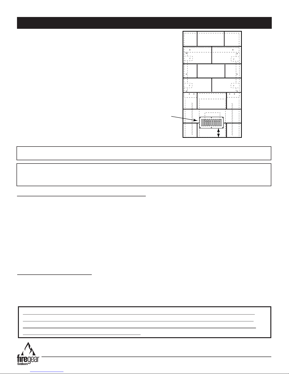
3-4”
Vent
The vents (VENT-KIT-6x12 ) used for cross ventilation should
be installed at each end of the replace. Vents should be
placed 3-4” from the bottom of the replace and centered side
to side as shown in Fig. 3B.
Fig. 3B Vent location.
WARNING: Proper clearances from combustible, construction materials must be maintained from all sides, top and
bottom of this appliance.
IMPORTANT
Installation of Natural or Liquid Propane Gas should be done by a qualied installer, service agency or gas supplier.
This appliance must be isolated from the gas supply piping system by closing its manual shutoff valve during any
pressure testing of the gas supply piping system at test pressures equal to or less than ½ “psig (3.5kPa)
HARD PIPING TO FIREPLACE WITHOUT GAS PROXIMITY
NOTE: We recommend using ¾” black iron pipe; however please refer to the NFPA54 (National Fuel Gas Code) for
proper pipe sizing when exceeding 20-feet in length for replaces rated above 100,000 BTU.
1. Turn OFF gas supply system. NOTE: All gas connections (except for brass to brass) require the following: Clean
pipe threads using either a wire brush or steel wool. Apply pipe sealant to the ttings before making any connection.
BE CAREFUL! Ensure all gas connections are snug, but do not over tighten!
2. Extend the gas supply using minimum of ¾” black iron pipe or an approved exible gas line from existing house
supply. This can be accomplished by teeing off or tapping into a gas line connection. Install necessary pipe for the
distance required and then install a manual shut-off valve at the exterior house wall. If pipe is to pass through a
foundation or house wall, make sure to re-seal the area around the pipe with weather sealant.
3. The primary gas shut-off (supplied) will require a ½” male ared tting to enable connection of the stainless steel ex
gas line supplied with the replace (See Fig. 1 page 6).
HIGH ELEVATION INSTALLATION
This appliance is listed for elevations from 0 to 4500 feet in Canada and the U.S. If elevation exceeds 4500 feet it may
be necessary to decrease the input rating by changing the existing burner orice to a smaller size. Input should be
reduced 4% for each 1000 feet beyond the 4500 feet above sea level. Check with your local gas utility for assistance in
determining the proper orice in your location. In some cases the heating value may already be reduced and downsizing
the orice may not be necessary.
PAY CLOSE ATTENTION TO THE FOLLOWING PAGES. THIS FIREPLACE IS SHIPPED AS A
SINGLE-SIDED FIREPLACE, HOWEVER YOU HAVE THE OPTION TO CONVERT IT INTO A
SEE-THROUGH FIREPLACE WITH AN OPTIONAL KIT. SEE-THROUGH DIMENSIONS AND
CLEARANCES ARE LISTED ON PAGE 12 & 13.
Kalea Bay Outdoor Fireplace
REV. 4-17-19 Page 7
SPECIFICATIONS
NOTE: These replaces come shipped as Natural Gas models only. There is an LP conversion kit available as an
accessory. Ensure you order the specic conversion kit for your model replace. Table 1 shows the applicable information
if converting to Liquid Propane (LP) gas. See page 29.
IMPORTANT: It is permissible to reverse the burner pan in the eld to enable a closer gas line connection if necessary.
FRAMING FIREPLACE
NG
NG Models:
OFP-36LECO-N #41 31,000 18,500 #44 OFP-36LECO-LPK OAS-LP52 ECO-LSS-52
OFP-48LECO-N #32 43,500 24,500 #34 OFP-48LECO-LPK OAS-LP48 ECO-LSS-46
OFP-60LECO-N #30 50,000 36,000 #27 OFP-60LECO-LPK OAS-LP44 ECO-LSS-42
OFP-72LECO-N #25 65,000 42,000 #18 OFP-72LECO-LPK OAS-LP42 ECO-LSS-35
Table 1. Fireplace specications and conversion kits.
Factory
Orice
NG
Btu’s
High
Disclaimer: Btu listings are based on 7.0”WC for Natural Gas at inlet side
of gas regulator. Flex line sizing and proper gas pipe sizing can affect Btu’s.
As a result, your Btu’s may vary slightly from Table 1 specications.
NG
Btu’s
Low
NG Low
Rate
Screw
LP
Conversion Kit
LP Factory
Orice
LP Low Rate
Screw
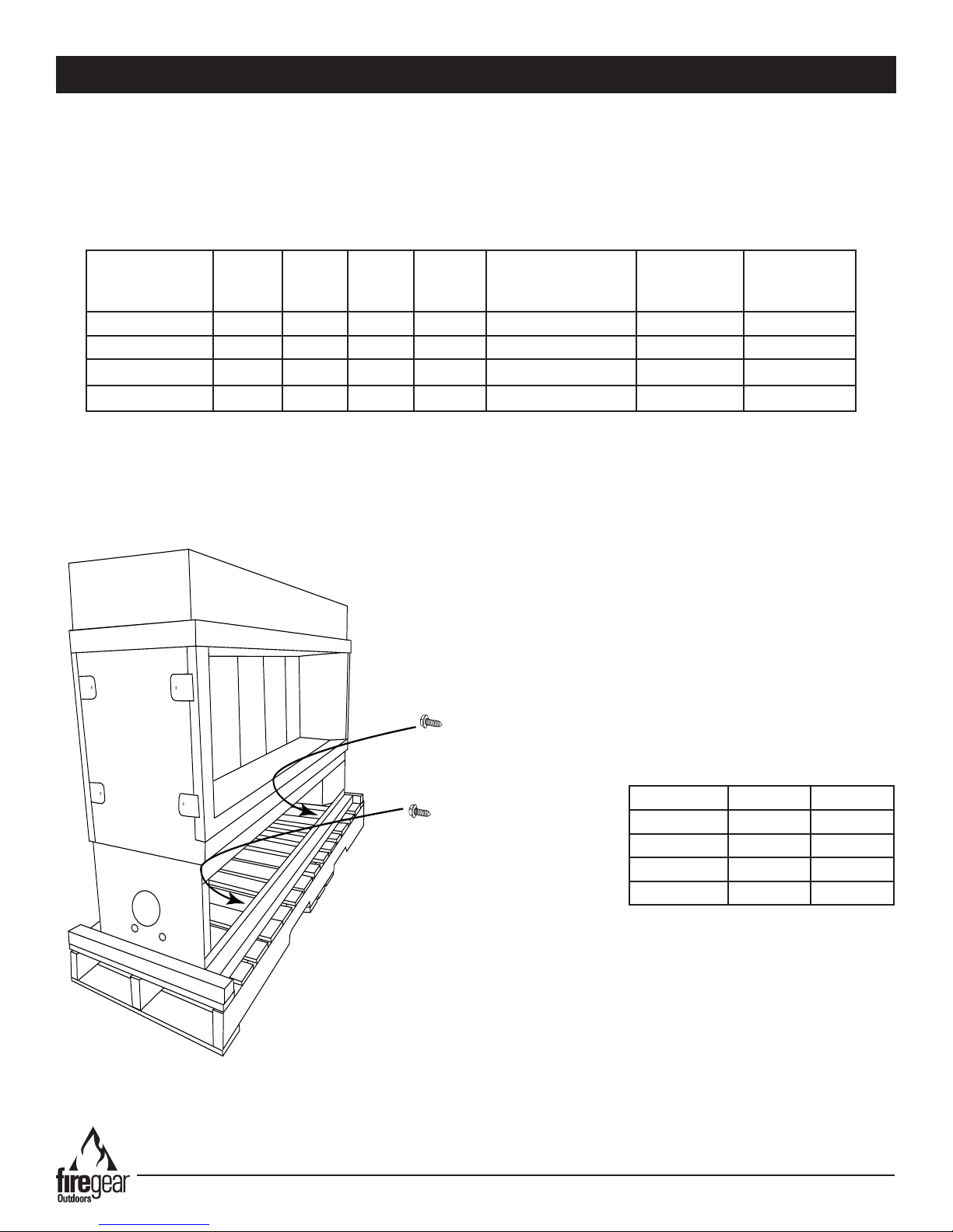
Fig. 4 The replace ships on a wooden skid. Remove the
screws as shown and lift replace off of skid.
Note: Number of screws vary with model size.
Kalea Bay Outdoor Fireplace
Pressure NG LP
Min. Inlet 5.0” WC 10.5” WC
Max. Inlet 10.5” WC 13.0” WC
Normal Inlet 7.0” WC 11.0” WC
Manifold 4.0”WC 10.0”WC
Table 2 Gas Pressures
REV. 4-17-19 Page 8

REFERENCE
GAS PIPE SIZING
Length of Pipe in Feet
1/2” 3/4” 1” 1 - 1/4” 1 - 1/2” 2” 2 - 2 1/2” 3” 4”
10 275 567 1071 2205 3307 6221 10140 17990 35710
20 189 393 732 1496 2299 4331 7046 12510 25520
30 152 315 590 1212 1858 3465 5695 10110 20620
40 129 267 504 1039 1559 2992 4778 8481 17300
50 114 237 448 913 1417 2646 4343 7708 15730
60 103 217 409 834 1275 2394 3908 6936 14150
70 89 185 346 724 1086 2047 3329 5908 12050
80 78 162 307 630 976 1811 2991 5309 10830
90 69 146 275 567 866 1606 2654 4711 9613
100 63 132 252 511 787 1496 2412 4281 8736
125 54 11 2 209 439 665 1282 2083 3618 7382
150 48 100 185 390 590 1138 1808 3210 6549
175 43 90 168 353 534 1030 1637 2905 5927
200 40 83 155 325 491 947 1505 2671 5450
300 37 77 144 303 458 887 1404 2492 5084
NATURAL GAS : PIPE SIZING CHART
•
Natural Gas (NG) flow is given in
thousands of BTU/hr. = 1 cubic
foot of NG gas - 1000 BTU
•
Nominal pressure at the burner
for Natural Gas is 3.5” of water
column. (Typical machine supply
5”-7”)
•
Pipe length must include
additional length for all fittings.
Add approximately 5 feet of pipe
per fitting.
•
Natural Gas Example: A machine
with a burner that requires
440,000 BTU would need a 1 -1/4”
pipe for a 20” long run.
LIQUID PROPANE : PIPE SIZING CHART
NOTE: The sizing charts above list the specific pipe sizes required for the amount of BTU’s for a new gas line installations. If you
are using an existing gas line you must take into consideration the existing gas line capacities to ensure you will have proper
pressure. This chart is for reference only, we recommend you consult with a Licensed Plumber/Gas Fitter or NFPA54 (National Fuel
Gas Code - current edition) for more details.
Length of Pipe in Feet 1/2” 3/4” 1” 1 - 1/4” 1 - 1/2” 2” 2 - 2 1/2” 3” 4”
10 108 230 387 793 1237 2259 3640 6434 -
20 75 160 280 569 877 1610 2613 5236 9521
30 61 129 224 471 719 1335 2165 4107 7859
40 52 11 0 196 401 635 1143 1867 3258 6795
50 46 98 177 364 560 1041 1680 2936 6142
60 42 89 159 336 513 957 1559 2684 5647
70 38 82 149 317 476 896 1447 2492 5250
80 36 76 140 239 443 840 1353 2315 4900
90 33 71 133 275 420 793 1288 2203 4667
100 32 68 126 266 411 775 1246 2128 4518
125 28 60 11 7 243 369 700 1143 1904 4065
150 25 54 105 215 327 625 1008 1689 3645
175 23 50 93 196 303 583 993 1554 3370
200 22 47 84 182 280 541 877 1437 3160
300 17 37 70 145 224 439 686 1139 2539
•
Liquid Propane (LP) Gas flow is
given in thousands of BTU/hr. =
1 cubic foot of LP gas - 2500 BTU.
•
This chart refers to low pressure LP,
after regulation, Standard nominal
pressure at the burner for Liquid
Propane Gas is 11” of water column.
•
Pipe length must include additional
length for all fittings. Add
approximately 5 feet of pipe per
fitting.
•
LP Example: A machine with a
burner that requires 440,000 BTU
would need a 1” pipe for a 20’ long
run.
GAS PIPE SIZING
Table 3 Gas pipe sizing chart
Kalea Bay Outdoor Fireplace
REV. 4-17-19 Page 9

SINGLE-SIDED FIREPLACE
DIMENSIONS, FRAMING
AND CLEARANCES SECTION
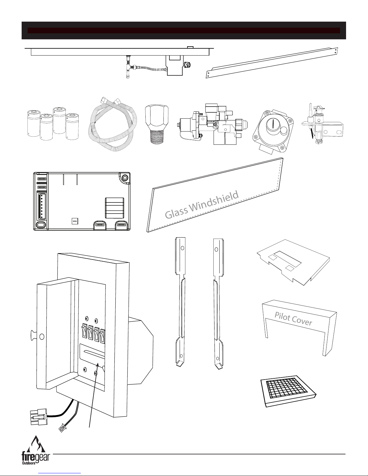
This replace comes with two boxes prepackaged inside and
outside the replace. Do not discard any boxes unless noted
to do so. Read the list below for the contents.
PART NUMBER DESCRIPTION QTY.
77140 Parts box (includes all parts in box) 1
VENT-6X12SS 6x12 vent kit (includes 2- stainless vents;
12- washers, 12- nuts; 12- screws & manual)
01-487 01-487 connector valve ½” 1
ST3-100-1027 Wire screen mesh 1
77116 10-foot Module Wire Harness 1
76207 Pilot cover 2
77139 FG Control Box Assembly 1
VCS-ECOBBUEXT120 120” extension wire harness for battery pack 1
BATTC C-size batteries 4
1
(36”) 73230 (48”) 74230
(60”) 75230 (72”) 76230
76119 Glass Holder - Right 1
76124 Glass Holder - Left 1
77129 8-32x ½” Phillips pan screw SS 11
(36”) 73131 (48”) 74131
(60”) 75131 (72”) 76131
(36”) KB-36-73120
(48”) KB-36-73120
(60”) KB-60-73120
(72”) KB-72-73120
Windshileld parts box (includes all items listed
below)
Hood 1
Windshield (see part # for specic sizes) 1
1
The bottom support n seen in several gure drawings on pages 11 to 14 has pre-punched holes on inside edge to
secure the replace into position before attaching cement board.
Kalea Bay Outdoor Fireplace
REV. 4-17-19 Page 10
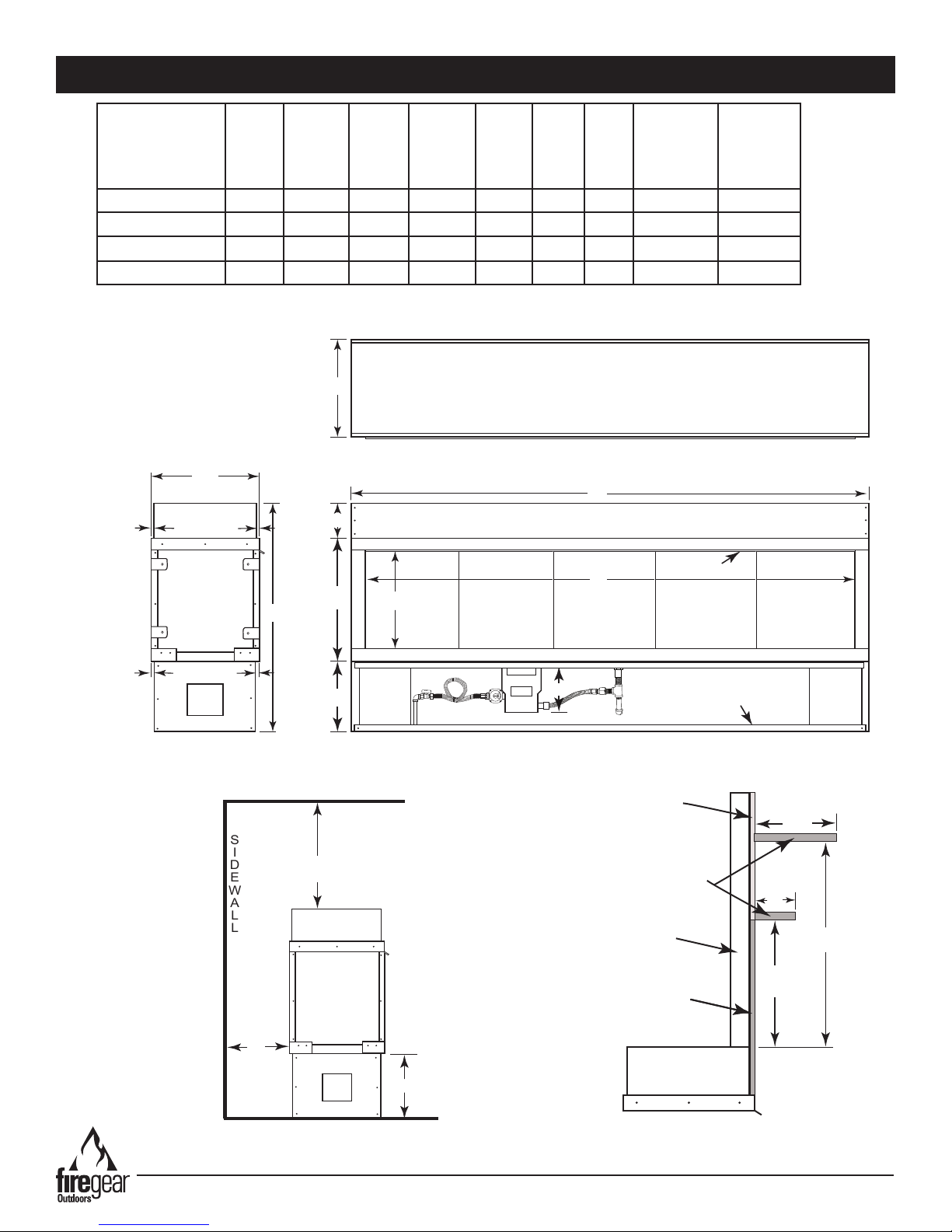
SINGLE-SIDED FIREPLACE DIMENSIONS & CLEARANCES
FRONT VIEW
TOP VIEW
END VIEW
E
E
C
6”
20”
F
D
A
B
G
Bottom Finish Fin
Hood
½”
½”
(Typ. Each Side)
(Typ. Each Side)
I
H
END VIEW
SIDEWALL
CEILING
FLOOR
11½”
Back
Front
Model:
Natural Gas (NG)
OFP-36LECO-N
OFP-48LECO-N
OFP-60LECO-N
OFP-72LECO-N
A
Overall
Length
40” 36” 37½” 16” 16¼” 11½” 8¾” 6” 42 ½”
52” 48” 37½” 16” 16¼” 11½” 8¾” 6” 42 ½”
64” 60” 37½” 16” 16¼” 11½” 8¾” 6” 42 ½”
76” 72” 37½” 16” 16¼” 11½” 8¾” 6” 42 ½”
B
Inside
Opening
C
Overall
Height
D
Opening
Height
E
Overall
Depth
F
Leg
Height
G
Valve
Box
Depth
H
Clearance
To
Combustible
Side Wall
Clearance
Combustible
Ceiling
I
To
Table 4 Fireplace dimensions and clearances. Ensure you follow the proper clearances during installation.
Fig. 5 Fireplace dimensions; refer to Table 3.
Fig. 6 Single-sided replace clearance to
Kalea Bay Outdoor Fireplace
combustibles (See Table 3)
Combustible
Material Permitted
12”
Combustible
Shelf
Metal Studs
Non-Combustible
6”
18”
12”
Facing Material
TOP OF
FIREPLACE
END VIEW
Fig. 7 Open front replace mantel clearances
REV. 4-17-19 Page 11

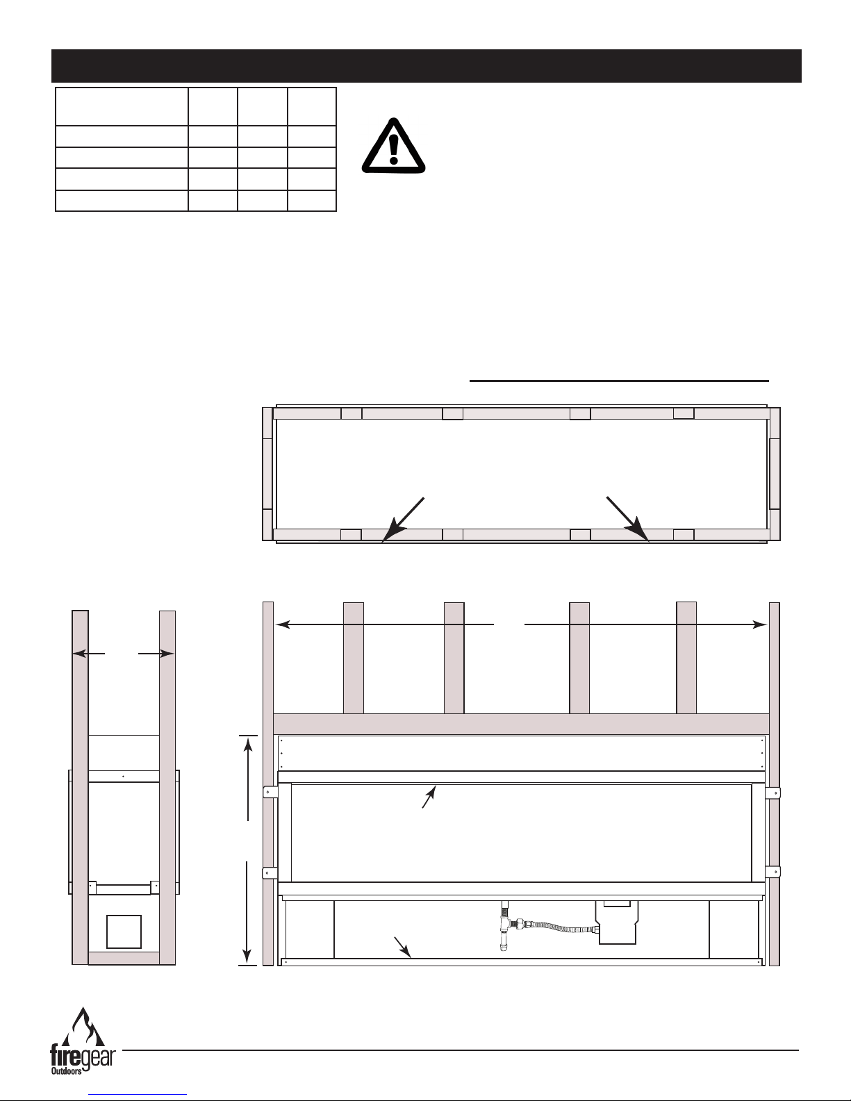
SINGLE-SIDED FRAMING DIMENSIONS WITH METAL STUDS
Model:
Natural Gas (NG)
OFP-36LECO-N
OFP-48LECO-N
OFP-60LECO-N
OFP-72LECO-N
Table 5 Fireplace framing dimensions.
A
Width
40 ½” 37 ¾” 15¾”
52 ½” 37¾” 15¾”
64 ½” 37 ¾” 15¾”
76 ½” 37 ¾” 15¾”
B
HeightCDepth
NOTE: This outdoor replace is not a “load bearing”
replace. All nishing materials must be supported
by the surrounding structure and not rely on the
replace itself.
NOTE: This replace requires metal studs for framing. WOOD STUDS ARE NOT PERMITTED.
C
Metal Studs
(Front)
A
Metal Studs Metal Studs
Metal Studs
Hood
*Metal studs shown in gray.
B
Bottom Support Fin
Fig. 8 Framing dimensions using all non-combustible materials for single-sided replace; refer to Table 4.
Kalea Bay Outdoor Fireplace
REV. 4-17-19 Page 12

SEE-THROUGH FIREPLACE
DIMENSIONS, FRAMING
AND CLEARANCES SECTION
Kalea Bay Outdoor Fireplace
REV. 4-17-19 Page 13

END VIEW
12”
18” TYP.
TOP OF
FIREPLACE
6”
12”
Non-combustible
facing material
Combustible
Material Permit-
Metal
Studs
6”
12”
Combustible Shelf
Combustible Shelf
SEE-THROUGH FIREPLACE DIMENSIONS & CLEARANCES ONLY
I
H
END VIEW
SIDEWALL
CEILING
FLOOR
11½”
Back
Front
FRONT VIEW
TOP VIEW
END VIEW
E
E
C
6”
20”
F
D
A
B
G
Bottom Finish Fin
Hood
½”
½”
(Typ. Each Side)
(Typ. Each Side)
This replace ships from the factory as a single sided replace, but by removing the back panels you can convert it
into a see-through replace. Your specic application, single sided verses see-through, will determine your installation.
Ensure you follow the proper clearances during installation.
Model:
Natural Gas
(NG)
OFP-36LECO-N
OFP-48LECO-N
OFP-60LECO-N
OFP-72LECO-N
A
Overall
Length
40” 36” 37½” 16” 16” 11½” 8¾” 36” 42 ½”
52” 48” 37½” 16” 16” 11½” 8¾” 36” 42 ½”
64” 60” 37½” 16” 16” 11½” 8¾” 36” 42 ½”
76” 72” 37½” 16” 16” 11½” 8¾” 36” 42 ½”
B
Inside
Opening
C
Overall
Height
Table 6 Fireplace dimensions and clearances.
D
Opening
Height
E
Overall
Depth
F
Leg
Height
G
Valve
Box
Depth
H
Clearance
To
Combustible
Side Wall
I
Clearance
To
Combustible
Ceiling
Fig. 10 Fireplace dimensions; refer to Table 6
Fig. 11 See-through replace clearance to
combustibles (See Table 6)
Kalea Bay Outdoor Fireplace
Fig. 12 See-through replace mantel clearances
REV. 4-17-19 Page 14
SEE-THROUGH FRAMING DIMENSIONS WITH METAL STUDS
A
B
Metal Studs Metal Studs
*
Metal studs shown in gray.
Bottom Support Fin
Hood
C
Metal Studs
Metal Studs
Top view showing ½” lip using
non-combustible facing material at front face
Model:
Natural Gas (NG)
OFP-36LECO-N
OFP-48LECO-N
OFP-60LECO-N
OFP-72LECO-N
Table 7 Fireplace framing dimensions.
A
Width
40 ½” 37 ¾” 15”
52 ½” 37¾” 15”
64 ½” 37 ¾” 15”
76 ½” 37 ¾” 15”
B
HeightCDepth
NOTE: This outdoor replace is not a “load bearing”
replace. All nishing materials must be supported
by the surrounding structure and not rely on the
replace itself.
NOTE: This replace requires metal studs for framing. WOOD STUDS ARE NOT PERMITTED.
Fig. 13 Framing dimensions using all non-combustible materials for see-through replace; refer to Table 7.
Kalea Bay Outdoor Fireplace
REV. 4-17-19 Page 15

# 77115
# 77113
ON/OFF
LOW
HIGH
LEARN
CONT.
PILOT
Battery Drawer
# VCS-ECOBBUEXT32
# VCS-ECOBBUEXT32
# VCS-ECOBBUEXT120
WIRING TO CONTROL BOX
Kalea Bay Outdoor Fireplace
Fig. 14 Overview of replace wiring to control box. Note: The replace is provided with 10-feet of wire. If you require a longer length, an
optional 10-foot wire harness 77116 & VCS-ECOBBUEXT120 are available in replaemet parts section.
REV. 4-17-19 Page 16

CONTROL BOX INSTALLATION
Cover Plate Surrounding Switch
Remove screws to mount switch plate
Remove screws to mount switch plate
ON/OFF
LOW
HIGH
LEARN
CONT.
PILOT
Battery Drawer
Nylon Latch
5 /”
5 /”
Mounting plate under switch cover
ON/OFF
LOW
HIGH
LEARN
CONT.
PILOT
Battery Drawer
Step 1: After the replace has been framed into position begin determining the control box location. Locate the module
wire harness (#77115) and battery pack harness (#VCS-ECOBBUEXT32) protruding outside of the valve box. Refer to
page 16 Fig. 14.
Step 2: Connect the module wire harness #77115 to #77113 wire harness (10’ wire harness from parts box).
Step 3: Connect the #VCS-ECOBBUEXT32 to the other #VCS-ECOBBUEXT120 (10’ battery pack wire harness from
parts box).
Fig. 15 Control box with 8 ¾” x 8 ¾” cover/face plate.
Step 4: Remove the control box from the components parts carton. The replace is supplied with 10-feet of wiring for the
control box switch installation. Find a suitable location within a close proximity of the replace for convenience of operation
and mount the control box upright and level as shown in Fig. 14 on page 16. Use Figs 15 & 16 for dimensional reference.
CAUTION: Ensure all switches are in the OFF position. “I” indicates ignite/ON and “O” indicates OFF. The switch on the
far right is a “Learn” switch. It does not turn ON and OFF, it remains in its original position.
Step 5: Remove the four (4) outer screws from each corner inside the cover plate shown in Fig. 15 and remove the outer
face plate and nylon latch. This will expose the mounting plate. See Fig. 16. CAUTION: Do not remove the two center
screws from the cover plate. This will release the entire switch box wiring from inside the junction box and make it difcult
to reinstall.
Step 6: Install the control box mounting plate into framing members/nish material and secure into place. Replace the
mounting plate ush with wall materials or allow for depth of wall material to slide under the four corners of the plate. The
mounting plate will then be ush with the wall.
Kalea Bay Outdoor Fireplace
Fig. 16 Control box mounting plate
REV. 4-17-19 Page 17
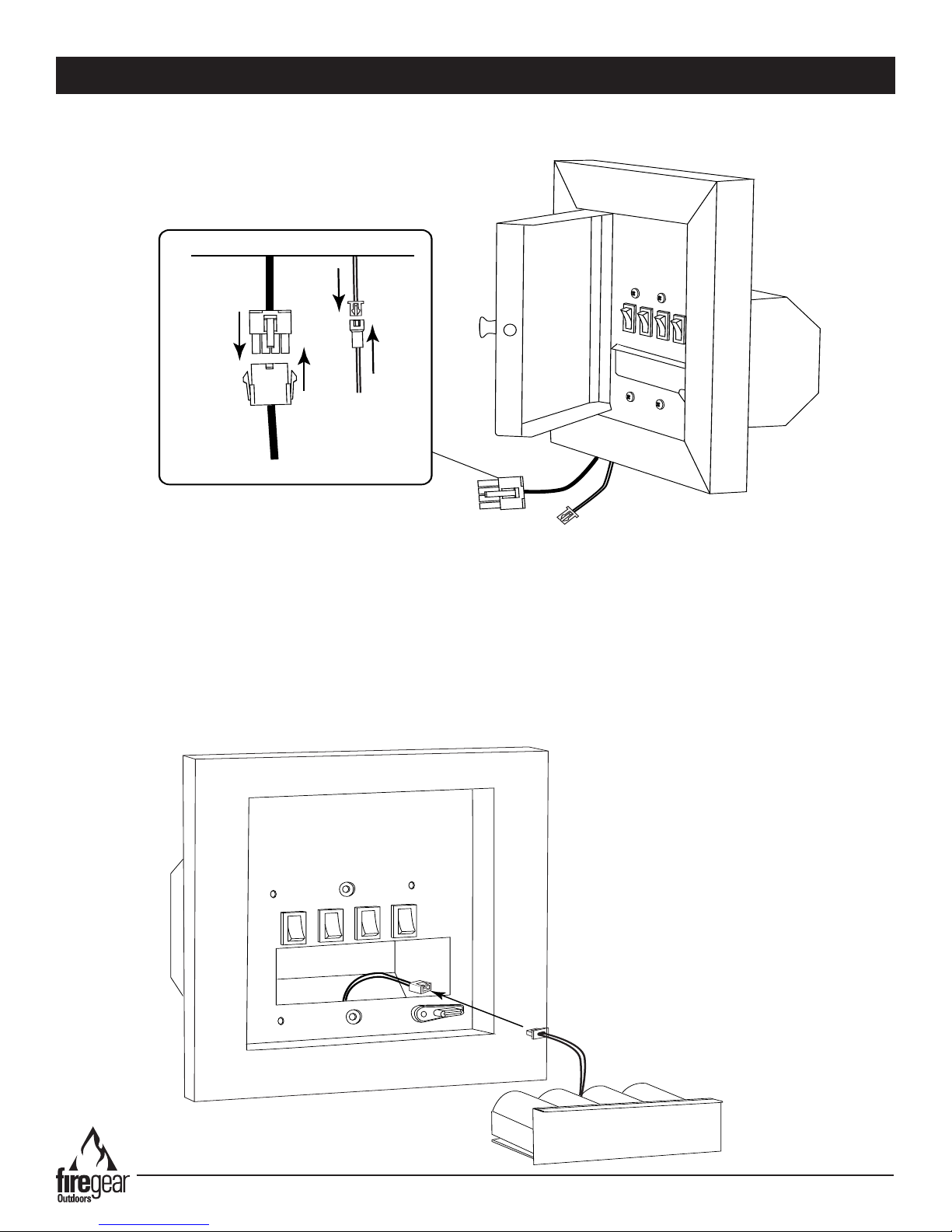
Connect the
2-PIN connector
CONTROL BOX INSTALLATION
Battery Wire
Connection
Molex Wire
Connection
Control Box
Wire Connection Detail
Step 7: Feed the wire harrness (# 77113) up to the control box and attach the Molex connectors from the module wire
harness to the control box wire harness. At the same time, connect the 2-PIN connector (#VCS-ECOBBUEXT32) from
module wire harness to the 2-PIN connector inside the control box. See Fig. 17. Refer to page 16 Fig. 14.
Fig. 17 Wire connection detail
Step 8: Reinstall the control box cover/face plate and nylon latch back on the control box mounting plate.
Step 9: Turn (rotate) the nylon latch up or down (out of the way) of the battery box drawer (Fig. 16; page 17).
Step 10: Pull the battery box drawer out of the control box and install the (4) C-size batteries (included) in the battery
pack. Follow the diagram inside for battery direction.
Step 11: Look for the 2-PIN connector at the back of the battery pack and the mating 2-PIN connector inside the control
box. Insert the male connetor into the female connector then carefully install the battery pack drawer back into the control
box. Move the nylon latch over edge of the battery box drawer to secure it into place. See Fig. 18. Note: Careful not to
pinch the wires when installing the battery box drawer back into the control box.
Fig. 18 Battery pack wire connection
Kalea Bay Outdoor Fireplace
REV. 4-17-19 Page 18

#77114
#77116
#77115
LEARN
ON/OFF
HI/LOW
IPI/
CONT
PILOT
VCS-ECOMOD
(Inside valve box)
REPRESENTS COMPONENTS INSIDE
CONTROL BOX
REPRESENTS COMPONENTS
INSIDE FIREPLACE
Brown
Blue
Yellow
Black
C Battery
C Battery
C Battery
C Battery
VCS-BBUC Battery Pack
VCS-ECOBBUEXT32
VCS-ECOBBUEXT32
VCS-ECOBBUEXT120
MODULE & BATTERY PACK WIRING
Kalea Bay Outdoor Fireplace
Fig. 19 This wiring diagram shows wiring from control panel and battery pack to control module. Each is independent of the other.
REV. 4-17-19 Page 19

VALVE SAFETY WIRE
(V-Wire)
VCS-ECOMOD
(Control Module)
1/2 PSI
SPAIN
INLET
OUTLET
PILOT TUBE
S
I
SWITCHES
POWER
MOTOR COMM.
BATT
V
BRONZE INSULATED WIRE
BLACK WIRE
BRASS WIRE
(GROUND)
MOTOR DRIVE WIRES
SWITCHES MOUNTED
IN CONTROL BOX
LOW RATE
SET SCREW
C Battery
C Battery
C Battery
C Battery
WIRING DIAGRAM INSIDE VALVE BOX
Kalea Bay Outdoor Fireplace
Fig. 20 This wiring diagram shows the components inside the valve box. The dotted line box shows the components external of the valve box.
REV. 4-17-19 Page 20

FINAL PREPARATION
B
u
r
ner
Fireplace Side Wall
Pilot Cover
Fireplace Side Wall
P
i
l
o
t
C
o
v
e
r
B
u
r
ner
B
u
r
n
e
r
E
n
d
When the replace is framed into position and the gas line is run in place it is recommended to burn test the replace
before the nish work is complete. This will ensure proper operation and enables the installer to check for any gas leaks
at the replace.
NOTE: The pilot covers have a plastic lm that must be removed before installing.
Once the burner pan assembly is secured into position, the pilot covers must be installed (one on each side). After you
have removed the plastic lm install the pilot covers into the open slot of each burner end (spacers that center the burner)
with the open side of pilot cover facing toward the replace side wall (See Figures 21-22). NOTE: Even though there is
no pilot on the opposite end the other pilot cover provides combustion air evenly to the burner for
operation.
REMOVE PLASTIC FILM
FROM PILOT COVER
No media allowed
in shaded area
Fig. 21 Installing pilot cover.
No media allowed
in shaded area
Fig. 22 Pilot cover installed.
Kalea Bay Outdoor Fireplace
REV. 4-17-19 Page 21

FINAL PREPARATION
Burner
Trough
½” - ¾”
Crushed Glass
BURNER PAN ASSEMBLY
Pilot
(Hidden Underneath)
Burner
Tube
Ignition
Hole
FINAL PREPARATION
PILOT OPERATION & TEST FIRE
The pilot assembly is located at the end of the burner
hidden underneath a pilot cover. Ensure the pilot ame
is passing through the ignition hole in the burner pan for
proper ignition. Use the Fig. 23 as a guide.
Test re the replace before installing media. At the same
time this is a good time to double check for any gas leaks
or electrical connections before nalizing the installation by
installing the glass media.
Fig. 23 Proper pilot ame through ignition hole.
Fig. 24 Installing media into the replace.
INSTALLING MEDIA
Open the media box and install the glass media as shown
is Figs. 24 & 25. Place media reglass into the trough area
rst as shown in Fig. 24. Use the remaining media to ll
the burner pan equally on both sides. After lling the trough
reinstall the mesh hood overtop of the pilot area.
Keep media in burner pan the same level as the trough to
allow the burner area to appear as one complete
burner pan.
IMPORTANT: Media can only be placed in the trough and
burner pan area. No media is to be place into the shaded
area shown in Fig. 26 on page 22.
CAUTION: Ensure there is no media in the ignition hole
area. The burner tube gas ignites in this area to light the
replace. Media in this area could cause delayed ignition.
The replace requires ½”-¾” large broken reglass to be
installed into the burner trough and burner pan. Use the
table below to assist in determining the amount of media
needed for your specic model.
Large Broken Glass
Model # Burner pan & Trough
36”
48”
60”
72”
Table 8 Media specications. Requires ½” - ¾”
reglass (Burner pan media amount does not include
the trough)
15lbs.
20lbs.
25lbs.
25lbs.
Kalea Bay Outdoor Fireplace
REV. 4-17-19 Page 22

FINAL PREPARATION
Burner Pan End View Showing Media Placement
Proper Media Height
Burner Tube
Hood Screw Locations
FRONT VIEW
SIDE VIEW
Hood
(Deector Facing Downward)
Hood Detail
End View
Fig. 25 End view of burner with media.
Note: Media amounts listed in Table 8 are guides and can
vary depending on media used. Ensure not to cover more
than ½ -inch above the actual burner tube and keep all
media within the burner pan area (See Figs. 24, 25, & 26).
No Media in
Shaded Areas
No Media on
Mesh Screen Cover
Large Broken Glass in
Burner Trough and
Burnerpan
Fig. 26 Covering the entire replace oor is NOT permitted
in the shaded area.
INSTALLING HOOD(S)
The replace requires a hood to be installed into the upper opening of the rebox. All models require ve (5) screws to
secure the hood to the replace except the 72-inch model, which uses seven (7) screws to secure the hood. The hood
protrudes 1-inch from replace opening. Fig. 27 shows hole location and installation process for hood installation. The
protruding area of the hood is to be angled downward for proper installation, see Hood Detail below.
Fig. 27 Installing hood(s) on the replace.
Kalea Bay Outdoor Fireplace
REV. 4-17-19 Page 23

FINAL PREPARATION
Fireplace Inner
Side Panel
These
rivet-nuts
not used.
7”
CAUTION
HOT SURFACE
DO NOT TOUCH
GLASS WINDSHIELD
Glass Holders
Fig. 28 Windshield glass holder location.
GLASS HOLDER INSTALLATION
The glass windshield(s) slide into the two clips on each
end of the replace and rest in position if installing for the
replace (See Fig. 29) for the location. Use two screws
(#77129) for each glass holder. Insert screws into the
installed in the replace side wall to secure the glass
holders. There is one glass windshield provided with this
replace. The glass will rest on the bottom tab of each
windshield clip.
CAUTION: THIS IS TEMPERED GLASS. DO NOT CHIP
GLASS. CHIPPED TEMPERED GLASS CAN BREAK
WITHOUT WARNING.
WARNING: During operation of the replace the
glass will get hot! Hot glass can cause burns.
DO NOT TOUCH glass until cooled.
NEVER allow children to touch the glass.
Kalea Bay Outdoor Fireplace
Fig. 29 Installing windshield into clips (glass holders).
REV. 4-17-19 Page 24

FINAL PREPARATION
1
2
GLASS WINDSHIELD
GLASS WINDSHIELD
Side View
Installing Glass
Side View of
Installed Glass
Bottom Tab Bottom Tab
ON/OFF
LOW
HIGH
LEARN
CONT.
PILOT
WINDSHIELD INSTALLATION
The glass windshield(s) slide into the glass holders on each
end of the replace and rest in position if installing for the
replace (See Fig.30) for the location. Use two screws
(#77129) for each glass holder. Insert screws into the
installed in the replace side wall to secure the glass
holders. There is one glass windshield provided with this
replace. The glass will rest on the bottom tab of each
windshield glass holder.
CAUTION: THIS IS TEMPERED GLASS. DO NOT CHIP
GLASS. CHIPPED TEMPERED GLASS CAN BREAK
WITHOUT WARNING.
FLAME HEIGHT
Fig. 30 Proper ame height.
Proper ame height (Fig. 31) should be at the top edge of glass windshield (peaking above at times) while on HI setting.
Note: Glass windshield is 7-inches tall. The LO setting will be at least half of the height of HI or maybe lower. There can
be a variance in ame height between Natural Gas and Liquid Propane (LP) Gas models.
Fig. 31 Proper ame height.
PROGRAMMING OPTIONAL REMOTE CONTROLS
LEARNING TRANSMITTER TO MODULE
1. To LEARN (pair) the remote transmitter to the control module, press and release the LEARN button (switch) in the
control box. See Fig. 32. You will hear single audible beep indicating the module is ready to learn the transmitter
Fig. 32 Control panel
security code. Press any button on the transmitter within 60 seconds. The code is accepted when you hear 4 short
beeps in rapid succession. Security codes will be retained in memory indenitely if power is removed. Note: Control
module accepts a total of three (3) wireless transmitters.
2. To Clear Codes: Press and hold learn switch on for 6-seconds to clear all transmitter security codes retained in
memory. Codes are clear when you hear three long beeps in succession.
Note: After “Learning” the remote control to the control module you will be able to operate the replace with the
remote, without pushing any of the switches inside the control box. You still have the option to operate the replace
manually if needed by accessing the control box and pushing the ON/OFF switch. Refer to the lighting instructions above.
Kalea Bay Outdoor Fireplace
REV. 4-17-19 Page 25
OPERATION
ON/OFF
LOW
HIGH
LEARN
CONT.
PILOT
CAUTION: Children and adults should be alerted to the hazards on high surface temperatures and should stay away to
avoid burns or clothing ignition. Young children should be carefully supervised when they are in the area of the appliance.
WARNING: Do not use this appliance if any part has been under water. Immediately call a qualied service technician
to inspect the appliance and to replace any part of control system and any gas control, that has been under water.
SAFETY WARNINGS
1. Never leave the replace unattended during operation.
2. Clothing or other ammable materials should not be placed on or near the appliance.
3. Any guard or other protective device removed for servicing the appliance must be replaced prior to operating the
appliance.
4. Installation and repair should be done by a qualied service person. The appliance should be inspected before
use and at least annually by a qualied service person. More frequent cleaning may be required as necessary. It
is imperative the control compartment, burners and circulating air passageways of the appliance be kept clean.
5. Inspect the fuel supply connection before each use of the appliance.
6. Temporary storage of this appliance indoors is permissible only if it has been disconnected from its fuel supply
(Natural or L.P. gas line).
WARNING
1. This appliance is hot when operated and can cause severe burns if contacted.
2. Do not burn any solid fuels in this appliance.
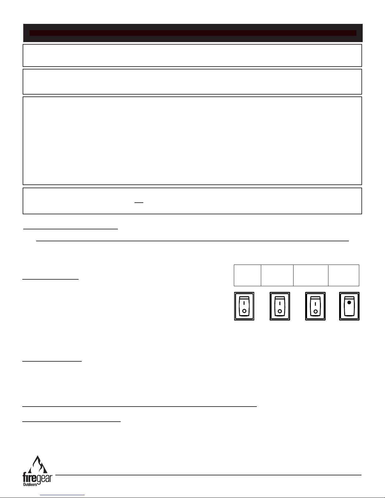
LIGHTING INSTRUCTIONS
READ ALL WARNING AND SAFETY INFORMATION ABOVE BEFORE ATTEMPTING TO LIGHT FIREPLACE
Turn ON main gas supply and check all ttings and connections for leaks with a soap and water solution.
HOW TO TURN ON
1. Push the “I” on the ON/OFF switch to turn ON. System will take
approximately 7-10 seconds before ignition after the gas line is
purged. See Fig. 33. The main ame ignites (defaults) in the HIGH
position. Press the “I” on the LOW/HIGH button to adjust to the LOW
ame setting, if desired.
2. If re pit does not light after second try, turn main gas OFF, wait 5
minutes and repeat steps 1.
Note: A continuous pilot ame can be turned ON or OFF using the continuous pilot switch.
HOW TO TURN OFF
1. To turn OFF the replace press the “O” position on the ON/OFF switch. This will turn OFF the replace.
NOTE: Fireplace must turned OFF for 5-minutes before relighting.
LEARN BUTTON: IS ONLY USED WHEN PROGRAMMING REMOTE CONTROLS
Fig. 33 Control panel
REMOTE CONTROL OPERATION
If using a remote control, the rocker switches in the control panel will not be used. Depending on the remote control,
simply press the ON button to operate the replace. See bottom of page 24 for reference.
Kalea Bay Outdoor Fireplace
REV. 4-17-19 Page 26
G
l
a
s
s
W
i
n
d
shi
e
l
d
1
S
I
SWITCHES
POWER
MOTOR COMM.
BAT T
V
P
i
l
o
t
C
o
v
e
r
1/2 PSI
SPAIN
C Size Battery
C Size Battery
C Size Battery
C Size Battery
REPLACEMENT PARTS
2
3
9
4
5
10
6
Drawings Not to Scale
7
8
15
12
11
Kalea Bay Outdoor Fireplace
13
14
17
* Not all parts are shown but all are listed
on replacement parts page.
16
REV. 4-17-19 Page 27

REPLACEMENT PARTS LIST
Item
1 Complete Stainless Steel Burner Pan Assembly 36”-(73229) 48”-(74229) 60”-(75229) 72”-(76229)
2 Bottom Support Fin - 2 per unit 36”-(73130) 48”-(74130) 60”-(75130) 72”-(76130)
3 C-Size Batteries (requires (4); supplied with replace) BATTC
4 1/2” Flex Gas Line (46-inch Length) T-200-9898-46
5 Air Shutter Orice NG (for 36” Natural Gas Models) OAS-NG41
5 Air Shutter Orice NG (for 48” Natural Gas Models) OAS-NG32
5 Air Shutter Orice NG (for 60” Natural Gas Models) OAS-NG30
5 Air Shutter Orice NG (for 72” Natural Gas Models) OAS-NG25
6 EcoFlow Gas Valve with Step Motor with ECO-LSS-44 for 36” Model 73224
6 EcoFlow Gas Valve with Step Motor with ECO-LSS-34 for 48” Mode 73224
6 EcoFlow Gas Valve with Step Motor with ECO-LSS-27 for 60” Model 74224
6 EcoFlow Gas Valve with Step Motor with ECO-LSS-44 for 72” Model 75224
7 Natural Gas Regulator (convertible to LP) See page 33 REG-C80K-NG
8 Side Mount Pilot Assembly (complete assembly with TC) ECO-VK-PILOT
9 Ignition Control Module ( includes 8-pin wire harness) ECO-VK-ECOMOD-WWH
10 Tempered Glass Windshield for 36” model (¼” x 8” x 35 ½”) (Pkg of 1) KB-36-73120
10 Tempered Glass Windshield for 48” model (¼” x 8” x 47 ½”) (Pkg of 1) KB-48-74120
10 Tempered Glass Windshield for 60” model (¼” x 8” x 59 ½”) (Pkg of 1) KB-60-75120
10 Tempered Glass Windshield for 72” model (¼” x 8” x 71 ½”) (Pkg of 1) KB-72-76120
11 Battery pack drawer assembly (uses 4 C size batteries) 77141
12 FG Control Box Assembly 77139
13 Glass Holder -Right 304SS (1 pc stainless) 76119
14 Glass Holder - Left 304SS (1 pc stainless) 76124
15 Bottom End (Used to center burner pan into replace) 76125
16 Pilot Cover (Sits inside bottom end, item #18) 76207
17 Mesh Screen Cover (Ignition Hood) ST3-100-1027
18 120” wire harness extension for battery pack (VCS-ECOBBUC) - not shown VCS-ECOBBUEXT120
19 Manual gas shut-off valve ½” OD Fare x ½” FIP -not shown 01-487
20 Fireplace Hood - (deects heat from top opening) not shown 36”-(73131) 48”-(74131) 60”-(75131) 72”-(76131)
21 Poly Lightng Label - not shown 77144
22 10-foot Module Wire Harness- not shown 77116
23 8-32 x ½” Pan head screw - stainless steel - not shown 77129
Description
Part Number
Note: All items are shipped as one replacement part unless noted in the description.
Kalea Bay Outdoor Fireplace
REV. 4-17-19 Page 28
NG
Regulator
Plastic Stem
Regulator
Aluminum
Cap
Valve Box
Disconnect
Flex Line
Orice
Regulator
Pilot Box
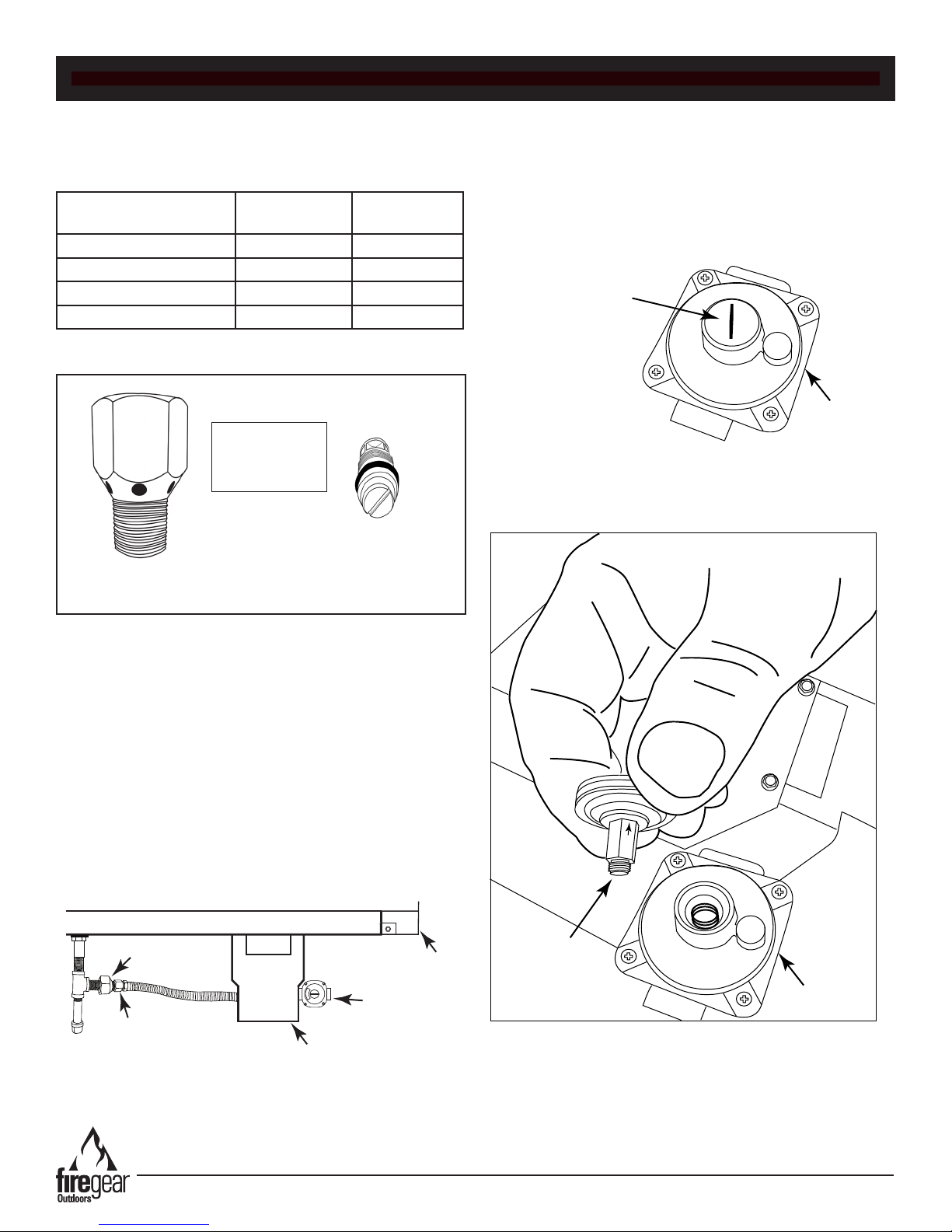
NATURAL GAS TO LP GAS CONVERSION
This kit will properly convert the outdoor replace to LP gas. Kit contents are: (1) OAS-LP# (Brass orice) and (1) ECOLSS# (Brass low rate set screw), (1) LP Conversion label (placed next to blank space on rating label, (1) Installation
instruction
Model Main Burner
Orice
OFP-36LECO-LPK OAS-LP52 ECO-LSS-52
OFP-48LECO-LPK OAS-LP48 ECO-LSS-46
OFP-60LECO-LPK OAS-LP44 ECO-LSS-42
OFP-72LECO-LPK OAS-LP42 ECO-LSS-35
Table 1 Reference information
This replace was
converted to LP gas by
__________________
Date: ______________
Low Rate Set
Screw
Label
Low Rate Set
Main Burner Orice
(OAS-LP#)
Fig. 1. Contents of kit
Screw
(ECO-LSS-#)
Step 4: Locate the gas regulator on the opposite side of
the valve box. Using a regular size at bladed screwdriver
remove the aluminum cap and washer from the regulator.
See Fig. 2.
Fig. 3 Regulator
cap location
Step 5: On the underneath side of the aluminum cap is a
plastic stem. Using a 6mm wrench remove the stem,
unscrew the stem (counter-clockwise), turn it over and
install the opposite end back into the cap. See Fig. 4.
Step 1: Turn OFF the gas supply to the outdoor
replace and disconnect any electrical power.
Step 2: Remove the burner pan from the replace to
enable conversion access. See installation manual if
necessary.
Step 3. Disconnect the ex line at the main burner
orice. Then remove the orice and ared tting from the
orice. Re-tape the ared tting with the new OAS-LP
orice per Table 1. Ensure to use gas rated Teon tape
around the threads or pipe compound. Check for leaks
after conversion is complete.
Fig. 2 Changing main burner orice
Kalea Bay Outdoor Fireplace
Fig. 4 Regulator stem shown in NG setting
NOTE: The plastic stem has a marking on it with an arrow.
Look carefully on the stem, it may be difcult to read.
The gas type is determined with the arrow pointing at the
aluminum cap as seen in Figs. 4 and 5.
REV. 4-17-19 Page 29
Regulator
Plastic Stem
LP
M
e
t
a
l
Pi
l
o
t
B
o
x
Bu
rner Pan
Pilot Hood
Removable Clip
Vent Hole
(partially blocked
by brass orice)
NATURAL GAS TO LP GAS CONVERSION
Fig. 5 Regulator stem shown in LP setting
CAUTION: Ensure the aluminum cap is installed with the
plastic stem seated completely into the cap and the metal
washer is installed with the aluminum cap.
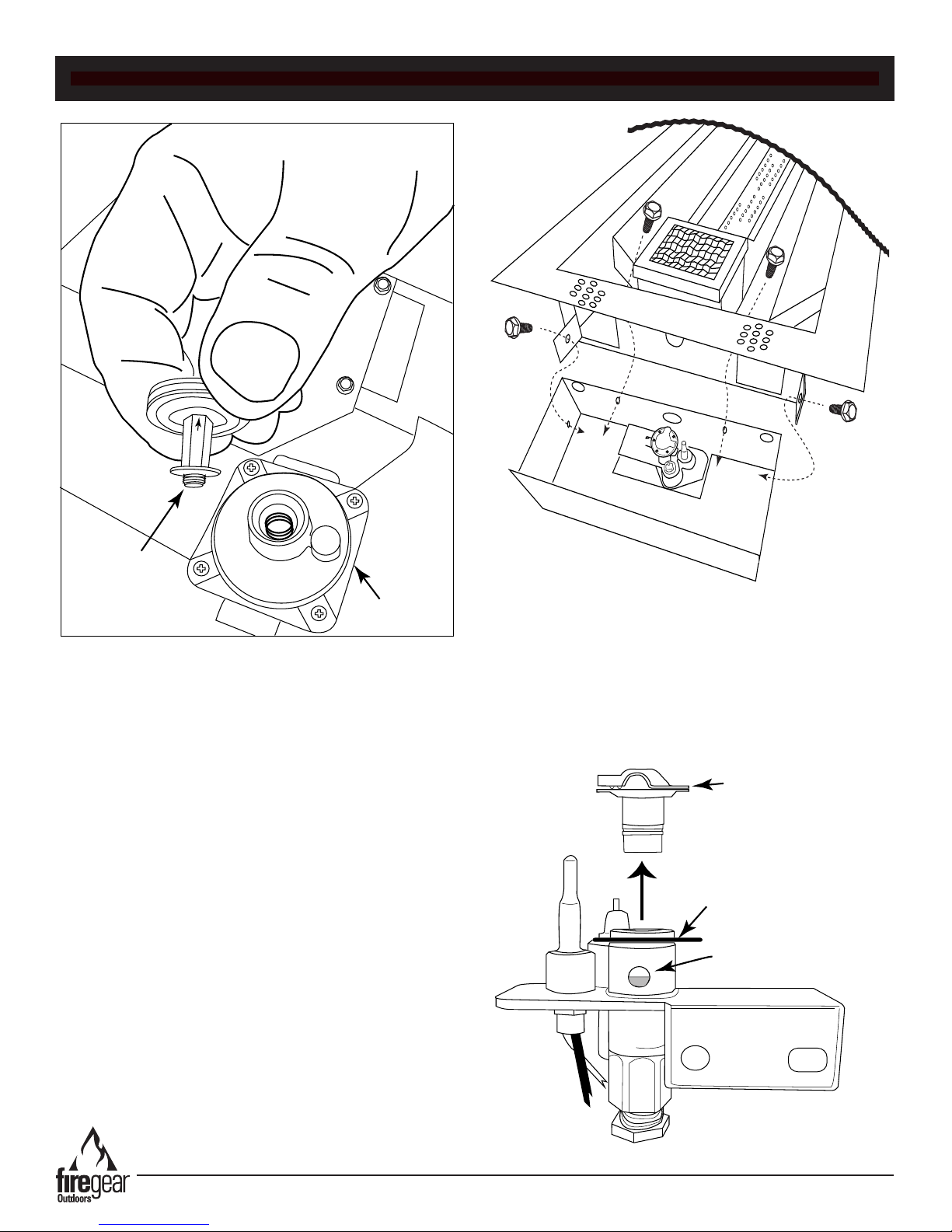
Step 6: Secure the aluminum cap with a screwdriver.
Step 7: On the end of the burner pan where the pilot is
located (See Fig. 6), remove the four (4) 1/14” hex head
screws securing the metal pilot box. Two screws are
located inside the burner pan, one on each side of the
ignitor box screen mesh hood and the other two are
securing a metal tab on each side of the pilot box. See Fig.
6 for screw locations.
Fig. 6 Pilot box screw locations
Step 8: Once the pilot box is loose and exposes the pilot
assembly then proceed to removing the pilot hood.
The pilot hood should lift straight up and out of the pilot
assembly. If not, remove the wire clip with a small
screwdriver or needle-nose pliers, then lift up. See Fig. 9.
Kalea Bay Outdoor Fireplace
Fig. 7 Pilot hood removal
REV. 4-17-19 Page 30
Top View of
Pilot Assembly
Vent Hole
(mostly open after
converting to LP)
Valve Box
Low Rate
Set Screw
Burner Pan Side View
Low Rate
Set Screw
Pressure Tap
Pressure Tap
NATURAL GAS TO LP GAS CONVERSION
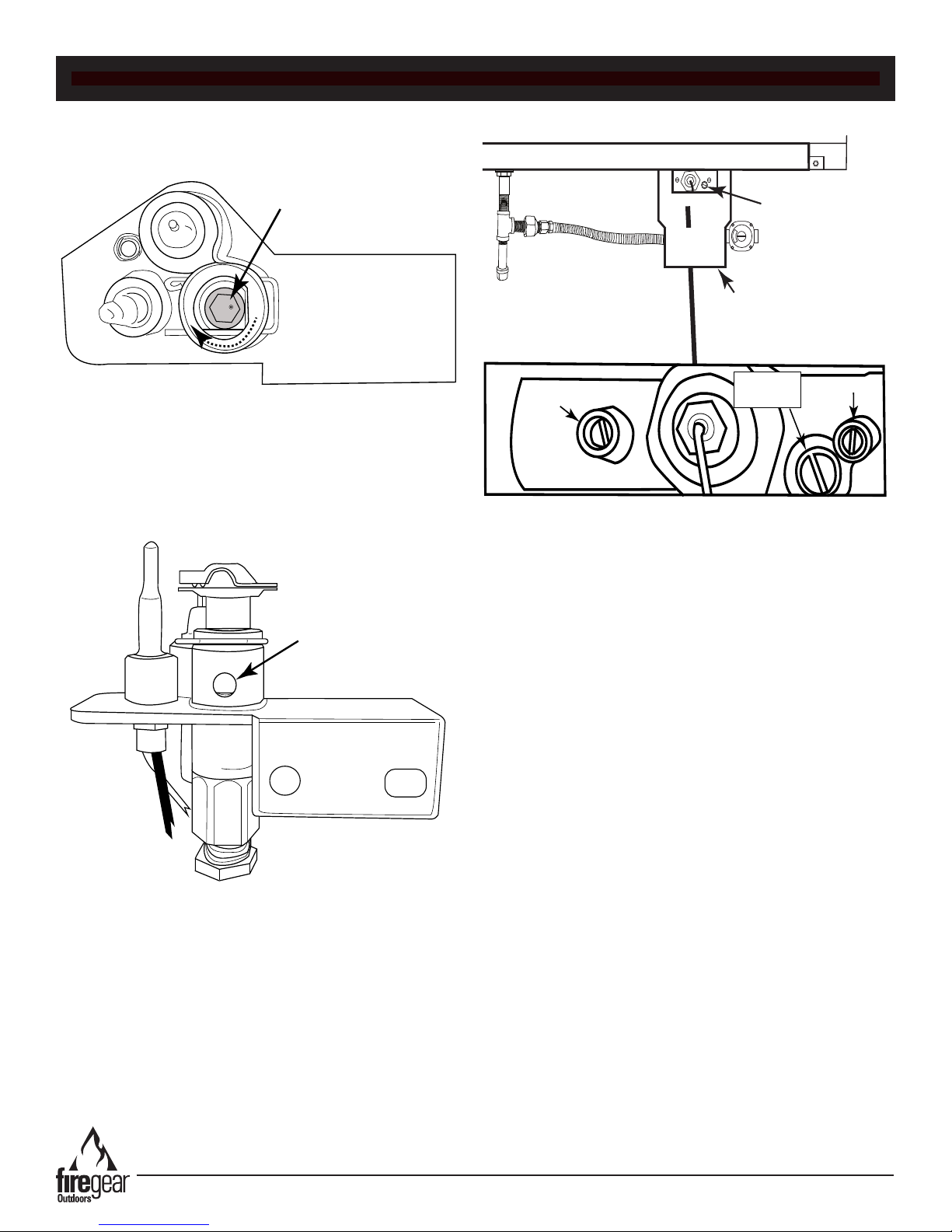
Step 9: Insert a 4mm hex head (allen wrench) into the
octagon hole of the brass orice inside the pilot assembly
and turn clockwise until it stops (approximately 2 full
revolutions). See Fig. 8.
Fig. 8 Shows slot inside pilot orice
Once the orice has been converted to LP then re-install
the pilot hood, ensure the clip is in place (if removed) and
mount the metal pilot box back into place in the same
manner you removed it from the burner pan. See Fig. 6.
Fig. 10 Detailed location of low rate set screw
Fig. 9 Pilot assembly converted to LP
NOTE: Figs. 7 and 9 provide a visual reference of the
pilot orice from Natural gas to LP gas through the vent
hole of the pilot assembly.
Step 10: Look for the low rate set screw in the gas valve
box. There is a cutout (window) area that allows access to
the low rate set screw. Fig. 10 below shows the side view
of the burner pan and a close-up detail.
Step 11: Remove the low rate set screw with a at
bladed screwdriver turning the screw counter-clockwise.
The set screw has a rubber “O” ring on the outer portion of
the screw, as a result the screw will rotate only 3-4
revolutions and not unscrew any farther. Note: If you drop
the low rate screw inside the valve area you can retrieve it
through the access door of the valve box.
Step 12: Remove the low rate set screw using a small pair
of needle-nose pliers. Grab the outer edge of the screw
and pull outward.
Step 13: Insert the correct new low rate screw from
Table 1 with the needle-nose pliers. Secure the new low
rate set screw (clockwise) with screwdriver until it is tight
and now longer spins.
CAUTION: DO NOT REMOVE OR LOOSEN THE SMALL
SET SCREWS ON EACH SIDE OF THE V-WIRE. THESE
ARE PRESSURE TEST PORTS. IF THESE ARE
LOOSENED THEY MUST BE RE-TIGHTENED TO
ENSURE NO GAS LEAKS OCCUR.
Step 14: Fill out the label “This replace has been
converted to LP gas” and afx it to the blank area on the
rating plate.
Step 15: Ensure you test the burner pan after it is installed
into the replace for any gas leaks.
Kalea Bay Outdoor Fireplace
Step 16: Conversion is now complete.
REV. 4-17-19 Page 31

FIREPLACE MAINTENANCE
1. The replace should be inspected and cleaned before rst use at the beginning of each season by a qualied eld
service person.
2. Any component that is found faulty must be replaced with an approved component.
3. Any tampering with or modifying the replace is dangerous and voids all warranties.
4. During winter months in cold climates and various seasons operation the replace may be affected by weather
conditions. It is recommended to use a weather proof cover overtop for your replace to protect it from humid/rainy
weather conditions when not in use. Heavy rains/downpours could affect the replace operation if not covered; if this
occurs ensure you allow the replace time to dry out before attempting to operate. NOTE: If a combustible type cover
is used over the replace when not in use be sure to remove it before operation to prevent a severe safety hazard.
5. Carbon (soot) may build up on the metal interior during heavy use and sooting may also occur periodically
under the pilot cover. Do the following: To clean, mix several drops of dish washing liquid into a bucket of hot water.
The dish soap assists in breaking up the soot and removing it from the metal. CAUTION: Ensure replace is cool to
touch and gas is turned OFF before cleaning.
A. Dip a scrubbing sponge into the soapy water and wipe it back and forth over the soot deposits. This breaks off
the majority of the soot from the metallic surface.
B. Spray any remaining soot deposits with a combination of warm water and white vinegar mixed in a spray bottle
in a half-and-half solution. White vinegar is slightly acidic and this helps break up the soot and cleans the metal
effectively.
C. Run a nylon scrub brush against any stubborn soot to remove it from the metal. Avoid using a metal scrub
brush since this can result in scratching.
D. Buff the metal with a damp rag to remove any remaining soap or vinegar and then dry it with a dry rag.
6. Over time stainless steel parts can discolor when heated, usually a golden or brown hue. This discoloration is normal
and does not affect the performance of the appliance.
Kalea Bay Outdoor Fireplace
REV. 4-17-19 Page 32

Symptom Remedy
Fireplace
Won’t Light
No Spark to
Ignite
1. Bleed gas line.
2. Ensure all gas lines are turned ON.
3. Ensure there is not too much media overtop the burner, it can inhibit the
gas ow. Too little or no media can also contribute to non-lighting.
4. Media blocking pilot hole. See Fig.23 on page 22.
1. Visually look at ignitor for any physical damage.
2. Ensure batteries in battery pack measure 1.5 volts each.
3. Listen closely to vent area for any beeping sound. If beeping is heard refer to page 34.
GENERAL TROUBLESHOOTING
TROUBLE SHOOTING
ADDITIONAL TROUBLE SHOOTING
Continues to
Spark after
Lighting
Low Flame
Water in my
Fireplace
Whistling Noises 1. Check media to ensure it is not too tightly packed around the burner tube.
Fireplace Won’t
Stay Lit
1. Thermocouple out of alignment.
2. Check connection of thermocouple at “S” terminal on control module to ensure it is connected.
3. Control module “proves” ame before lighting. See Ignition safety on page 34.
1. Ensure the media is at least ½” - ¾” in diameter. See page 23, Fig. 25.
2. Ensure all shut-off valves are fully open (See page 6, Fig. 1).
3. Check for spider webs inside burner orice.
4. Check gas type and gas pressure.
5. Wrong media installed into the burner trough.
6. Too much media installed overtop of the trough (See page 22, Fig. 23 for details).
1. Excess dust/sand material from media may be blocking the weep holes to relieve water. Remove
all media and unplug weep holes. Clean or install new media free of dust and dirt.
2. Ensure re pit enclosure has proper drainage for water and proper ventilation to dry out.
3. Recommend to purchase a cover (if applicable) to keep excessive water out of the re pit.
2. Ensure a non-whistling ex connector is being used.
1. Check alignment of pilot ame through ignition hole on page 22, Fig. 23.
2. Thermocouple reading should be between 10-20mV while operating. Use a multi-meter and test
at the brass ground lead on gas valve and the gold lead at “S” terminal on the control module. If
no minimum millivolts are maintained replace the thermocouple. Must test with pilot operating to
obtain readings.
3. Check continuity of thermocouple. Using a volt meter remove the TC test lead “S” from the
control module and the brass fork terminal from the gas valve. Test for continuity.
If no continuity, replace the thermocouple.
4. Ensure thermocouple is clean and free of any debris. Excessive soot can be an issue.
Sooting
1. Incorrect gas for the replace. Ensure rating label has proper model number for gas being used.
2. Too much media can cause sooting.
3. Wrong media being used. (See page 22 for details).
Kalea Bay Outdoor Fireplace
REV. 4-17-19 Page 33

ERROR CODE TROUBLESHOOTING
Error Codes
The control module has the ability to detect problems with the replace and will initiate error codes when they occur. If an
error code occurs the control module will emit a series of “beeping” patterns to determine the error. Due to the outdoor
environment, it may be difcult to hear the control module “beeping” inside the replace We suggested to “listen” at the
vents or next to the burner tube.
The error codes listed below will guide you through troubleshooting issues.
Ignition Safety Error: One short beep every one second.
Cause: Pilot did not light within the trial period of 50-60 seconds therefore step motor will turn gas valve to OFF position.
Corrective Action: Press OFF button to clear. Wait 30 seconds and try again.
Recycle Safety Error: Two short beeps every one second.
Cause: 1. Pilot automatically lights and drops out 3-times within 2-minutes causes step motor to turn gas valve to OFF
position. 2. Someone has pressed the ON/OFF button 6-times within 2-minutes causing the step motor to turn gas valve
to OFF position.
Corrective Action: Press OFF button to clear. After 5-minutes the beeping will stop then retry.
Sensor Safety Error: Four short beeps every one second (constant beeping).
Cause: Pilot ame sensor voltage too high, ground circuit not properly connected, pilot ground wire loose or not
connected, or motor not plugged into control module; therefore, step motor will turn gas valve to OFF position.
Corrective Action: Press OFF button to clear. Wait 30-seconds to thermocouple to cool down. If persist, then check other
possible causes and retry.
Thermal Safety: Four short beeps every two seconds.
Cause: System has overheated and exceeded 170°F internal temperature limit and the step motor will turn gas to OFF.
Corrective Action: Internal temperature must cool down to below 160°F then press the OFF button to clear and retry.
Communication Safety: One short beep every four seconds.
Cause: Transmitter and module are not communicating properly. Could be related to distance greater than 20-feet away
from each other or weak/dead batteries in one or the other.
Corrective Action: Module must receive a signal from transmitter
Kalea Bay Outdoor Fireplace
REV. 4-17-19 Page 34

OPTIONAL ACCESSORIES
ON
OFF
HI
LO
30 MIN
60 MIN
120 MIN
OFF
The following accessories are available from your local Firegear dealer/distributor.
Each accessory comes with a separate installation manual. Read each instruction thoroughly before installing.
Wireless Wall Switch
Wireless wall switch (ON/OFF/HI/LO)
Model: 1322-WT
Firegear Outdoors Media
GRL-Series (Reective Glass in
several colors)
Twig Set
Model: 926-930
6 piece Beach Driftwood twisted twig
set.
NOTE: Logs cannot be placed directly
on the burner. They must be placed
around the perimeter of burner.
See-Thru Conversion Kit
Wireless Wall Switch
Wireless wall switch (ON/OFF) ONLY
Model: 1001D-ATX
Home Automation System
Model: AF-4000HAT
Enables the replace to operate with a
home automation device.
Optional Remote Control
Model: RCAF-3TX
Wireless Handheld remote with Hi-Lo
features.
Power Adapters
Wireless Wall Switch Timer
4-Button Wall Timer (30/60/120/OFF)
Model: TM-R-AF1TX
LP Conversion Kit
Model:
OFP-36LECO-LPK (36-inch model)
OFP-48LECO-LPK (48-inch model)
OFP-60LECO-LPK (60-inch model)
OFP-72LECO-LPK (72-inch model)
Converts replace from Natural gas
to LP gas. See page 29 in manual.
Weatherproof Covers
73230 (36-inch model)
74230 (48-inch model)
75230 (60-inch model)
76230 (72-inch model)
Model: ADP10-OUT
ADP70-OUT
Outdoor approved 120VAC to 7.5VDC
adapter/ transformer eliminates the
Models: OFP-36COV
OFP-48COV
OFP-60COV
OFP-72COV
use of battery power with any TFS
Kit includes: hood, right/left glass
holders & screws
system.
Stainless steel cover to protect
replace during none use times.
Note: Remote controls and wall mount switches listed above are not waterproof product therefore it is strongly suggested
to install them into a waterproof enclosure or keep protected from the outside elements.
FOR TECHNICAL SERVICE, CALL:
(855) 498-8324
Firegear Outdoors
9230 Conservation Way
Fort Wayne, IN 46809
(260) 459-1703
Sales Support: (888) 699-6167
WEB SITE: www.regearoutdoors.com
Kalea Bay Outdoor Fireplace
REV. 4-17-19 Page 35

Skytech Products Group (Firegear Outdoors) hereby warrants
to the end user that products will be free from material and
workmanship defects that prevent safe and correct operation of
the product. The warranty commences from date of sale to the
end user for the following period:
End User must provide a bill of sale, canceled check, or payment
record from the end user to verify purchase date and to establish
warranty period. This Limited Warranty shall be valid and limited
to the original purchaser only.
WARNING Any modication to the product will void the warranty.
This Limited Warranty shall be limited to the repair and/or
replacement of parts that have proven to be defective under
normal use and service. Before returning any parts, contact
our Technical Service Department for a Return Materials
Authorization (RMA) number. All warranty claims must be made
by the OEM / Distributor / Dealer account on behalf of the end
user. You may contact Technical Service at (855) 498-8324.
All approved returned defects must be conrmed by our
Technical Service Department. If the defect is conrmed and we
approve the claim, we will replace such parts without charge.
This warranty gives you specic legal rights, and you may also
have other rights, which vary from state to state.
Travel, diagnostic cost, service labor to repair the defect and
freight charges on warranty parts to and from the factory will
be responsibility of the owner. We will not be responsible for
labor charges and/or damage incurred in installation, repair, and
replacement.
LIMITED WARRANTY
This Limited Warranty is voided if not assembled, installed
and operated as intended. This Limited Warranty does not
cover any defects due to accident, abuse, misuse, alteration,
misapplication, vandalism, improper installation or improper
maintenance or service, removal from the original location or
re- installation into another location, or failure to perform normal
and routine maintenance.
Damage due to severe weather conditions such as hail,
hurricanes, earthquakes, tornadoes, discoloration due to overheating, exposure to chemicals (including salt), either directly or
in the atmosphere, or very high humidity, is not covered by this
Limited Warranty.
There are no other express warranties except as set forth herein.
For consumer applications, any applicable implied warranties of
merchantability and tness are limited induration to the period
of coverage of this Limited Warranty. Some states do not allow
limitation on how long an implied warranty lasts, so this limitation
may not apply to you.
For Commercial applications, the liability of Firegear Outdoors
is limited to the express terms of this warranty. We expressly
disclaim any and all implied warranties, including any warranties
of tness for a particular purpose or merchantability.
We are not liable for any special, indirect or consequential
damages. Our maximum liability is limited to the purchase
price of the purchased products. Some states do not allow the
exclusion or limitation of incidental or consequential damages, so
this limitation or exclusions may not apply to you.
We do not authorize any person or company to assume for it any
other obligation or liability in connection with the sale, installation,
use, removal, return, or replacement of its equipment; and no
such representations are binding.
Lava Rock and Lava Stones are not
covered by warranty
CONSUMER/NON-COMMERCIAL APPLICATIONS:
Stainless Steel Components 5 Years
Gas Valve, Spark Igniter & Electronic Parts 2 Years
Log Sets 5 Years
Glass Windshields 5 Years
Glass Media 1 Year
Controls 5 Years
AnF Enclosures 5 Years
GFRC (Glass Fiber Reinforced Concrete) 1 Year
COMMERCIAL APPLICATIONS:
Stainless Steel Components 1 Year
Gas Valve, Spark Igniter & Electronic Parts 1 Year
Log Sets 1 Year
Glass Windshields 1 Year
Glass Media 1 Year
Controls 1 Year
AnF Enclosures 1 Year
GFRC (Glass Fiber Reinforced Concrete) 1 Year
Lava Rock and Lava Stones are not
covered by warranty
A DIVISION OF SKYTECH PRODUCTS GROUP
REV. 6/18
Kalea Bay Outdoor Fireplace
REV. 4-17-19 Page 36

Notes:
Kalea Bay Outdoor Fireplace
REV. 4-17-19 Page 37

Having problems getting the replace to operate? Don’t leave the job site!
We want to help! Call 855.498.8324 for Technical Support
between the hours of 8:00AM to 5:00PM EST.
Text photos to 260.255.5750 or e-mail photos to support@skytechpg.com
BEFORE YOU CALL WE WILL NEED THIS INFORMATION
1. Model Number: ___________________________
2. Serial Number: ___________________________
3. How long is the gas line run? Nat Gas ____ LP Gas ____
4. What size is gas line? _____
5. Inlet Gas Pressure: _____WC
Manifold Gas Pressure: _____ WC
6. What type of media are you using? __________________
7. Review the troubleshooting section in the installation manual.
8. What are the symptoms? Please be prepared to explain.
9. Be prepared to send photos to us when on the phone.
10. Found missing or damaged parts? Let us know ASAP or send photos.
Kalea Bay Outdoor Fireplace
REV. 4-17-19 Page 38
 Loading...