


MODELS
Natural Gas Description
LOF-30MT-N 30-inch stainless tube burner & pan
LOF-36MT-N 36-inch stainless tube burner & pan
Linear Outdoor Fire Pit (LOF)
Installation and Operating Instructions
IF YOU CANNOT READ OR UNDERSTAND THESE INSTALLATION INSTRUCTIONS DO
NOT ATTEMPT TO INSTALL OR OPERATE THIS APPLIANCE
INSTALLATION PRECAUTION:
This Linear Outdoor Fire pit requires a minimum 18-square inches (per side) of cross
ventilation. Failure to provide proper ventilation can void the warranty.
Warning: For Outdoor Use Only
PLEASE RETAIN THIS MANUAL FOR FUTURE REFERENCE

CARBON MONOXIDE HAZZARD
DANGER
This appliance can produce carbon monoxide
which has no odor.
Using it in an enclosed area can kill you.
Never use this appliance in an enclosed space
such as a camper, tent, car or home.
DANGER
If you smell gas:
1. Shut off gas to the appliance.
2. Extinguish any open ame.
3. If odor continues, keep away from
the appliance and immediately call
your gas supplier or re department.
WARNING
Do not store our use gasoline or other
ammable vapors and liquids in the
vicinity of this or other appliances.
Any LP cylinder not connected for use
shall not be stored in the vicinity of this
or other appliances.
WARNING
Do not leave unattended during use.
Do not use for cooking.
Follow all gas leak procedures in this
manual prior to operation.
Improper installation, adjustment,
alteration, service or maintenance
can cause injury of property damage.
WARNING
Read the installation, operating and
maintenance instructions thoroughly
before installing or servicing this
equipment.
WARNING
If the information in these instructions is not followed exactly, a re or explosion
may result causing property damage, personal injury or death.
FOR YOUR SAFETY
Do not store or use gasoline or other ammable vapors and liquids in the vicinity
of this or other appliance.
Fuels used in gas red appliances, and the products of combustion of such fuels,
contain chemicals know to the State of California to cause cancer, birth defects and/or
other reproductive harm. This warning is issued pursuant to California Health & Safety
Code Sec. 25249.1
Linear Outdoor Fire (LOF)
REV. 2-4-19 Page 2

CALIFORNIA PROPOSITION 65
WARNING
This product is designed to operate with one of the following fuel sources: Liquid Propane or Natural Gas. The fuel
used to operate this product, and the products of combustion of such fuel, can expose you to chemicals including
Benzene which is known to the State of California to cause cancer, birth defects and other reproductive harm and
Carbon Monoxide which is known to the State of California to cause birth defects or other reproductive harm.
(For more information go to: www.p65Warnings.ca.gov.)
TABLE OF CONTENTS
Specications 4
Gas Pipe Sizing 5
Preparation for Non-Conbustible Structure 6
Hard Piping to Linear Outdoor Fire 6
Cross Ventilation Requirements 6
High Elevation 6
Installation into an Approved Enclosure 7
Requirements 7
Installing Orice & Key Valve 8
Installation of Lava Rock/Media 8
Typical Installation Drawings 9
Expanded View Drawing 10
Operation 11
Lighting Instructions 11
Replacement Parts 12
Replacement Parts List 12
Maintenance/ Trouble Shooting 13
Optional Accessories 14
All media (i.e. lava rock, lava stones, lava boulders and re glass) has the potential of thermal
spalling. This is a process that may occur when media is wet and moisture gets trapped inside of
the material due to rapid temperature differences. When this happens the media has the potential
WE HIGHLY RECOMMEND COVERING ALL FIRE FEATURES WHEN NOT IN USE
The use of a cover can lessen the impact of thermal spalling; however, heavy rains, high
humidity and the presence of moisture may still cause the media to pop.
ALWAYS USE CAUTION WHEN USING THE FIRE FEATURE
Extra caution should be taken when lighting a replace when heavy rains, high humidity and
moisture are present. Light the replace; leave the area allowing any moisture in the media to
dissipate. We strongly recommend that during this drying out time that you monitor the re feature
from a distance. This drying out period should be no less than 30 minutes. Continue monitoring
the ame from distance to ensure that all popping has ceased before fully enjoying the re.
Linear Outdoor Fire (LOF)
to crack or “pop” outside the replace.
REV. 2-4-19 Page 3

SPECIFICATIONS
Ground Level
A
B
C
D
End View
96”
36”
18”
C
L
24”
Max
Overhang
Model
Min/Max Opening Width - LengthAPan
Depth
LOF-30MT-N 6 ¼”- 7 ½” W x 30 ¼”- 31 ¾” L 2 ¾” 32” x 8” 30” x 6” 6” 18”
LOF-36MT-N 6 ¼”- 7½” W x 36 ¼”- 37 ¾” L 2 ¾” 38” x 8” 36” x 6” 6” 18”
Table1 LOF Pan Dimensions
Fig. 1 Linear Pan Dimensions; refer to Table 1.
Model Btu’s
NG/(LP)
LOF-30MT-N 45,000 Btu’s #36 #49
LOF-36MT-N 75,000 Btu’s #29 #41
Table 2 Btu Specications based on 7.0”WC - NG and 10.0”WC -LP
Factory Orice
NG LP
B
Outside
Pan
C
Inside
Pan
Pressure NG LP
Min. Inlet 5.0”WC 11.0”WC
Max. Inlet 10.5”WC 13.0”WC
Table 3 Gas Pressures
D
Ground
Level
Combustible
Floor
E
Note: Linear Outdoor Fire’s are rated at maximum Btu’s which is
dependent upon proper gas pipe sizing. Flex line size also affect Btu’s.
As a result your Btu’s will may vary from Table 2 specications listed above.
Fig. 2 Clearance to Combustibles (Not
to be used in an enclosed space)
Linear Outdoor Fire (LOF)
REV. 2-4-19 Page 4

REFERENCE
GAS PIPE SIZING
Length of Pipe in Feet
1/2” 3/4” 1” 1 - 1/4” 1 - 1/2” 2” 2 - 2 1/2” 3” 4”
10 275 567 1071 2205 3307 6221 10140 17990 35710
20 189 393 732 1496 2299 4331 7046 12510 25520
30 152 315 590 1212 1858 3465 5695 10110 20620
40 129 267 504 1039 1559 2992 4778 8481 17300
50 114 237 448 913 1417 2646 4343 7708 15730
60 103 217 409 834 1275 2394 3908 6936 14150
70 89 185 346 724 1086 2047 3329 5908 12050
80 78 162 307 630 976 1811 2991 5309 10830
90 69 146 275 567 866 1606 2654 4711 9613
100 63 132 252 511 787 1496 2412 4281 8736
125 54 11 2 209 439 665 1282 2083 3618 7382
150 48 100 185 390 590 1138 1808 3210 6549
175 43 90 168 353 534 1030 1637 2905 5927
200 40 83 155 325 491 947 1505 2671 5450
300 37 77 144 303 458 887 1404 2492 5084
NATURAL GAS : PIPE SIZING CHART
•
Natural Gas (NG) flow is given in
thousands of BTU/hr. = 1 cubic
foot of NG gas - 1000 BTU
•
Nominal pressure at the burner
for Natural Gas is 3.5” of water
column. (Typical machine supply
5”-7”)
•
Pipe length must include
additional length for all fittings.
Add approximately 5 fe et of pipe
per fitting.
•
Natural Gas Example: A machine
with a burner that requires
440,000 BTU would need a 1 -1/4”
pipe for a 20” long run.
LIQUID PROPANE : PIPE SIZING CHART
NOTE: The sizing charts above list the specific pipe sizes required for the amount of BTU’s for a new gas line installations. If you
are using an existing gas line you must take into consideration the existing gas line capacities to ensure you will have proper
pressure. This chart is for reference only, we recommend you consult with a Licensed Plumber/Gas Fitter or NFPA54 (National Fuel
Gas Code - current edition) for more details.
Length of Pipe in Feet 1/2” 3/4” 1” 1 - 1/4” 1 - 1/2” 2” 2 - 2 1/2” 3” 4”
10 108 230 387 793 1237 2259 3640 6434 -
20 75 160 280 569 877 1610 2613 5236 9521
30 61 129 224 471 719 1335 2165 4107 7859
40 52 11 0 196 401 635 1143 1867 3258 6795
50 46 98 177 364 560 1041 1680 2936 6142
60 42 89 159 336 513 957 1559 2684 5647
70 38 82 149 317 476 896 1447 2492 5250
80 36 76 140 239 443 840 1353 2315 4900
90 33 71 133 275 420 793 1288 2203 4667
100 32 68 126 266 4 11 775 1246 2128 4518
125 28 60 117 243 369 700 1143 1904 4065
150 25 54 105 215 327 625 1008 1689 3645
175 23 50 93 196 303 583 993 1554 3370
200 22 47 84 182 280 541 877 1437 3160
300 17 37 70 145 224 439 686 1139 2539
•
Liquid Propane (LP) Gas flow is
given in t hou sands of BTU/hr. =
1 cubic foot of LP gas - 2500 BTU.
•
This chart refers to low pressure LP,
after regulation, Standard nominal
pressure at the burner for Liquid
Propane Gas is 11” of water column.
•
Pipe length must include additional
length for all fittings. Add
approximately 5 feet of pipe per
fitting.
•
LP Example: A machine with a
burner that requires 440,000 BTU
would need a 1” pipe for a 20’ long
run.
GAS PIPE SIZING CHART
Table 4: Gas Pipe Sizing Chart
Linear Outdoor Fire (LOF)
REV. 2-4-19 Page 5

WARNING: Proper clearances from combustible, construction and materials must be maintained from all sides, top and
bottom of this appliance. This appliance should never be placed on any combustible surface. This appliance should
never be placed under any combustibles closer then 96-inches. This appliance should never be placed closer than
36-inches from any side to any combustible construction or materials (See g. 2, pg. 4).
PREPARING A NON-COMBUSTIBLE STRUCTURE
The Linear Outdoor Fire is to be installed on a at, stable surface, away from any combustible materials. Install Linear
Outdoor Fire on any level, outdoor non-combustible surface. NOTE: Do not place Linear Outdoor Fire directly on grass,
dirt, or rocks this may prevent proper ventilation (Table 1, pg. 4). Ensure proper water drainage is also incorporated
into the Linear Outdoor Fire enclosure.
HARD PIPING TO Linear Outdoor Fire pit WITHOUT GAS PROXIMITY
NOTE: We recommend using a minimum ¾” black iron pipe however refer to the NFPA54 (National Fuel Gas Code) for
proper pipe sizing when exceeding 20-feet in length for Linear Outdoor Fire’s rated above 100,000 Btu’s.
1. Turn OFF gas supply system. NOTE: All gas connections (except for brass to brass) require the following. Clean pipe
threads using either a wire brush or steel wool. Apply Teon tape or pipe sealant to the steel ttings before making any
connection. BE CAREFUL! Ensure all gas connections are snug, but not over tighten!
2. Extend the gas supply system using minimum of ¾” black iron pipe or an approved exible gas line from existing house
supply. This can be accomplished by teeing off or tapping into a convenient gas line connection. Install necessary pipe
for the distance required and then install a manual shut-off valve at the exterior house wall. If pipe is to pass through a
foundation or house wall, make sure to re-seal the area around the pipe with weather sealant.
3. the primary shut-off (not supplied) will reguire a 1/2” male ared tting to enable connection of stainless steel ex
IMPORTANT
Installation of Natural or LP gas should be done by a qualied installer, service agency or gas supplier.
The appliance and its manual shutoff valve must be disconnected from the gas supply piping system during any
pressure testing of the system at test pressure testing of the system at test pressures in excess of ½ psig (3.5kPa).
This appliance must be isolated from the gas supply piping system by closing its manual shutoff valve during any
pressure testing of the gas supply piping system at test pressures equal to or less than ½ psig (3.5kPa)
NOTE: LP conversion kits are available in the Accessory/
Conversion Kit section of this manual. When converting a Linear
Outdoor Fire ensure you follow the instructions supplied with the
conversion kit.
VENTILATION FOR NON-COMBUSTIBLE ENCLOSURE
Linear Outdoor Fire’s are subjected to many outdoor
elements such as rain, snow, wind, heat or cold. A minimum
of 18 square inches of cross ventilation (2 sides) is
required to keep the components in good working order.
Use gure 3 as guide to assist to incorporate proper
ventilation. NOTE: Ventilation is not required at the bottom, it
may also be incorporated in the upper portion of an enclosure.
HIGH ELEVATION INSTALLATION
This appliance is listed for elevations from 0-4500 feet in
Canada and the U.S. If elevation exceeds 4500 feet it may be
necessary to decrease the input rating by changing the exist-
ing burner orice to a smaller size. Input should be reduced
4% for each 1000 feet beyond the 4500 feet above sea level.
Check with your local gas utility for assistance in determining
the proper orice in your location. In some cases the heating
value may already be reduced and downsizing the orice may
not be necessary.
Examples of Cross Ventilation
3 - 2”x3” Slots Per Side or
2 - 1” x 9” Slots Per Side or
2- Firegear 6 x12 vents
Fire Pit
Fire Pit
Enclosure
(2) 6”x12”
Cross Flow Ventilation
(Min. 18 Sq. In. Per Side)
Linear Outdoor Fire (LOF)
Fig. 3 Cross Ventilation Example
REV. 2-4-19 Page 6

INSTALLATION OF INTO AN APPROVED ENCLOSURE
REQUIREMENTS
1. Only non-combustible materials should come in direct contact with any part of the Linear Outdoor Fire. Under
neath area should be non-combustible as well.
2. Only a minimum ¾” gas supply line to the Linear Outdoor Fire. Based on the selection of the Linear Outdoor Fire
size, the proper brass ttings should be used to ensure a proper installation.
3. Determine the size of the round or square Linear Outdoor Fire you are preparing to install (Refer to page 4).
4. You must provide a rectangular opening out to place the Linear Outdoor Fire into the non-combustible
enclosure surround. Do not exceed the maximum opening from Table 1, dimension B.
5. Follow the local code requirements for the gas type being used. This Linear Outdoor Fire should be installed in
accordance with local codes and ordinances or in the absence of local codes, with the latest National Fuel Gas
Code, ANSI Z223.1 NFPA54 or CSA B149.1, Natural and Propane Installation Code in Canada.
6. Linear Outdoor Fire pits create high temperatures, it is very important to have any combustibles at a safe distance
See Fig. 2 page 4).
7. CAUTION: A minimum of 18 square inches of cross ventilation (per side) is required to keep the enclosure
dry.
8. These products are designed for outdoor use only. Not approved for any indoor use.
9. This Linear Outdoor Fire is designed to have Lava Rock/Media completely covering the burner tube so that the
burner is invisible. Do not cover more than 1” above the top of the burner. When purchasing Lava Rock it is recom
mended to use minimum of 1” diameter as a base to ll the burner pan. Decorative glass covering may be loosely
scattered on top of the rock if desired or non-combustible logs may be added for a campre look. If logs are
chosen, do not place on decorative glass base, use only Lava Rock as the base. NOTE: If using all glass media,
glass must be a minimum of ½”- ¾” diameter or larger.
10. Gas lines and ttings must be installed in to the non-combustible structure. All gas connections must be leak tested
before installation of the Linear Outdoor Fire. Soapy water leak detection is required before regular use of the
Linear Outdoor Fire.
11. Do not use material that will absorb moisture over time and will not release this moisture quickly. Moisture can boil
in this material and can rapidly break apart and cause damage or personal injury.
12. Never leave any other combustible material on top of the Linear Outdoor Fire. This could cause unsafe operation
of this system and damage to the component that will not be covered under our warranty.
13. Cover the complete burner with lava or decorative Rock material (min. 1-inch diameter). Completely cover the
star burner, no more than 1-inch above the restar burner.
Linear Outdoor Fire (LOF)
REV. 2-4-19 Page 7

INSTALLING BURNER ORIFICE (OAS)
GAS FLOW
Burner Pan
OAS#
U3-8D-S
Lock Nut
Locate the burner nipple underneath the
burner pan. Ensure the nipple from on
the spur burner has gas rated Teon tape
wrapped around the threads. Thread the
OAS (orice air shutter) on to the nipple
of the burning spur clockwise manner.
Secure into position. See Fig. 4.
Fig. 4 Installing orice.
INSTALLING KEY VALVE AND PIEZO IGNITOR
The key valve contents: 1- key valve, 1- key and 1- ange. (See Fig 5). The valve requires a 1 ¼” round clearance hole
in the non-combustible enclosure wall. See the instructions supplied with the key valve for more specic details. Note: Be
sure to leak test all tting before operation. Fig. 6 shows an example of a typical installation.
After the Linear Outdoor Fire burner pan is installed run the Piezo ignitor wires into the electrical junction box. Piezo wires
are 24-inches in length; ensure your installation does not exceed the wire length for proper connection.
OFF
ON
Primary Gas
Supply
Fig. 5 Key valve components.
INSTALLATION OF LAVA ROCK/MEDIA INTO BURNER PAN
Install lava rock/media into the burner pan. Ensure the media is a minimum of 1-inch diameter for proper operation.
Note: Do not pour Lava Rock directly from bag. Media should be placed naturally and NOT packed in tight. Loose tting is
important to ensure robust ames. Be sure rocks are free of any excessive dust. This prevents the burner pan weep holes
from being plugged and holding water.
Cover the burner completely with media but do not make the depth greater than 1-inch overtop of the burner portholes.
Decorative glass may be loosely scattered on top of the lava rock. Do NOT cover the stainless steel screen cover with
any rock or glass. It must be free an any debris to operate properly.
Linear Outdoor Fire (LOF)
REV. 2-4-19 Page 8
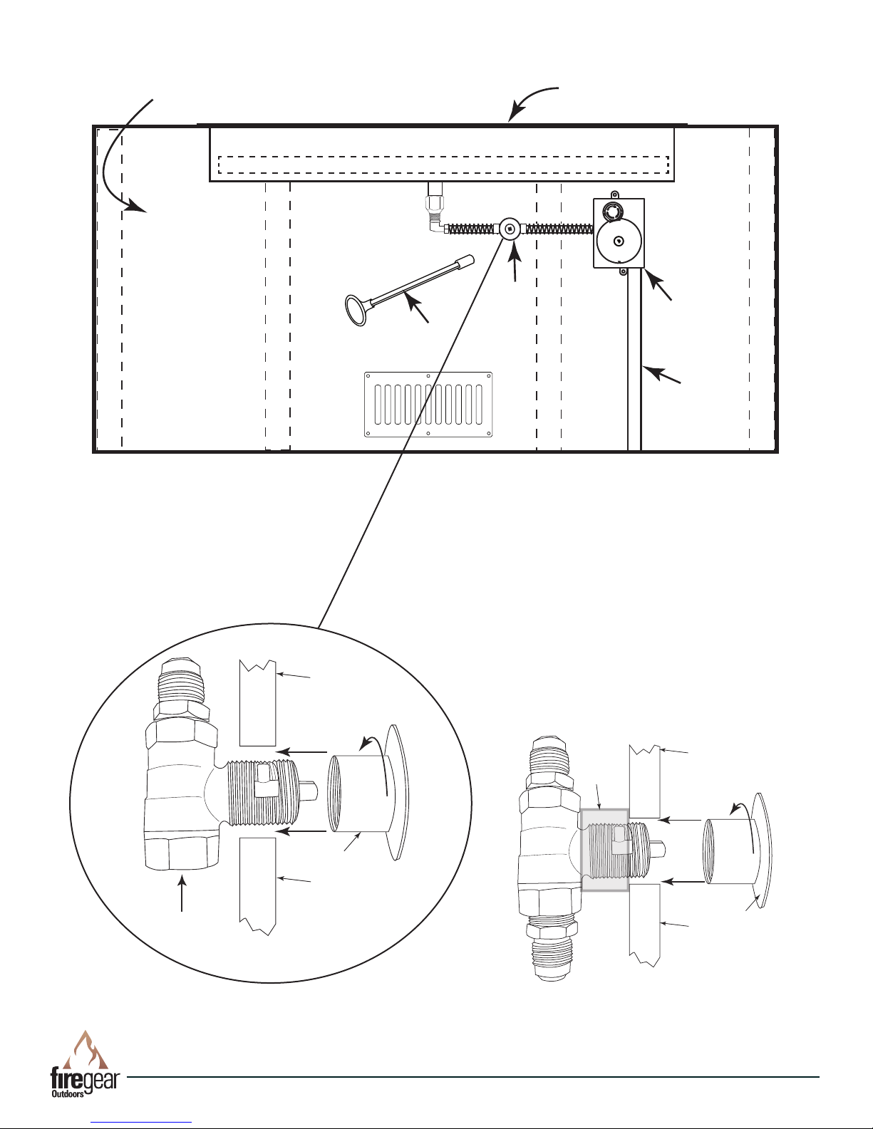
Non-Combustible
Key Valve Flange
NonCombustible
Wall Material
Non-
Combustible
Wall Material
Key Valve
Primary Gas
Supply
Fire Pit Enclousure
Fire Pit Pan
PUSH TO STOP
TURN TO START
OFF
0.5
2.5
1
HOURS
2
1.5
Steel Studs
Steel Studs
K
e
y
Steel Studs
Key
Valve
E-Stop
Gas Valve
Key
Gas
Supply
Steel Studs
NOTE: E-Stop valve and ex line to
the key valve are not supplied.
i
d
S
e
v
l
a
V
e
V
i
e
w
D
e
t
a
i
l
Note: A 1¼” x 2” black iron or galvanized
coupler/nipple (not supplied) can be used
as a spacer between the manual valve
and the valve ange to add additional
support to hold the manual key valve in
place.
Fig. 6 Typical Installation
Linear Outdoor Fire (LOF)
Key Valve
Black Iron
Nipple
NonCombustible
Wall Material
NonCombustible
Wall Material
REV. 2-4-19 Page 9
Key Valve Flange
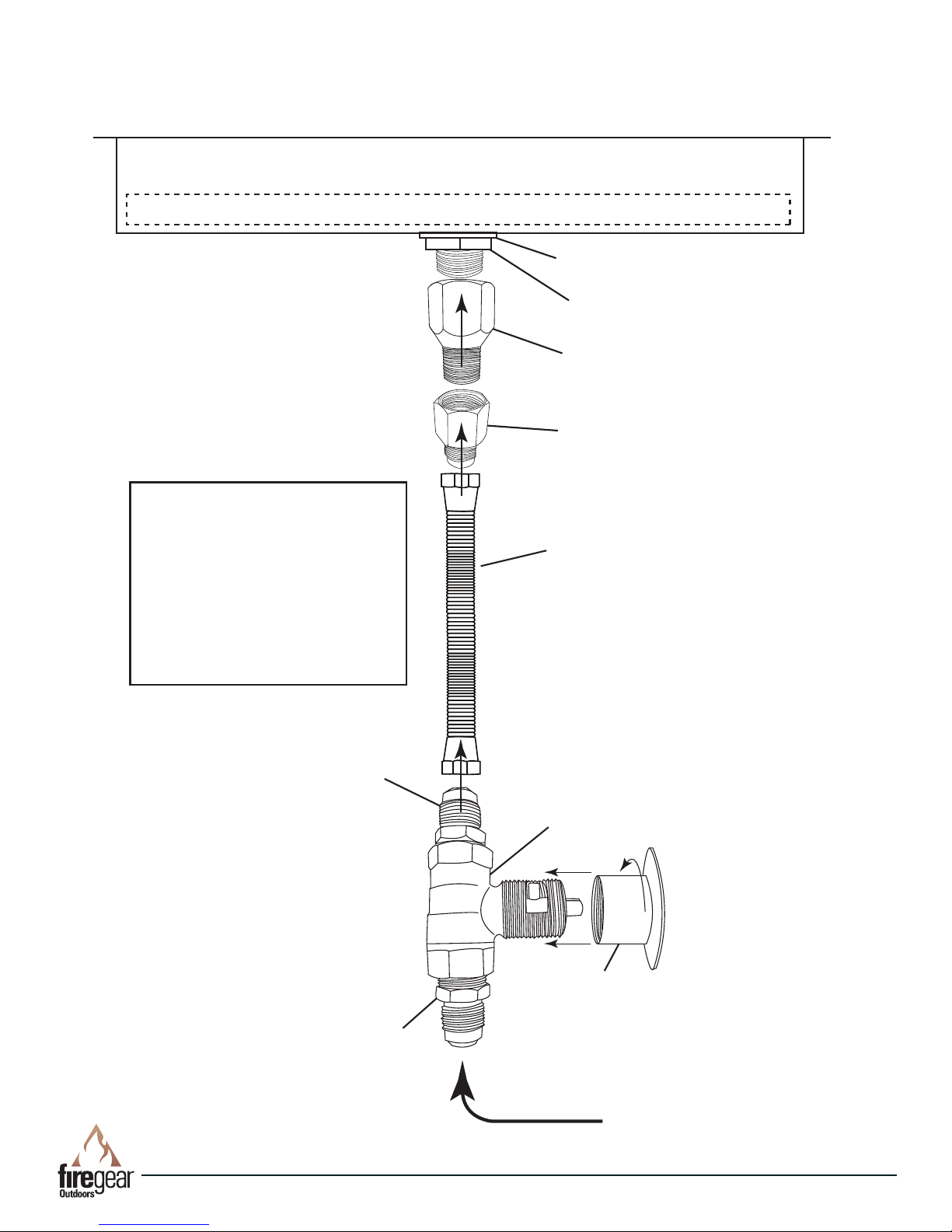
Expanded View of Match Throw (LOF) Fire Pits
/” Washer
Brass Nut
OASNG#
(Burner Orice)
U3-8D-S
(Fitting)
Note: Use joint compound or
Teon tape resistant to all
gasses on all male NPT
threads; not ared ttings.
Ensure all connections are
tight and check for gas leaks
before and after assembly is
complete.
T200-9898-46
(Flex Connector)
U1-8D-S
(Fitting)
U1-8D-S
(Not Supplied)
Linear Outdoor Fire (LOF)
BVS
(Manual Key Valve)
KC-PC
(Decorative Flange)
Inlet Gas Supply
REV. 2-4-19 Page 10

OPERATION
CAUTION: Children and adults should be alerted to the hazards on high surface temperatures and should stay away to
avoid burns or clothing ignition. Young children should be carefully supervised when they are in the area of the appliance.
WARNING: Do not use this appliance if any part has been under water. Immediately call a qualied service technician
to inspect the appliance and to replace any part of control system and any gas control, which has been under water.
SAFETY WARNINGS
1. Never leave the Linear Outdoor Fire unattended during operation.
2. Clothing or other ammable materials should not be placed on or near the appliance.
3. Any guard or other protective device removed for servicing the appliance must be replaced prior to operating the
appliance.
4. Installation and repair should be done by a qualied service person. The appliance should be inspected before
use and at least annually by a qualied service person. More frequent cleaning may be required as necessary. It
is imperative the control compartment, burners and circulating air passageways of the appliance be kept clean.
5. Inspect the fuel supply connection before each use of the appliance.
6. Temporary storage of this appliance indoors is permissible only if it has been disconnected from its fuel supply
(Natural or L.P. gas line).
WARNING
1. This appliance is hot when operated and can cause sever burns if contacted.
2. Do not burn any solid fuels in this appliance.
READ ALL LIGHTING INSTRUCTIONS BEFORE ATTEMPTING TO LIGHT
Note: If using an E-Stop valve kit ensure it is turn ON before beginning ingition of this re pit.
OFF
ON
MATCH THROW LIGHTING INSTRUCTIONS
CAUTION: Ensure you have leak tested the Linear Outdoor Fire before operating.
1. Insert key into gas valve.
2. Light a long match or butane lighter and hold it near the burner.
3. Rotate the key counter-clockwise in gas valve to allow gas to ow and simultaneously apply the burning match as
close to burner as possible to light the Linear Outdoor Fire.
4. Gas should ignite within 10 seconds or less. If Linear Outdoor Fire does not light within 10 seconds turn key clock-
wise to turn OFF the gas supply. Ensure there is not too much media on top of burner that might inhibit gas ow and
try again.
Fig. 7. Key Valve Face
Butane Lighter
Key
Fig. 8 Inserting Key into Valve
Linear Outdoor Fire (LOF)
Fig. 9 Lighting re pit with lighter
REV. 2-4-19 Page 11

1
REPLACEMENT PARTS
6
3
2
DRAWINGS NOT TO SCALE
7
8
9
REPLACEMENT PARTS
4
5
OFF
ON
Item
1 30” Pan and Burner Tube only
1 36” Pan and Burner Tube only
2 Cover Plate
3 Silicone Rubber Washer
4 7/8” Flat Washer/Spacer
5 1/2” Flex Gas Line (46-inch Length)
6 Orice Air Shutter (LOF-30 NG)
6 Orice Air Shutter (LOF-30 LP)
6 Orice Air Shutter (LOF-36 NG)
6 Orice Air Shutter (LOF-36 LP)
7 Std.Capacity Straight Ball Valve
8 12-inch Chrome Key for BVSL2S
9 Chrome Flange (decorative chrome cover for BVSL2S)
1/2” MIP Brass Lock Nut (not shown)
10
Description
Qty.
1 LOF-30
1 LOF-36
1 ST3-100-1043
1 ORING
1 WASHER10SS
1 OAS-NG36
1 OAS-LP49
1 OAS-NG29
1 OAS-LP41
1 BVL2S
1 CVR-BVL2CP
1 105-8
Part Number
T-200-9898-46
KEY-PC-12
Linear Outdoor Fire (LOF)
REV. 2-4-19 Page 12

MAINTENANCE
1. The Linear Outdoor Fire should be inspected and cleaned before initial use annually by a qualied eld service person.
2. Any component that is found faulty must be replaced with an approved component.
3. Any tampering or modifying with the Linear Outdoor Fire is dangerous and voids all warranties.
4. During winter months in cold climates and various seasons operation the Linear Outdoor Fire may be affected by
weather conditions. It is recommended to use a ventilated cover overtop of your Linear Outdoor Fire to protect it from
humid/rainy weather conditions when not in use. Heavy rains/downpours could affect the Linear Outdoor Fire operation if not covered; if this occurs ensure you allow the Linear Outdoor Fire time to dry out before attempting to operate.
NOTE: If a combustible type cover is used over the Linear Outdoor Fire when not in use be sure to remove it before
operation to prevent a severe safety hazard.
5. Carbon (soot) may build up on the surface of logs (if installed) during heavy use. Sooting may also occur periodically
on the screen of the ignitor hood. To clean, brush off with a dry bristle brush or cloth. Keep soot away from clothing
of furniture.
6. Over time stainless steel parts discolor when heated, usually a golden or brown hue. This discoloration is normal and
does not affect the performance of the appliance.
TROUBLE SHOOTING
Symptom Remedy
Unit Won’t Light 1. Ensure key valve is fully open.
2. Bleed gas line.
3. Ensure all gas supply lines are turned ON.
4. Ensure there is not too much media overtop of burner; it can inhibit gas from owing.
5. Ensue E-Stop if turned ON (if applicable).
Low Flame 1. Ensure the media is at least 1-inch in diameter and top media is no more than 1-inch over
top of burner.
2. Adjust air shutter at bottom of Linear Outdoor Fire pit pan.
3. Ensure all shut-off valves and key valve is fully open. See page 11; Fig. 7.
Water in Fire Pit 1. Excess dust/sand material from media may be blocking the weep holes to relieve water.
Remove all media and unplug weep holes. Clean or install new media free of dust and dirt.
2. Ensure Linear Outdoor Fire pit enclosure has proper drainage for water and proper ventilation
to dry out.
Linear Outdoor Fire (LOF)
REV. 2-4-19 Page 13

ACCESSORIES
The following accessories are available from your local Firegear dealer/distributor. Each accessory comes with a
separate installation manual. Read each instruction thoroughly before installing.
Lava Stones
Lava Stones: 1” to 2” size (15lbs)
Model: FG-LS15
E-Stop
Mechanical timer and gas shut off with
emergency shut-off
Model: ESTOP1-0H
Model: ESTOP2-5H
Vents
(2) 6x12 vents to provide 18 sq.in. of
cross ventilation into the enclosure.
Model: VENT-6X12SS
Lava Boulders
Lava Boulders: 6” to 12” size (30lbs)
Model: FG-LB30
LP Converstion Kits
Model: OAS-49 for LOF30
Model: OAS-41 for LOF36
LIDS
Stainless steel cover to protect re pit
when not in use.
Model: LID-LOF30
Model: LID-LOF36
Lava Rock
Lava Rock: 1” to 2" size (10lbs)
Model: FG-LAVA-10
FG-LAVA-50
Flexframe
Universal brackets to support re
pit disc when using paver blocks or
other non-combustible enclosures.
Model: FLEXFRAME-SS
Note: Media such as Lava Rock or Lava Stoves are not supplied but required as described in page 7. The Lava
boulders can be added on top of the lava rock in place of traditional logs or you can use the Lava stoves in place of the
lava rock.
FOR TECHNICAL SERVICE, CALL:
Canadian Inquires: (877) 472-3923
Web Site: www.regearoutdoors.com
(855) 498-8324
Firegear Outdoors
9230 Conservation Way
Fort Wayne, IN 46809
Sales: (888) 672-8929
Sales Support: (888) 699-6167
Linear Outdoor Fire (LOF)
REV. 2-4-19 Page 14

Skytech Products Group (Firegear Outdoors) hereby warrants
to the end user that products will be free from material and
workmanship defects that prevent safe and correct operation of
the product. The warranty commences from date of sale to the
end user for the following period:
End User must provide a bill of sale, canceled check, or payment
record from the end user to verify purchase date and to establish
warranty period. This Limited Warranty shall be valid and limited
to the original purchaser only.
WARNING Any modication to the product will void the warranty.
This Limited Warranty shall be limited to the repair and/or
replacement of parts that have proven to be defective under
normal use and service. Before returning any parts, contact
our Technical Service Department for a Return Materials
Authorization (RMA) number. All warranty claims must be made
by the OEM / Distributor / Dealer account on behalf of the end
user. You may contact Technical Service at (855) 498-8324.
All approved returned defects must be conrmed by our
Technical Service Department. If the defect is conrmed and we
approve the claim, we will replace such parts without charge.
This warranty gives you specic legal rights, and you may also
have other rights, which vary from state to state.
Travel, diagnostic cost, service labor to repair the defect and
freight charges on warranty parts to and from the factory will
be responsibility of the owner. We will not be responsible for
labor charges and/or damage incurred in installation, repair, and
replacement.
LIMITED WARRANTY
This Limited Warranty is voided if not assembled, installed
and operated as intended. This Limited Warranty does not
cover any defects due to accident, abuse, misuse, alteration,
misapplication, vandalism, improper installation or improper
maintenance or service, removal from the original location or
re- installation into another location, or failure to perform normal
and routine maintenance.
Damage due to severe weather conditions such as hail,
hurricanes, earthquakes, tornadoes, discoloration due to overheating, exposure to chemicals (including salt), either directly or
in the atmosphere, or very high humidity, is not covered by this
Limited Warranty.
There are no other express warranties except as set forth herein.
For consumer applications, any applicable implied warranties of
merchantability and tness are limited induration to the period
of coverage of this Limited Warranty. Some states do not allow
limitation on how long an implied warranty lasts, so this limitation
may not apply to you.
For Commercial applications, the liability of Firegear Outdoors
is limited to the express terms of this warranty. We expressly
disclaim any and all implied warranties, including any warranties
of tness for a particular purpose or merchantability.
We are not liable for any special, indirect or consequential
damages. Our maximum liability is limited to the purchase
price of the purchased products. Some states do not allow the
exclusion or limitation of incidental or consequential damages, so
this limitation or exclusions may not apply to you.
We do not authorize any person or company to assume for it any
other obligation or liability in connection with the sale, installation,
use, removal, return, or replacement of its equipment; and no
such representations are binding.
Lava Rock and Lava Stones are not
covered by warranty
CONSUMER/NON-COMMERCIAL APPLICATIONS:
Stainless Steel Components 5 Years
Gas Valve, Spark Igniter & Electronic Parts 2 Years
Log Sets 5 Years
Glass Windshields 5 Years
Glass Media 1 Year
Controls 5 Years
AnF Enclosures 5 Years
GFRC (Glass Fiber Reinforced Concrete) 1 Year
COMMERCIAL APPLICATIONS:
Stainless Steel Components 1 Year
Gas Valve, Spark Igniter & Electronic Parts 1 Year
Log Sets 1 Year
Glass Windshields 1 Year
Glass Media 1 Year
Controls 1 Year
AnF Enclosures 1 Year
GFRC (Glass Fiber Reinforced Concrete) 1 Year
Lava Rock and Lava Stones are not
covered by warranty
A DIVISION OF SKYTECH PRODUCTS GROUP
REV. 6/18
Linear Outdoor Fire (LOF)
REV. 2-4-19 Page 15

Having problems getting the re pit to operate? Don’t leave the job site!
We want to help! Call 855.498.8324 for Technical Support
between the hours of 8:00AM to 5:00PM EST.
Text photos to 260.255.5750 or e-mail photos to support@skytechpg.com.
BEFORE YOU CALL WE WILL NEED THIS INFORMATION
1. Model Number: ___________________________
2. Serial Number: ___________________________
3. How long is the gas line run? Nat Gas ____ LP Gas ____
4. What size is gas line? _____
5. Inlet Gas Pressure: _____WC
Manifold Gas Pressure: _____ WC
6. What type of media are you using? __________________
7. Review the troubleshooting section in the installation manual.
8. What are the symptoms? Please be prepared to explain.
9. Be prepared to send photos to us when on the phone.
10. Found missing or damaged parts? Let us know ASAP or send photos.
Linear Outdoor Fire (LOF)
REV. 2-4-19 Page 16
 Loading...