

Firegear LOF-30LTTMSI-N, LOF-36LTTMSI-N, LOF-30LHTMSI-N, LOF-36LHTMSI-N Installation And Operating Instructions Manual

Warning:
H-Burner Models
T-Burner Models
MODELS
Natural Gas Description
LOF-30LHTMSI-N
LOF-36LHTMSI-N
LOF-30LTTMSI-N
LOF-36LTTMSI-N
30” x 10” Linear Fire Pit with “H” Burner
36” x 12” Linear Fire Pit with “H” Burner
30” x 6” Linear Fire Pit with “T” Burner
36” x 6” Linear Fire Pit with “T” Burner
Thermocouple Manual Safety Ignition (TMSI) Fire Pits
Installation and Operating Instructions
IF YOU CANNOT READ OR UNDERSTAND THESE INSTALLATION INSTRUCTIONS
DO NOT ATTEMPT TO INSTALL OR OPERATE THIS APPLIANCE
INSTALLATION PRECAUTION:
This re pit requires a minimum 18-square inches (per side) of cross ventilation.
Failure to provide proper ventilation can void the warranty.
Warning: For Outdoor Use Only
PLEASE RETAIN THIS MANUAL FOR FUTURE REFERENCE

CARBON MONOXIDE HAZARD
DANGER
This appliance can produce carbon monoxide
which has no odor.
Using it in an enclosed area can kill you.
Never use this appliance in an enclosed
space such as a camper, tent, car or home.
DANGER
If you smell gas:
1. Shut off gas to the appliance
2. Extinguish any open ame.
3. If odor continues, keep away from
the appliance and immediately call
your gas supplier or re department.
WARNING
Do not store or us gasoline or other
ammable vapors and liquids in the
vicinity of this or other appliances.
Any LP cylinder not connected for use
shall not be stored in the vicinity of this
or other appliances.
WARNING
Do not leave unattended during use.
WARNING
Do not use for cooking.
Follow all gas leak procedures in this
manual prior to operation.
Improper installation, adjustment,
alteration, service or maintenance
can cause injury or property damage.
Read the installation, operating and
maintenance instructions thoroughly
before installing or servicing this
equipment.
WARNING
If the information in these instructions is not followed exactly, a re or explosion
may result causing property damage, personal injury or death.
FOR YOUR SAFETY
Do not store or use gasoline or other ammable vapors and liquids in the vicinity
of this or other appliances.
Line of Fire - TMSI Series Fire Pits
REV. 1-8-18 Page 2

Fuels used in gas red appliances, and the products of combustion such as fuels, contain
chemicals known to cause cancer, birth defects and/or other reproductive harm.
This warning is issued pursuant to the California Health & Safety Code Sec. 25249.1
NOTE: An exterior lid/cover is not required but highly recommended when the re pit is not in use. Even though re pits
are designed for outdoors they are not impervious to all weather conditions if not protected. See the accessory page for
information and sizes.
TABLE OF CONTENTS
Specications 4-5
Preparation for Non-Combustible Structure 6
Hard Piping to Fire Pit 6
Cross Ventilation Requirements 6
High Elevation 6
Gas Pipe Sizing Chart 7
Installation into an Approved Enclosure 8
Requirements 8
Installing Control Panel 8
Typical Installation Drawings 9
Operation 10
Lighting Instructions 10
Replacement Parts 11
Replacement Parts List 12
Media Requirements 12
Fire Pit Maintenance/Trouble Shooting 13
Optional Accessories 13
LP Conversion Instructions 14
All media (i.e. lava rock, lava stones, lava boulders and re glass) has the potential of thermal
spalling. This is a process that may occur when media is wet and moisture gets trapped inside of
the material due to rapid temperature differences. When this happens the media has the potential
WE HIGHLY RECOMMEND COVERING ALL FIRE FEATURES WHEN NOT IN USE
The use of a cover can lessen the impact of thermal spalling; however, heavy rains, high
humidity and the presence of moisture may still cause the media to pop.
ALWAYS USE CAUTION WHEN USING THE FIRE FEATURE
Extra caution should be taken when lighting a replace when heavy rains, high humidity and
moisture are present. Light the replace; leave the area allowing any moisture in the media to
dissipate. We strongly recommend that during this drying out time that you monitor the re feature
from a distance. This drying out period should be no less than 30 minutes. Continue monitoring
the ame from distance to ensure that all popping has ceased before fully enjoying the re.
Line of Fire - TMSI Series Fire Pits
to crack or “pop” outside the replace.
REV. 1-8-18 Page 3

SPECIFICATIONS
D
E
F
G
H
A
A
B
C
A
B
C
D
F
E
G
H
A
MODELS
INSIDE PAN
DIMENSIONS
A
LOF-30LHTMSI-N 30” x 10”
(762 x 254mm)
LOF-36LHTMSI-N 36” x 12”
(914 x 305mm)
LOF-30LTTMSI-N 30”x 6”
(762 x 152mm)
LOF-36LTTMSI-N 36”x 6”
(914 x 152mm)
Table 1 Fire Pit Dimensions
BURNER
LENGTH
B
26”
(660mm)
32”
(813mm)
27”
(686mm)
33”
(838mm)
OVERALL
PAN WIDTH
C
12 ½”
(318mm)
14 ½”
(368mm)
8 ½”
(216mm)
8 ½”
(216mm)
OVERALL
LENGTH
D
32½”
(826mm)
38½”
(978mm)
32½”
(826mm)
38½”
(978mm)
BURNER TUBE
TO PAN
E
2¼”
(57mm)
2¼”
(57mm)
2¼”
(57mm)
2¼”
(57mm)
PAN
DEPTH
F
2½”
(64mm)
2½”
(64mm)
2½”
(64mm)
2½”
(64mm)
LIP
THICKNESS
G
⅜”
(10mm)
⅜”
(10mm)
⅜”
(10mm)
⅜”
(10mm)
PAN LIP
WIDTH
H
1¼”
(32mm)
1¼”
(32mm)
1¼”
(32mm)
1¼”
(32mm)
Fig. 1 H-style burner pan specications.
Fig. 2 T-style burner pan specications.
Line of Fire - TMSI Series Fire Pits
REV. 1-8-18 Page 4

Model:
96”
36”
18”
Combustible Side Wall
Combustible Ceiling
Combustible Floor
C
L
36”
Max
Overhang
MT Natural Gas (NG)
LOF-30LHTMSI-N
LOF-36LHTMSI-N
LOF-30LTTMSI-N
LOF-36LTTMSI-N
Table 2 Btu Speci cations
NG Factory
Orifi ce
#18 (4.3mm) 65,000 #40 (2.49mm) 65,000
#18 (4.3mm) 65,000 #40 (2.49mm) 65,000
#18 (4.3mm) 65,000 #40 (2.49mm) 65,000
#18 (4.3mm) 65,000 #40 (2.49mm) 65,000
BTU’s
Natural
LP Factory
Orifi ce
Disclaimer: Btu listings are based on 7.0”WC for Natural
Gas and 11.0”WC for Liquid Propane (LP) at the burner
ori ce. Flex line size and proper gas pipe sizing will also
affect Btu’s. As a result your Btu’s may vary slightly from
Table 2 speci cations.
BTU’s
Propane (LP)
Pressure NG LP
Min. Inlet 3.5” WC 8.0” WC
Max. Inlet 10.5” WC 13.0” WC
Normal Inlet 7.0” WC 11.0” WC
Table 3 Gas Pressures
Fig. 3 Clearance to Combustibles (Not to be used in
an enclosed space)
WARNING: Proper clearances from combustible materials must be maintained from all sides, top and bottom of this
appliance. Use the speci cations listed on pages 4 and 5 for proper clearance to combustibles.
Description: These re pits are designed to be installed into a non-combustible enclosure. They are a “drop-in” style
system to make installation quick and convenient. Due to the length of the thermocouple wire the control panel must be
mounted within 24” of the burnerpan. The re pit uses a thermocouple manual safety ignition (TMSI) system. This
system has a battery operated manual Piezo ignition to light the burner, then uses a thermocouple to keep the re pit
burning during operation. If the ame for any reason is blown out or extinguished the thermocouple will cool down and
shut the gas supply OFF. Media (not supplied) is required inside the burner pan for operation (See page 12).
Firegear Outdoors re pits are constructed and tested to follow the rigid ANSI standards for gas appliances and
manufactured safely providing dependable and certi ed products. If these re pits are not installed according to the
installation manual (i.e. not providing ventilation, not providing proper drainage, installing re pits below grade or
modifying the existing products from a normal installation) Firegear Outdoors cannot be responsible if the product does
not operate as designed.
Modifying the re pit directly out of the carton will void the warranty and nullify the CSA listing it was certi ed for. Before
you consider creating your own custom design with a certi ed product ensure you contact Firegear Outdoors to consult
the installation before proceeding. If you move forward and modify a product without consulting, Firegear Outdoors
cannot be responsible if the product does not operate as designed.
Line of Fire - TMSI Series Fire Pits
REV. 1-8-18 Page 5

PREPARING A NON-COMBUSTIBLE STRUCTURE
Fire Pit
Enclousure
(2) 6”x12”
Vents
Examples of Cross Ventilation
2- Firegear 6 x12 vents
(Model # VENT-KIT-6X12)
Cross Flow Ventilation
(Min. 18 Sq. In. Per Side)
Fire Pit
The re pit can be installed on a at, stable surface, away from any combustible materials. Install re pit on any level,
outdoor non-combustible, at stable surface or a combustible oor according to the clearances specied in this manual.
NOTE: Do not place re pit directly on grass, dirt, or rocks this may prevent proper ventilation. Ensure proper water
drainage is also incorporated into the re pit enclosure.
HARD PIPING TO FIRE PIT WITHOUT GAS PROXIMITY
NOTE: Refer to the NFPA54 (National Fuel Gas Code) for proper pipe sizing. See gas line sizing chart on page 7 as a
reference.
1. Turn OFF gas supply system. NOTE: All gas connections (except for brass to brass) require the following. Clean pipe
threads using either a wire brush or steel wool. Apply pipe sealant to the ttings before making any connection.
BE CAREFUL! Ensure all gas connections are snug, but do not over tighten!
2. Extend the gas supply system using minimum of ¾” black iron pipe or an approved exible gas line from existing
house supply. This can be accomplished by teeing off or tapping into a gas line connection. Install necessary pipe for the
distance required and then install a manual shut-off valve at the exterior house wall. If pipe is to pass through a foundation
or house wall, make sure to re-seal the area around the pipe with weather sealant.
3. The primary gas shut-off (not supplied) will require a ⅜” male ared tting to enable connection of the stainless steel
ex gas line supplied with the re pit (see Fig. 6 page 9).
IMPORTANT
Installation of Natural or LP gas should be done by a qualied installer, service agency or gas supplier.
This appliance must be isolated from the gas supply piping system by closing its manual shutoff valve during any
pressure testing of the gas supply piping system at test pressures equal to or less than ½” psig (3.5kPa)
VENTILATION FOR NON-COMBUSTIBLE ENCLOSURE
Fire pits are subjected to many outdoor elements such as rain,
snow, wind, heat or cold. A minimum of 18 square inches
(two opposite sides) of cross ventilation is required to
keep the components in good working order. Use Fig. 4 as
guide to assist to incorporate proper ventilation.
HIGH ELEVATION INSTALLATION
This appliance is listed for elevations from 0- 4500 feet in
Canada and the U.S. If elevation exceeds 4500 feet it may be
necessary to decrease the input rating by changing the
existing burner orice to a smaller size. Input should be
reduced 4% for each 1000 feet beyond the 4500 feet above
sea level. Check with your local gas utility for assistance in
determining the proper orice in your location. In some cases
the heating value may already be reduced and downsizing the
orice may not be necessary.
Line of Fire - TMSI Series Fire Pits
Fig. 4 Cross ventilation example
REV. 1-8-18 Page 6

REFERENCE
GAS PIPE SIZING
GAS PIPE SIZING CHART
NATURAL GAS : PIPE SIZING CHART
Length of Pipe in Feet 1/2” 3/4” 1” 1 - 1/4” 1 - 1/2” 2” 2 - 2 1/2” 3” 4”
10 108 230 387 793 1237 2259 3640 6434 -
20 75 160 280 569 877 1610 2613 5236 9521
30 61 129 224 471 719 1335 2165 4107 7859
40 52 11 0 196 401 635 1143 1867 3258 6795
50 46 98 177 364 560 1041 1680 2936 6142
60 42 89 159 336 513 957 1559 2684 5647
70 38 82 149 317 476 896 1447 2492 5250
80 36 76 140 239 443 840 1353 2315 4900
90 33 71 133 275 420 793 1288 2203 4667
100 32 68 126 266 4 11 775 1246 2128 4518
125 28 60 11 7 243 369 700 1143 1904 4065
150 25 54 105 215 327 625 1008 1689 3645
175 23 50 93 196 303 583 993 1554 3370
200 22 47 84 182 280 541 877 1437 3160
300 17 37 70 145 224 439 686 1139 2539
• Natural Gas (NG) flow is given in
thousands of BTU/hr. = 1 cubic
foot of NG gas - 1000 BTU
• Nominal pressure at the burner
for Natural Gas is 3.5” of water
column. (Typical machine supply
5”-7”)
• Pipe length must include
additional length for all fittings.
Add approximately 5 feet of pipe
per fitting.
• Natural Gas Example: A machine
with a burner that requires
440,000 BTU would need a 1 -1/4”
pipe for a 20” long run.
LIQUID PROPANE : PIPE SIZING CHART
Length of Pipe in Feet
10 275 567 1071 2205 3307 6221 10140 17990 35710
20 189 393 732 1496 2299 4331 7046 12510 25520
30 152 315 590 1212 1858 3465 5695 10110 20620
40 129 267 504 1039 1559 2992 4778 8481 17300
50 114 237 448 913 1417 2646 4343 7708 15730
60 103 217 409 834 1275 2394 3908 6936 14150
70 89 185 346 724 1086 2047 3329 5908 12050
80 78 162 307 630 976 1811 2991 5309 10830
90 69 146 275 567 866 1606 2654 4711 9613
100 63 132 252 511 787 1496 2412 4281 8736
125 54 112 209 439 665 1282 2083 3618 7382
150 48 100 185 390 590 1138 1808 3210 6549
175 43 90 168 353 534 1030 1637 2905 5927
200 40 83 155 325 491 947 1505 2671 5450
300 37 77 144 303 458 887 1404 2492 5084
NOTE: The sizing charts above list the specific pipe sizes required for the amount of BTU’s for a new gas line installations. If you
are using an existing gas line you must take into consideration the existing gas line capacities to ensure you will have proper
pressure. This chart is for reference only, we recommend you consult with a Licensed Plumber/Gas Fitter or NFPA54 (National Fuel
Gas Code - current edition) for more details.
1/2” 3/4” 1” 1 - 1/4” 1 - 1/2” 2” 2 - 2 1/2” 3” 4”
• Liquid Propane (LP) Gas flow is
given in thousands of BTU/hr. =
1 cubic foot of LP gas - 2500 BTU.
• This chart refers to low pressure LP,
after regulation, Standard nominal
pressure at the burner for Liquid
Propane Gas is 11” of water column.
• Pipe length must include additional
length for all fittings. Add
approximately 5 feet of pipe per
fitting.
• LP Example: A machine with a
burner that requires 440,000 BTU
would need a 1” pipe for a 20’ long
run.
Table 4 Gas pipe sizing.
Line of Fire - TMSI Series Fire Pits
REV. 1-8-18 Page 7

INSTALLATION OF FIRE PIT INTO AN APPROVED ENCLOSURE
REQUIREMENTS
1. Only non-combustible materials should come in direct contact with any part of the re pit. Underneath area should
be non-combustible or a at level combustible surface according to the clearances specied in this manual.
2. Refer to the NFPA54 (National Fuel Gas Code) for proper pipe sizing. Determine the size of the re pit you are
preparing to install (Refer to page 7).
3. You must provide a rectangular opening cutout to place the re pit into the non-combustible enclosure. Refer to
Table 1, dimension A.
4. Follow the local code requirements for the gas type being used. This re pit should be installed in accordance with
local codes and ordinances or in the absence of local codes, with the latest National Fuel Gas Code, ANSI Z223.1
NFPA54 or CSA B149.1, Natural and Propane Installation Code in Canada.
5. Fire pits create high temperatures, it is very important to have any combustibles at a safe distance.
6. CAUTION: A minimum of 18 square inches of cross ventilation (opposite side) is required to keep the
enclosure dry. See Fig. 4 page 6.
7. These products are designed for outdoor use only. Not approved for any indoor use.
8. This re pit is designed to have Firegear Outdoors lava rock or glass media completely covering the burner tube,
so that the burner is not visible. Do not cover more than 1” above the top of burner. Use lava rock a minimum of 1”
diameter as a base to ll the burner pan. DO NOT USE STONE OR RIVER ROCK.
9. Gas lines and ttings must be installed in to the non-combustible structure. All gas connections must be leak tested
before installation of the re pit. Soapy water leak detection is required before regular use of the re pit.
10. Do not use media that will absorb moisture over time and will not release this moisture quickly. Moisture can boil in
this material and can rapidly break apart and cause damage or personal injury. See Caution on bottom of page 3.
11. Never leave any combustible material on top of the re pit. This could cause unsafe operation of this system and
damage to the component that will not be covered under our warranty.
13. Ensure proper water drainage is also incorporated into the re pit enclosure.
INSTALLING CONTROL PANEL
Find a suitable location to mount the control panel. The control panel installs using the four ¼” mounting holes shown in
Fig. 5.
5⁄”
5⁄”
OFF
OFF
LOW
OFF
ON
HI
3”
3½”
Fig. 5 Preparing TMSI control panel dimensions.
Line of Fire - TMSI Series Fire Pits
REV. 1-8-18 Page 8

Non-Combustible
OFF
OFF
ON
OFF
LOW
HI
1. Unscrew (counterclockwise) red ignitor knob/button and remove.
2. Insert AA battery (-) negative end into the ignitor battery compartment.
3. Install (clockwise) red ignitor knob/button.
+
-
2. Insert AA Battery
1. Remove Ignitor Knob/Button
3. Install Ignitor Knob/Button
Fire Pit Enclousure
Burner Tube
OFF
OFF
LOW
OFF
ON
Fire Pit Pan
Shut-O
Vents
NOTE: Gas shut-off is not supplied.
Fig. 6 Typical installation.
INSTALLING BATTERY INTO PIEZO IGNITOR
Gas Supply
Fig. 7 Piezo ignitor battery installation.
Line of Fire - TMSI Series Fire Pits
REV. 1-8-18 Page 9

OPERATION
OFF
OFF
ON
OFF
LOW
HI
CAUTION: Children and adults should be alerted to the hazards on high surface temperatures and should stay away to
avoid burns or clothing ignition. Young children should be carefully supervised when they are in the area of the appliance.
WARNING: Do not use this appliance if any part has been under water. Immediately call a qualied service technician
to inspect the appliance and to replace any part of control system and any gas control, which has been under water.
SAFETY WARNINGS
1. Never leave the re pit unattended during operation.
2. Clothing or other ammable materials should not be placed on or near the appliance.
3. Any guard or other protective device removed for servicing the appliance must be replaced prior to operating the
appliance.
4. Installation and repair should be done by a qualied service person. The appliance should be inspected before
use and at least annually by a qualied service person. More frequent cleaning may be required as necessary. It
is imperative the control compartment, burners and circulating air passageways of the appliance be kept clean.
5. Inspect the fuel supply connection before each use of the appliance.
6. Temporary storage of this appliance indoors is permissible only if it has been disconnected from its fuel supply
(Natural or L.P. gas line).
WARNING
1. This appliance is hot when operated and can cause severe burns if contacted.
2. Do not burn any solid fuels in this appliance.
LIGHTING INSTRUCTIONS
READ ALL WARNING AND SAFETY INFORMATION ABOVE BEFORE
ATTEMPTING TO LIGHT FIRE PIT
CAUTION: Ensure you have leak tested the re pit before operating.
TURNING ON FIRE PIT
1. Slightly push inward and turn control knob to HI position and release knob (See Fig. 8).
2. Press RED ignitor button inward (sparking in burner pan should
occur) then press control knob inward at the same time and hold.
Gas should ignite within 10-15 seconds.
3. After 45 seconds release the control knob. Note: If burner does
not light or stay ON, wait 5 minutes and repeat.
4. Adjust ame to desired an height with the control knob.
TURNING OFF FIRE PIT
1. Push control knob inward and turn clockwise until re
pit shuts OFF. Wait 5 minutes to relight.
2. After re pit cools down install cover/lid if applicable.
Fig. 8 Lighting re pit with lighter
Line of Fire - TMSI Series Fire Pits
REV. 1-8-18 Page 10
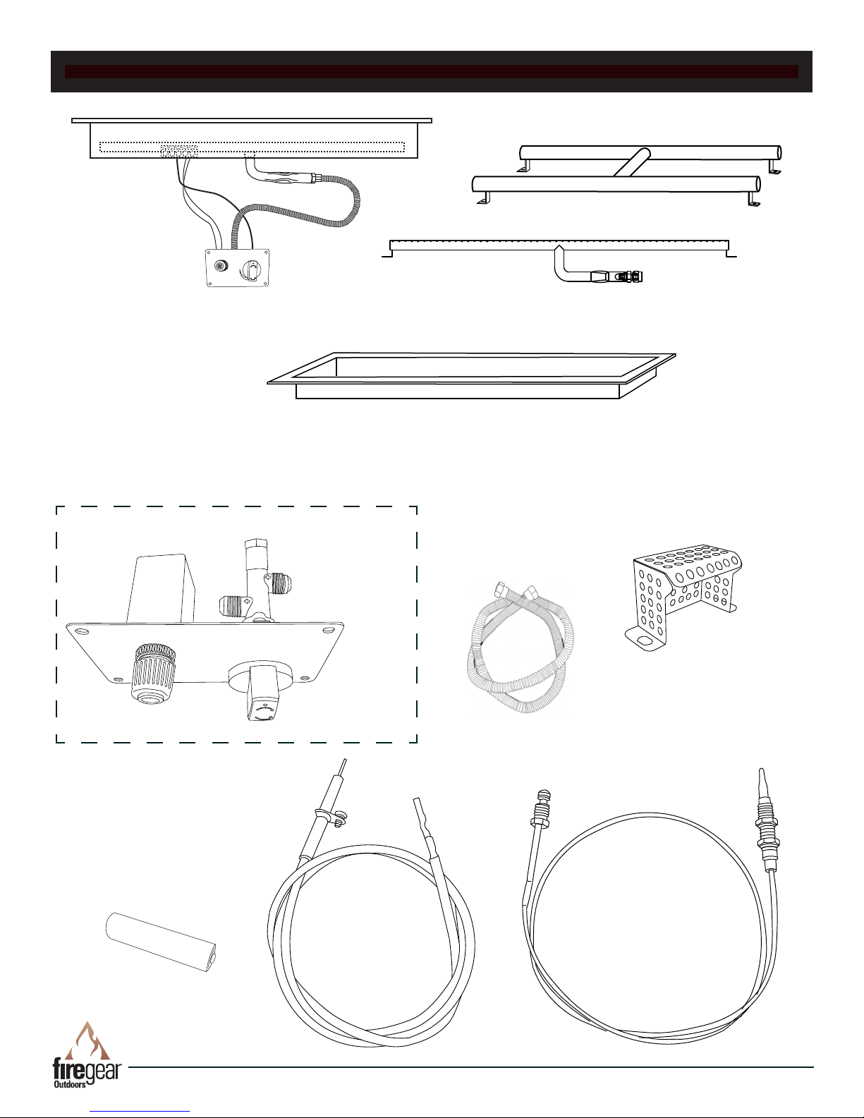
TMSI REPLACEMENT PARTS
O N
AA Battery
6
1
2
OFF
OFF
LOW
OFF
ON
3
7
9
10
11
8
5
O F F
4
Drawings not to scale.
13
12
Line of Fire - TMSI Series Fire Pits
REV. 1-8-18 Page 11

TMSI REPLACEMENT PARTS
Item
Description
Qty.
Part Number
1 30” Complete H-burner assembly 1 LOF-30LHTMSI-N
1 36” Complete H-burner assembly 1 LOF-36LHTMSI-N
1 30” Complete T-burner assembly 1
1 36” Complete T-burner assembly 1
LOF-30LTTMSI-N
LOF-36LTTMSI-N
2 30” H- Burner only 1 FG-H-30SS
2 36” H- Burner only 1 FG-H-36SS
2 30” T- Burner only 1 FG-T-30SS
2 36” T- Burner only 1 FG-T-36SS
3 30” H-Burner pan only (Refer to page 4 for specs) 1 PAN-SS3010L
3 36” H-Burner pan only (Refer to page 4 for specs) 1 PAN-SS3612L
3 30” T-Burner pan only (Refer to page 4 for specs) 1 PAN-SS3006L
3 36” T-Burner pan only (Refer to page 4 for specs) 1 PAN-SS3606L
4 Pilot Hood 1 FG-IGNITION-HOOD
5 Flex line (⅜” OD (¼” ID) with ⅜” are nuts) 22” long 1 T100-9898-22
6 Spark Ignitor Assembly (includes items # 6 & 12) 1 FG-SPARK-IGN
7 Manual gas valve 1 FG-GASVALVE-1
8 Gas control knob only 1 FG-CONTROL-KNOB
9 Control panel plate only 1 FG-CONTROL-FP
10 Control panel (includes items # 6, 8, 9, 10,11, 12, 13) 1 FG-CONTROLPANEL
11 AA battery 1 BATTAA
12 Ignitor - Ignitor & wire 1 FG-IGNITORWIRE
13 Thermocouple only 1 FG-TC-1
14 LP Conversion kit for (for all 30” & 36” models) 1 LOF-BO-LP40
Firegear Outdoor glass media comes in 5 lb. bags, Lava Rock comes in
10 lb. bags or 50 lb. box and Lava Stones come in 50 lb. bags.
Model Firegear Glass
LOF-30LHTMSI-N 27 lbs. 17 lbs. 34 lbs.
LOF-36LHTMSI-N 40 lbs. 25 lbs. 48 lbs.
LOF-30LTTMSI-N 16 lbs 9 lbs. 17 lbs.
LOF-36LTTMSI-N 19 lbs. 11 lbs. 21 lbs.
The table above list the amount of media needed for each size re pit. Media should
be spread evenly in the burner pan not covering the pilot hood. Note: Glass media
should not be more than 1-inch above the burner tube.
Line of Fire - TMSI Series Fire Pits
MEDIA REQUIREMENTS
Firegear
Reective GRL
Lava Rock
Firegear
Lava Stones
REV. 1-8-18 Page 12

FIRE PIT MAINTENANCE
1. The re pit should be inspected and cleaned before initial use at least annually by a qualied eld service person.
2. Any component that is found faulty must be replaced with an approved component.
3. Any tampering or modifying with the re pit is dangerous and voids all warranties.
4. During winter months in cold climates and various seasons operation of the re pit may be affected by weather
conditions. It is recommended to use a cover/lid overtop of your re pit to protect it from humid/rainy weather
conditions when not in use. Heavy rains/downpours could affect the re pit operation if not covered; if this occurs
ensure you allow the re pit time to dry out before attempting to operate. NOTE: If a combustible type cover is used
over the re pit when not in use be sure to remove it before operation to prevent a severe safety hazard.
5. Over time stainless steel parts can discolor when heated, usually a golden or brown hue. This discoloration is normal
and does not affect the performance of the appliance.
TROUBLE SHOOTING
Symptom Remedy
Fire pit won’t light 1. Bleed gas line.
2. Ensure all gas supply lines are turned ON.
3. Ensure there is not too much media overtop of burner; it can inhibit gas from owing.
4. Check gas pressure.
5. Ensure thermocouple is correct height. Tip of thermocouple should be fully engulfed by ame
and (approximately 1 ⅜” [35mm] to 1 ¾” [45mm] from base of bracket).
6. Check thermocouple voltage. Minimum voltage to operate system is 12-14mV.
Low ame 1. Ensure the base media is at least 1-inch in diameter and top media is no more than 1-inch over
top of burner.
2. Ensure all shut-off valves and key valve is fully open (see page 9; Fig. 6).
3. Check gas pressure.
Water in my re pit 1. Excess dust/sand material from media may be blocking the weep holes to relieve water.
Remove all media and unplug weep holes. Clean or install new media free of dust and dirt.
2. Ensure re pit enclosure has proper drainage for water and proper ventilation to dry out.
OPTIONAL ACCESSORIES
The following accessories are available from your local Firegear dealer/distributor.
Each accessory comes with a separate installation manual. Read each instruction thoroughly before installing.
Model Description
LOF-BO-LP40 Propane conversion kit (main burner orice)
VENT-6X12SS (2) Stainless steel vents (Provides 18 sq. in. per vent)
E-STOP2-5H 2 ½ -Hour mechanical gas timer valve with emergency shut-off
E-STOP1-0H 1-Hour mechanical gas timer valve with emergency shut-off.
Line of Fire - TMSI Series Fire Pits
REV. 1-8-18 Page 13

LOF-BO-LP40 (Natural to LP Gas Conversion)
Air Shutter
Sleeve
This instruction will properly convert the re pit from Natural gas to Propane (LP) gas. Follow the steps below to proceed.
See Table 2 on page 5 for proper LP orice.
Step 6: After the main burner orice and brass tting is re-
Step 1: Shut OFF gas supply.
Step 2: Remove media from re pit.
Step 3: Carefully lift re pit out of the enclosure.
Step 4: Remove the ⅜” ex connector from the main
burner orice. See Fig. 1 for reference.
moved then slide the air shutter sleeve off the burner tube
and expose the hole for the LP gas (Figs. 3 & 4).
Fig. 3. Natural gas setting; air shutter sleeved installed.
Burner Orice
OFF
OFF
LOW
OFF
ON
Fig. 1 Shows main burner orice location.
Step 5: Remove the ared tting. Inside the end of the
ared tting is the main burner orice. Remove the burner
orice and replace it with the new LP orice for the correct
model re pit.
3/8” Flared Fitting
Main Burner Orice
#LOF-BO-LP40
Fig. 4 LP gas setting; air shutter sleeved removed.
Step 7: Install the main burner orice and brass tting
back into the burner tube.
Step 8: Reattach the 3/8” ex connector to the ared
tting.
Step 9: Reinstall media.
Step 10: Installation is complete. Reinstall the re pit into
the enclosure, turn ON the gas supply and conduct a leak
test before presuming normal use with the re pit.
Fig. 2 Shows main burner orice.
Note: No Teon tape or thread compound is required
when threading brass to brass ttings.
Line of Fire - TMSI Series Fire Pits
REV. 1-8-18 Page 14

LIMITED WARRANTY
Skytech Products Group (Firegear Outdoors) hereby warrants
to the end user that products will be free from material and
workmanship defects that prevent safe and correct operation of
the product. The warranty commences from date of sale to the
end user for the following period:
CONSUMER/NON-COMMERCIAL APPLICATIONS:
Stainless Steel Components 5 Years
Gas Valve, Spark Igniter & Electronic Parts 2 Years
Log Sets 3 Years
Glass Windshields 5 Years
Glass Media 1 Year
Controls 5 Years
AnF Enclosures 5 Years
Lava Rock and Lava Stones are not
covered by warranty
COMMERCIAL APPLICATIONS:
Stainless Steel Components 1 Year
Gas Valve, Spark Igniter & Electronic Parts 1 Year
Log Sets 1 Year
Glass Windshields 1 Year
Glass Media 1 Year
Controls 1 Year
AnF Enclosures 1 Year
Lava Rock and Lava Stones are not
covered by warranty
Travel, diagnostic cost, service labor to repair the defect and
freight charges on warranty parts to and from the factory will
be responsibility of the owner. We will not be responsible for
labor charges and/or damage incurred in installation, repair, and
replacement.
This Limited Warranty is voided if not assembled, installed
and operated as intended. This Limited Warranty does not
cover any defects due to accident, abuse, misuse, alteration,
misapplication, vandalism, improper installation or improper
maintenance or service, removal from the original location or reinstallation into another location, or failure to perform normal and
routine maintenance.
Damage due to severe weather conditions such as hail,
hurricanes, earthquakes, tornadoes, discoloration due to overheating, exposure to chemicals (including salt), either directly or
in the atmosphere, or very high humidity, is not covered by this
Limited Warranty.
There are no other express warranties except as set forth herein.
For consumer applications, any applicable implied warranties of
merchantability and tness are limited induration to the period
of coverage of this Limited Warranty. Some states do not allow
limitation on how long an implied warranty lasts, so this limitation
may not apply to you.
End User must provide a bill of sale, canceled check, or payment
record from the end user to verify purchase date and to establish
warranty period. This Limited Warranty shall be valid and limited
to the original purchaser only.
WARNING Any modication to the product will void the warranty.
This Limited Warranty shall be limited to the repair and/or
replacement of parts that have proven to be defective under
normal use and service. Before returning any parts, contact
our Technical Service Department for a Return Materials
Authorization (RMA) number. All warranty claims must be made
by the OEM / Distributor / Dealer account on behalf of the end
user. You may contact Technical Service at (855) 498-8324.
All approved returned defects must be conrmed by our
Technical Service Department. If the defect is conrmed and we
approve the claim, we will replace such parts without charge.
This warranty gives you specic legal rights, and you may also
have other rights, which vary from state to state.
Line of Fire - TMSI Series Fire Pits
For Commercial applications, the liability of Firegear Outdoors
is limited to the express terms of this warranty. We expressly
disclaim any and all implied warranties, including any warranties
of tness for a particular purpose or merchantability.
We are not liable for any special, indirect or consequential
damages. Our maximum liability is limited to the purchase
price of the purchased products. Some states do not allow the
exclusion or limitation of incidental or consequential damages, so
this limitation or exclusions may not apply to you.
We do not authorize any person or company to assume for it any
other obligation or liability in connection with the sale, installation,
use, removal, return, or replacement of its equipment; and no
such representations are binding.
REV. 1-8-18 Page 15

NOTES
Line of Fire - TMSI Series Fire Pits
REV. 1-8-18 Page 16

FOR TECHNICAL SERVICE, CALL:
(855) 498-8324
Firegear Outdoors
9230 Conservation Way
Fort Wayne, IN 46809
Sales Support: (888) 699-6167
WEB SITE: www.regearoutdoors.com
Line of Fire - TMSI Series Fire Pits
REV. 1-8-18 Page 17

Having problems getting the re pit to operate? Don’t leave the job site!
We want to help! Call 855.498.8324 for Technical Support
between the hours of 8:00AM to 5:00PM EST.
Text photos to 260.255.5750 or e-mail photos to support@skytechpg.com.
BEFORE YOU CALL WE WILL NEED THIS INFORMATION
1. Model Number: ___________________________
2. Serial Number: ___________________________
3. How long is the gas line run? Nat Gas ____ LP Gas ____
4. What size is gas line? _____
5. Inlet Gas Pressure: _____WC
Manifold Gas Pressure: _____ WC
6. What type of media are you using? __________________
7. Review the troubleshooting section in the installation manual.
8. What are the symptoms? Please be prepared to explain.
9. Be prepared to send photos to us when on the phone.
10. Found missing or damaged parts? Let us know ASAP or send photos.
Line of Fire - TMSI Series Fire Pits
REV. 1-8-18 Page 18
 Loading...