

Firefox OGF - 2.7/RT, OGF - 3.0/RT, OGF - 3.5/RT Installation & Operating Instructions Manual
Page 1
OGF - RT Series
OPEN GAS FIREBOX
INSTALLATION & OPERATING INSTRUCTIONS
MODELS:
OGF - 2.7/RT
OGF - 3.0/RT
OGF - 3.5/RT
FIREFOX INDUSTRIES PTY LTD
ACN 074 490 654
Factory 4, 15 Stud Road Bayswater, Victoria 3153 AUSTRALIA Ph: (03) 9720 9055 Fax: (03) 9720 9255
This appliance must be installed by
authorized personnel in accordance with
manufacturers instructions, gas fitting
regulations, AGA 601 code for installation
of gas burning appliances, electrical wiring
regulations and any other statutory
requirement. The guidelines here-in
have been tested and approved to
AS 4558/AG 108. AGA Approval No. 6386.
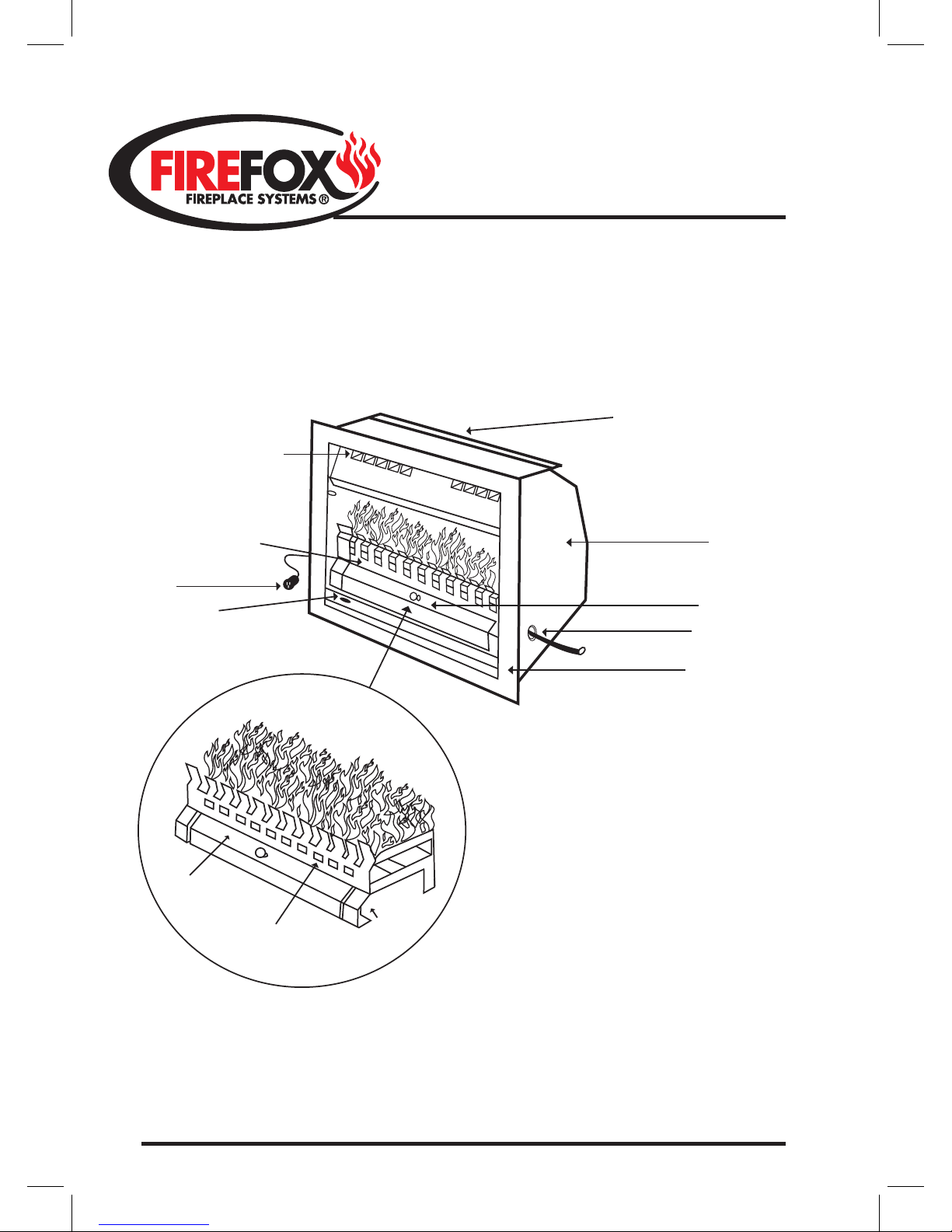
HOT AIR OUTLETS
EXHAUST OUTLET
INTO CHIMNEY
FIREFOX “OGF-RT”
FIREBOX
GAS FIREGRATE
CONTROL COVER PANEL
GAS INLET
COLD AIR INTAKE
FAN SWITCH
ELECTRIC
CORD
‘GFG’
For the appropriate Gas Firegrate ‘GFG’
to be used in conjunction with the Gas
Firebox (OGF). See specification pages
on the back of booklet.
G
A
S
E
N
T
R
Y
CONTROL
COVER PANEL
DECORATIVE FRONT IRON
Spec 20.1.11 FC
Page 2

OGF - RT Series
INSTALLATION REQUIREMENTS
DEFINITION
Installation of a Firefox OGF-RT series open fronted steel firebox into an existing fireplace chamber and
chimney which must be completely constructed of masonry and otherwise suitable for solid fuel burning
e.g. wood.
1. Check that the fireplace chamber and chimney is structurally sound.
2. Chimney dampers or baffles must be removed or permanently fixed open. The chimney must be free of
any obstructions which may cause a restriction in up-draught. It is mandatory that the fireplace has
sufficient up-draught in order to draw and exhaust combustion gases away and up the chimney.
3. Check that any air extraction devices located in the vicinity of the fireplace do not cause a
negative air pressure (suction) which could cause a spillage of combustion gases into the room where the
fireplace is located when in operation.
4. Permanent ventilation with a minimum cross sectional area of 40,000mm sq (64” sq) must be provided
into the room/area where the gas fire is located.
5. The fireplace chamber must be wide and deep enough to fully accommodate the Firefox steel firebox.
The masonry rollback at the rear of the existing fireplace chamber may be removed if extra depth is
required. The exhaust outlet at the top of the Firefox gas firebox must be free of obstruction so combustion
waste can exhaust freely up into the chimney and away.
6. GAS SUPPLY REQUIREMENT: Provide a 12mm (1/2”) copper gas pipe into the chamber with a tail
approx. ¾ of the way into the firebox. An access hole is provided on the right hand side of the unit 130mm
up from the base and 140mm in from the front of the unit. For MJ/HR rating of the gas firegrate burner
refer to specification pages.
7. ELECTRICAL SUPPLY: The firebox is supplied with 1.5m of lead and a 3 pin plug located on the lower
left hand side of the unit. The lead must not rise above 100mm of the base level of the firebox. If
connecting to a wall mounted isolating switch, ensure that the switch is far enough away so as to not
obstruct the fitting of a decorative surround i.e. mantelpiece.
8. Wrap the firebox with the insulation provided and slide the unit into the chamber. The firebox must be
completely sealed around the perimeter face of the existing fireplace opening.
9. Use only the appropriate Firefox gas firegrate/burner (GFG) in conjunction with the selected Firefox
OGF/RT firebox See GFG Series (GAS FIREGRATE) specifications, located in the following pages.
10. A gas cowl with a minimum diameter of 225mm approved AGA must be fitted to the top of the chimney.
For installation and commissioning procedure of the gas burner/firegrate (GFG) refer to separate details
entitled: INSTALLATION & OPERATING INSTRUCTIONS ‘GFG’ Series GAS FIREGRATES.
1
Page 3
OGF - RT Series
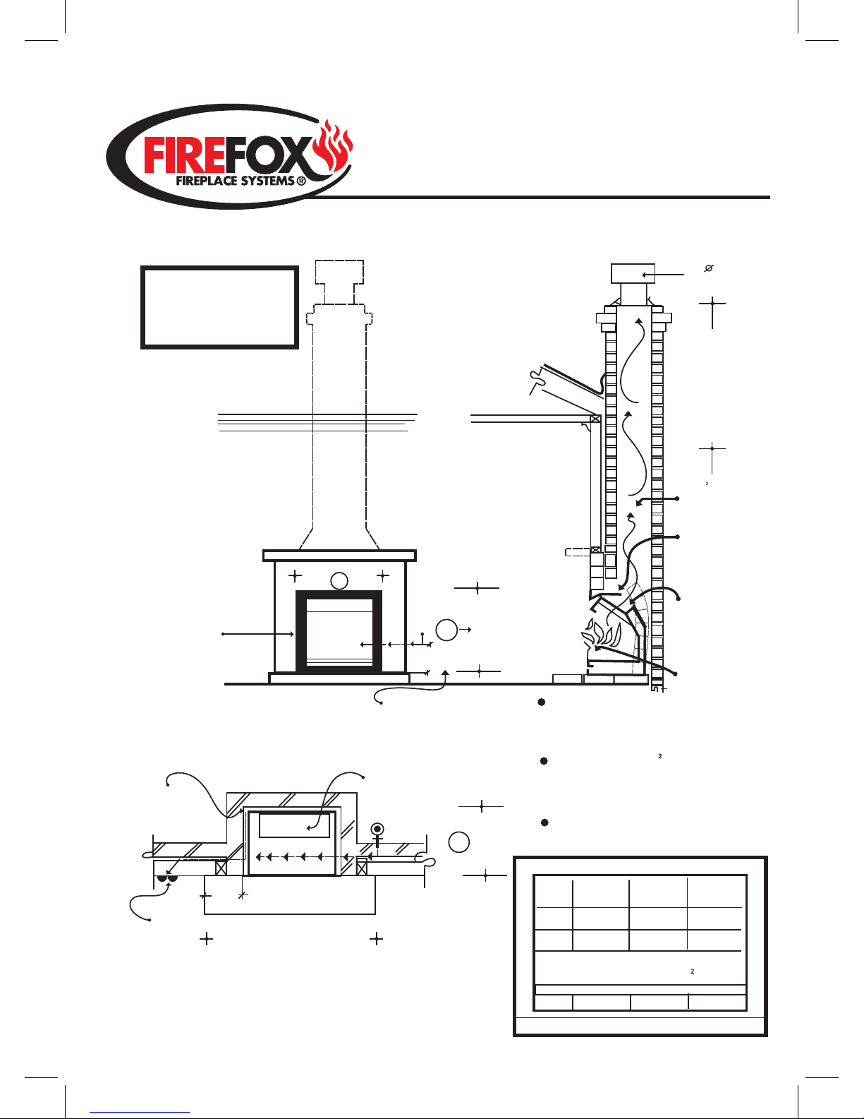
e.g. Open Gas Firebox into an Existing Masonry Fireplace & Chimney
6mm THK NON COMBUSTIBLE
FOREHEARTH & BASE UNDER
UNIT IF PLACING ON A
COMBUSTIBLE FLOOR
SECURE FIREBOX IN
POSITION & ENSURE
FACE EDGES OF UNIT
ARE SEALED TO
MASONRY
EXAMPLE ONLY
This detail must be read in
conjunction with manufacturers
Installation Requirements &
Operating Instructions.
NOTE: DO NOT LOCATE ANY
EXTRACTION AIR DEVICE WHICH
MAY CAUSE A NEGATIVE AIR PRESSURE
IN THE ROOM WHERE
THE GAS FIRE IS LOCATED
PLUMBING & ELECTRICAL MUST BE
CARRIED OUT BY AN AUTHORISED
PERSON
OGF - 35-RT
52
MIN. WIDTH
A
C
B
115
GAS ENT
RY
MIN. HEIGHT
R
/
L
I
N
E
225
GAS COWL
600 MIN.
ABOVE R/LINE
(3600 MIN. FROM
TOP OF UNIT)
400cm MIN.
CROSS SECTION FLUE
EXHAUST AREA
EXISTING MASONRY
ROLL BACK CAN
BE REMOVED TO
ACCOMMODATE
FIREFOX UNIT
ENSURE THAT
EXHAUST OUTLET
AT TOP OF UNIT
IS UNOBSTRUCTED
INTO CHIMNEY
FIREFOX GAS
FIREGRATE (’GFG’)
WRAP
INSULATION
BLANKET
AROUND UNIT
DO NOT
OBSTRUCT
EXHAUST
OUTLET
GAS ENTRY
INPUT
DEPTH
MIN.
FOREHEARTH VARIABLE
ELEC
SUPPLY
SWITCH
200
MIN
FOREH EARTH
VENTILATION OF 400cm IS
REQUIRED INTO THE ROOM
WHERE THE GAS FIRE IS LOCATED,
e.g. ROOF/CEILING SPACE OUTSIDE
WALL CAVITY OR SUB-FLR. AREA
DIMENSIONAL REQUIREMENTS
MODEL
OGF - 27-RT
OGF - 30-RT
A
B
C
650
590
385
710
590
385
830
590
385
Mj/hr 36 42
GAS INPUT REQUIREMENTS
MINIMUM CROSS SECTION AREA OF
CHIMNEY FLUE REQ 400cm
CHECKDATA PLATE ON ‘GFG’ FOR CORRECT GAS TYPE
2
Page 4
OGF - RT Series
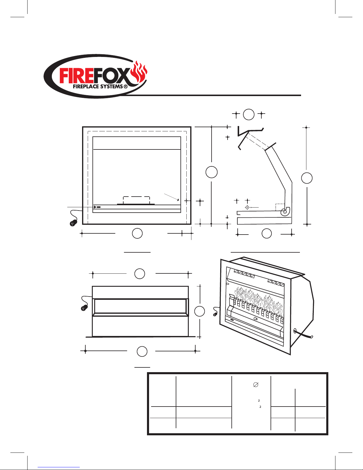
OPEN GAS FIREBOX SPECIFICATIONS
FRONT
TOP
RIGHT HAND SIDE
A
A
F
C
D
B
E
FAN
FAN
FAN
SWITCH
POWER
SUPPLY
EXHAUST OUTLET
POWER
SUPPLY
GAS PIPE
INLET
GAS PIPE
INLET
C
30
140
75
75
FIREBOX
MODEL
OGF - 27/RT
400cm
(64inch)
CROSS SECTION
EXHAUST AREA
OGF - 30/RT
OGF - 35/RT
FIREBOX DIMENSIONS
A B C D E F
720 640 370 210 620 590
780 640 370 210 680 590
900 640 370 210 800 590
}
}
}
CHIMNEY
FLUE
}
}
}
APPROPRIATE GAS
FIREGRATE‘GFG’
GFG 2.7
GFG 3.0
GFG 3.5
115
For installation and
commisioning procedure of
the Gas Firegrate/Burner
‘GFG’ refer to seperate
instructions entitled;
INSTALLATION & OPERATING
INSTRUCTIONS ‘GFG’ Series
FIREGRATES.
GAS INPUT
NG LP
36 - 35 Mj Hr
41 - 40 Mj Hr
52 - 50 Mj Hr
3
Page 5
OGF - RT Series
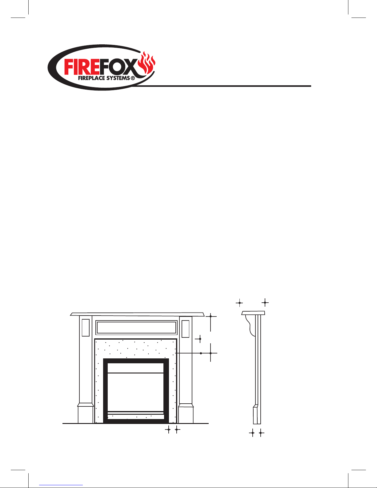
CLEARANCE TO COMBUSTIBLE DECORATIVE SURROUNDS
Decorative surrounds i.e. timber
mantelpieces/combustible moulding must be
50mm (min) clear of the face side edges and top
face edge of the firebox.
Upright legs and breast sections of
combustible surrounds must not project further
than 50mm (max) forward of the face of the firebox.
Mantle shelves must be 300mm (min)
clear above the top edge of the firebox and must
not project more than 250mm (max) forward of
the face of the firebox.
A non-combustible floor protector
(forehearth) at the base directly in front of the
firebox opening must be a minimum of 6mm
thick, project a minimum 300mm forward and
200mm on each side of the firebox opening.
MANTLEPIECE BREAST
G
E
L
0
5
N
I
M
50
MIN
50
MAX
250
MAX
0
0
3
N
I
M
FIREFOX
OGF UNIT
4
Page 6
OGF - RT Series
USER INSTRUCTIONS
Congratulations on having a FIREFOX
fan forced gas log fire installed in your
home. We are sure it will provide you with many
years of realistic fireside pleasure, comfort and
enjoyment.
It is important that you familiarize
yourself with the appliance by reading through
these instructions.
If your installer has not shown you how
to light the FIREFOX gas firegrate which has
been fitted into the unit, refer to the separate
booklet entitled INSTALLATION & OPERATING
INSTRUCTIONS - GFG SERIES (Gas Firegrates
-L/C effect) under Lighting Burner &
Commissioning and also familiarize yourself with
the USER INSTRUCTIONS contained there-in.
Your FIREFOX gas firebox incorporates
a sophisticated heat exchanger design which
collects heat and a 2 speed fan which transfers
the collected heat into the room/area where the
FIREFOX is located. The fan control switch is
located on the lower left hand front of the unit.
The fan can remain OFF whilist the gas firegate
is in operation. To boost heat output simply
select one of the two fan speeds avaliable i.e.
LOW or HIGH.
Your FIREFOX gas unit is relatively
maintenance free. However we recommend that
you have the appliance/installation checked once
a year to ensure correct operation.
SAFETY PRECAUTIONS
As with any live naked flame burning
apparatus, it is important in order to protect
against personal injury or property damage to
treat its operation with care and respect. A
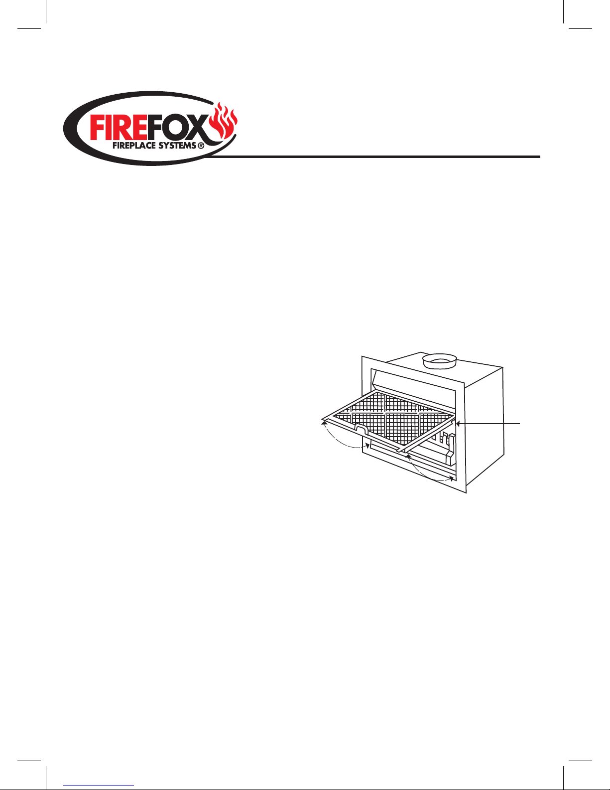
safety screen/fireguard should be used for the
protection of children, elderly and infirm.
WARNING
DO NOT PLACE FOREIGN ARTICLES ON OR
AGAINST THE APPLIANCE.
DO NOT USE OR STORE FLAMMABLE
MATERIALS NEAR THE APPLIANCE.
DO NOT SPRAY AEROSOLS IN THE VICINITY
OF THE APPLIANCE WHILST IN OPERATION.
DO NOT USE GAS LOGS/COALS BURNERS
OTHER THAN THAT SPECIFIED FOR THE
APPLIANCE.
MAGNETIC TABS
SCREEN
LOCATING PINS
5
 Loading...