

Firefly YASBP-56HL, YASBP-25HL, YASBP-38HL, YASBP-90HL User Manual, Installation & Operation
Page 1

Air Source Heat Pump
Applicable Models: YASBP-25HL
YASBP-38HL
YASBP-56HL
YASBP-90HL
Jan. 2012s V
Presented b y Ji mm y Zh an g
Than k yo u ve ry much f or p ur chasi ng o ur a ir sour ce h ea t pumps .
Plea se r ead this ma nu al c arefu ll y an d keep it f or f ut ure ref er en ce befo re i ns talling a nd u sing the he at p umps.
Page 2

Hot Water S eri es
CONTENTS
9. Maintenance and Trouble Shooting
9.1 Maintenance
9.2 Parameter Checking
9.3 Error Code
9.4 Trouble Shooting
7. Controller Operation
7.1 Keys Illustration
7.2 Illustration for LCD Display
7.3 Water Temperature Setting
7.4 Clock Setting
7.5 ON/OFF Time Setting
6. Commissioning
6.1 Preparation Before Commissioning
6.2 Commissioning
5. Installation
5.1 Heat Pump unit Installation
5.2 Water System Installation
5.2.1 Water Tank Installation
5.2.2 Water Piping Installation
5.3 Power Source Installation
4. Technical Data
4.1 Parameter Table
4.2 Dimension
4.3 Performance Curves
4.4 System Diagram
4.5 Components
1. Features/Benefits
2. Notes/Precautions
3. Model Number Nomenclature
8. Circuit Drawing
1
1
2
2
2
3
4
8
9
10
10
11
11
11
12
14
14
14
15
15
16
16
18
19
21
23
23
24
24
25
5.4 Wire Controller Installation
13
Page 3

1. Features/Benefits
Wide App lication Ran ges
Full Consi deration for Nois e Control
The Thermal Mas ter S eries is designed for
Compressor ru bbe r feet are specially select ed for
domestic hot wa ter f or a houses, as well as small
reducing vibr ati on. Specially, co mpressor sound
commercial bu ild ings such as small hotels, jacket is avail able for every unit. Well- balanced
offices, scho ols , hospitals, apartme nts e tc. The fans and fan moto rs, w ith the optimized fan
holder, contributes to the l ow no ise operation. The
hot water outle t ran ge is wide from 20 to 60 ,
cabinet insid e is insulated to reduce noise
meeting deman ds fo r most hot water project. The
transmissio n.
performance i s at wi de ambient temperature
range from -10~ 43 . Modular control system i s
Relia ble D esign and Strict Qu ality Control
available to me et th e demand of bigger hot water
Standard safe ty fe atures for the refrigeran t circuit
projects.
include high- pre ssure switch and low-pres sure
Assur ing You Get Gra nts from Governme nt
switch to detec t los s of refrigerant, as well as
Designed for hi gh ef ficiency performance ov er a
deficient wat er fl ow. Equipment safety feat ures
lifetime of ope rat ion. The annual average COP i s
include water l oop t emperature monitoring ,
up to 4.5. The wate r pip es and refrigerant pipes
voltage prote cti on, water coil freeze prote ction.
are well insula ted t o minimize the heat loss.
All safety feat ure s are tested and run at the facto ry
to assure prope r ope ration of all components an d
Durab le an d Long Life
safety switch es.
High efficien cy co mpressor for all units , wit h
All component s are c arefully designed and
durable featu res a gainst high temperature a nd
selected for en dur ance, durability, and carefree
high pressure f or lo ng life. The tube in shell heat
day-to-day operation. Ea ch un it is fully tested in
exchanger are d ura ble for anti-corrsion, ha rd
performance a nd sa fety before exit factory.
water, high pressure and une xpe cted freeze
caused by power c ut-off.
Simple Mai ntenance and Serv iceability
Full acce ss fo r maintenance or service is p rovided
Strong Cab inet
from the mainte nan ce panel, for better flexib ility in
Standard unit f abr ication consists of heavy g age
confined spac e. Ea sy removal of the control box
galvanized sh eet m etal cabinet constructi on th at
from the unit pro vid es access to all refrigeran t
provides maxi mum s trength. All interior she et
components. T he re frigerant circuit is easi ly
metal surface s are p owder-painted for maximum
tested and serv ice d though the use of high and
corrosion pro tec tion to ensure resilience f or long
low pressure po rts i ntegral to the refrigeran t
term vitality. Compact, stackable c abinets are
circuit.
designed to min imi ze installation spac e.
° °
C C
°
C
Hot Water S eri es
1
The installat ion , commissioning and wires are apart f rom h ot or moving parts [eg:
maintenance o f the s ystem should only be done compressor, f an] o f the system to avoid
by qualified pe rsonnel with adequate knowle dge damage to the wir es.
of the relevant s tan dards and local regulatio ns as
Anti-freezi ng me asures must be well done to
well as experie nce w ith similar systems.
avoid damage to t he wa ter system and the heat
pump water heat e xch anger.
Please make sur e the w ater flow is sufficient all
the time.
Please make sur e the l ifting and transportati on
are safely done a cco rding to the heat pump
All ground line c onn ections must be prepared in
size and weight .
accordance wi th re levant local regulation s.
It is very danger ous w ork done at the facility
To reduce the risk of electrical i nsulation faults,
without previ ous ly cutting off the electric ity from
you first make th e con nection of the protective
the main power so urc e.
conductor of th e hea t pump safe according to
local regulat ion s.
When installi ng th e system, please ensure tha t
no contaminan ts en ter the water cycle.
When installa tio n, mak e sure that the inside
2. Notes/Precautions
■
■
■
■
■
■
■
■
■
Page 4

Hot Water S eri es
3. Model Number Nomenclature
Y ASBP - 25 HL
HL - Si ngle Phase; H S - 3 Phase s
25 - 1HP 38 - 1. 5HP 56 - 2HP 90 - 2.5HP
AS BP - Horizontal Fan; Y ASA - Ver tical Fan
FIREFLY
Po wer Supply
Case St ruc ture
Co mpany
Input Power
Running Current
Max. Input Power
Max. Running Current
Refrigerant
Compressor
Compressor Type
Compressor Quantity
Outlet Water Temp
Max. Outlet Water Temp
Hot Water Output
Water Flow
Condenser
Water Pressure Drop
Water Connection Tube
Noise
Electric Protection
Mechanical Protection
Power Supply
Heating Capacity
Net/Gross Weight
Dimension
Packing Dimension
3.91
0.8
3.64
1.2
5.57
R410a
Panasonic
Rotary
1
55
60
86
0.8
Tube in shell
20
3/4"
<48
I
IPX4
220/1/50
YA SBP-2 5HL
38/43
770/300/490
820/325/520
kW
kW
A
kW
A
ºC
ºC
L/h
3
m /h
Kpa
mm
dB(A)
V/Ph/Hz
kg
mm
mm
5.1
1.214
5.31
1.7
7.75
R410a
Panasonic
Rotary
1
55
60
110
1.1
Tube in shell
20
<48
I
IPX4
220/1/50
YA SBP-3 8HL
51/56
940/360/550
985/390/590
3/4"
7.53
1.88
8.7
2.23
10.32
165
1.6
20
<48
220/1/50
YA SBP-5 6HL
58/63
940/360/550
985/390/590
R410a
Rotary
1
55
60
Panasonic
Tube in shell
3/4"
I
IPX4
Measu ring cond ition: Dry/wet bu lb te mp 20ºC/ 15ºC; Water outle t temp 15 ºC~55ºC.
4. Technical Data
4. 1 Parameter Table
2
Mo dle Typ e
9.05
2.61
11.86
3.99
18.12
210
2.1
20
<48
220/1/50
YA SBP-9 0HL
65/70
1010/370/615
1140/400/670
R410a
Rotary
1
55
60
Panasonic
Tube in shell
3/4"
I
IPX4
Page 5
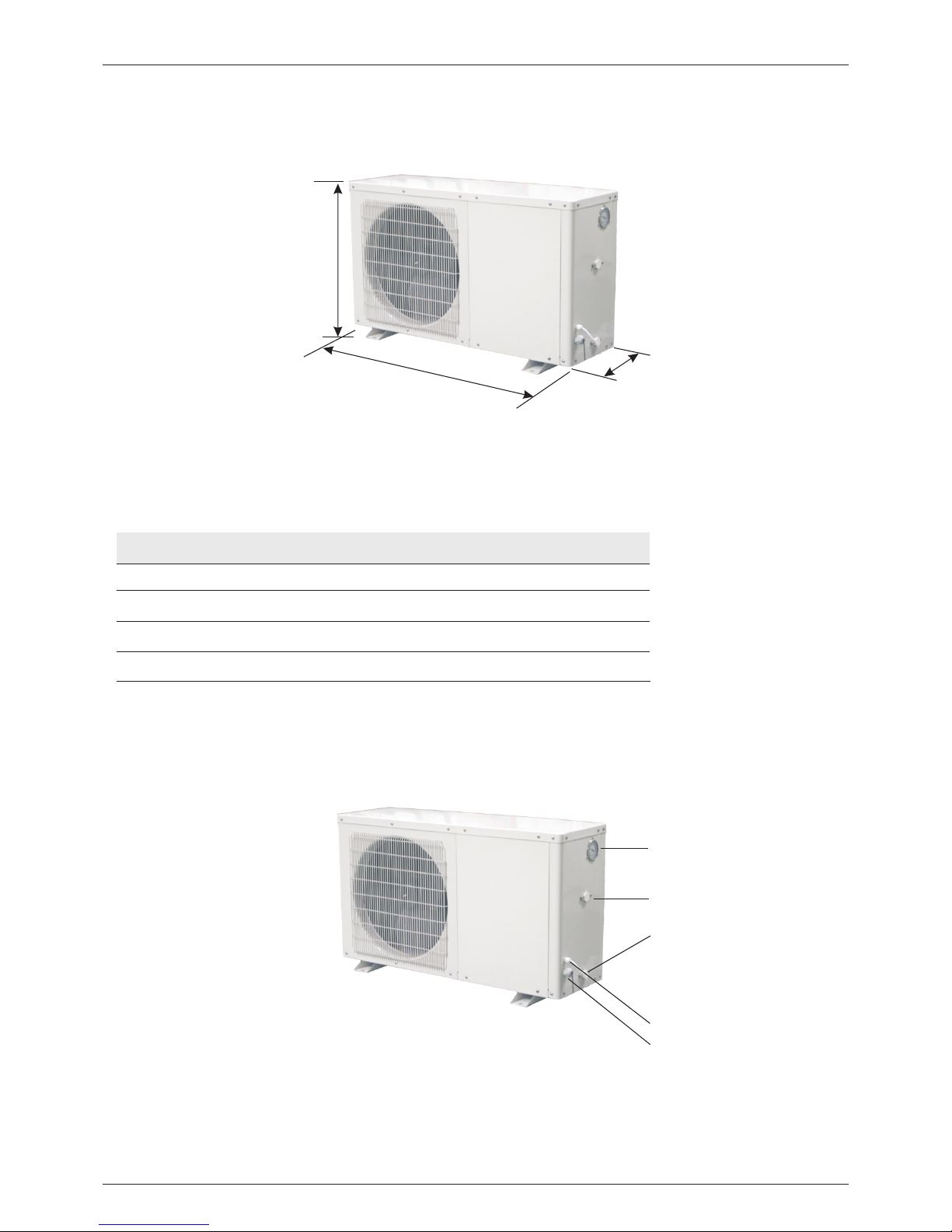
Water Outl et
Water Inle t
Power Su pp ly Cabl e Hole
Cont roller Ca ble Hol e
Hot Water S eri es
770
940
Length (mm)
300
360
Wide (mm)
490
550
Height (mm)
YASBP-25HL
YASBP-38HL
Model
4. 2 Dimension
3
L
H
W
High P ressu re G auge
940 360
550
YASBP-56HL
1010 370
615
YASBP-90HL
Page 6
Hot Water S eri es
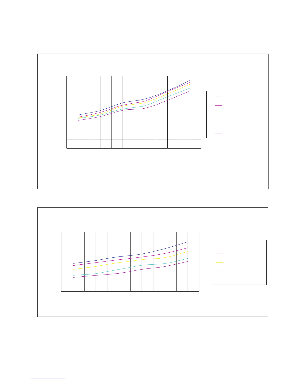
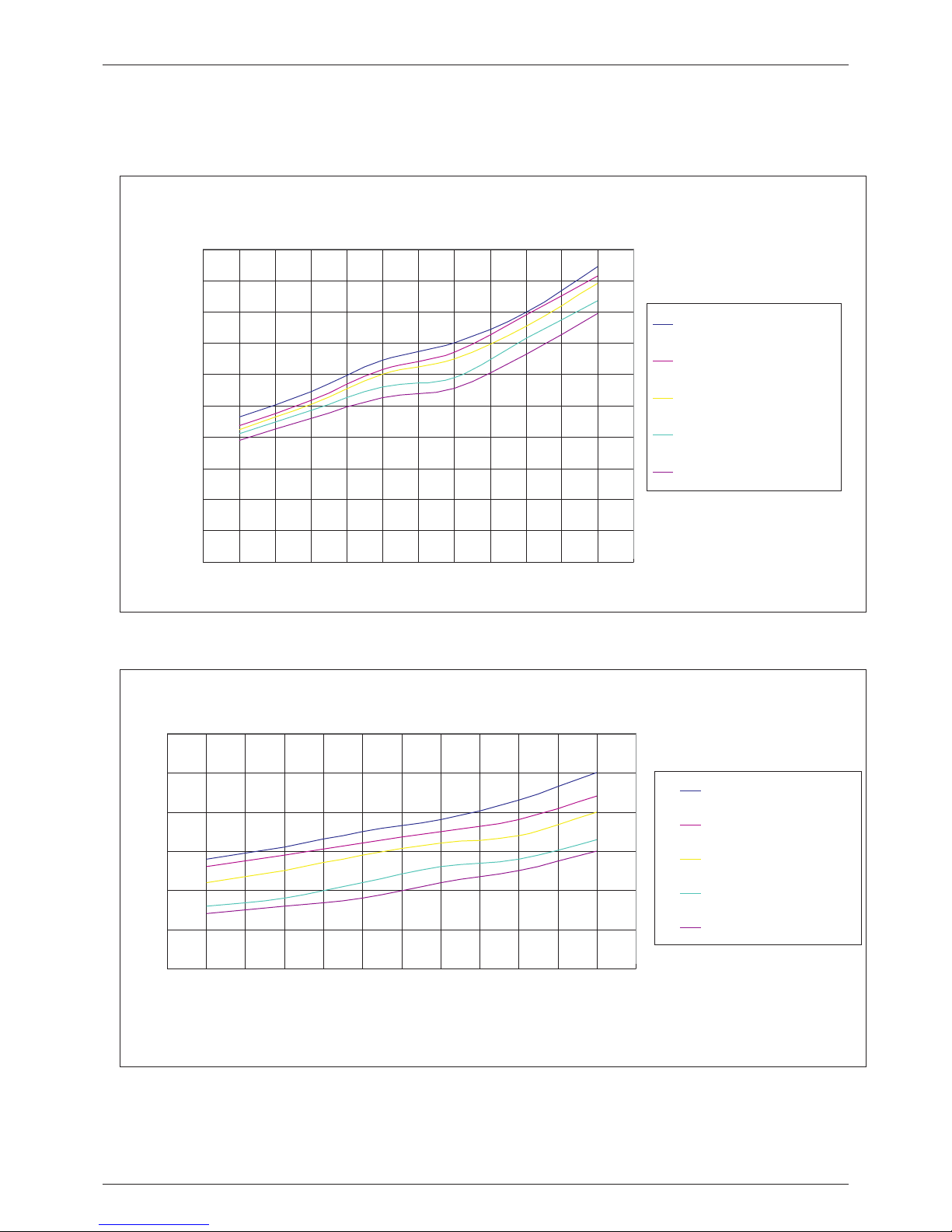
4.3 Performance Curves
Model: YASBP-25HL
4
KRS-35B/N2-S Heating Capacity Curves
0
500
1000
1500
2000
2500
3000
3500
4000
-10 -5 0 5 10 20
Ambient Temp. (℃)
Heating C apacity (W)
R eturn Water Temp.30
℃
R eturn Water Temp.35
℃
R eturn Water Temp.40
℃
R eturn Water Temp.50
℃
R eturn Water Temp.55
℃
YASB P-2 5HL Heati ng Ca pacit y
He
at
ing C
a
pa
cit
y (
W)
Ambi ent Temp . (℃)
COP Curves
0
1
2
3
4
5
6
-10 -5 0 5 10 20
Ambient Temp. (℃)
COP
Return Water Temp.30
℃
Return Water Temp.35
℃
Return Water Temp 40
℃
Return Water Temp.50
℃
Return Water Temp.55
℃
YASBP-25HL COP Curve
CO
P
Ambi ent Temp . (℃)
Page 7
Hot Water S eri es
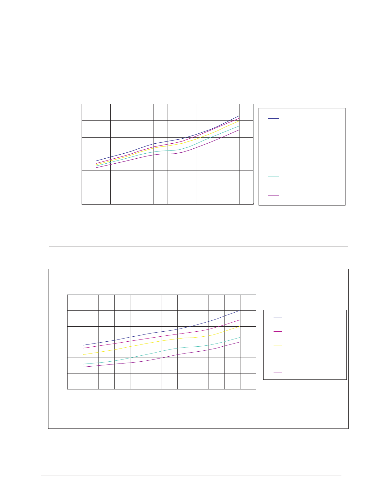
Model: YASBP-38HL
5
C OP C urves
0
1
2
3
4
5
6
-1 0 -5 0 5 10 2 0
Ambient Temp. (℃ )
COP
R eturn W a te r T e m p .3 0 ℃
R eturn W a te r T e m p .3 5 ℃
R eturn W a te r T e m p .4 0 ℃
R eturn W a te r T e m p .5 0 ℃
R eturn W a te r T e m p .5 5 ℃
YASBP-38HL COP Curve
C
O
P
Ambi ent Temp . (℃)
KRS-50B/N2-S Heating Capacity
0
1000
2000
3000
4000
5000
6000
-10 -5 0 5 10 20
Ambient Temp. (℃)
Heating C apacity(W)
Return Water Temp.30
℃
Return Water Temp.35
℃
Return Water Temp.40
℃
Return Water Temp.50
℃
Return Water Temp.55
℃
YASB P-3 8HL Heati ng Ca pacit y
He
at
i
ng Ca
pa
c
i
t
y (
W
)
Ambi ent Temp . ( )℃
Page 8
Hot Water S eri es
6
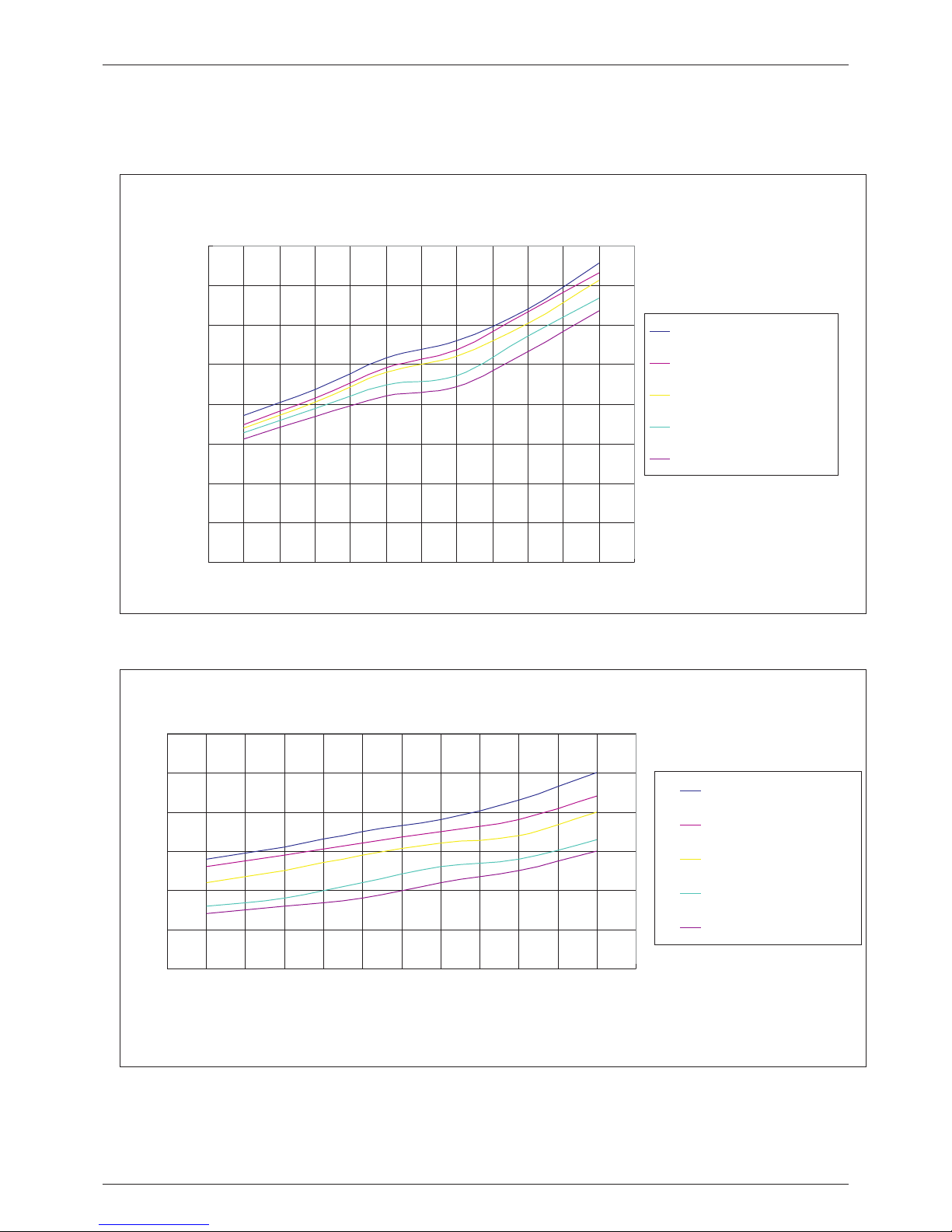
Model: YASBP-56HL
KR S -72 B /N2 -S Hea ting C a pac ity
0
1 0 0 0
2 0 0 0
3 0 0 0
4 0 0 0
5 0 0 0
6 0 0 0
7 0 0 0
8 0 0 0
-1 0 - 5 0 5 1 0 2 0
Am b ie nt T em p. (℃ )
HeatingCapacity(W)
R e tu r n W a te r T e m p .3 0
℃
R e tu r n W a te r T e m p .3 5
℃
R e tu r n W a te r T e m p .4 0
℃
R e tu r n W a te r T e m p .5 0
℃
R e tu r n W a te r T e m p .5 5
℃
YASB P-5 6HL Heati ng Ca pacit y
He
atin g Ca
p
a
cit
y (
W
)
Ambi ent Temp . (℃)
C OP C urves
0
1
2
3
4
5
6
-1 0 -5 0 5 10 2 0
Ambient Temp. (℃ )
COP
R eturn W a te r T e m p .3 0 ℃
R eturn W a te r T e m p .3 5 ℃
R eturn W a te r T e m p .4 0 ℃
R eturn W a te r T e m p .5 0 ℃
R eturn W a te r T e m p .5 5 ℃
YASB P-5 6HL COP Curve
C
OP
Ambi ent Temp . (℃)
Page 9
Hot Water S eri es
7
Model: YASBP-90HL
Ambi ent Temp . (℃)
KR S -90B/N2-S Heating Capacity
0
10 00
20 00
30 00
40 00
50 00
60 00
70 00
80 00
90 00
10 000
-10 -5 0 5 10 20
Ambient Temp. (℃ )
HeatingCapacity(W)
R e turn W ate r T e m p.30
℃
R e turn W ate r T e m p.35
℃
R e turn W ate r T e m p.40
℃
R e turn W ate r T e m p.50
℃
R e turn W ate r T e m p.55
℃
YASB P-9 0HL Heati ng Ca pacit y
H
e
a
t
i
ng C
a
pac
i
ty (W
)
C OP C urves
0
1
2
3
4
5
6
-1 0 -5 0 5 10 2 0
Ambient Temp. (℃ )
COP
R eturn W a te r T e m p .3 0 ℃
R eturn W a te r T e m p .3 5 ℃
R eturn W a te r T e m p .4 0 ℃
R eturn W a te r T e m p .5 0 ℃
R eturn W a te r T e m p .5 5 ℃
YASB P-9 0HL COP Curve
C
O
P
Ambi ent Temp . (℃)
Page 10

Hot Water S eri es
4.4 System Diagram
Heating Mode
Water inl et
Water inl et
Water out let
Water out let
Defrosting Mode
High pressure switch
High pressure switch
Low pressure switch
Low pressure switch
4 way valve
4 way valve
Suction accumulator
Suction accumulator
Compressor
Compressor
Condenser
(fin-tube)
(fin-tube)
Evaporator
Throttling
element
Evaporator
(Tub e in shell)
Condenser
(Tub e in shell)
8
Throttling
element
Page 11

Hot Water S eri es
4.5 Components
Compressor
The dependable hig h eff ici ency
compressor, with optimized
R410a system, can achie ve hi gh
water temperature up to 6 0De gC,
while ensures long l ife o f the
compressor.
4-Way valve
The reliable 4 wa y val ve can
avoid gas mixin g, and ensure
stable defros ting.
Condenser
The Tube in shell heat exchanger as
condenser, with bigger hea t
exchanging ar ea an d higher
efficiency.
Evaporator
The hydrophil ic fi n-tube heat
exchanger has b ig he at exchanging
area and ration al fi n distance, thus
significant ly improves heating and
defrosting ef ficiency.
Fan
The exterior mo tor f an, with multiple fan
blades, is stri ctly balanced. The multiple
fan blades run sl owe r, and mak e sur e
high air volume , thu s largely brings down
the noise.
Photo Features/AdvantagesComponents
Circulation pump
Fa mous German brand WI LO
ci rculation water pu mp used .
The main compon ent s are of famous brands and with g ood quality tested.
For examp le: Panasonic compressor, R410A gas, hig h eff iciency tube-in-shell h eat e xchanger etc.
Also, compone nts c an be replaced by customer’ s own r equirement.
9
Page 12

Hot Water S eri es
5. Installation
5.1 Heat Pump Installation
10
Se lect ion of i nsta llat ion si te
1. Installation must be simple and allow easy access for later work.
2. If the unit is to be installed on the floor, its undercarriage should be heightened, to avoid
ingression of acculated water in rainy season. In snowy areas, it is important to prevent
accumulated snow from blocking up the air-out.The recommended height is 20cm to 30cm.
3. Drain ditch or other facilities should be arranged under the outdoor unit, to avoid the
environment influence because of water discharge.
4. To install the unit at balcon or top of building, the installation site must meet the
Allowable bearing capacity of building structure, without affecting the structural safety.
5. Ensure the unit is well ventilated, direction of air exhaust is kept away from windows of
neighboring buildings, and the exhaust air cannot flow back. Moreover, adequate service
clearance should be kept around the unit.
6. The unit sould not be installed at places accompanied with oil, Inflammable gas, corrosive
compents, e.g. Sulfur compound, or high-frequency equipment.
7. The unit must be installed on reliable base or framework. Weight capacity of framework
should be 3 times of the body weight, and safeguard measures should be taken to avoid
malfunction of fastenings.
8. The unit should not be installed at sites with typhoon/earthquake hazards. Midair
installation should be avoided as much as possible as machine falling down may result in
Severe accident.
9. Do not install the heat pump close to a road or path to avoid mud splashing on the unit.
10. Keep, wherever possible, the unit out of reach of children.
Installation in some exceptional circumstances (mm):
3 5 0
2 0 0
3 5 0
4 0 0
3 5 0
3 5 0
2 0 0
No obstacl e in front of the heat pu mp Ob stacle above the he at pump
Sever al he at pumps insta lle d in a row
Page 13

Hot Water S eri es
5.2 Water System Installation
5.2.1 Water Tank Installation
5.2.2 Water Piping Installation
1. The water tank s hou ld be put in a place where suggeste d to in stall the heat pump, the wate r
ambient tempe rat ure is more higher. tank and the ci rcu lation pump at the same level .
Besides, the he igh t difference between the he at
2. It can be instal led e ither outdoors or on the
pump and the wate r tan k should be no more than
roof-to p (some elements such as the si ze of
2 meters, when wa ter t ank position is higher than
water tank and th e bea ring capability of the
that of the heat pu mp.
building shou ld be considered). Instal lat ion on
roof-to p should be based on suppo rt su ch as 4. Do not install t he wa ter tank in a pollutive or
crossbeam or pi lla r. corrosive are a.
3.The water tan k sho uld not be installed lower
than the founda tio n of the heat pump; It is
1. Drainpi pe an d overflow pipe should be carried out for t he wa ter supply valve and the
installed nea r the g utter or the sinkhole for stop valve of the s yst em (according to local
draining wate r mor e efficiently. Di scharge valve ambient temperatu re) f or avoiding icing of the
is necessary on t he dr ainpipe. water supply pi pe an d the valves.
2. Service valv e needs to be installed befor e the 6. Keep the water pipes straigh t and t he pipeline
magnet-valves on the sy ste m pipeline for further allocation rea son able; Reduce pipe turning s as
inspection. many as possibl e to reduce water resistance.
3. The pressure o f the water outlet should be 7. Prevent the pi peline and the connectors from
between 0.3MPa an d 0.6MPa. water leakage .
4. It is recommen ded to use metal pipeline suc h 8. The water p res sure bearing capability o f each
as stainless st eel p ipes, internal-pla sti c pipes, part of the pipin g system should be tested after
internal stai nle ss steel pipes or copper pipe s the installatio n is fi nished; Drainage should b e
etc; Telescopic issue of the pip eline between done to create a cl ean i nterior system.
heat pump unit an d wat er tank should be
9. Measures of he at preservation for the hot
considered if p lastic pipeline such as PPR p ipe
water pipelin e nee d to be conducted after
and ABS pipe etc. is used.
assuring no wat er le akage.
5. In winter, heat preservat ion may need to be
11
Wate r
Tan k
Wate r
Tan k
Page 14

Hot Water S eri es
Heat pump Installation
Shut Off Valve
Solenoid Valve
Check Valve
Elec Heater
Water Pump
Y-Shape Filter
12
Flow Switch
Heat Pump
Controller
Heat Pump
Dinning Hall
Filter
Filter
Flow Switch
(can omit)
Guest Room
Sauna Room
Drainage
Water Tank
Check Valve
Water tank
temp. sensor
5.3 Power Source Installation
Recommended w ire s pecification
2
3x1.5mm
Po wer Cable
LC D controller
Se nsorMo del Wa ter Pump
YA SBP-25HL
YA SBP-38HL
YA SBP-56HL
2
3x1.5mm
2
3x2.5mm
2
3x0.75mm
2
3x0.75mm
2
3x0.75mm
2
3x0.35mm
2
3x0.35mm
2
3x0.35mm
2
2x0.35mm
2
2x0.35mm
2
2x0.35mm
NOTE: the ab ove s pecification is the lowes t one w e recommend. Please choos e bigger wires if additiona l
power is requir ed un der installation.
YA SBP-90HL
2
3x2.5mm
2
3x0.75mm
2
3x0.35mm
2
2x0.35mm
NOTE:
Before instal lin g the heat pump unit, please re ad this manual carefully and kee p it for future reference.
Page 15

M
SE
T
M
SET
5.4 Wire Controller Installation
The wired controller is originally fixed on the maintenance door of the mac hine; please refer t o bel ow
steps if you want t o ins tall it on the wall:
1.Take do wn the controller from the ma chi ne. Pleas e pay attention that th e communi cat ion wire is
connected wit h the c ircuit board, separate th em fr om where they match.
2.Use a scre wdr iver to open the clip as pictur e 1, separate the controller as 2 pa rts, as picture 2
3.On the w all that you are going to install th e controller, drill 2 hole s at a level para lle l to the sight li ne as
picture 3.
The hole distan ce is 6 0mm, diameter is 8mm.
4.Place the plastic screws of th e enclos ure into the hole, and use the tapping screw (ST4*16 D- 1)
enclosed to fix t he ba ck cover of controller on the w all , as picture 4.
5.Match th e fro nt and back covers perfectl y, as picture 5, make sure t hat it is fixed firmly on the wal l.
6.Connec t the c ommunication wire well.
1 2
5
6
The front cover
6
0
mm
Φ8
3 4
Outl et of the comm unicatio n wire
Attention :
Please don't use ke en-edged things to hit the contro ller face and keys, or it may cause dam age .
When the contr oller is fixed on the wall, don't pull the c ommunication wire, or it may caus e poor contact.
The back cover
Hot Water S eri es
13
Page 16

6. Commissioning
6.1 Preparation Before Commissioning
6.2 Commissioning
Check the heat pump Check the piping system
Check if the outside case and the inside check if the water piping system,
system of the heat pump have been including water supply pipe, return
damaged during the transportation. water pipe, pressure gauge,
Check if there is still air inside the water
thermometer, valves, water level switch
system. If yes, use the air vents on the
are installed correctly. Please open all
water system and the circulation pumps,
the valves which should be opened, and
to discharge the air out.
close all that should be closed before
the commissioning.
Check the power source system
Make sure the heat preservation of the
Make sure the power source is
water system is in good condition.
accordance with the specification in the
manual or on the heat pump nameplate.
Make sure all power connections and
control circuit are in place. Make sure
the wiring , grounding and all terminals
are strong and reliable.
The commissioning should be carried down the power supply and adjust the
out by profession. phase-order. Make sure the compressor
current is in normal range, without
Comprehensive inspection of the entire abnormal sound.
system should be identified as meeting
the requirements, and the water level Check the circulation pump and all other
inside the tank is higher than the cycling parts meet the requirement. The whole
heating outlet and the water outlet, system can be put into use after the prebefore the commissioning. operation for a period of time.
After power on the electricity, turn on the
heat pump by pressing the on/off key on
the wire control panel. Please check if
the fan and the circulation pump are
running in the right direction. If not, shut
Hot Water S eri es
14
Page 17

ON/OFF
Mode se lec tion
Up and Do wn
Clock Ti me Se tting
ON/OFF Timi ng Setting
7.1 Key Illustration
Pres s it to s witch o n or off he at pump.
Pres s it to s elect t he mo de. The sequen ce is: co oli ng-he ati ng.
Long p res s it for mo re th an 6 seco nds ,heat p ump w ill com e to de frost ing .
Duri ng pa ramet er se tting , pre ss it to ad jus t param ete rs;
Duri ng cl ock and t ime r setti ng, p ress it t o cho ose the h our v alue or m inu te valu e.
Pres s the m to adju st th e value o f wat er temp era ture, c loc k, time r, paramete rs; During f ailure che cking and
para met er chec kin g, pres s any o f them to e xit c hecki ng.
Long p res s them fo r a few s econd s can l ock and u nlo ck the ke ys.
Pres s it to s et cloc k tim e.
Set th e cor rect lo cal t ime by us ing U p and Dow n key.
Pres s it to s et auto O N/O FF time o f the h eat pum p.
The al rea dy set ON /OF F timin g is me moriz ed ev en the he at pu mp is pow er- off.
7. Controller Operation
Hot Water S eri es
15
ON/OFF
LCD dis pla y
Mode se lec tion Up D own
Param ete r setting
Clock a nd ti mer
Time
Defro sti ng Mode
Heati ng Mo de
Curre nt Wate r Temp.
Temp. Set
Page 18

Middle area
Outllet wat er temperatur e symbol, the fig ure under is the te mperature val ue.
Failure sym bol.
Bottom area
Turning o n timer symbol. It appears when setting turn on timer.
Turning o ff ti mer symbol. It ap pears when sett ing turn off tim er.
Auto ON/OFF timing setting .
ON
OFF
7.2 Illustration for LCD Display
Top area
Circu lat ion pump runni ng.
Cooli ng mo de symbol / Defr ost ing symbol (fl ash ).
Heati ng mo de symbol.
Auxil iar y heat source st art .
Parameter n umber symbol, t he figure under i s the parameter n umber .
Water tan k temperature s ymbol, the figu re under is the temperature value.
Clock time se tting symbol.
Parameter v alue symbol, th e figure under is t he parameter va lue.
This symbol m eans heat pump ha s two compresso rs.
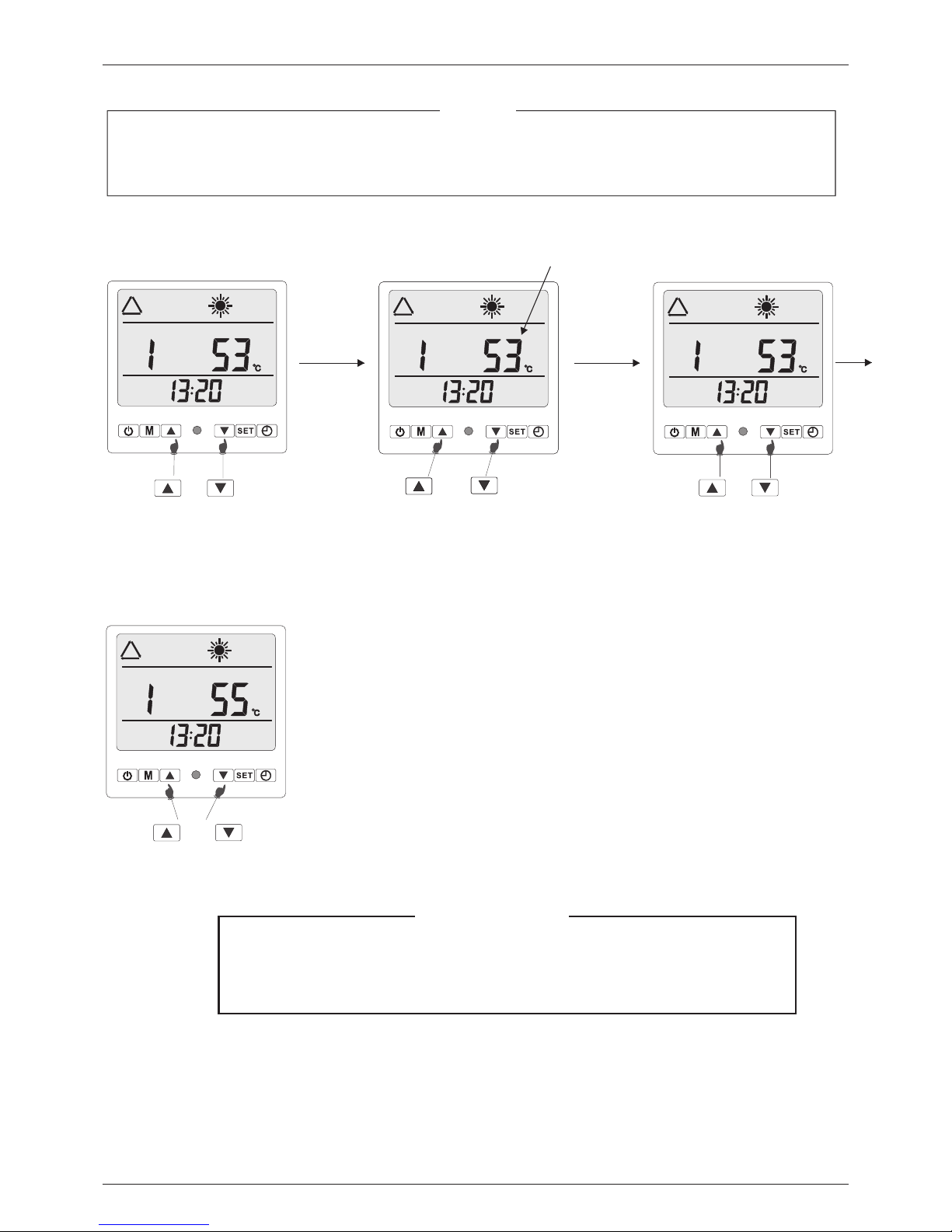
7.3 Water Temperature Setting
When the heat p ump is switched o n, just press or to check the pa rameter.
Initi al st ate
For exa mpl e
press or
“1" mea ns pa rameter of wat er ta nk temperatu re.
Hot Water S eri es
16
Press “ up” a nd “down” key fo r 3~5 s econds, “Bee ~~! !” sound is hear d and the keys are lock ( vice versa).
Page 19
3
1
Set the w ate r outlet tempe rat ure as follows :
Hot Water S eri es
17
Press and fo r 3~5 seconds
till “B ee~ ~!!” sound hea rd; a nd the
tempe rat ure value flas hes .
Press or to ad just
the wat er ou tlet tempera tur e.
Flashing
Press and fo r 3~5 seconds
to save the se tting.
Press or to ch eck the
param ete r, please choos e “1"
(0~11) for water tank t emp erature
setti ng (s ee “1" on the abov e
pictu re) .
NOTICE
Durin g par ameter setti ng, i f no operation f or mo re than 8 second s, th e interface of t he co ntroller pan el
will au tom atically bac k to th e main view.
Press ON/O FF key and Mode ke y wil l defrost forc edl y.
The wat er ou tlet tempera tur e of the domesti c hot w ater heat pump s is se t
with 55 ~60℃ b efore delive ry in f actory.
It is sugges ted to be 55℃ for exp and ing the workin g lif e of the compres sor
and who le sy stem.
IMPORTANT
Page 20

3
1
7.4 Clock Setting
Set the syst em time accord ing t o the local time a s fol lows:
Step 1
Step 2
Press to sta rt clock setting.
Press agai n to start
setti ng ho ur value. The h our
value f las hes.
Step 4
Flas hi ng
Step 5
Flas hi ng
Step 3
Flas hi ng
Flas hi ng
Step 6
Flas hi ng
Press or to ad just
the hou r val ue.
Press to sel ect minute and
the min ute v alue flashes .
Press or to ad just
the minute va lue.
Press to con firm the value
and ret urn t o main interfa ce.
Main In ter face
The cur ren t time is adjust ed fr om 13:20 to 15:3 0.
Hot Water S eri es
18
NOTICE
At the first t ime, the time shoul d be defined acc ord ing to local tim e zon e; otherwise , the accuracy of
“Timer on/Timer off” would be infl uen ced.
Page 21

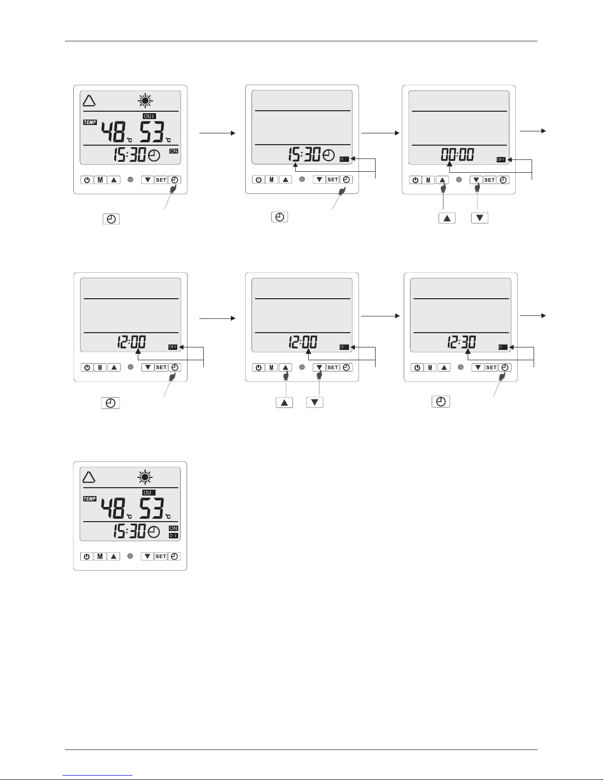
7.5 ON/OFF Timing Setting
With t his f uncti on, t he heat p ump c an turn o n or tu rn off auto mat icall y at th e set tim e.
When t he ti me poin t of “Timer o n” is arrive d, the heat pu mp starts; t hereafte r, the “ON /OF F” coul d be co ntrol led
auto mat icall y bas ed on the s ett ing tem per ature .
When the time po int o f “Timer off” is a rrive d, th e hea t pump is shut down; sub seq uentl y, the machin e cou ld no l onger be
cont rol led automati cally based on the setting temp erature; it will be restart ed u nti l th e ne xt t ime poi nt o f “Timer on” is
arri ved o r the key i s pre ssed.
Belo w exa mples s how h ow to set t he he at pump t o swi tch on at 9 :10 a nd swit ch off at 1 2:30.
Step 2
Flash
Flash ing
Flash ing
Step 3
Step 4
Flash ing
Step 5
Flash ing
Step 6
Step 1
Press to sta rt ON time
setting.
Press agai n to select hour
and the h our v alue flashes .
Press or to ad just
the hou r val ue.
Press or to ad just
the min ute v alue.
Press to con firm the value and
turn to n orm al display.
Press to sel ect minute and
the min ute v alue flashes .
pleas e tur n to
the nex t pag e
Hot Water S eri es
19
Totall y 1 ON/ OFF tim ers c an be set . And th ey can be a ppl ied to us e for e very da y or only one da y.
In timer se tting stat us, t he figure be low N O. repr ese nts the time r seq uence . If it s hows “--:- --“ o n botto m, it m eans
time r inv alid.
To cance l the t imer, pl eas e refer t o the i nstru cti on for ti mer s ettin g and set it to be “ ---:---“
NOTICE
Page 22
Step 8
Flash ing
Flash ing
Step 9
Flash ing
Step 10
Flash ing
Step 11
Flash ing
Step 12
Refer t o the p revious page o r bro ught forward ( b.f .)
Press to sel ect hour and
the hou r val ue flashes.
Press or to ad just
the hou r val ue.
Press to sel ect minute and
the min ute v alue flashes .
Press or to ad just
the min ute v alue.
Step 7
Press to sta rt OFF time
setting.
Main In ter face
Press to con firm the value
and tur n to ma in interface .
Hot Water S eri es
20
Page 23
Hot Water S eri es
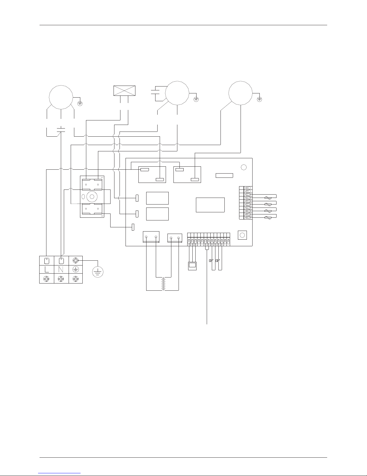
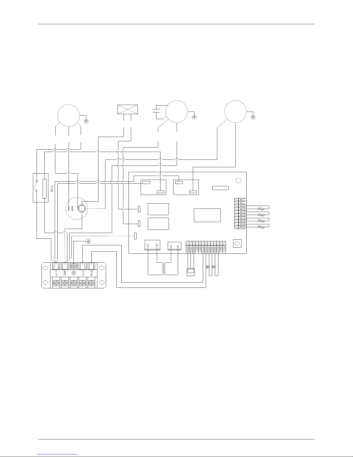
8. Circuit drawing
Model: YASBP-25HL
21
4
3
4
3
123
4
567 8
9
0
1
1
2
3
4
5
6
7
98
1
0
1
1
2
1
13
Compressor
4-Way Valve
BR
Fan
FAN
BL BL
OR
BK WH
REBLBK
CM
R
S
C
Pump
GND
T.S
A.S
C.S
GND
GND
GND
R.S
Tank Temp. Sensor
Ambient Temp. Sensor
Coil Temp. Sensor
Exhaust Air Temp. Sensor
MCU
AC - L
AC - N
CQC
250VAC
2.5mm *2
N
High Pressure Switch
Low Pressure Switch
LCD Controller
GND
GND
GND
GND
GND
GND
OB
H-P.S
L-P.S
F.S
NET
12V
OB
LP
HP
Flow Switch Must be Installed Here
220V/AC 12V/AC
Transformer
220V/1Ph/50Hz AC
PUMP
Page 24
Hot Water S eri es
Model: YASBP-38HL, YASBP-56HL, YASBP-90HL
22
4
3
4
3
CM FAN PUMP
4-Way Vale
Fan Pump
4-Way Vale
Tank Temp. Sensor
Ambient Temp. Sensor
Coil Temp. Sensor
Exhause Air Temp. Sensor
AC 220V/1Ph/50Hz Flow Switch
Transformer LCD Controller
220V/AC 12V/AC
AC - N
AC - L
MCU
BK
RE
BL
BL BL
OR
BK WH
BR
R C
S
COM
NO
COM
OCC
GND
HP
LP
High Pressure Switch
Low Pressure Switch
Page 25

Hot Water S eri es
9. Maintenance and Trouble Shooting
9.1 Maintenance
The heat pump wat er he ater is an advanced leakage from connec tor s.
Keep t he su rrounding of the heat pump dr y,
equipment wit h hig h automization. The
clean and venti lat ed. Regularly clean the
reliability a nd op eration life of the heat pump c an
evaporator to k eep h igh heat exchanging
be expectedly g urr anteed and even increased b y
efficiency.
regular inspe cti on and effective maintena nce.
Check the insid e pip e connectors and refriger ant
The external wa ter f ilter should be cleaned
service port is d irty with oil. Make sure there is no
regularly to en sur e the cleanness of the water in
refrigerant l eak age.
the system and av oid d amage caused by
blockage in the f ilt er.
Before stoppi ng th e heat pump for long time,
drain out all wat er in t he pipes, and shut off the
All protectiv e set tings in the unit have been set
power supply, and put it into a shield. Full
before ex-factory. Users must not adjust it when
inspection of t he sy stem is required before nex t
the heat pump uni t is in u se.
operation.
Regular inspe cti on is required for the power
Users should ca ll th e installer or the seller eve ry
source and the wi rin g connection of the electri c
time when there i s an er ror on the heat pump
system. Loose w iri ng connection and electri c
controller.
components sh oul d be repaired in time.
Clean the conde nse r with phosphoric acid of
The water suppl y sys tem, relief valve of the wate r
15% consisten ce un der temperature of 50C -60C.
tank, water lev el co ntrol device and air discha rge
Run the circula tio n pump for 3 hours, and then
device need to be c hec ked regularly in case of
flush with fres h wat er for 3 times. When installi ng
low circulati on wa ter volume caused by air
the pipes, add a 3 wa y val ve on the pipes and
entering the sy ste m, to ensure enough capacit y
closed on outle t of it , for cleaning use. Corrosi ve
and reliabili ty of t he heat pump.
washing liqui d is forbidden to clean the
Check the water p ump a nd the valves on the
condenser.
pipes if they wor k wel l, and make sure there is no
23
Page 26

9.2 Parameter Checking.
Hot Water S eri es
24
Digit Meaning Range Default
Adjust(yes/no)
0
Tank set temperature hysteresis
0-30℃ 5℃
yes
1
Water tank temperature setting
8-55℃ 55℃
yes
2
Defros t Cycle
30-90Min 40Min
yes
3
The time point to enter defrosting in
heating
0-30℃ -5℃
yes
4
Exit defros t temperature
2-30℃ 15℃
yes
5
Exit condition of defrost time
1-12Min 8Min
yes
6
Water tank temperature setting
range (55/65)
0-1 0
yes
7
Res erved
yes
8
Com pensation(yes /no)
0-1 1
yes
9
Cyclic heating(yes/no)
0-1 1
no
A
Heater / pump selection
0-1 1
yes
B
Target superheat / 10
-F--F 0
no
C
Start tem perature
10-55 47
no
D
Exhaust temperature
-9--99℃
ajdus ted by technicians
E
Pipe temperature
-9--99℃
ajdus ted by technicians
F
Res erved
-9--99℃
ajdus ted by technicians
10
Ambient temperature
-9--99℃
ajdus ted by technicians
11
The actual num ber of steps / 10
0-40
no
Running time
0-9999h
ajdus ted by technicians
Protection / Failure Remote Controller
Water tank temp. sensor fault F0
Coil temp.sensor fault F1
Flow switch malfunction F2
Ambient temperature sensor fault F3
Protection of the exhaust temperature is too high F4
High voltage protection of the system F5
System voltage protection F6
Exhaust temperature sensor fault F7
The second time freezing protection in winter F8
Wired remote communication failure F9
Defrost Defrost display
9.3 Error Code.
Page 27

Hot Water S eri es
9.4 Trouble Shooting
Users should contact with the professional maintenance staff when there is a
problem with the heat pump. Maintenance stuff may need to refer to the following
table for troubleshooting.
Malfunction Possible Problems Disposing Methods
Heat pump unit is
out of operation.
1. Power source fault.
2. Loose connection of
power wire.
3. Power fuse burnt out.
4. Low water level switch is
not on.
1. Cut off the power source
and check.
2. check the power wire
connection.
3. Check the fuse.
4. Supply water until the
water level switch is on.
Water pump is
running but no
water circulation or
much noise made by
water pump
1. Few water in the system.
2. Air exists in the water
system.
3. Some valves are not
opened.
4. The water filters is
blocked up.
1. Fill water into the water
supply system.
2. Discharge air from the
water system.
3. Open all the valves in the
system.
4. Clean the water filter.
Low heating
capacity.
1. Lack of refrigerant.
2. Bad water system heat
preservation.
3. Low evaporator heat
transferring.
4. Low water flow volume.
1. leakage hunting and fix it,
discharge all the refrigerant
and inject the right amount.
2. improve the heat
preservation.
3. Wash the evaporator.
4. Clean the water filter.
Heavy frosting, low
heating capacity.
1. The evaporator is too
dirty.
2. Defrost sensor fault.
3. The 4 way valve can not
change direction.
4. Over long defrosting
duration.
1. Wash the evaporator.
2. Change a new defrost
sensor.
3. Check the solenoid if it is
energized.
4. Change the temperature
for entering defrost and the
duration.
High noise of
compressor.
1. Liquid refrigerant into
the compressor.
2. Interior component of
the compressor is faulty.
1. Check if the thermostatic
expansion valve is faulty.
2. Change the compressor.
25
 Loading...