

Page 1
HOT WATER
ECO-SOLUTION
Page 2

Page 3
Page 4
Page 5

Water O ut let
Water I nl et
Power C ab le Hole
Controller Ca bl e Hole
750
935
Length (mm)
264
282
Wide (mm)
405
650
A (mm)
493
545
Height (mm)
FFD-3.8
FFD-5.4
Model
4. 2 Dimension
3
L
H
W
A
High Pressure G au ge
274
330
B (mm)
B
1002 302
650620
FFD-7.6
330
1002 302
650620
FFD-9.3
330
Fire Fly Domesti c Hot Water Air to Wate r Heat Pump
Page 6

Page 7

Page 8

Page 9

Page 10

Page 11

4.5 Components
Compressor
The depe ndable high efficiency
compre ssor, with op timized R410A
system , can achieve high wa ter
temper ature up to 60 degree s Celsius;
while en sures long life of the compressor.
4-Way Valve
The reliable 4 way valve ca n
avoid gas mixing, and ens ure
stable defrosting.
Condenser
The Tube-in-shell h eat exchanger as
condenser, with big ger heat
exchanging area and hig her
efficiency.
Evaporator
The hydrophilic fin-t ube heat
exchanger has big heat ex changing
area and rational fin dis tance, thus
significantly impro ves heating and
defrosting efficien cy.
ABS Plastic Fan
The exterior motor fan, w ith multiple fa n
blades, is strictly bal anced. The mult iple
fan blades run slower, and make sure
high air volume, thus lar gely brings dow n
the noise.
Photos Features/AdvantagesComponents
9
Circulation Pump
Fa mous brand w ater circu lation
pu mp, e.g. WIL O.
Re frigeran t
R4 10A gas, env ironment -friendl y
an d of high perf ormance.
Fire Fly Domesti c Hot Water Air to Wate r Heat Pump
LC D Controll er
In telligen t controll er with LCD
re adout and au tomatica l defrosting;
4- timer func tion avail able;
12 m eter contr oller wire .
Page 12

Page 13
5.2 Water System Installation
5.2.1 Water Tank Installation
5.2.2 Water Piping Installation
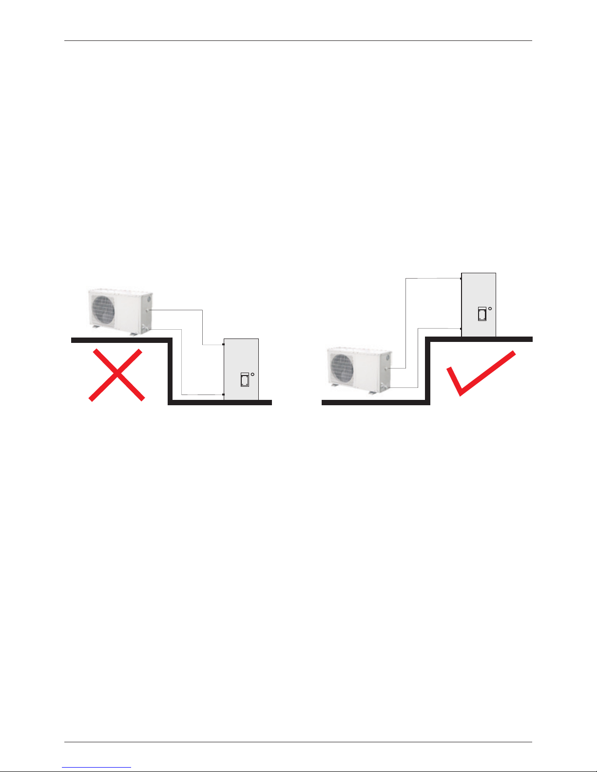
1. The water tank should be p ut in a place where suggested to install th e heat pump, the wa ter
ambient temperature i s more higher. tank and the circulatio n pump at the same le vel.
Besides, the height dif ference betwe en the heat
2. It can be installed eith er outdoors or on t he
pump and the water tank sho uld be no more than
roof-top (some elements suc h as the size of
2 meters, when water tank p osition is high er than
water tank and the bearin g capability of t he
that of the heat pump.
building should be cons idered). Inst allation on
roof-top should be based on sup port such as 4. Do not install the water t ank in a pollutiv e or
crossbeam or pillar. corrosive area.
3.The water tank should n ot be installed l ower
than the foundation of th e heat pump; It is
1. Drainpipe and overfl ow pipe should be carried out for the water s upply valve and t he
installed near the gutt er or the sinkhol e for stop valve of the system (a ccording to loc al
draining water more eff iciently. Discharg e valve ambient temperature ) for avoiding ic ing of the
is necessary on the drain pipe. water supply pipe and the v alves.
2. Service valve needs to b e installed bef ore the 6. Keep the water pipes straigh t and the pipelin e
magnet-valves on the syst em pipeline for f urther allocation reasonab le; Reduce pipe t urnings as
inspection. many as possible to reduc e water resista nce.
3. The pressure of the wate r outlet should b e 7.Prevent the pipelin e and the connect ors from
between 0.3MPa a nd 0.6MPa. water leakage.
4.It is recommended to us e metal pipelin e such 8 .The water pres sure bearing ca pability of each
as stainless steel pipe s, internal-p lastic pipes, part of the piping system s hould be tested a fter
internal stainless st eel pipes or copp er pipes the instal lation is finis hed; Drainage s hould be
etc; Telesco pic issue of the pi peline betwee n done to create a clean int erior system.
heat pump unit and water ta nk should be
9. Measures of heat prese rvation for the h ot
considered if plastic p ipeline such as P PR pipe
water pipeline need to be c onducted afte r
and AB S pipe etc. is us ed.
assuring no water leaka ge.
5. In winter, heat pres ervation may ne ed to be
11
Water
Tank
Water
Tank
Fire Fly Domesti c Hot Water Air to Wate r Heat Pump
Page 14

Installation Scheme:
Shut Off Valve
Solenoid Valve
Check Valve
Electric Heater
Water Pump
Y-Shape Filter
12
Flow Switch
Heat Pump
Controller
Heat Pump
Dinning Hall
Filter
Filter
Flow Switch
(can omit)
Guest Room
Sauna Room
Drainage
Water Tank
Check Valve
Water tank
temp. sensor
5.3 Power Source Installation
Recommended wire spec ification
2
3x1.5mm
Po wer Cable
LC D controll er
Se nsorMo del Wa ter Pump
FF D-3.8
FF D-5.4
FF D-7.6
2
3x1.5mm
2
3x2.5mm
2
3x0.75mm
2
3x0.75mm
2
3x0.75mm
2
3x0.35mm
2
3x0.35mm
2
3x0.35mm
2
2x0.35mm
2
2x0.35mm
2
2x0.35mm
NOTE : the above specification is the low est one we recomm end. Please choose bigger wires if additional
power is required under i nstallation .
FF D-9.3
2
3x2.5mm
2
3x0.75mm
2
3x0.35mm
2
2x0.35mm
Fire Fly Domesti c Hot Water Air to Wate r Heat Pump
Page 15

M
SET
M
SET
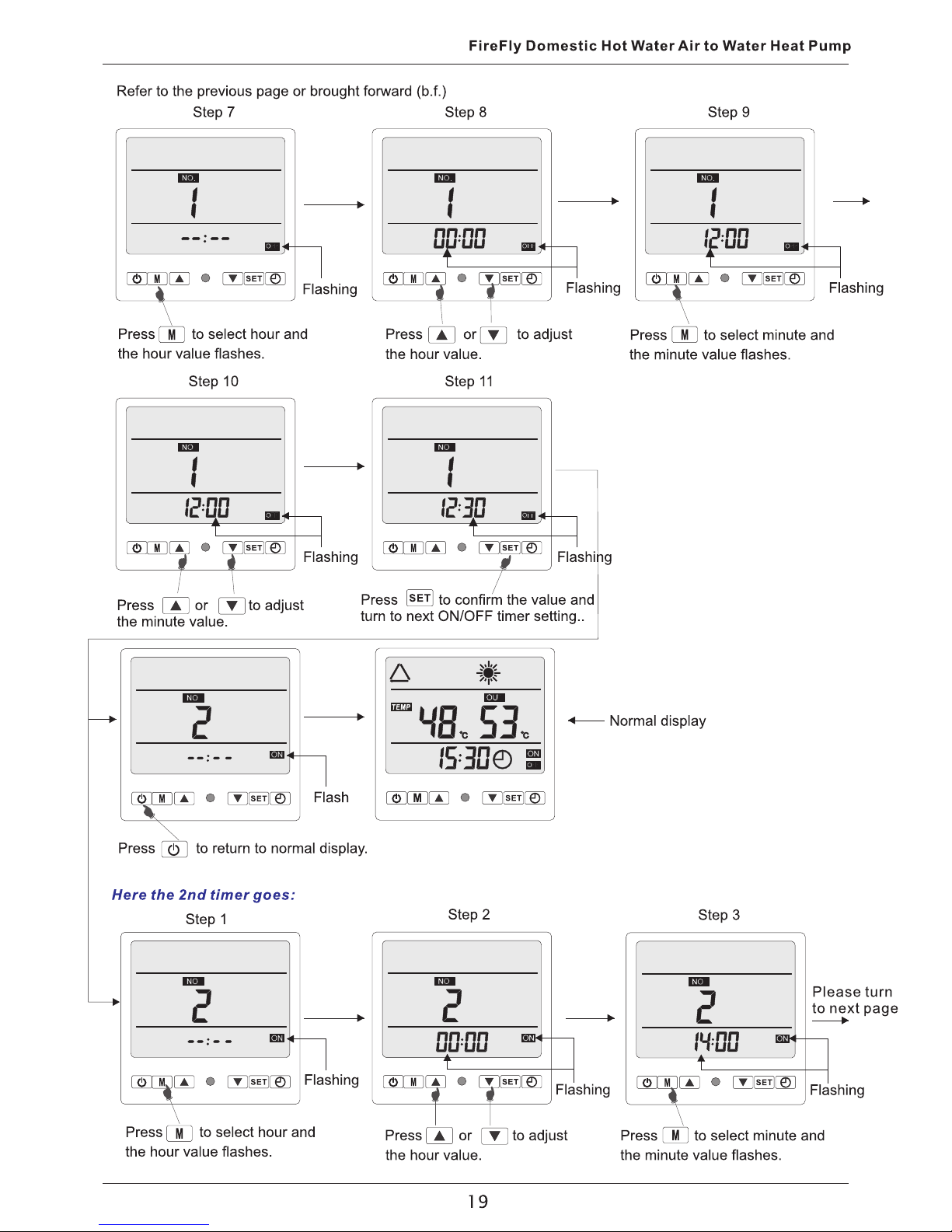
5.4. Wire Controller Installation
The wire d co ntroller is ori ginally fixed on th e ma intenance door of t he machi ne; please refe r to below
step s if you want to in stall it on the wal l:
?1.Take down the contr oller from the ma chine. The com munication wire is connect ed with the circuit
boar d, separate t hem from where th ey match.
?2.Us e a screwdriv er to open the clip a s picture 1, se parate the controller as 2 par ts, as pictur e 2.
?3.On the wall that you a re go ing to insta ll th e contr oller, drill 2 hol es at a level parallel to the sight l ine a s
pict ure 3. The hole dista nce is 60mm, diameter is 8mm.
?4.Pl ace the pla stic screws of the enclo sure into the hole, and use the tapping screw (ST4* 16 D-1)
encl osed to fix the b ack cover of cont roller on the w all, as picture 4.
?5.Ma tch the front and back covers pe rfectly, as pictur e 5, make sure that it is fixed firm ly on the wall.
?6.Co nnect the com munication wi re well.
1 2
5
6
The fr ont cover
60mm
Φ8
3 4
Outl et of the commu nication wire
ATTENTION :
Plea se don't use ke en-edged thin gs to hit the con troller fac e and keys, or it may c ause damage .
When t he controll er is fixed on the wa ll, don't pul l the communi cation wire, or i t may cause poo r contact.
The ba ck cover
13
Fire Fly Domesti c Hot Water Air to Wate r Heat Pump
Page 16
14
Page 17

Page 18

Page 19

17
Page 20

Page 21
Page 22

Page 23

Page 24

Page 25

Page 26

Page 27

Page 28
Page 29

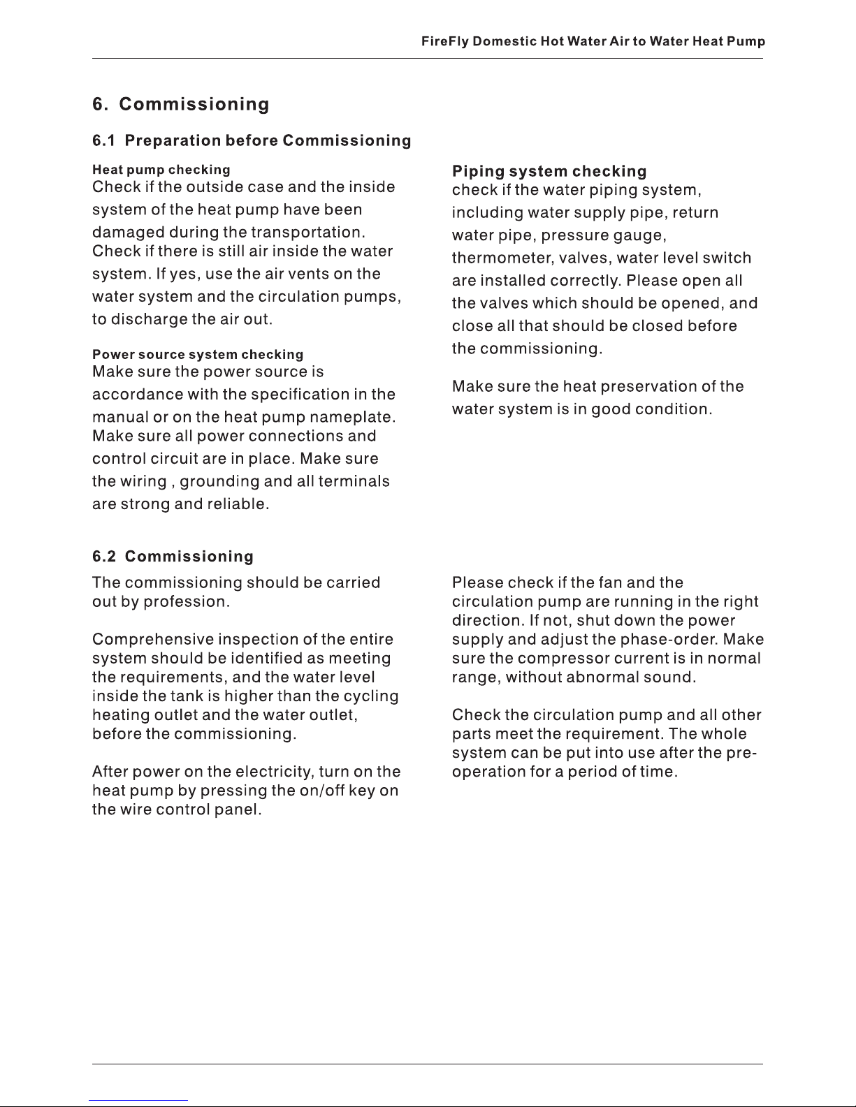
9. Maintenance and Trouble Shooting
9.1 Maintenance
The heat pump water heate r is an advanced clean and ventilated. R egularly clea n the
equipment with high aut omization. Th e evaporator to keep high h eat exchangin g
reliability and opera tion life of the he at pump can efficiency.
be expectedly gurrant eed and even incr eased by
Check the inside pipe con nectors and ref rigerant
regular inspection an d effective mai ntenance.
service port is dirty wit h oil. Make sure th ere is no
The external water filt er should be clea ned refrigerant leakage.
regularly to ensure the c leanness of the w ater in
Before stopping the hea t pump for long tim e,
the system and avoid dama ge caused by
drain out all water in the pi pes, and shut off t he
blockage in the filter.
power supply, and put it into a shie ld. Fu ll
All protective settin gs in the unit have b een set inspection of the syste m is required bef ore next
before ex-factory. User s must not adjust i t when operati on.
the heat pump unit is in use.
Users should call the ins taller or the sel ler every
Regular inspection is r equired for the p ower time when there is an error o n the heat pump
source and the wiring con nection of the el ectric con troller.
system. Loose wiring co nnection and el ectric
Clean the condenser wit h phosphoric ac id of
components should be re paired in time.
15% consistence under t emperature of 5 0C-60C.
The water supply system , relief valve of t he water Run the circulation pum p for 3 hours, and th en
tank, water level contr ol device and air d ischarge flush with fresh water for 3 times. When inst alling
device need to be checked r egularly in cas e of the pipe s, add a 3 way valve on the pipes and
low circulation water v olume caused by a ir closed on outlet of it, for c leaning use. Co rrosive
entering the system, to e nsure enough ca pacity washing liquid is forbidden to clean the
and reliability of the he at pump. condenser.
Check the water pump and th e valves on the Cl ean the inside of the w ater tank after b eing
pipes if they work well, an d make sure there i s no used for a period(usuall y two months, and
leakage from connecto rs. according to local wate r quality.)
Keep the surrounding of the hea t pump dry,
27
Fire Fly Domesti c Hot Water Air to Wate r Heat Pump
Page 30

Page 31

Page 32
0
5
10
15
20
25
30
35
40
45
50
0
5
10
15
20
25
30
35
40
45
50
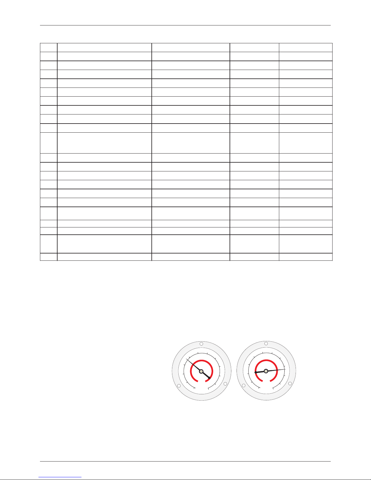
9.5 Parameter Number and Description Table.
The ma nometer is a ki nd of high pressu re equipmen t, when the hea t pump is on, the man ometer poin ter
2
woul d point to the pr essure value of r efrigeran t, the max. value of protectio n is 42kg/Cm . When t he heat
°
pump i s off, t he pointer wo uld point to the same value as act ual ambient t emperature (e .g. 28 C) and r elated
2
air pr essure (e.g .18kg/ Cm ).
Plea se check the ma nometer when yo u restart the h eat pump after not using for a lon g time, if it sho ws
° °
ambi ent tempera ture valve is sma ller than 2 C (Wh en the ambien t temp. is high er than 2 C), it me ans that
refr igerant has l eaked a lot, and yo u need to confi rm with professional engin eer as soon as po ssible.
NOTE : the machine o ff cod e (The No. 13, para meter in the pr evious table) :
2: Water tank temp . sensor brea kdown
3: Eva porator coi l temp. sensor br eakdown
4: Dis charge temp . sensor breakd own
5: Dis charge temp . is too high, swit ch off the unit
11: Anti-fro zen finishe d, switch off the uni t
12: Hi gh-pressu re switch cutti ng
13: Me et set temp
14: Co ntroller po wer off
No. 32
19: Water flow swi tch breakdo wn
No. Content Scope Default Memorized station
0 The incoming electric memorized sign 0-no effective 1-effective 1 The main board
1 Daily circulation sign 0-no effective 1-effective 1 the wire control panel
2 the setting area X 2℃~10℃,Unit:℃ 3 The main board
3 the setting area Y 0℃~3℃,Unit:℃ 0 The main board
4 The interval for defrosting 15~99,Unit:minute 45 The main board
5 Defrosting-on temperature -9~5℃, Unit:℃ -3 The main board
6 Defrosting-off temperature 5~20℃,Unit:℃ 10 The main board
7
Compressor’s exhaust air protection 90~120℃,Unit:℃ b8: means 118℃ The main board
8 Evaporator coil temperature 1 Unit:℃ Scope:-9℃-80℃ No Setting
9
Discharge gas temperature 1 Unit:℃
98: means 98℃
A8: means 108℃
b8: means 118℃
No Setting
10 ambient temperature Unit:℃ Scope:-9℃-80℃ No Setting
11 Compressor continuous running time Unit:minute Scope:0-99 No Setting
12 Fan continuous running time 1/4 Unit:Second No Setting
13 Compressor auto-off code 1 No Setting
14 On-off imported state Especial:sixteen No Setting
24 Auxiliary heat source 0-no effective 1-effective 0 The main board
25
Water tank temp./water outlet temp.
compensation
-5~5℃, Unit:℃
1
The main board
29 Evaporator coil t emperature 2 Unit:℃ Scope:-9℃-80℃ No Setting
32 Compressor auto-off code 2 No Setting
37
Discharge gas temperature 2 Unit:℃
98: means 98℃
A8: means 108℃
b8: means 118℃
No Setting
48 Start ambient temp.(auxiliary heat source) 2~15℃, Unit:℃
7
The main board
20: De frosting pr eparation
21: De frosting fi nish
22: Er ror phase or la ck of phase with po wer supply,
then s witch off the machi ne
27: Lo w-pressur e switch cuttin g
22: Hi gh-pressu re switch cutti ng during wat er tank
temp . is high
32: Hi gh-pressu re switch cutti ng during def rosting
30
9.6 Manometer Instruction
Fire Fly Domesti c Hot Water Air to Wate r Heat Pump
0
Page 33

Page 34

Page 35

Note:
Spec ification s in this user manu al are subjec t to change wit hout prior noti ce that FireF ly may bring the
late st innovati ons to their cust omers.
Whil st every effort is ma de to ensure that a ll specific ations are co rrect, printi ng errors are b eyond
Fire Fly’s control; Fi reFly can not be he ld responsi ble for these e rrors.
Energy Efficient Homes and Businesses (Pty) Ltd
Cell: 083 530 0930 (Derek de Brés)
Office: 0861 347 336
0861 EGREEN
Fax: 086 578 1737
Derek@energysefficienthomes.co.za
www.energyefficienthomes.co.za
www.energyefficientbusinesses.co.za
 Loading...