

Page 1

HOT WATER
ECO-SOLUTION
Air Source Heat Pump
Applicable Models: FFC-10
FFC-20
FFC-30
FFC-38
FFC-45
FFC-55
FFC-63
Page 2

Hot Water Seri es
CONTENTS
9. Maintenance and Trouble Shooting
9.1 Maintenance
9.2 Failure code checking
9.3 Common failures code
9.4 Parameter checking and adjustment
9.5 Parameter number and description table
9.6 The manometer instruction
7. Controller Operation
7.1 Illustration for the keys
7.2 Illustration for LCD display
7.3 Water temperature setting
7.4 Clock setting
7.5 ON/OFF time setting
7.6 Timer mode setting
6. Commissioning
6.1 Preparation Before Commissioning
6.2 Commissioning
5. Installation
5.1 Heat Pump unit Installation
5.2 Water System Installation
5.2.1 Water Tank Installation
5.2.2 Water Piping Installation
5.3 Power Source Installation
4. Technical data
4. 1 Parameter table
4. 2 Dimension
4.3 Performance Curves
4.4 System Diagram
4.5 Components
1. Features/Benefits
2. Notes/Precautions
3. Model Number Nomenclature
8. Circuit drawing
1
1
2
2
2
4
6
13
14
15
15
17
17
17
19
21
21
21
22
22
23
23
27
24
25
29
33
33
34
34
35
36
36
5.4 Wire controller installation
20
9.7 Trouble Shooting
37
7.7 Timer cancelling
28
Page 3

1 Features/Benefits
Wi de Applicatio n Ranges designed to minimize in stallation sp ace.
The Thermal Master Seri es is designed fo r Full Conside ration for Nois e Control
Compressor rubber fee t are specially s elected for
offering central hot wa ter for bigger ho uses, as
reducing vibration. S pecially, compress or sound
well as commercial buil dings such as hot els,
jacket is available for e very unit. Well-balanced
offices, schools, hos pitals, apart ments etc. The
fans and fan motors, with t he optimized fa n
hot water outlet range is w ide from 20DegC t o
holder, contribut es to the low noise o peration. The
60DegC, meeting deman ds for most hot wat er
cabinet inside is insul ated to reduce no ise
project. The performa nce is at wide ambi ent
transmission.
temperature range fro m -10~45DegC. M odular
control system is avail able to meet the de mand of
Reliable Design and Str ict Quality Con trol
huge hot water projects .
Standard safety featu res for the refri gerant circuit
include high-pressu re switch and low -pressure
Assuring You Get Gran ts from Your Go vernment
switch to detect loss of re frigerant, as w ell as
Designed for high effic iency perform ance over a
deficient water flow. E quipment safe ty features
lifetime of operation . The annual aver age COP is
include water loop temp erature monit oring,
up to 5.0. Efficiencies s tated are in acco rdance
voltage protection, w ater coil freez e protection.
with EN14511. The water p ipes and refrig erant
All safety features are t ested and run at th e factory
pipes are well insulate d to minimize the h eat loss.
to assure proper operat ion of all compon ents and
Durable and Long Life
safety switches.
High efficiency compr essor for all uni ts, with
All components are care fully designe d and
durable features agai nst high temper ature and
selected for enduranc e, durability, and car efree
high pressure for long li fe. The coaxial c oil heat
day-to-d ay operation. E ach unit is fully tested in
exchangers are durabl e for anti-corr sion, hard
performance and safet y before exit fac tory.
water, high pressur e and unexpecte d freeze
Simple Maintenance an d Serviceabil ity
caused by power cut-off.
Full access fo r maintenance or service is provided
Strong Cabinet from the maintenance pa nel, for better f lexibility in
Standard unit fabrica tion consists o f heavy gage
confined space. Easy re moval of the cont rol box
galvanized sheet meta l cabinet const ruction that
from the unit provides ac cess to all refri gerant
provides maximum stre ngth. All inter ior sheet
components. The refri gerant circui t is easily
metal surfaces are powd er-paint ed for maximum
tested and serviced tho ugh the use of high a nd
corrosion protectio n to ensure resil ience for long
low pressure ports inte gral to the refri gerant
term vitality. Compact, stac kable cabinet s are
circuit.
Hot Water Seri es
1
2 Notes/Precautions
The installation, com missioning an d wires are apart from hot or m oving parts [eg :
maintenance of the syst em should only be d one compressor, fan] of the s ystem to avoid
by qualified personne l with adequate k nowledge damage to the wires.
Anti-freezing measu res must be well do ne to
of the relevant standar ds and local regu lations
avoid damage to the water s ystem and the hea t
as well as experience wit h similar syste ms.
pump water heat exchang er.
Please make sure the wate r flow is suffici ent
Please make sure the lift ing and
all the time.
transportation are sa fely done accor ding to
All ground line connect ions must be prep ared
the heat pump size and weig ht.
in accordance with rele vant local regu lations.
It is very dangerous work d one at the facili ty
To reduce the ri sk of electrica l insulation
without previously cu tting off the ele ctricity from
faults, you first make th e connection of t he
the main power source.
protective conducto r of the heat pump sa fe
When installing the sys tem, please ens ure
according to local regu lations.
that no contaminants en ter the water cycle.
When installation,ma ke sure that the inside
■
■
■
■
■
■
■
■
■
Page 4

Hot Water Seri es
3 Model Number Nomenclature
FFC-20
10 -3 HP 2
55 -1 5HP 63-18HP
0- 5HP 30 -8HP 38 -10HP 45 -1 2HP
Heat ing Capacit y
He at Pump Type
Input Power
Running Current
Max. Input Power
Max. Running Current
Refrigerant
Compressor
Compressor Type
Compressor Quantity
Outlet Water Temp
Max. Outlet Water Temp
Hot Water Yield
Water Flow
Condenser
Water Pressure Drop
Water Connection Tube
Noise
Electric Protection
Mechanical Protection
Power Supply
Heating Capacity
Net/Gross Weight
Dimension
Packing Dimension
10.5
2.55
12.46
3.57
17.45
R410a
Toshiba
Rotary
1
55
60
226
2.3
Tube in shell
40
DN25
<55
I
IPX4
220/1/50
FF C- 10
87/103
752x690x765
840x750x900
kW
kW
A
kW
A
ºC
ºC
L/h
3
m /h
Kpa
mm
dB(A)
V/Ph/Hz
kg
mm
mm
19
4.55
7.83
6.37
10.97
R410a
Sanyo
Scroll
1
55
60
408
4.1
Tube in shell
50
<57
I
IPX4
380/3/50
FFC-20
119/137
752x690x965
840x750x1100
DN25
30
7.2
12
10.08
18.36
645
6.4
55
<58
380/3/50
FF C- 30
236/279
1450x702x950
1525x805x1110
R410a
Scroll
2
55
60
Sanyo
Tube in shell
Dn40
I
IPX4
Measuring condition : Dry/wet bulb te mp 20ºC/15ºC; Wa te r in le t/ ou tlet temp 15ºC/55ºC.
4. Technical data
4. 1 Parameter table
2
Page 5

Hot Water Seri es
Input Power
Running Current
Max. Input Power
Max. Running Current
Refrigerant
Compressor
Compressor Type
Compressor Quantity
Outlet Water Temp
Max. Outlet Water Temp
Hot Water Yield
Water Flow
Condenser
Water Pressure Drop
Water Connection Tube
Noise
Electric Protection
Mechanical Protection
Power Supply
Heating Capacity
Net/Gross Weight
Dimension
Packing Dimension
kW
kW
A
kW
A
ºC
ºC
L/h
3
m /h
Kpa
mm
dB(A)
V/Ph/Hz
kg
mm
mm
38
9.2
15.84
12.88
22.18
817
8.2
55
<60
FF C- 38
249/294
1450x702x1060
1525x805x1220
380/3/50
R410a
Sanyo
Scroll
2
55
60
Tube in shell
Dn40
I
IPX4
45
10.8
18.6
16.2
27.89
967
9.7
55
<61
FF C- 45
268/316
1450x702x1260
1525x805x1420
380/3/50
R410a
Scroll
2
55
60
Sanyo
Tube in shell
Dn40
I
IPX4
Measuring condition : Dry/wet bulb te mp 20ºC/15ºC; Wa te r in le t/ ou tlet temp 15ºC/55ºC.
3
55
13.5
23.4
20.25
33.00
1182
11.8
55
<63
FF C- 55
398/460
2150x765x1290
2250x865x1450
380/3/50
R410a
Sanyo
Scroll
3
55
60
Tube in shell
Dn50
I
IPX4
63
16.0
27.5
24.0
42.00
1354
13.5
55
<63
FF C- 63
428/490
380/3/50
R410a
Scroll
3
55
60
Sanyo
Tube in shell
Dn50
I
IPX4
2150x765x1290
2250x865x1450
Page 6

L
H
W
A
High Pr ess ure Gau ge
High Pr ess ure Gau ge (s ys tem 2)
Low Pre ssu re Gaug e (sy st em 2)
Low Pre ssu re Gaug e
Wat er Outl et
Wat er Outl et
Wat er Inle t
Wat er Inle t
Pow er Cabl e Hol e
Pow er Cabl e Hol e
Wi re Co ntrol ler Cable H ole
Wi re Co ntrol ler C able Ho le
Hot Water Seri es
752
1450
752
Length(mm)
690
702
690
Wide(mm)
470
755
470
A(mm)
765
950
Height(mm)
965
FFC-10
FFC-20
FFC-30
Model
4. 2 Dimension
4
L
H
W
A
High Pr ess ure Gau ge (s ys tem 1)
Low Pre ssu re Gaug e (sy st em 1)
785
708
785
B(mm)
B
B
3010,20
Page 7

Hot Water Seri es
2150
1450
1450
2150
Length(mm)
765
702
702
765
Wide(mm)
757.5
755
755
757.5
A(mm)
1290
1060
1260
Height(mm)
1290
FFC-55
FFC-63
FFC-38
FFC-45
Model
5
L
H
W
A
680
708
708
680
B(mm)
B
L
H
W
A
B
Wat er O utlet
Wat er I nlet
Pow er C able Hole
Wi re Contro ller Cabl e Hole
High Pres sure Gaug e
(system 1/syste m2 /syst em 3)
Low Press ure Gauge
(system 1 /system 2/ syste m3 )
High Pres sure Gaug e (s ystem 2)
Low Press ure Gauge ( sy stem 2)
Wat er O utlet
Wat er I nlet
Pow er C able Hole
Wi re Contro ller Cabl e Hole
High Pres sure Gaug e (s ystem 1)
Low Press ure Gauge ( sy stem 1)
A
55,6338,45
Page 8

Hot Water Seri es
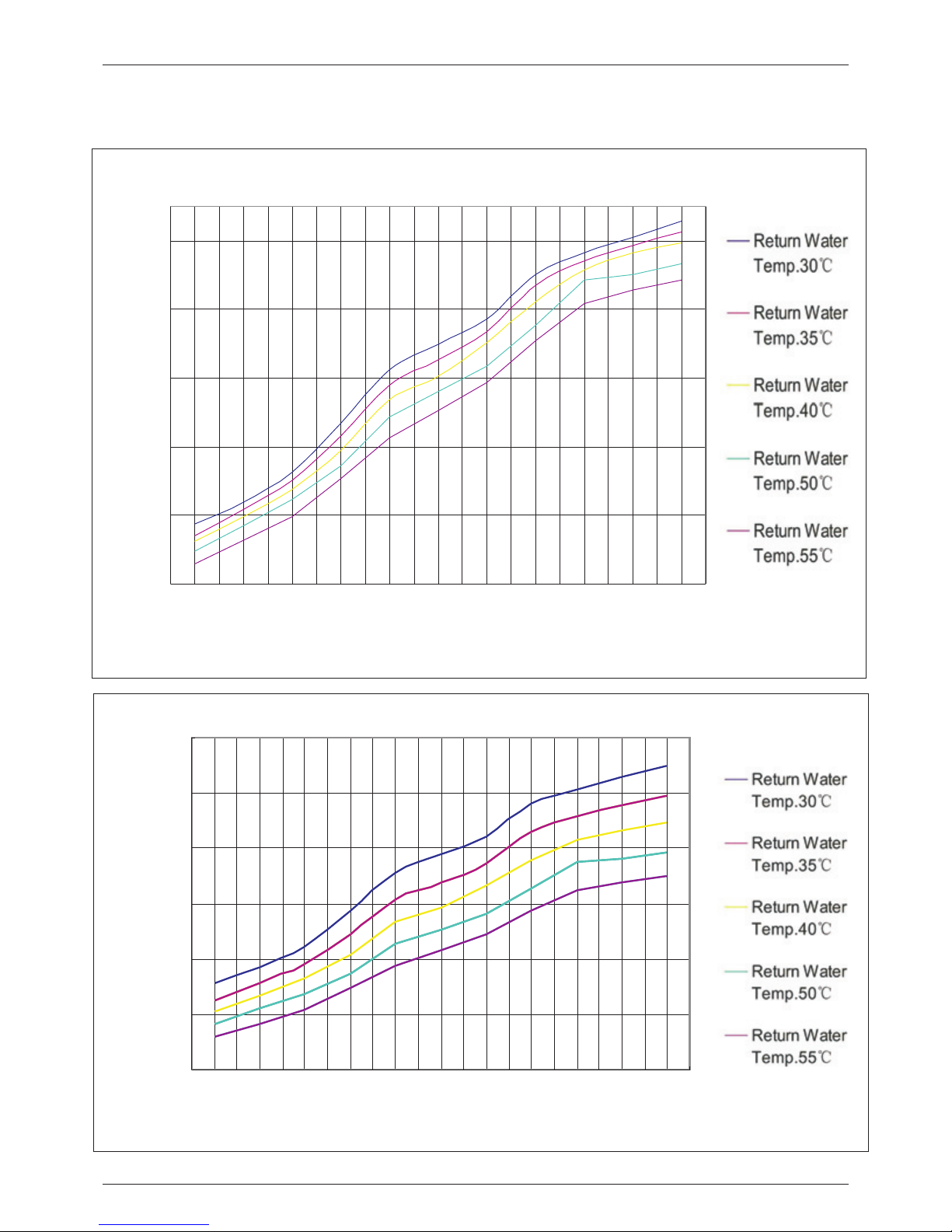
4.3 Performance Curves
Model: FF-10
6
Heating Capacity Curves
2000
4000
6000
8000
10000
12000
14000
-10 -5 0 5 10 15 20 25 30 35 40
Ambient Temp. (℃)
H e a ting C a p aci ty (W)
30
35
40
50
55
C O P Curves
1.00
2.00
3.00
4.00
5.00
6.00
7.00
-10 - 5 0 5 10 15 20 25 30 35 40
A m bie n t T emp. (℃ )
C O P
Page 9

Hot Water Seri es
Model: FFC-20
7
Heating Capacity Curves
5000
8000
11000
14000
17000
20000
23000
26000
-10 -5 0 5 10 15 20 25 30 35 40
Ambient Temp. (℃)
H e a ti n g C a p a c ity (W)
30
35
40
50
55
C O P Curves
1.00
2.00
3.00
4.00
5.00
6.00
7.00
-10 - 5 0 5 10 15 20 25 30 35 40
A m bie n t T emp. (℃ )
C O P
Page 10

Hot Water Seri es
Model: FFC-30
8
Heating Capacity Curves
10000
15000
20000
25000
30000
35000
40000
45000
-10 -5 0 5 10 15 20 25 30 35 40
Ambient Temp. (℃)
H e atin g C apa c ity (W)
30
35
40
50
55
C O P Curves
1.00
2.00
3.00
4.00
5.00
6.00
7.00
-10 - 5 0 5 10 15 20 25 30 35 40
A m bie n t T emp. (℃ )
C O P
Page 11

Hot Water Seri es
9
Model: FFC-38
Heating Capacity Curves
15000
20000
25000
30000
35000
40000
45000
50000
55000
-10 -5 0 5 10 15 20 25 30 35 40
Ambient Temp. (℃)
H e ati n g C a p a city (W)
30
35
40
50
55
C O P Curves
1.00
2.00
3.00
4.00
5.00
6.00
7.00
-10 - 5 0 5 10 15 20 25 30 35 40
A m bie n t T emp. (℃ )
C O P
Page 12

Hot Water Seri es
10
Model: FFC-45
Heating Capacity Curves
15000
20000
25000
30000
35000
40000
45000
50000
55000
60000
-10 -5 0 5 10 15 20 25 30 35 40
Ambient Temp. (℃)
H eating C ap a c ity (W )
30
35
40
50
55
C O P Curves
1.00
2.00
3.00
4.00
5.00
6.00
7.00
-10 - 5 0 5 10 15 20 25 30 35 40
A m bie n t T emp. (℃ )
C O P
Page 13
Hot Water Seri es
11
Model: FFC-55
Heating Capacity Curves
20000
30000
40000
50000
60000
70000
-10 -5 0 5 10 15 20 25 30 35 40
Ambient Temp. (℃)
H e at ing C a pa c ity ( W)
30
35
40
50
55
C O P Curves
1.00
2.00
3.00
4.00
5.00
6.00
7.00
-10 - 5 0 5 10 15 20 25 30 35 40
A m bie n t T emp. (℃ )
C O P
Page 14

Hot Water Seri es
12
Model: FFC-63
Heating Capacity Curves
20000
30000
40000
50000
60000
70000
80000
90000
-10 -5 0 5 10 15 20 25 30 35 40
Ambient Temp. (℃)
H eating C ap ac ity ( W)
30
35
40
50
55
C O P Curves
1.00
2.00
3.00
4.00
5.00
6.00
7.00
-10 - 5 0 5 10 15 20 25 30 35 40
A m bie n t T emp. (℃ )
C O P
Page 15

Hot Water Seri es
4.4 System Diagram
Heating Mode
Water inlet
Water inlet
Water outlet
Water outlet
Defrosting Mode
High pressure switch
High pressure switch
Low pressure switch
Low pressure switch
4 way valve
4 way valve
Suction accumulator
Suction accumulator
Compressor
Compressor
Condenser
(fin-tube)
(fin-tube)
Evaporator
2 way
thermal
expansion
valve
2 way
thermal
expansion
valve
Evaporator
(Tub e in shell)
Condenser
(Tub e in shell)
13
Page 16

Hot Water Seri es
4.5 Components
Compressor
The dependable flexib le
compressor, with op timized
R410a system, can achie ve high
water temperature up to 6 0DegC,
while ensures long life o f the
compressor.
4-Way valve
The reliable 4 way valve ca n
avoid gas mixing, and ens ure
stable defrosting.
Condenser
The Tube in shell heat exchanger as
condenser, with big ger heat
exchanging area and hig her
efficiency.
Thermal expansion valve
The 2 way thermostatic ex pansion
valve ensures high effi ciency when
heating, moreover, en sures high
efficiency when defro sting.
Evaporator
The hydrophilic fin-t ube heat
exchanger has big heat ex changing
area and rational fin dis tance, thus
significantly impro ves heating and
defrosting efficien cy.
Fan
The exterior motor fan, w ith 5 fan
blades, is strictly bal anced. The 5
fan blades run slower, and make
sure high air volume, thu s largely
brings down the noise.
Photo Features/AdvantagesComponents
14
Page 17

Hot Water Seri es
5. Installation
5.1 Heat Pump unit Installation
1. The heat pump unit shoul d be installed in a 9.The heat pump should be f ixed firmly on th e
ventilated place, wit h enough space fo r air inlet base. The bearing capab ility of the fram e should
and outlet, while witho ut thermal radi ation or be as three times of weight a s the heat pump
other heat source. Besi des, the air outl et should unit. Reliable measur es should be take n to keep
not be against the wind. th e fastener stab le. The unit base should be fixed
firmly by expansion bol ts to ensure the en tire
2. Generally, the vertical air f low type heat pum p
unit stand erectly afte r installatio n.
does not need anything fo r sheltering. T he
motor and other interna l components ha ve been 10. The unit location sho uld avoid typho on and
all waterproof. A shelter is re quired to avoid earthquake damage. Th e heat pump shoul d not
snow burying onto the hea t pump in heavily be i nstalled in the a ir in case of crash accident.
snowy area.
11. The installation sh ould be carried o ut
3. Please make sure the sta ndardized vol tage at the place of unobstruc ted ventilati on of
220V or 380V is stably acce ssible to the hea t the air outlet. (The inle t and outlet of the
pump, otherwise the per formance woul d be air blower are illustra ted in the follow ing
influenced. diagram). The install ation space sho uld be
referred as follows:
4.The foundation of the h eat pump can be
cement or steel structu re. Anti-vibr ation rubber
and a flat foundation sho uld be taken into
account. The foundati on structure ca n be flexibly
designed according to t he working weig ht of the
heat pump(Please see th e technical dat a in this
manual.)
5. Water drain age should be ava ilable near the
installation locati on for draining w ater in an
effective way.
6.Do not install the heat p ump in a place wher e
there is polluting or cor rosive materi al like oil,
flammable and explosi ve gas and sulfid e etc.
Keep it far away from sands, fall ing leaves and
area with high-freque ncy equipment .
7.The foundation shou ld be heightene d to avoid
the water inflow in rainy s eason and snow
burying in winter if it is in stalled in the op en air.
8. Installation in balc ony or on roof-top must b e
accordance with the all owable stress o f the
building structure.
Up flow
more than
2000mm
more than
1000mm
more than
1000mm
air inlet
air inlet
Ho rizontal V iew
enough space for
maintenance
more than
1000mm
more than
1000mm
more than
1000mm
air inlet
air inlet
air inlet
Ve rtical Vie w
15
Page 18

Hot Water Seri es
▲ An exhaust duct should be
connected to the heat pum p air outlet if
there is a barrier above th e air outlet.
ove r 1000m m
▲ A certain distance shou ld be kept among th e heat pumps
and it should be at least 1 met er when several h eat pumps
are installed side by sid e.
mor e than
100 0mm
air i nlet
air i ntake
mor e than
100 0mm
mor e than
100 0mm
mor e than
100 0mm
mor e than
100 0mm
mor e than
100 0mm
mor e than
100 0mm
air i nlet air i nlet air i nlet
16
Page 19

Hot Water Seri es
5.2 Water System Installation
5.2.1 Water Tank Installation
5.2.2 Water Piping Installation
1. The water tank should be p ut in a place where pump and th e water tank shou ld be no more than
ambient temperature i s higher than 0ºC . 2 meters, when water tank p osition is high er than
that of the heat pump.
2. It can be installed eith er outdoors or on t he
roof-top (some elements suc h as the size of 4. Do not install the water t ank in a pollutiv e or
water tank and the bearin g capability of t he corrosive area.
building should be cons idered). Inst allation on
5. The reasonable alloc ation of the heat p ump
roof-top should be based on sup port such as
and water tank volume sho uld deploy by 1/0 .6 as
crossbeam or pillar.
maximum. Please refer t o the following :
3.The water tank should n ot be installed l ower
than the foundation of th e heat pump; It is
suggested to install th e heat pump, the wa ter
tank and the circulatio n pump at the same le vel.
Besides, the height dif ference betwe en the heat
6500L2500L 4000L
Tank volume
Mo del
8000L
1. Drainpipe and overfl ow pipe should be carried out for the water s upply valve and t he
installed near the gutt er or the sinkhol e for stop valve of the system (a ccording to loc al
draining water more eff iciently. Discharg e valve ambient temperature ) for avoiding ic ing of the
is necessary on the drain pipe. water supply pipe and the v alves.
2. Service valve needs to b e installed bef ore the
6. Keep the water pipes straigh t and the pipelin e
magnet-valves on the syst em pipeline for f urther
allocation reasonab le; Reduce pipe t urnings as
inspection.
many as possible to reduc e water resista nce.
3. The pressure of the wate r outlet should b e
7.Prevent the pipelin e and the connect ors from
between 0.3MPa a nd 0.6MPa.
water leakage.
4.It is recommended to us e metal pipelin e such
8.The water pressure be aring capabil ity of each
as stainless steel pipe s, internal-p lastic pipes,
part of the piping system s hould be tested a fter
internal stainless st eel pipes or copp er pipes
the installation is fin ished; Draina ge should be
etc; Telesco pic issue of the pi peline betwee n
done to create a clean inte rior system.
heat pump unit and water ta nk should be
considered if plastic p ipeline such as P PR pipe
9. Measures of heat prese rvation for the h ot
and AB S pipe etc. is us ed.
water pipeline need to be c onducted afte r
assuring no water leaka ge.
5. In winter, heat pres ervation may ne ed to be
17
FF C-30
FFC-38
FF C-10
FF C-20
15000L10000L 12500L
Tank volume
Mo del
FF C-63
FF C-45
FF C-55
Page 20

Hot Water Seri es
Heat pump Installation
Shut Off Valve
Solenoid Valve
Check Valve
Elec Heater
Water Pump
Y-Shape Filter
18
Flow Switch
Heat Pump
Controller
Heat Pump
Dinning Hall
Water
Pump
Filter
Filter
Flow Switch
(can omit)
Guest Room
Sauna Room
Drainage
Water Tank
Solenoid Valve
Check Valve
Elec Heater
(can omit)
Page 21

Hot Water Seri es
5.3 Power Source Installation
Recommended wire spec ification
2
5x10mm
Po wer Cable So lenoid Val ve SensorMo del Wa ter Pump
FF C-55
FF C-63
FF C-30
FF C-38
FF C-45
2
5x10mm
2
5x6mm
2
5x6mm
2
5x6mm
2
3x2.5mm
2
3x2.5mm
2
3x1.5mm
2
3x1.5mm
2
3x1.5mm
2
3x1.0mm
2
3x1.0mm
2
3x1.0mm
2
3x1.0mm
2
3x1.0mm
2
2x0.35mm
2
2x0.35mm
2
2x0.35mm
2
2x0.35mm
2
2x0.35mm
Note: the above specifi cation is the low est one we recommend. Please choos e bigger wires if a dditional
power is required under i nstallation .
19
FF C-10
FF C-20
2
3x4mm
2
5x4mm
2
3x1.5mm
2
3x1.5mm
2
3x1.0mm
2
3x1.0mm
2
2x0.35mm
2
2x0.35mm
Page 22

M
SET
M
SET
5.4. Wire control installation
The wired co ntroller is origina lly fixed on the maintenanc e door o f t he ma chine; please refer to below s teps if
you want to install it on the w all:
1.Take down the contr oller from the machine. Ple ase pay attention that the commu nication wire is connected
with
The circuit board, sepa rate them from wh ere they match.
2.Use a screwdriver to op en the clip as pict ure 1, separate the controller as 2 pa rts, as picture 2
3.On the wall that you are goi ng to install the controller, drill 2 holes at a le vel par allel to the sight line as
picture 3.
The hole distance is 60mm , diameter is 8mm .
4.Place the plastic sc rews of the encl osure int o the h ole, and use the tapping screw ( ST4*16 D-1) enclosed to
fix the back cover of contr oller on the wall , as picture 4
5.Match the front and bac k covers perfec tly, as p icture 5, make sure that it is fixed fir mly on the wall.
6.Connect the communi cation wire wel l.
1 2
5
6
The front cover
60mm
Φ8
3 4
Outlet of the communica tion wire
At te nt io n:
Please don't use keen-edged things to hit the controller face and keys, or it may cause damage.
When the controller is fixed on the wall, don't pull the communication wire, or it may cause po or c on ta ct .
The back cover
Hot Water Seri es
20
Page 23

6 Commissioning
6.1 Preparation Before Commissioning
6.2 Commissioning
Inspection on the heat pu mp which should be opened, a nd close all that
Check if the outside case a nd the inside sys tem
should be closed before t he commission ing.
of the heat pump have been da maged during th e Make sure the heat preser vation of the wat er
transportation. system is in good conditi on.
Check if there is still air i nside the water s ystem.
If yes, use the air vents on th e water system an d
the circulation pumps , to discharge th e air out.
Inspection on the power s ource system
Make sure the power sourc e is accordance w ith
the specification in th e manual or on the he at
pump nameplate.
Make sure all power conne ctions and cont rol
circuit are in place. Mak e sure the wiring ,
grounding and all termi nals are strong a nd
reliable.
Inspection on the pipin g system
check if the water piping s ystem, includ ing water
supply pipe, return wat er pipe, pressu re gauge,
thermometer, valv es, water level s witch are
installed correctly. Pleas e open all the valv es
The commissioning sho uld be carried ou t by abn ormal sound.
profession.
Check the circulation p ump and all other p arts
Comprehensive inspe ction of the enti re system me et the requirem ent. The whole system can be
should be identified as m eeting the put into use after the pre- operation for a p eriod
requirements, and the w ater level insi de the tank of time.
is higher than the cyclin g heating outle t and the
water outlet, before th e commissioni ng.
After power on the electr icity, turn on the heat
pump by pressing the on/o ff key on the wire
control panel. Please c heck if the fan and t he
circulation pump are ru nning in the righ t
direction. If not, shut d own the power sup ply and
adjust the phase-orde r. Make sure th e
compressor current is i n normal range, w ithout
Hot Water Seri es
21
Page 24

ON/OFF
ON/OFF
LCD display
Mode selection
Mode selection
Up and Down
Up Down
Parameter setting
Setting checking and confirm
Clock and timer
Clock and timer Key
7.1 Illustration for the keys
Pres s it to switch on or off he at pump.
Pres s it to select the mode. The sequence is: cooling-h eating.
Long p ress it for mor e than 6 seconds, heat pump wil l come to defrosting.
Duri ng paramete r setting, pres s it to adjust pa rameters;
Duri ng clock and ti mer setting, pr ess it to choos e the hour value or minute value .
Pres s them to adjus t the value of wate r temperatu re, clock, time r, parameter s; During fai lure checking
and pa rameter che cking, press an y of them to exit c hecking.
Long pre ss it for more than 6 se conds, you can check a nd adjust t he paramete rs. Press t he UP/DOWN
key to e xit operati on.
When a failure occurs , press it for no mo re than 2 seconds, you can check the fa ilure code. Press it again
you ca n check the oth er failure code i f more than one o ccurs. Press the UP/DOWN key t o exit checki ng.
Pres s it to set clock and timer. Detail ed operatio n will be descr ibed in followi ng pages.
Duri ng paramete r setting, pres s it to change th e rolling dir ection of param eters.
7. Controller Operation
Hot Water Seri es
22
Page 25

Middle area
Outl let water tem perature symb ol, the figur e under is the temperature val ue.
Fail ure symbol.
Bottom area
Turning on timer s ymbol. It app ears when set ting turn on time r.
Turning off timer sy mbol. It appear s when settin g turn off timer.
Cloc k symbol. It ap pears when sett ing time.
ON
OFF
7.2 Illustration for LCD Display
Top area
Circ ulation pum p running.
Cool ing mode symb ol / Defrosting s ymbol(fla sh).
Heat ing mode symb ol.
Auxi liary heat so urce start.
Para meter numbe r symbol, the fig ure under is th e parameter n umber .
Water tank tempe rature symb ol, the figur e under is the temp erature val ue.
Temper ature setti ng symbol, the fi gure under is t he temperature value.
Para meter value s ymbol, the figu re under is the p arameter value.
This s ymbol means h eat pump has two co mpressors .
7.3 Water temperature setting
When the heat pump is swit ched on, just press or to adjus t water temperature.
Init ial state
For ex ample
pres s
Flas h
Hot Water Seri es
23
Page 26

7.4 Clock setting
Set th e system time according to the l ocal time as fo llows:
Step 1
Step 2
Pres s to start clock se tting,
the sy mbol flashes.
Pres s to select hour and
the ho ur value flas hes.
Step 4
Flash
Step 5
Flash
Step 3
Flash
Flash
Step 6
Flash
Pres s or to adjust
the ho ur value.
Pres s to select minute and
the mi nute value fl ashes.
Pres s or to adjust
the mi nute value.
Pres s to confirm the va lue
and re turn to norma l display.
Norm al display
! ATTENTION !
At the f irst time, the time should be de fined accor ding to local time zone;
Othe rwise, the accuracy of “Timer on/Ti mer off” would be inf luenced.
The cu rrent time is a djusted from 13 :20 to 15:30
Hot Water Seri es
24
Page 27

7.5 ON/OFF timer setting
With t his function, t he heat pump ca n turn on or turn o ff aut omaticall y at the set time.
! ATTENTION !
If you w ant to use the function of “Timer on/Ti mer off”, the syste m time
has to b e detected wh ether it is corre ct in advance .
The settin g method is ref erred to page 24 “Clock settin g”.
When the time point of “Tim er o n” i s ar rived, the heat pump starts ; th ereafter, the “on/off” could be
cont rolled auto matically bas ed on the setti ng temperature.
Whe n the time po int of “Timer off” is arrived, the he at pump is shut down; subsequen tly, the m achine
coul d no longer be controlle d automatic ally based on the sett ing tempe rature; it will be res tarted unti l the
next t ime point of “Timer on” is ar rived or the ke y is pressed.
Total ly 1 ON/O FF timers c an be set . And they can be a pplied to use for every day or only one day. In ti mer
sett ing status, t he figure bel ow NO represe nts the timer s equence. If i t shows “--:- --“ on bottom , it means time r
inva lid.
Belo w examples show how to set the hea t pump to switc h on at 9:10 and swit ch off at 12:30.
Step 2
Flas hFlas h
Flas h
Step 3
Step 4
Flash
Step 5
Flas h
Step 6
Step 1
Pres s twice to start ON t ime
sett ing.
Pres s to select hour an d
the ho ur value flas hes.
Pres s or to adjust
the ho ur value.
Pres s or to adjust
the mi nute value.
Pres s to confirm the va lue and
turn t o normal disp lay.
Pres s to select minut e and
the mi nute value fl ashes.
plea se turn to
the ne xt page
Hot Water Seri es
25
Page 28

Step 8
Flas h
Flas h
Step 9
Flas h
Step 1 0
Flas h
Step 11
Flas h
Step 1 2
Refe r to the previo us page or brough t forward (b. f.)
Pres s to select hour an d
the ho ur value flas hes.
Pres s or to adjust
the ho ur value.
Pres s to select minut e and
the mi nute value fl ashes.
Pres s or to adjust
the mi nute value.
Step 7
Pres s to start OFF time
sett ing.
Norm al display
Pres s to confirm the va lue
and tu rn to normal di splay.
Hot Water Seri es
26
Page 29

Timer is effecti ve either on the day or on every day, where the default is the latter. If you wa nt to set only Timer
on the d ay is effective, pl ease modify the [No.1] param eter in the tab le on page 36 throu gh wired cont roller .
The de fault mode is t imer recurren ce. Please re fer to follow ing steps to set on e-day timer :
Init ia l state
Long pres s(≥6 second s)
Param ete r No .
[]Pleas e corre spo nd to the s erial
numbe r in th e ta ble o n page 34
Value
Press to tu rn to param eter No.1
Press to se lect the va lue
Step 2
Step 3
Step 1
Adjust th e value
Flash
Step 4
Confirm
Flash
Step 5
Stat e of r unning
Stat e of s tandby
Stat e of r unning
Stat e of s tandby
Pres s or
7.6 Timer mode setting:
1 repr esent on ever y day is effective
No.1 The incom ing electric me mo rized sign
0 repr esent on the da y is eff ective
Hot Water Seri es
27
Page 30

Step 2
Press for t wice
Flas h
Flash
Flas h
Step 3
Step 4
Step 5
Flas h
Press M but ton
7.7 Timer cancelling:
To ca ncel the tim er, pleas e refer t o the instr uction f or timer set ting and set it to be “---:--- “ via the M key.
Plea se check belo w example for can celling tim er.
Press M but ton
Press M but ton
Step 1
Confirm o f “Ti me r on” is canc el ed and
enter int o th e . normal di sp lay
Flas h
Step 6
Flas h
Step 8
Flas h
Step 9
Confirm t he s ection of “ Tim er o ff”
is cancel ed a nd enter in to t he. normal
display
Press M but ton
Press M but ton
Norm al display
Flas h
Step 7
Press M but ton
Step 1 0
Represe nt t he sectio n of Ti mer
has been ca nc eled.
Press to tu rn to “Timer off ” adjustm en t.
Hot Water Seri es
28
Page 31

Hot Water Seri es
8. Circuit drawing
Model: FFC-10
29
In c ase the powe r of the heate r is higher than 50 0W, HR can not b e connecte d to the
he ater direc tly, an AC con tactor or relay i s required .
Page 32

Hot Water Seri es
Model: FFC-20
30
AC 3 80 V 50 Hz
In c ase the powe r of the heate r is higher than 50 0W, HR can not b e connecte d to the
he ater direc tly, an AC con tactor or relay i s required .
Page 33

Hot Water Seri es
31
Model: FFC-30 , FFC-38 , FFC-45
In c ase the powe r of the heate r is higher than 50 0W, HR can not b e connecte d to the
he ater direc tly, an AC con tactor or relay i s required .
2
2
Page 34

Model:FFC-55 , FFC-63
Hot Water Seri es
32
In c ase the powe r of the heate r is higher than 50 0W, HR can not b e connecte d to the
he ater direc tly, an AC con tactor or relay i s required .
2
2
Page 35

Hot Water Seri es
9. Maintenance and Trouble Shooting
9.1 Maintenance
The heat pump water heate r is an advanced leakage fro m connectors.
Keep the surrounding of the hea t pump dry,
equipment with high aut omization. Th e
clean and ventilated. R egularly clea n the
reliability and opera tion life of the he at pump can
evaporator to keep high h eat exchangin g
be expectedly gurrant eed and even incr eased by
efficiency.
regular inspection an d effective mai ntenance.
Check the inside pipe con nectors and ref rigerant
The external water filt er should be clea ned
service port is dirty wit h oil. Make sure th ere is no
regularly to ensure the c leanness of the w ater in
refrigerant leakage .
the system and avoid dama ge caused by
blockage in the filter.
Before stopping the hea t pump for long tim e,
drain out all water in the pi pes, and shut off t he
All protective settin gs in the unit have b een set
power supply, and put it into a shie ld. Fu ll
before ex-factory. User s must not adjust i t when
inspection of the syste m is required bef ore next
the heat pump unit is in use.
operation.
Regular inspection is r equired for the p ower
Users should call the ins taller or the sel ler every
source and the wiring con nection of the el ectric
time when there is an error o n the heat pump
system. Loose wiring co nnection and el ectric
controller.
components should be re paired in time.
Clean the condenser wit h phosphoric ac id of
The water supply system , relief valve of t he water
15% consistence under t emperature of 5 0C-60C.
tank, water level contr ol device and air d ischarge
Run the circulation pum p for 3 hours, and th en
device need to be checked r egularly in cas e of
flush with fresh water fo r 3 times. When ins talling
low circulation water v olume caused by a ir
the pipes, add a 3 way valve on t he pipes and
entering the system, to e nsure enough ca pacity
closed on outlet of it, for c leaning use. Co rrosive
and reliability of the he at pump.
washing liquid is forbidden to clean the
Check the water pump and th e valves on the
condenser.
pipes if they work well, an d make sure there i s no
33
Page 36

9.2 Fa ilure code Ch ecking
When a f ailure occu rs, it will show fa ilure symbo l on the screen .Press (≤2secon ds) you can che ck the
fail ure code. You can p ress it again to ch eck another f ailure code i f more than one occ urs.Press o r to
exit .
Short pre ss (≤2 seconds )
Pres s or button to exit .
Short pre ss (≤2 seconds )
Fail ure code disp lay area,“ E-“ mean s no failure. I f another fai ure code,
plea se refer to the b ottom of this pag e in [Common fa ilures and ma intenance],
the co rrespondi ng failure to und erstand the c ause and solu tions.
Norm al display
Norm al display
Pres s or button to exit .
Flas h
Flash
Stat e of turning on
Stat e of turning off
Hot Water Seri es
34
9.3 Common failures code
failures
Refrigerant leak(sy stem 1)
PF
Refrigerant leak(sy stem 2)
EF
High pressure protect ion/Pressur e valve break dow n (system 1)
E4
High pressure protect ion/Pressur e valve break dow n (system 2)
E8
Water outlet t emp. sensor failure
E1
Evaporator coil temp. s ensor failure ( system 1)
P1
Evaporator coil temp. s ensor failure ( system 2)
P5
Discharge gas temp. sen sor failure (sy stem 2)
P6
Discharge temp. prote ction( )(system1)Discharge temp. is too hi gh
E3
Low pressure protecti on/Pressure v alve break down ( system 2)
EA
Display
Low pressure protecti on/Pressure v alve break down ( system 1)
P9
Water tank tem p. sensor failure
P3
Discharge gas temp. sen sor failure (sy stem 1)
P2
Discharge temp. prote ction(Disch arge temp. is too high)(system2)
E7
Ambient temp.sensor f ailure
P7
Error phase or lack of phas e with power supp ly
PA
Water flow fau lt or water flow sw itch breakdowm
Pd
PCB’s memory fault
E5
LCD controller fault
En
Page 37

The system para meters can be check ed and adju sted via th e controll er. But th ey should not be chang ed
casu ally, especially b y house owners.
9.4 arameter checking and adjustment
This operation is reserved to facilitate future service and maintenance. All
parameters should not be changed casually, especially by house owners!
How to check and adjust pa rameters:
Long p ress (≥6 seconds)
to ent er paramete r checking
mode .
! Warning !
Value
Step 1
Step 2
Step 3
Step 4
Step 5
Norm al display
Flas h
Flash
Pres s to confirm the va lue Pres s or to return
norm al display.
to
Pres s or to adjust the va lue.
ress ( short press) ag ain and again
to cho ose paramet er that needs adj usting.
If pre ss , the rolling di rectionwi ll be
conv erted(+ to - or - to +).
P
Pres s to start parame ter
sett ing and the par ameter flashe s.
.
Paramet er No.
[
]
Please co rr espond to t he s erial
number in t he t able on pag e 31 .
Hot Water Seri es
35
Page 38

0
5
10
15
20
25
30
35
40
45
5
0
0
5
10
15
2
0
25
30
35
40
45
50
9.5 Paramete r number and descriptio n are liste d in the following ta ble.
The ma nometer is a ki nd of high pressu re equipmen t, when the hea t pump is on, the man ometer poin ter
2
woul d point to the pr essure value of r efrigeran t, the max. value of protectio n is 42kg/Cm . When the hea t pump
°
is off, the po inter would p oint to the same value as actual a mbient temp erature (e.g. 2 8 C) and rela ted air
2
pres sure (e.g.1 8kg/ Cm ).
Plea se check the ma nometer when yo u restart the h eat pump after not using for a lon g time, if it sho ws
ambi ent tempera ture valve is s maller tha n 2 , it m eans
that r efrigeran t has leaked a lot, a nd you need to co nfirm with professional en gineer as soo n as possible .
° °
C(Wh en the ambie nt temp. is hi gher than 2 C)
Rema rk:the machin e off co de(The No. 13, para meter in the pr evious table) :
2:Water tank tem p. sensor bre akdown
3:Ev aporator co il temp. sensor b reakdown
4:Di scharge tem p. sensor break down
5:Di scharge tem p.is too high, th anshop the ma chine
11:Anti-f rozen finis hing,than shop the machine
12:H igh-press ure switch cutt ing
13:M eet set temp
14:C ontroller p ower off
No. 32
19:Water flow sw itch breakd own
No. Content Scope Default Memorized station
0 The incoming electric memorized sign 0-no effective 1-effective 1 The main board
1 Daily circulation sign 0-no effective 1-effective 1 the wire control panel
2 the setting area X 2℃~10℃,Unit:℃ 3 The main board
3 the setting area Y 0℃~3℃,Unit:℃ 0 The main board
4 The interval for defrosting 15~99,Unit:minute 45 The main board
5 Defrosting-on temperature -9~5℃, Unit:℃ 0 The main board
6 Defrosting-off temperature 5~20℃,Unit:℃ 10 The main board
7
Compressor’s exhaust air protection 90~120℃,Unit:℃ b8: means 118℃ The main board
8 Evaporator coil temperature 1 Unit:℃ Scope:-9℃-80℃ No Setting
9
Discharge gas temperature 1 Unit:℃
98: means 98℃
A8: means 108℃
b8: means 118℃
No Setting
10 ambient temperature Unit:℃ Scope:-9℃-80℃ No Setting
11 Compressor continuous running time Unit:minute Scope:0-99 No Setting
12 Fan continuous running time 1/4 Unit:Second No Setting
13 Compressor auto-off code 1 No Setting
14 On-off imported state Especial:sixteen No Setting
24 Auxiliary heat source 0-no effective 1-effective 0 The main board
25
Water tank temp./water outlet temp.
compensation
-5~5℃, Unit:℃
1
The main board
29 Evaporator coil temperature 2 Unit:℃ Scope:-9℃-80℃ No Setting
32 Compressor auto-off code 2 No Setting
37
Discharge gas temperature 2 Unit:℃
98: means 98℃
A8: means 108℃
b8: means 118℃
No Setting
48 Start ambient temp.(auxiliary heat source) 2~15℃, Unit:℃
7
The main board
20:D efrosting p reparation
21:D efrosting f inish
22:E rror phase or l ack of phase with p ower supply,
then s hop the machi ne
27:L ow-pressu re switch cutti ng
22:H igh-press ure switch cutt ing during wa ter tank
temp . is high
32:H igh-press ure switch cutt ing during do frosting
Hot Water Seri es
36
9.6
Page 39

Hot Water Seri es
9.7 Trouble Shooting
Users should contact with the professional maintenance staff when there is a
problem with the heat pump. Maintenance stuff may need to refer to the following
table for troubleshooting.
Malfunction Possible Problems Disposing Methods
Heat pump unit is
out of operation.
1. Power source fault.
2. Loose connection of
power wire.
3. Power fuse burnt out.
4. Low water level switch is
not on.
1. Cut off the power source
and check.
2. check the power wire
connection.
3. Check the fuse.
4. Supply water until the
water level switch is on.
Water pump is
running but no
water circulation or
much noise made by
water pump
1. Few water in the system.
2. Air exists in the water
system.
3. Some valves are not
opened.
4. The water filters is
blocked up.
1. Fill water into the water
supply system.
2. Discharge air from the
water system.
3. Open all the valves in the
system.
4. Clean the water filter.
Low heating
capacity.
1. Lack of refrigerant.
2. Bad water system heat
preservation.
3. Low evaporator heat
transferring.
4. Low water flow volume.
1. leakage hunting and fix it,
discharge all the refrigerant
and inject the right amount.
2. improve the heat
preservation.
3. Wash the evaporator.
4. Clean the water filter.
Heavy frosting, low
heating capacity.
1. The evaporator is too
dirty.
2. Defrost sensor fault.
3. The 4 way valve can not
change direction.
4. Over long defrosting
duration.
1. Wash the evaporator.
2. Change a new defrost
sensor.
3. Check the solenoid if it is
energized.
4. Change the temperature
for entering defrost and the
duration.
High noise of
compressor.
1. Liquid refrigerant into
the compressor.
2. Interior component of
the compressor is faulty.
1. Check if the thermostatic
expansion valve is faulty.
2. Change the compressor.
37
Page 40

Hot Water Seri es
Compressor is
out of operation.
1. Power source fault.
2. Compressor AC contactor
damaged.
3. Loosen wire connection.
4. Over-heat protection.
5. Over-high water temp.
6. Low water flow volume.
1. Check the power source and
change faulty components.
2. Change the contactor.
3. Check every wire connection
of compressor.
4. Check refrigerant leakage.
5. Bring down the water temp.
set value.
6. Clean the filter and check if
there is air inside the water
system.
Fan is out of
operation.
1. Fan motor wire loosen.
2. Fan motor burnt.
3. Fan AC contactor fault.
1. Check every wire of the fan
connection.
2. change the motor.
3. change the AC contactor.
Low water flow
volume
protection.
1. Circulation pump fault.
2. Circulation pump is too
small.
3. Water filter blockage.
4. Flow volume control
device restore.
1. Check the operation of the
circulation pump and fix it.
2. Change a bigger pump.
3. Wash the water filter.
4. Adjust or change the flow
volume control device.
Over-high
compressor
discharge
pressure
1. Low water flow volume.
2. Thermostatic expansion
valve openings is not correct,
or blockage.
1. Check the circulation pump,
and the water filter.
2. Check and adjust the
openings, or directly change
the expansion valve.
Over-low
compressor
suction pressure.
1. Not enough refrigerant.
2. Over-big pressure drop
through the heat exchanger.
1. Check refrigerant leakage.
2. Check and adjust the
expansion valve openings.
Shortage of oil in
compressor.
Shortage of lubricant oil. Find out the suitable kind of oil
for the compressor and inject
some amount.
Thermostatic
throttle valve can
not start.
1. The switch for it is not
open.
2. Low water pressure, oversmall water pipe diameter,
over-long pipe.
1. Inspect the power source of
the solenoid valve.
2. Check if there is blockage in
the pipes, and add boosting
pump when necessary.
38
Page 41

Note:
Spec ification s in this user manu al are subjec t to change wit hout prior noti ce that FireF ly may bring the
late st innovati ons to their cust omers.
Whil st every effort is ma de to ensure that a ll specific ations are co rrect, printi ng errors are b eyond
Fire Fly’s control; Fi reFly can not be he ld responsi ble for these e rrors.
Energy Efficient Homes and Businesses (Pty) Ltd
Cell: 083 530 0930 (Derek de Brés)
Office: 0861 347 336
0861 EGREEN
Fax: 086 578 1737
Derek@energysefficienthomes.co.za
www.energyefficienthomes.co.za
www.energyefficientbusinesses.co.za
 Loading...