

Page 1
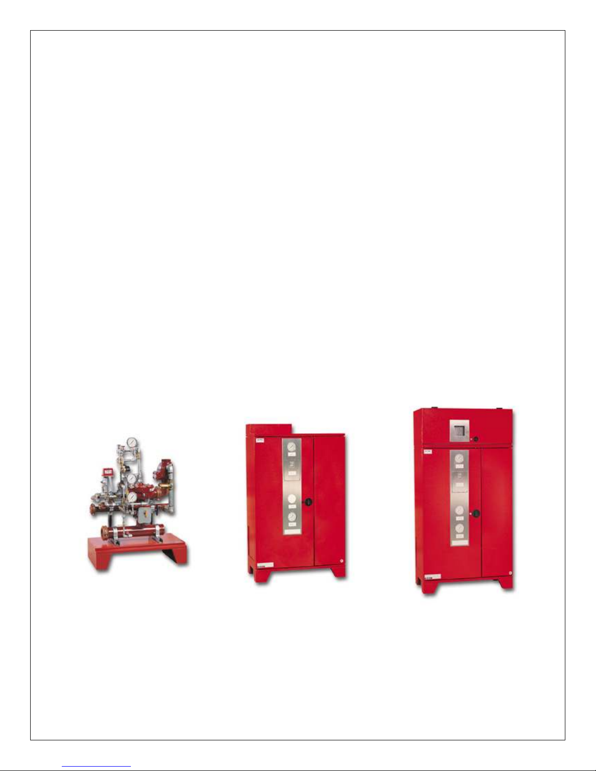
Advanced Integrated Fire Protection Systems
®
T
OTAL
Owner's Operation
P
and
AC
2
Maintenance Manual
D
ELUGE
September 2009
FM-086G-0-6F
Page 2

T
OTALPAC
2
T
OTALPAC
2 Integrated Fire Protection System
O
WNER'S OPERATION & MAINTENANCE MANUAL
FM-086G-0-6F
Manufactured by
Tel: (450) 437-3473 Toll free: (866) 347-3353
Web Site: http://www.fireflex.com - E-Mail:
FireFlex Systems Inc.
1935 Lionel-Bertrand Blvd
Boisbriand, QC (Canada) J7H 1N8
Fax: (450) 437-1930
Page 3

T
OTALPAC
T
OTALPAC
2 Integrated Fire Protection System
O
WNER'S OPERATION & MAINTENANCE MANUAL
Table of contents
Deluge
Description Form No
General ...................................................................................................................................... FM-086G-0-15
1- Applicable standards
2- Listings & Approvals
3- Environment
4- General description
5- Features
6- Configuration Description
7- Release systems
7a- Hydraulic Release
7b- Pneumatic Release
7c- Electric Release
Mechanical Section ................................................................................................................. FM-086G-0-24
1- Installation, Operation and Instruction
1.1- Installation
1.2- Preliminary inspection before placing the system in service
1.3- Placing the system in service
1.4- System operation
1.5- Emergency instructions
1.6- Placing system back in service
1.7- Inspections & tests
1.8- Maintenance
2- Hydraulic Release Trim Schematic
3- Pneumatic Release Trim Schematic
4- Electric Release Trim Schematic
2
Preaction Trim Option .......................................................................................................... FM-086G-0-46
1- Shut-off valve & sight glass
2- Fire department connection
3- Semi & Full flange option
Air Supply Section ...................................................................................................................FM-086G-0-43
1- Cabinet
2- Skid
Air supply option: Viking Dehydrator .................................................................................FM-086G-0-44
Air supply option: Viking Accelerator .................................................................................FM-086G-0-45
Controls Section ...................................................................................................................... FM-086G-0-29
1- With Control Panel
2- Without Control Panel
Continued on next page…
FM-086G-0-6F
Page 4

T
OTALPAC
2
T
OTALPAC
2 Integrated Fire Protection System
O
WNER'S OPERATION & MAINTENANCE MANUAL
Table of contents (cont'd)
Deluge
Description Form No
Programming Section .............................................................................................................. FM-086G-0-38
1- Remote controlled, Pneumatic Release
2- Remote controlled, Hydraulic Release
2- Remote controlled, Electric Release
4- Self-Contained Unit, Electric Release
System Design and Dimensional Data ..................................................................................FM-086G-0-48
1- Skid Unit
2- Remote controlled Unit
3- Self-Contained Unit
Limited Warranty ...................................................................................................................... FM-086G-0-11
FM-086G-0-6F
Page 5

T
OTALPAC
2 Integrated Fire Protection System
O
WNER'S OPERATION & MAINTENANCE MANUAL
T
OTALPAC
2
Copyright © 2008-2009
Reproduction or use, without express written permission from FireFlex Systems Inc, of any portion of this manual is prohibited.
While all reasonable efforts have been taken in the preparation of this manual to assure its accuracy, FireFlex Systems Inc
assumes no liability resulting from any errors or omissions in this manual, or from the use of the information contained herein.
T
OTALPAC
FireFlex Systems Inc. reserves the right to make changes to this manual and the data sheets herewith at any time, without prior
notification.
® is a registered trademark of FireFlex Systems Inc.
FireFlex Systems Inc
All Rights Reserved
.
FM-086G-0-6F
Page 6
T
OTALPAC
2
T
OTALPAC
2 Integrated Fire Protection System
O
WNER'S OPERATION & MAINTENANCE MANUAL
FM-086G-0-6F
TOTALPAC
Page 7

T
OTALPAC
General
2
T
OTALPAC
2 Integrated Fire Protection System
General Section - Deluge System
Page 1 of 4
1. Applicable Standards
The T
OTALPAC2
- NFPA-13 Sprinkler Systems;
- NFPA-15 Water Spray Fixed Systems;
- NFPA-16 Foam-Water Deluge and Foam-Water Spray
Systems;
- NFPA-72 Fire Alarm Systems.
Before the installation, the contractor installing the unit shall
be familiar with the following documents and standards:
- Applicable Local & State Building Codes
- Any additional requirements of the Local Authority
Having Jurisdiction.
2. Listings and Approvals
In addition to being fabricated under tight ISO-9001
manufacturing and quality control procedures, your
T
OTALPAC
recognized laboratories. Here is the list of Listings &
Approvals it meets:
- Underwriters Laboratories Inc. (UL): Deluge T
systems are UL Listed under "Special System Water
Control Valves - Assembled Units, category
# VKYL.EX4641" and "Assembled Units Certified for
Canada, Category # VKYL7.EX4641 (C-UL)".
- Factory Mutual Research <FM>: Deluge T
systems are FM Approved under the heading:
"Automatic Water Control Valves" when installed with
specific components.
California State Fire Marshal <CSFM>: Preaction
TotalPac2 systems are CSFM Approved under the
heading: Misc. Devices/Control Unit Accessories,
Listing No. 7300-0533:107.
- City of New York: Deluge TotalPac2 systems are
Approved under the Certificate of Approval # 6021.
(electric release only)
Note: Although most T
built units are sometimes supplied on request.
Components in these special units maintain their
individual Listings/Approvals but the units are not Listed
as an assembled unit.
complies with the following standards:
2 Unit has also been tested and approved by
OTALPAC
OTALPAC
OTALPAC
2 units are Listed, custom
3. Environment
T
OTALPAC
location. Verify that all equipment is properly heated and
protected to prevent freezing and physical damage.
The unit and it's components must be kept free of foreign
matter, freezing conditions, corrosive atmospheres,
contaminated water supplies, and any condition that
could impair its operation or damage the components.
The frequency of the inspections and maintenance will
vary depending on these environmental conditions. The
owner is responsible for maintaining the fire protection
system and devices in proper operating condition.
Refer to MECHANICAL DESCRIPTION for maintenance
instructions.
2
2
2 units shall be installed in a dry and clean
CAUTION ! Any unauthorized modification or addition
made on-site to a factory built Listed Unit will void this
Listing. Such modifications or additions may void the
unit's warranty as well. Consult your nearest FireFlex
Systems Authorized Distributor before proceeding with
such modifications or additions.
FM-086G-0-15E
Page 8

Page 2 of 4
T
OTALPAC
2 Integrated Fire Protection System
T
OTALPAC
2
General Section - Deluge System
4. General Description
There are several types of deluge systems, but all of
them use open type sprinklers and / or spray nozzles in
the sprinkler piping which totally flood an area with
pressurized water. A detection network is used in parallel
with the open type sprinkler / nozzles system. This
network may be hydraulic, pneumatic or electric and may
be actuated by manual, fixed temperature, rate-of-rise
temperature, smoke or other means. When the detection
system operates it gives an alarm and activates the
deluge valve. Because deluge systems are often used in
extra-hazard occupancies, electrical and pneumatic
detection systems are by far the most common.
The T
OTALPAC
FireFlex Systems Inc. consists of a deluge system trim
totally pre-assembled, pre-wired and factory tested. All
electrical and mechanical components of the system are
contained in one single unit.
Note: Skid units include the trim components only and
must be wired by the installing contractor.
The only connections required for installation are the
water supply inlet, water discharge outlet, main drain, and
the electrical detection and alarm connections. The
discharge outlet is connected to a fixed piping system of
open sprinklers and or nozzles. Water is the
extinguishing agent.
Deluge systems are usually supervised. The T
system is supervised in order to monitor its integrity. The
electrical detectors and associated wiring are also
supervised.
The most common applications are protection of extrahazard occupancies by creating a fire buffer zone or by
cooling surfaces to prevent deformation or structural
collapse. Examples: storage or process areas containing
substances having a low flash point; areas in which fire
may spread rapidly; tanks containing combustible
solutions, transformers, equipment pits or product
handling systems.
Systems should be designed by qualified fire-protection
engineers in conjunction with the appropriate Authority
Having Jurisdiction.
2 integrated fire protection system by
OTALPAC
5. Features
Your T
OTALPAC
available on the market now and has been manufactured by
the company that has introduced and developed the concept
of integrated fire protection systems in the market.
Main features are:
- Trouble free design for safe and easy application
- Available in 5 sizes from 1½" to 6" diameter
- Uses the Viking Deluge Valve
- Available and Listed both with or without Integrated Control
Panel
- Compact, aesthetic and easy to move
- User-friendly standardized owner's manual with every unit
- Unique serial number on every unit
- Uses only UL, C-UL Listed and FM Approved components
- Designed in accordance with NFPA Standards
- Trim is fully assembled and tested at the factory
- Water supply and drain connections on both sides,
available both with grooved end or flanged fittings
- Sturdy 14 Gauge steel cabinet or skid painted fire red with
oven baked polyester powder on phosphate base
- Textured rust proof finish
- Neoprene gasket on all doors to eliminate vibrations
- Easily removable doors for ease of access
- Key-alike locks on all cabinet doors
2
- Manufactured under ISO-9001 quality control procedures.
2 unit is superior than many other products
Note: Each T
Serial Number. This number is located on a sticker
inside the main door panel and is used to maintain a
record in our computerized data base. Have this Serial
Number handy when calling for information on your unit
(format is TOT##### or TOTS#### for skids).
FM-086G-0-15E
OTALPAC
2 Unit is identified with it's unique
Page 9

T
OTALPAC
2
T
OTALPAC
2 Integrated Fire Protection System
General Section - Deluge System
Page 3 of 4
6. Configurations Description
A Deluge system is a fixed fire-protection system which
totally floods an area with pressurized water through a
system piping of open nozzles or sprinklers. The system
piping is empty until the Deluge Valve is activated by a
hydraulic, pneumatic, electric or manual release system.
T
OTALPAC
Trim™ using Deluge Valves Model E-3 for 1½" (40 mm)
diameter (Model E-4 is the Halar® Coated version for use in
corrosive environments) or Model E-1 for 2" (50 mm)
diameter and up (Model E-2 is the Halar® Coated version for
use in corrosive environments).
All the valves are rated up to a maximum of 250 psi WWP
(1724 kPa) and are available in the following diameters:
T
OTALPAC
Deluge Valves. Units with flange–flange Deluge Valves are
also available on request.
2 Deluge systems are built around the Viking EZ-
1½" (40 mm)
3" (80 mm)
6" (150 mm)
2 Deluge systems are supplied with flange–groove
2" (50 mm)
4" (100 mm)
7. Release Systems
7a
Hydraulic Release.
systems require a hydraulic release system, equipped with
fixed temperature releases, and/or pilot heads.
In fire conditions, operation of a releasing device on the
hydraulic release system opens the Deluge Valve, allowing
water to enter the system piping. Water will flow from any
open sprinklers and/or spray nozzles on the system.
7b
Pneumatic Release. Pneumatically controlled deluge
systems require a pneumatic release system, equipped with
fixed temperature releases, and/or pilot heads.
Release trim, for pneumatically controlled deluge systems
utilize a Pneumatic Actuator (F3) normally held closed by
pressure maintained in the pneumatic release system.
Note: The air supply for the pneumatic release piping
system must be provided by the contractor and installed
outside the T
restricted to ensure that the automatic air supply cannot
replace air as fast as it escapes when a releasing device or
sprinkler operates. It is also recommended to provide
Inspectors Test Connections on both the release system
and the sprinkler system.
In fire conditions, operation of the pneumatic release system
opens the Deluge Valve, allowing water to enter the system
piping. Water will flow from any open sprinklers and/or spray
nozzles on the system.
OTALPAC
Hydraulic
2 unit. The air supply must be
ally controlled Deluge
7c
Electric Release. Electrically controlled deluge systems
require an electric Solenoid Valve (F1) controlled by an
approved System Control Panel with compatible detection
devices (if provided with this system, see Controls Section for
details).
In fire condition, when the detection condition is satisfied the
system Control Panel energizes the Solenoid Valve (F.1)
open, causing the Deluge Valve (A1) to open allowing water
to enter the system piping. Water will flow from any open
sprinklers and/or spray nozzles on the system.
FM-086G-0-15E
Page 10

Page 4 of 4
T
OTALPAC
2 Integrated Fire Protection System
General Section - Deluge System
T
OTALPAC
2
This page was intentionally left blank
FM-086G-0-15E
Page 11

TOTALPAC2 Page 1 of 12
TOTALPAC2 Integrated Fire Protection Systems
Mechanical Section - Deluge System
1- Installation, Operations & instructions
See Trim Schematic at the end of the current Section
1.1 Installation
1. Install the TOTALPAC2 unit and connect the system
according to instruction manual and technical data
supplied.
Note: The drain collector shall be connected to an open
drain. Do not restrict or reduce drain piping.
2. Install the automatic sprinkler piping, releasing piping
detection and signaling circuits (if applicable) in
accordance with applicable standards.
3. Conform to local municipal or other codes regarding
installations of fire protection systems.
4. Perform preliminary inspection outlined in paragraph 1.2
prior to putting system in service.
5. Put the system into operation Place the system in service
as outlined in paragraph 1.3.
6. Perform the annual inspection sequence and test each
detector and alarm unit.
7. If the system does not operate as it should, make the
necessary corrections according to manuals issued or
consult your distributor or FireFlex Systems Inc.
8. Make sure that building owner or a delegated
representative has received instructions regarding the
operation of the system.
1.2 Preliminary inspection before placing the
system in service
1. Open door to mechanical section. Main Water Supply
Control Valve (D1) should be CLOSED. Priming
valve (B1) must be CLOSED. Air supply if applicable
must be CLOSED (see AIR SUPPLY SECTION). Flow
Test Valve (B6) and main drain valve (D3) must be
CLOSED. Alarm test valve (B5) must be CLOSED. All
gauges (B11, B12 and E3) should show 0 psi pressure.
2. Connect all detection and alarm audible devices
according to electrical schematics (see TBA field wiring
diagram in PROGRAMMING SECTION).
3. If applicable, connect the AC power for the control
panel (L1) on a separate breaker in the electric
distribution panel (see TBB field wiring diagram in
PROGRAMMING SECTION).
Note: Do not use these circuit breakers for other parallel
applications. If necessary, equip each circuit breaker with
a security seal in order to avoid accidental closing.
4. After the Deluge Valve is set, operation of the Deluge
valve requires the release of priming water from the
priming chamber. This may be by automatic or manual
operation of one of the release systems described
above. For specific trim arrangement, refer to the
MECHANICAL TRIM DESCRIPTION.
Note: Electric Release: Solenoid valves, system control
panels and electrical detectors must be compatible.
Consult the CONTROLS SECTION for compatibility charts.
T
OTALPAC2 Units must be installed in an area not subject
to freezing temperatures or physical damage.
FM-086G-0-24D
Page 12

Page 2 of 12 TOTALPAC2
TOTALPAC2 Integrated Fire Protection Systems
Mechanical Section - Deluge System
1.3 Placing the system in service:
(Refer to MECHANICAL TRIM DESCRIPTION and TRIM
SCHEMATIC)
1. Verify the following:
a) The system Main Water Supply Control Valve (D1) is
CLOSED.
b) The system has been properly drained.
c) Flow Test Valve (B6) is OPEN.
d) The Emergency Release Valve (B10) is CLOSED.
e) The system water supply piping is pr essurized up to
the CLOSED Main Water Supply Valve (D1) and the
priming line is pressurized up to the CLOSED
Priming Valve (B1).
2. Verify that all releasing devices are set and that any
Inspector's test Valve and/or auxiliary drain valves are
CLOSED.
a) OPEN Priming Valve (B1).
3. OPEN Main Drain Valve (D3).
4. PARTIALLY OPEN Main Water Supply Control Valve
(D1).
5. When full flow develops from the Flo w Test Valve (B6),
CLOSE the Flow Test Valve.
a) Verify that there is no flow from the open Main Drain
Valve (D3).
6. CLOSE Main Drain Valve (D3).
7. FULLY OPEN and secure the Main Water Supply
Control Valve (D1).
8. Verify that the Alarm Test Valve (B5) is CLOSED and
that all other valves are in their "normal" operating
position (Refer to TRIM SCHEMATIC for details).
9. Depress the plunger of the Drip Check Valve (B7). No
water should flow from the Drip Check when the plunger
is pushed.
10. Check and repair any leaks.
11. On new installations, systems that have been placed out
of service, or where new equipment has been installed,
trip test system to verify that all equipment functions
properly. Refer to MAINTENANCE – ANNUALLY for
instructions.
CAUTION ! Performing a trip test results in operation of the
Deluge/Flow Control Valve. Water will flow into the
sprinkler piping. Take necessary precautions to prevent
damage.
12. After completing the trip test, perform MAINTENANCE –
SEMI-ANNUALLY.
Note: When a valve has been removed from service and is
subject to freezing or will be out of service for an extended
period of time, all water must be removed from the priming
chamber, trim piping, water supply piping and any other
trapped areas.
13. Notify the Authority Having Jurisdiction, remote station
alarm monitors, and those in the affected area that the
system is in service.
Important Settings
Release Piping Pressures.
f Deluge Systems with Pneumatic Release
(also refer to Table 1 below):
.a Provide a minimum 30 PSI (207 kPA) pneumatic
pressure to the pneumatic release system and
Pneumatic Actuator (F3) for system water pressures of
175 psi (1 207 kPa) or less.
.b For system water pressures above 175 psi (1 207 kPa)
and up to 250 psi (1 724 kPa), provide a minimum of 50
psi (345 kPa) pneumatic pressure to the pneumatic
release system and Pneumatic Actuator (F3).
.c Set release system Air Pressure Supervisory Switch
(E3) to activate at 25 psi (172 kPa) on pressure drop for
system water pressures of 175 psi (1 207 kPa) or less.
For system water pressure above 175 psi up to a
maximum of 250 psi (1 724 kPa), set the Air Pressure
Supervisory Switch (E4) to activate at 45 psi (310 kPa)
on pressure drop. Air Pressure Supervisory Switch
(E4) is factory wired to activate an alarm to signal a lo w
air pressure condition (see AIR OPTION SECTION for
additional details).
Note: The air supply for the pneumatic release piping
system must be provided by the contractor and installed
outside the TOTALPAC2 unit. The air supply must be
restricted to ensure that the automatic air supply cannot
replace air as fast as it escapes when a releasing device or
sprinkler operates. It is also recommended to provide
Inspectors Test Connections on the release system.
Table 1: Settings for Pneumatic Release Systems.
WATER SUPPLY PRESSURES
DEVICE
Air Maintenance
Device (E5)
Release System
Pressure Supervisory
Switch (E4)
Nitrogen Supply
Regulator
Nitrogen Back-Up
Pressure Supervisory
Switch (E4)
Up to 175 psi
(1 207 kPa)
SET TO MAINTAIN
30 PSI (207 kPa) 50 PSI (345 kPa)
25 PSI (172 kPa)
On Pressure Drop
35 PSI (242 kPa) 55 PSI (379 kPa)
30 PSI (207 kPa)
On Pressure Drop
.d Alarm Pressure Switch (C1) should activate when
pressurized to 4 to 8 psi (27 to 55 kPa) on pressure
rise. Alarm Pressure Switch (C1) is factory wired to
activate the water flow alarm.
175 psi (1 207 kPa)
to 250 psi (1724 kPa)
SET TO MAINTAIN
45 PSI (310 kPa)
On Pressure Drop
50 PSI (345 kPa)
On Pressure Drop
FM-086G-0-24D
Page 13

TOTALPAC2 Page 3 of 12
TOTALPAC2 Integrated Fire Protection Systems
Mechanical Section - Deluge System
f Deluge systems with Hydraulic Release:
.a Alarm Pressure Switch (C1) should activate when
pressurized to 4 to 8 psi (27 to 55 kPa) on pressure
rise. Alarm Pressure Switch (C1) is factory wired to
activate the water flow alarm.
.b Release system piping must not exceed the maximum
elevation allowed for hydraulic release piping above
the Deluge Valve. Refer to technical Data for the
hydraulically operated Deluge Valve used.
.c The water supply to the hydraulic release system must
include a restricted orifice (B3) to ensure that the
priming line cannot replace hydraulic pressure as fast
as it escapes when a releasing device operates.
1.4 System Operation
1.4.1 In the SET condition:
System water supply pressure enters the priming chamber of
the Deluge Valve (A1) through the priming line which
includes a normally open priming valve (B1), strainer (B2),
restricted orifice (B3) and spring loaded check valve (B4) and
the normally open P.S.O.V. (B9).
f Hydraulic Release System: In the SET condition, water
supply pressure is trapped in the priming chamber and
hydraulic release piping by a spring loaded check valve
(B4) and closed releasing devices. The pr essure in the
priming chamber holds the Deluge Valve clapp er closed,
keeping the outlet chamber and system piping dry.
f Pneumatic release System: In the SET condition, water
supply pressure is trapped in the priming chamber b y a
spring loaded check valve (B4) and Pneumatic Actuator
(F3). Pneumatic Actuator is held closed by pressure
maintained in the pneumatic release system. The
pressure in the priming chamber holds the Deluge Valve
clapper closed, keeping the outlet chamber and system
piping dry.
f Electric Release System: System water supply pressure
enters the priming chamber of the Deluge Valve. In the
SET condition, water supply pressure is trapped in the
priming chamber by a spring loaded check valve (B4) and
normally closed Solenoid valve (F1). The pressure in the
priming chamber holds the Deluge Valve clapp er closed,
keeping the outlet chamber and system piping dry.
1.4.2 In a fire condition:
f Hydraulic Release System: When a releasing device
operates, water pressure in the hydraulic release system
escapes.
f Pneumatic release System: When a releasing device
operates, pressure in the pneumatic release system
escapes causing the Pneumatic Actuator (F3) to open.
f Electric Release System: When the detection system
operates, system Control Panel activates an alarm and
energizes normally closed Solenoid valve (F1) to open.
Pressure is released from the priming chamber to the open
drain manifold faster than it is supplied through the restricte d
orifice (B3). The Deluge Valve clapper opens to allow water
to flow into the system piping and alarm devices, causing the
optional Water Motor Alarm (C2) and water flow alarms
connected to the Alarm Pressure Switch (C1) to activate
Water will flow from all the open sprinklers and/or nozzles in
the system.
When the deluge valve operates, the sensing end of the
PSOV (B9) is pressurized, causing the PSOV to close.
When the PSOV closes, it shuts off the flow of the priming
water pressure to the priming chamber, preventing the
Deluge Valve (A1) from resetting, even if the open releasing
devices close. The Deluge Valve can only be reset after the
system is taken out of service, and the outlet chamber of the
deluge valve and associated trim piping is de pressurized an d
drained.
1.4.3 Manual operation:
Anytime the handle of the Emergency Release (B10) is
pulled, pressure is released from the priming chamber;
Deluge Valve (A1) will open. Water will flow from any open
sprinklers and/or other opening in the sprinkler piping and
alarm devices (C1 & C2) will operate.
1.4.4 Trouble conditions:
f Hydraulic Release System: If the release system operates
due to mechanical damage or malfunction, the Deluge
Valve will open and water will flow from any open
sprinklers and/or other opening in the sprinkler piping.
f Pneumatic Release Systems: In the event of an air
supply failure and slow leakage of air from the pneumatic
release system, alarms connected to Air Supervisory
Switch (E3) will signal a low air pressure condition.
Failure to restore air supply to the pneumatic release
system will result in the operation of the Pneumatic
Actuator (F3). Pressure is released from the priming
chamber faster than it is supplied through the Restricted
Orifice (B3).
f Electric Release controlled Deluge Systems: If the release
system operates due to mechanical damage or
malfunction, the Deluge Valve (A1) will open and water
will flow from any open sprinklers and/or other openin g in
the sprinkler piping.
FM-086G-0-24D
Page 14

Page 4 of 12 TOTALPAC2
TOTALPAC2 Integrated Fire Protection Systems
Mechanical Section - Deluge System
1.5 Emergency Instructions
(Refer to piping diagram provided)
To take system Out of Service:
Warning ! Placing a control valve or detection system out of
service may eliminate the Fire Protection capabilities of the
system. Prior to proceeding, notify all Authorities Having
Jurisdiction. Consideration should be given to employ a fire
patrol in the affected areas.
Sprinkler systems that have been subjected to a fire must
be returned to service as soon as possible. The entire
system must be inspected for damage, and repaired or
replaced as necessary. After a fire, verify that the fire is
OUT and that placing the system out of service has been
authorized by the appropriate Authority Having Jurisdiction.
.1 Close Water Supply Control Valve (D1).
.2 Open system Main Drain Valve (D3).
.3 Silence alarms (if provided, refer to CONTROL
PANEL SECTION for additional details).
Note: Electric alarms controlled by a pressure switch
installed in the ½" (15mm) NPT connection (C2) for a Noninterruptible Alarm Pressure Switch cannot be shut-off until
the Deluge Valve (A1) is reset or taken out of service.
.4 For Pneumatic Release Systems, shut-off the air
supply (refer to AIR SUPPLY SECTION).
.5 Close Priming Valve (B1) (optional).
.6 Replace any detectors, pilot heads or fixed
temperature releases that have operated.
.a To drain the hydraulic release piping, pull the handle
of the Emergency Release (B11).
.7 Replace any sprinkl ers and/or spray nozzles that have
been damaged, or have been exposed to fire
conditions.
.8 Perform all maintenance procedures recommended in
MAINTENANCE, describing individual components of
the system that has operated.
.9 Return the system to service as soon as poss ible.
1.6 Placing the system back in service after
operation:
(refer to TRIM SCHEMATIC)
.1 Verify that the system has been properly drained (in
cycling systems, System Main Water Supply Control
Valve (D1) should be CLOSED). System Main Drain
Valve (D3) should be OPEN. Verify that Emergency
Release (B10) is CLOSED. Priming Valve (B1) should
be CLOSED except for the electrical release system
where is should be OPEN.
.2 f Hydraulic Release System: Verify that the
Inspectors Test Valve and any auxiliary drains are
closed.
f Pneumatic Release System: Restore pneumatic
pressure. Maintain 30PSI (207 kPa) or 50 PSI (345
kPa) as required by the Pneumatic Actuator (F3) and
refer to TABLE 1 above for pressures.
f Electric Release System: Reset the control panel.
Solenoid valve (F1) should close. Flow from the
solenoid valve to the drain manifold should stop.
.3 Open Priming Valve (B1) (except for electric release
system which is already open).
f Hydraulic Release System: Verify that the pressure
on Priming Water Pressure Gauge (B11) indicates that
the priming chamber is pressurized with system Water
Supply Pressure (B12).
.4 Open Flow Test Valve (B6).
.5 Partially open Main Water Supply Valve (D1).
.6 When full flow develops from Flow Test Valve (B6),
close the Flow Test Valve. Verify that there is no flow
from the System Main Drain Valve (D3).
.7 Close the System Main Drain Valve (D3).
.8 Fully open and secure the Main Water Supply Control
Valve (D1).
.9 Verify that the Alarm Test Valve (B5) and all other
valves are at their NORMAL operating position.
.10 Depress the plunger of Drip Check (B7). No water
should flow from the Drip Check when the plunger is
pushed.
FM-086G-0-24D
Page 15

TOTALPAC2 Page 5 of 12
TOTALPAC2 Integrated Fire Protection Systems
Mechanical Section - Deluge System
1.7 Inspections & Tests
It is imperative that the system be inspected on a regular
basis. Refer to INSPECTIONS and TESTS recommended
in current Viking technical Data describing individual
components of the Viking Deluge System used.
The frequency of the inspections may vary due to
contaminated water supplies, corrosive or humid
atmospheres as well as the condition of the air s uppl y to the
system. In addition to the instructions herewith, local
Authority Having Jurisdiction may have additional
maintenance, testing and inspection requirements which
must be followed.
Warning ! Any system maintenance which involves placing
a control valve or detection system out of service may
eliminate the fire protection capabilities of that system.
Prior to proceeding, notify all Authorities Having
Jurisdiction. Consideration should be given to employm ent
of a fire patrol in the affected areas.
1.7.1 Pneumatic Release System Low Air Pressure
Alarm Test:
Quarterly testing of low air alarms is recommended.
To test Pneumatic Release System "Low Supervisory
Air" Alarm:
1. To prevent operation of the Deluge Valv e and filling the
system with water during the test, close the Main Water
Supply Control Valve (D1).
2. Fully open the releasing system Inspectors Test Valve
to simulate operation of a releasing device.
3. Verify that low air alarms operate within an acceptable
time period and continue without interruption.
4. Close the Inspectors Test Valve.
5. Close the Priming Valve (B1).
6. Establish recommended pneumatic supervisory
pressure to be maintained.
7. Alarms should stop.
8. Open the Priming Valve (B1).
When testing is complete, return the system to service
following steps 1 through 8 below.
CAUTION ! This procedure applies only when done in
conjunction with "Low Air" Alarm testing described above.
1. Verify that the pressure indicated on Priming Pressure
Water Gauge (B11) indicates that the priming chamber
is pressurized with System Water Supply Pressure
(B12).
2. Depress the plunger of Drip Check (B7). No water
should flow from the Drip Check when the plunger is
pushed.
3. Open Flow Test Valve (B6).
4. Partially open Main Water Supply Control Valve (D1).
5. When full flow develops from Flow Test Valve (B6),
close the Flow Test Valve.
6. Fully open and secure the Main Water Supply Control
Valve (D1).
7. Verify that the Alarm Test Valve (B5) and all other
valves are in their NORMAL operating position.
8. Depress the plunger of the Drip Check (B7). No water
should flow from the Drip Check when the plunger is
pushed.
1.7.2 Full Flow Trip test:
Performance of a Trip Test is recommended annually
during warm weather. Consider coordinating this test with
operation testing of the detectors.
CAUTION ! Performing this test will cause the Deluge Valve
to open. Water will flow into the sprinkler pipin g and from
any open sprinkler and/or nozzles unless the Optional
Shut-Off Valve is installed and closed prior to the test.
Take necessary precautions to prevent damage.
To test the operation of the hydraulically released
Deluge system:
1. Fully open the hydraulic release system Inspectors
Test Valve to simulate operation of a releasing device.
2. The Deluge Valve should open.
a. Water flow alarms should operate.
b. Water should fill the sprinkler piping and fl ow from
any open sprinklers and/or nozzles.
3. Close Inspectors Test Valve.
When testing is complete, return the system to service:
1. Close Water Supply Valve (D1).
2. Open System Main Drain Valve (D3).
3. Perform steps 1 through 10 of section 1.3 Placing the
system in service.
1.7.3 Drain Test:
A main drain test shall be conducted to determine whether
there has been a change in the condition of the water supply
piping and control valves.
Test procedure:
1. Record the pressure indicated by the supply water gauge.
2. Close the alarm control valve (if applicable)
3. Fully open the flow test valve.
4. Record residual pressure.
5. Close the flow test valve slowly.
6. Record the time taken for supply water pressure to return
to the original pressure.
7. Open the alarm control valve (if applicable)
FM-086G-0-24D
Page 16

Page 6 of 12 TOTALPAC2
TOTALPAC2 Integrated Fire Protection Systems
Mechanical Section - Deluge System
1.8 MAINTENANCE
Note: The owner is responsible for maintaining the fire
protection system and devices in proper operating
condition.
Refer to MAINTENANCE INSTRUCTIONS provided in
current Viking Technical Data describing individual
components of the Viking Preaction System used.
Where difficulty in performance is experienced, the valve
manufacturer or his authorized representative shall be
contacted if any field adjustment is to be made.
The following requirements are based upon NFPA-25:
Records.
Records of inspections, tests, and maintenance of the
system and its components shall be made available to the
authority having jurisdiction upon request. Typical records
include, but are not limited to, valve inspections; flow, drain,
and pump tests; and trip tests of dry pipe, deluge, and
preaction valves.
Acceptance test records should be retained for the life of the
system or its special components. Subsequent test records
should be retained for a period of 1 ye ar after the next test.
The comparison determines deterioration of system
performance or condition and the need for further testing or
maintenance.
Monthly:
.1 Inspection of gauges (water supply and system
pressure) to ensure good condition and normal water
supply pressure.
.2 Control valve shall be externally inspected. The valv e
inspection shall verify the following:
.a The gauges indicate that normal supply water
pressure is being maintained.
.b The valve is free of physical damag e.
.c All valves are in the appropriate open or closed
position.
.d There is no leakage from the alarm drains.
Quarterly:
.1 Alarm Device (pressure or flow switch). (Testing by
opening the inspector's test connection).
.2 Full flow trip test: (isolation valve perfect for special
site condition such as freezing condition) to determine
if change in water supply or control valve position.
Semi-Annually:
.1 Valve supervis ory switch shall be tested to verify the
operation of the switch upon movement of the hand
wheel.
Annually:
.1 Manual Pull station test
.2 Full trip test: Isolation valve perfect for special site
condition such as freezing condition .
.3 Deluge system shall also be tested for flo w pattern.
.4 Record indicating the date of the last trip, tripping time
and name of organization conducting the te st shall be
maintain at a location available for review by the
Authority having Jurisdiction.
Every 5 years:
.1 Test on gauge (gauge precision required: less than
3% of the full scale)
.2 Test on control valves operation.
.3 Main drain test.
FM-086G-0-24D
Page 17

TOTALPAC2 Page 7 of 12
TOTALPAC2 Integrated Fire Protection Systems
Mechanical Section - Deluge System
2- System with Hydraulic Release
1. Description
The T
OTALPAC2 System with the Viking Deluge Trim utilizes
a Viking Deluge valve (A1) to control water flow into system
piping equipped with open sprinklers and/or spray nozzles.
The system piping remains empty until t he Deluge Valve is
activated by operation of the release system.
Hydraulically controlled deluge systems require a hydraulic
release system, equipped with thermostatic (rate-of-rise)
releases, and/or fixed temperature releases and/or pilot
heads.
Deluge systems are designed so the Deluge valve will
open when a detector on the hydraulic release system
operates. When the Deluge Valve opens, water will flow
into the sprinkler piping and out of any open sprinklers,
open spray nozzles and any opening on the system.
Deluge TOTALPAC2 Systems are commonly used where it is
desirable to simultaneously spray water from all open
sprinklers and/or spray nozzles on the system when the
system operates.
2. Normal condition
1. Valves
a) Main water supply control valve (D1) is OPEN.
b) All upstream water supply valves are OPEN.
c) Priming valve (B1) is OPEN.
d) Flow test valve (B6) is CLOSED.
e) System main drain valve (D3) is CLOSED.
f) Alarm test valve (B5) is CLOSED
g) Manual emergency release valve (B10) is CLOSED
(handle in vertical position).
h) All gauge valves are OPEN.
2. Gauges
a) Water supply (B12) - at water supply pressure
b) Priming chamber (B11) - should be equal to, or
higher than, water supply pressure (B12).
3. Pressure switch
a) Alarm switch (C1) - should activate when pressurized
higher than 5 psi.
4. Optional equipment (see OPTIONAL EQUIPMENT
SECTION)
a) Shut-off valve (D4) is OPEN.
REFER TO TRIM SCHEMATIC ON NEXT PAGE.
FM-086G-0-24D
Page 18
Page 8 of 12 TOTALPAC2
TOTALPAC2 Integrated Fire Protection Systems
Mechanical Section - Deluge System
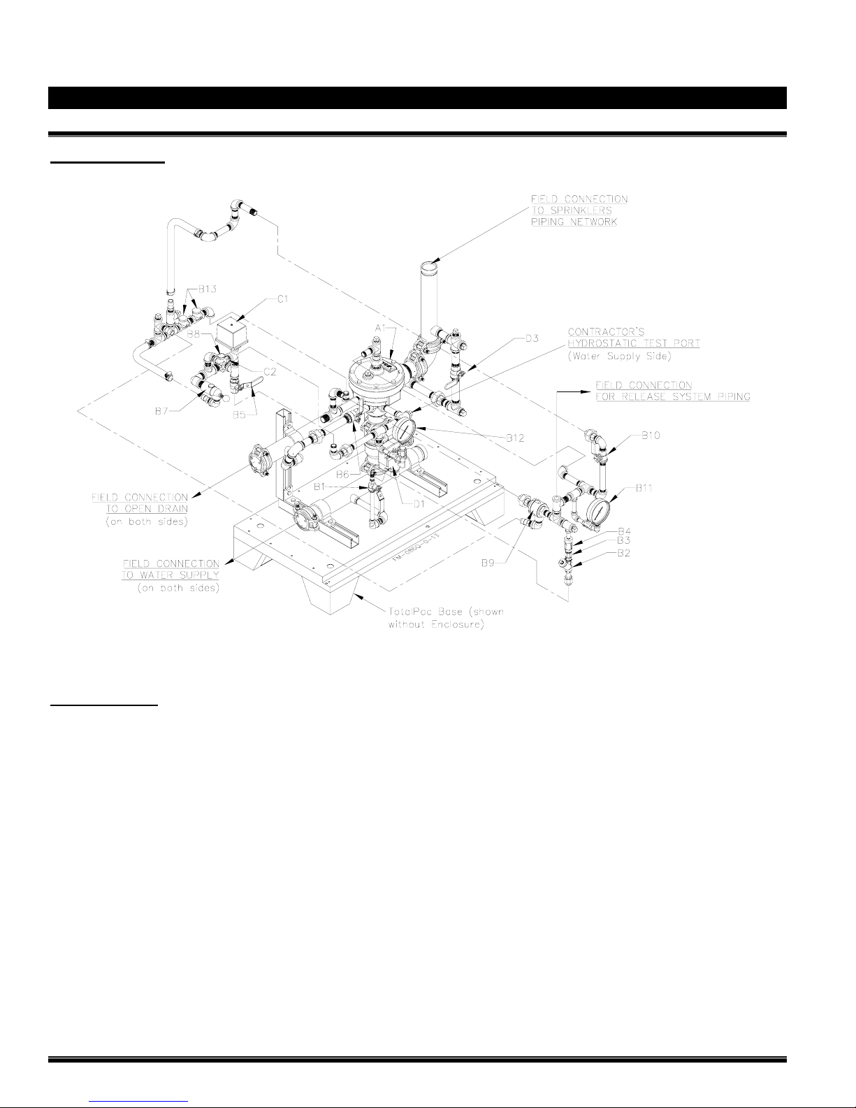
Trim Schematic: Deluge System with Hydraulic
Release
Trim Components:
A. Valve:
A1 Deluge valve
B. Deluge Valve Trim:
B1 Priming valve
B2 Strainer
B3 1/16" Restricted orifice
B4 Spring loaded check valve
B5 Alarm test valve
B6 Flow test valve
B7 Drip check valve
B8 Drain check valve
B9 Pressure operated relief valve (PORV)
B10 Emergency release valve
B11 Priming pressure water gauge & valve
B12 Water supply pressure gauge & valve
B13 Clapper check valve
FM-086G-0-24D
C. Water Flow Alarm Equipment:
C1 Alarm pressure switch
C2 Connection to water motor gong (strainer supplied
by contractor)
D. Valve:
D1 Water supply control valve
D3 Main drain valve
Page 19

TOTALPAC2 Page 9 of 12
TOTALPAC2 Integrated Fire Protection Systems
Mechanical Section - Deluge System
3- System with Pneumatic Release
1. Description
The T
OTALPAC2 System with the Viking Deluge Trim utilizes
a Viking Deluge valve (A1) to control water flow into system
piping equipped with open sprinklers and/or spray nozzles.
The system piping remains empty until t he Deluge Valve is
activated by operation of the release system.
Pneumatically controlled deluge systems require a pneumatic
release system, equipped with fixed temperature releases
and/or pilot heads. Release trim, for pneumatically controlled
deluge systems utilize a Pneumatic Actuator (F3) normally
held closed by pressure maintained in the pn eumatic release
system.
Deluge systems are designed so the Deluge valve will
open when a detector on the pneumatic release system
operates. When the Deluge Valve opens, water will flow
into the sprinkler piping and out of sprinklers and any
opening on the system.
Note: The air supply for the pneumatic release piping
system must be provided by the contractor and installed
outside the TOTALPAC2 cabinet. The air supply must be
restricted to ensure that the automatic air supply cannot
replace air as fast as it escapes when a releasi ng device
operates. It is also recommended to provide Inspectors
Test Connections on both the release system and the
sprinkler system.
Deluge T
desirable to simultaneously spray water from all open
sprinklers and/or spray nozzles on the system when the
system operates.
OTALPAC2 Systems are commonly used where it is
2. Normal condition
1. Valves
a) Main water supply control valve (D1) is OPEN.
b) All upstream water supply valves are OPEN.
c) Priming valve (B1) is OPEN.
d) Flow test valve (B6) is CLOSED.
e) System main drain valve (D3) is CLOSED.
f) Alarm test valve (B5) is CLOSED
g) Manual emergency release valve (B10) is CLOSED
(handle in vertical position).
h) All gauge valves are OPEN.
2. Gauges
a) Water supply (B12) - at water supply pressure
b) Priming chamber (B11) - should be equal to, or
higher than, water supply pressure (B12).
c) Release system air pressure (E3) and Pneumatic
Actuator (F4) – See table 1 below.
3. Pressure switch
a) Alarm switch (C1) - should activate when pressurized
higher than 5 psi (35 kPa).
b) Release system low air pressure switch (E4) – See
Table 1 below.
4. Optional equipment (see OPTIONAL EQUIPMENT
SECTION)
a) Shut-off valve (D4) is OPEN.
Table 1: Pressure Settings
DEVICE
Release System Air
Pressure Gauge (E3)
Pneumatic Actuator
Pressure Gauge (F4)
Low Air Supervisory
Pressure Switch (E4)
REFER TO TRIM SCHEMATIC ON NEXT PAGE.
WATER SUPPLY PRESSURES
Up to 175 psi
(1 207 kPa)
35 PSI (241 kPa) 55 PSI (380 kPa)
35 PSI (241 kPa) 55 PSI (380 kPa)
25 PSI (173 kPa) 45 PSI (311 kPa)
175 psi (1 207 kPa)
to 250 psi (1724 kPa)
FM-086G-0-24D
Page 20
Page 10 of 12 TOTALPAC2
TOTALPAC2 Integrated Fire Protection Systems
Mechanical Section - Deluge System
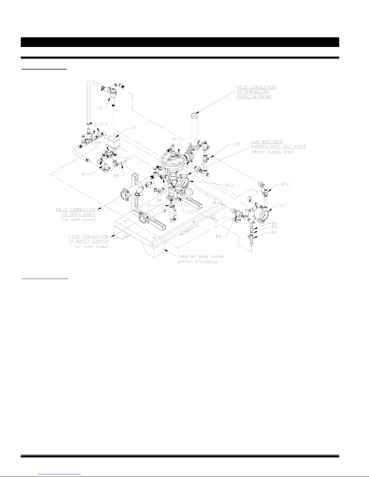
Trim Schematic: System with Pneumatic release
Trim Components:
A. Valve:
A1 Deluge valve
B. Deluge Valve Trim:
B1 Priming valve
B2 Strainer
B3 1/16" Restricted orifice
B4 Spring loaded check valve
B5 Alarm test valve
B6 Flow test valve
B7 Drip check valve
B8 Drain check valve
B9 Pressure operated relief valve (PORV)
B10 Emergency release valve
B11 Priming pressure water gauge & valve
B12 Water supply pressure gauge & valve
B13 Clapper check valve
B14 N/A
C. Water Flow Alarm Equipment:
C1 Alarm pressure switch
C2 Connection to water motor gong (strainer supplied
by contractor)
D. Valve:
D1 Water supply control valve
D3 Main drain valve
E. Supervisory Air Supply:
(See AIR SUPPLY SECTION for additional details)
F. Release System:
F3 Pneumatic actuator
FM-086G-0-24D
Page 21

TOTALPAC2 Page 11 of 12
TOTALPAC2 Integrated Fire Protection Systems
Mechanical Section - Deluge System
4- Deluge System with Electric Release
1. Description
The T
OTALPAC2 System with the Viking Deluge Trim utilizes
a Viking Deluge valve (A1) to control water flow into system
piping equipped with open sprinklers and/or spray nozzles.
The system piping remains empty until t he Deluge Valve is
activated by operation of the release system.
Electrically controlled deluge systems require an electric
Solenoid valve (F1) controlled by an approved System
Control Panel with compatible detection system. In fire
conditions, when the detection system operates, System
Control Panel energizes the Solenoid Valve (F1) open,
causing Deluge Valve (A1) to open and allowing water to
enter the system piping. Water will flow from any open
sprinklers and/or spray nozzles on the system.
Deluge systems are designed so the Deluge valve will
open when a detector on the electric release system
operates. When the Deluge Valve opens, water will flow
into the sprinkler piping and out of any open sprinklers,
open spray nozzles and any opening on the system.
Deluge T
desirable to simultaneously spray water from all open
sprinklers and/or spray nozzles on the system when the
system operates.
OTALPAC2 Systems are commonly used where it is
2. Normal condition
1. Control panel
a) Green lamp identified "AC POWER" lights up.
b) All other lamps are off.
2. Valves
a) Main water supply control valve (D1) is OPEN.
b) All upstream water supply valves are OPEN.
c) Priming valve (B1) is OPEN.
d) Flow test valve (B6) is CLOSED.
e) System main drain valve (D3) is CLOSED.
f) Alarm test valve (B5) is CLOSED
g) Manual emergency release valve (B10) is CLOSED
(handle in vertical position).
h) All gauge valves are OPEN.
3. Gauges
a) Water supply (B12) - at water supply pressure
b) Priming chamber (B11) - should be equal to, or
higher than, water supply pressure (B12).
4. Pressure switch
a) Alarm switch (C1) - should activate when pressurized
higher than 5 psi.
5. Optional equipment (see OPTIONAL EQUIPMENT
SECTION)
a) Shut-off valve (D4) is OPEN.
REFER TO TRIM SCHEMATIC ON NEXT PAGE.
of the TOTALPAC2 system
FM-086G-0-24D
Page 22
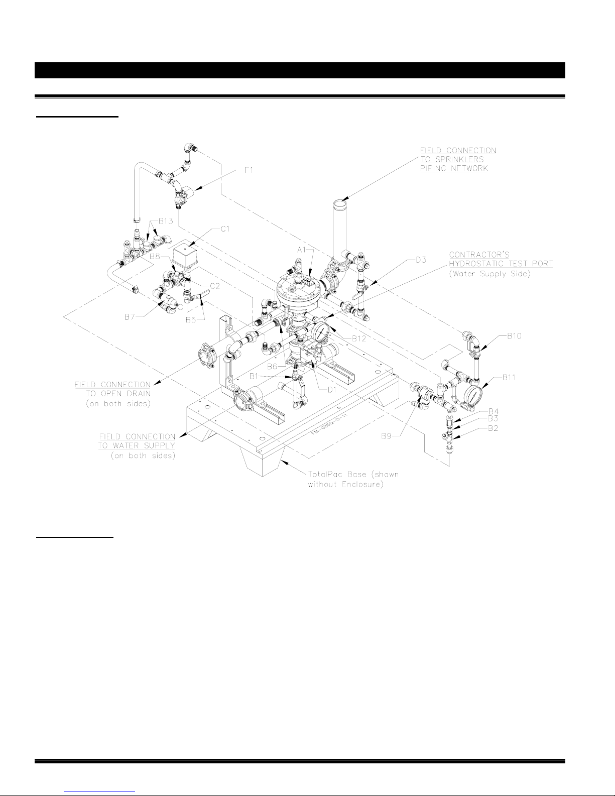
Page 12 of 12 TOTALPAC2
TOTALPAC2 Integrated Fire Protection Systems
Mechanical Section - Deluge System
Trim Schematic: System w ith electric release
Trim Components:
A. Valve:
A1 Deluge valve
B. Deluge Valve Trim:
B1 Priming valve
B2 Strainer
B3 1/16" Restricted orifice
B4 Spring loaded check valve
B5 Alarm test valve
B6 Flow test valve
B7 Drip check valve
B8 Drain check valve
B9 Pressure operated relief valve (PORV)
B10 Emergency release valve
B11 Priming pressure water gauge & valve
B12 Water supply pressure gauge & valve
B13 Clapper check valve
FM-086G-0-24D
C. Water Flo w Alarm Equipment:
C1 Alarm pressure switch
C2 Connection to water motor gong (strainer supplied
by contractor)
D. Valve:
D1 Water supply control valve
D3 Main drain valve
E. Supervisory Air Supply:
(Not Applicable)
F. Release System:
F1 N.C. solenoid valve – 24 Vdc
Page 23
TOTALPAC2 Page 1 of 2
TOTALPAC2 Integrated Fire Protection System
Trim Options
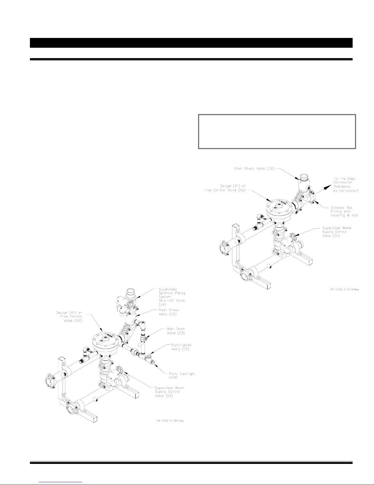
1. Shut-Off Valve & Sight Glass:
The Shut-off Valve & Sight Glass Option is intended to be
used for applications where testing of the system operation
without filling the sprinkler piping network is desirable and
where it is critical that all functions of the preaction system be
tested under actual discharge conditions. Examples of suc h
applications are freezers, ovens, museums, data processing
and other hazards where the possibility of water leaking from
the piping system is to be avoided at all costs.
Operation of the shut-off valve: Inspection of the system
can be implemented without filling the sprinkler piping system
with water.
.1 CLOSE the Supervised sprinkler piping system Shut-Off
Valve (D4); the valve is supervised on the same circuit
as the system Water Supply Control Valve (D1).
.2 OPEN the system Main Drain Valve (D3).
.3 Simulate the operation of the system to open the Deluge
(A1) or Flow Control Valve (A2) (See Annual test under
the INSPECTION AND MAINTENANCE section.) Using
a flashlight in one of the sight glasses, verify that water
flows through the Sight Glass Assembly (D5).
.4 Once tests are completed, make sure the system Main
Drain Valve (D3) is completely CLOSED. Reset the
system as per PLACING THE SYSTEM BACK IN
SERVICE.
.5 FULLY OPEN the system Shut-Off Valve (D4). Reset
the system's Release Control Panel.
Figure 1 - Test Valve for Preaction Systems
2. Fire Department Connection:
The Fire Department Connection Option consists of a
grooved Tee fitting installed in lieu of the 90 degree elbow at
the outlet of the Deluge / Flow Control Valve (A1 or A2). An
access hole of the proper diameter is factory pre- drilled on
the side of the TotalPac enclosure for connection of the
piping going to the Fire Department Connection.
Note: The Fire Department Connection hardware itself
(drain, Siamese, etc.) is NOT provided with this option and
shall be provided by the installing contractor. Refer to
NFPA-13 Standard for additional information about the
equipment layout and installation.
Figure 2 – Fire Department Connection for Preaction
Systems:
FM-086G-0-46C
Page 24
Page 2 of 2 TOTALPAC2
TOTALPAC2 Integrated Fire Protection System
Trim Options
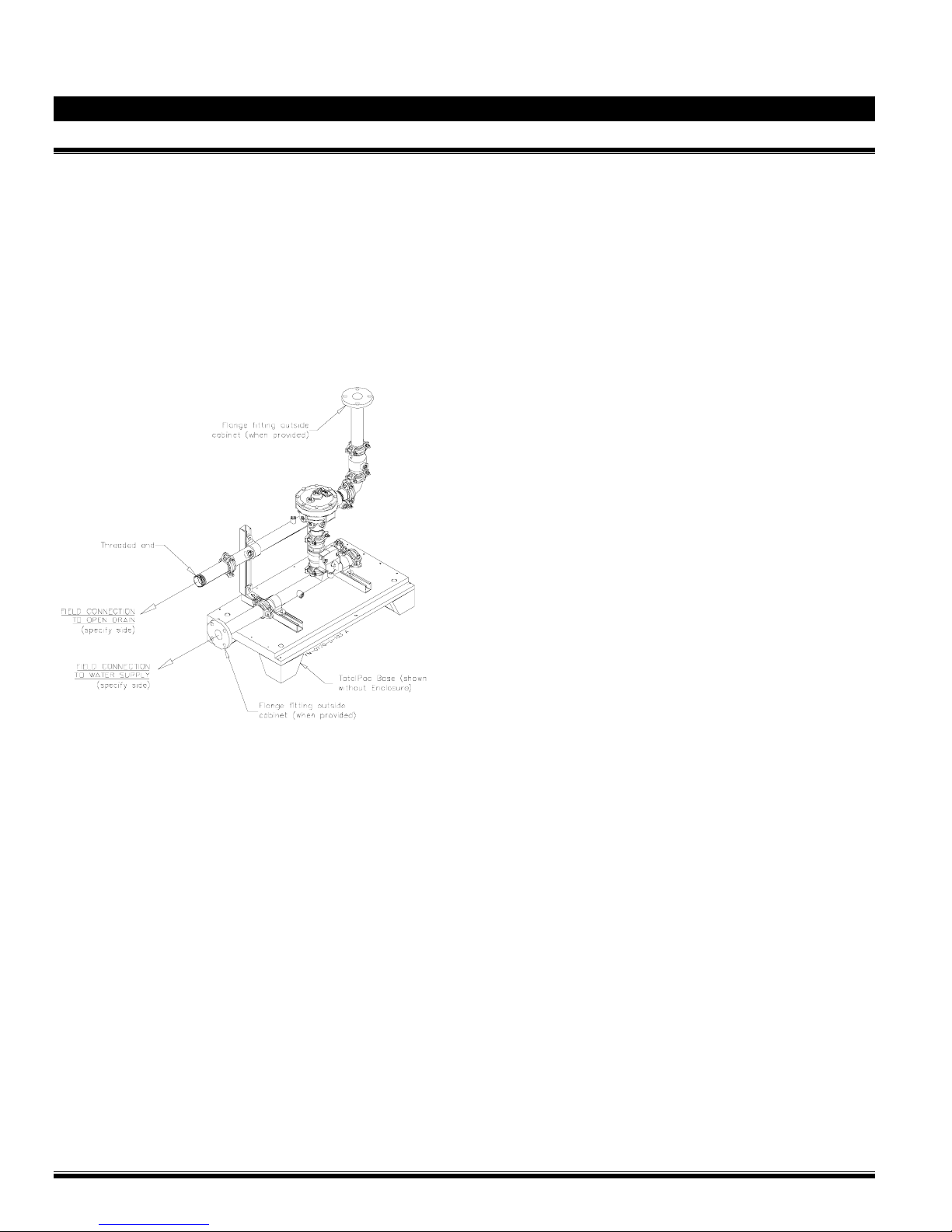
3. Semi and Full-flanged Option:
When required by the user, TotalPac2 units can be provided
in either a semi-flanged of full flanged configuration.
The semi flanged option provides flanged fittings onl y on the
water inlet pipe (side needs to be specified at the time of
order) and on the system riser outlet. The drain manifold is
then provided with a threaded end that also needs to have
it's side specified (left or right). The rest of the fittings are the
same as usual with the main components being provided in
the standard flanged -grooved configuration.
Figure 3 – Semi-flanged unit typical detail:
The full flanged option is the same as above but goes a step
further with the main components being also provided with a
flanged-flanged configuration.
When provided, the face of the flanges will always be
situated 6 inches from the outside face of the mounting base
or cabinet surface. On skid units, the surface of the flange
on the outlet riser will always be 6 inches above the
dimension shown on the dimensional data of the system
ordered.
FM-086G-0-46C
Page 25
T
OTALPAC
2
T
OTALPAC
2 Integrated Fire Protection System
Air Supply
1- Cabinet Air Supplies
Preaction, dry valve and other sprinkler systems using air
pressure for supervisory or releasing purposes are provided
with either internal or external supervised air supplies.
Four (4) styles of air supplies are available for the
T
OTALPAC
These air supplies are all factory assembled, mounted in the
cabinet and pressure tested. They are all located in the top
part of the cabinet, hung on mounting rails above the valve
trim. Here is the description of those options:
Air Supply Style "A": (Refer to Figure 1) Used only for
the sprinkler piping network of electrically operated preaction
systems and with dry pipe systems. Air supply style "A"
includes the air compressor mounted inside the T
cabinet with its supervisory trim and options. Compressors
are of the oiless piston type without reservoir and are factory
piped to the sprinkler piping system riser, all within the
T
OTALPAC
1/6HP 1/2HP
1/3HP 1HP.
All the above air compressors have open, single phase
motors with internal thermal protection and can be ordered in
two supply voltages settings:
120Vac-60Hz or 220Vac-50Hz.
The 120Vac-60Hz is the normal voltage used in Canada and
the United-States while the 220Vac-50Hz is primarily used in
Europe, Middle-East and other countries with 220 volts, 50
cycles current.
Air Supply Style "B": (Refer to Figure 2) Used only for
the sprinkler piping network of Preaction or dry pipe systems,
when an external air supply is provided by others (either
compressor, plant air or dry nitrogen cylinders) and piped to
the air inlet port of the unit. Air supply style "B" provides an
Air Pressure Maintenance Device (APMD) trim, factory
mounted in the T
Note: For the releasing system piping of pneumatically
2 units depending on needs or configurations.
OTALPAC
2 cabinet. They are available in four (4) sizes;
OTALPAC
actuated systems, use air supply type "C" or "D"
below (with an external air compressor).
2 cabinet.
Page 1 of 14
Ambient temperature at the special external air supply unit
location should not exceed 104oF (40oC). Refer to NFPA
and Factory Mutual Codes & Standards for details on
refrigerated spaces applications. Air supply style "D" can
also be used when the contractor prefers to provide his own
air supply & regulation trim, mounted outside the T
cabinet.
Note: When air supplies style "B", "C" or "D" are
selected, the air supply should be provided and
installed by the sprinkler contractor OUTSIDE of
the T
OTALPAC
the unit.
2
1.1 Air supply design and selection:
The air supply compressor should be sized to automatically
establish the total required air pressure in 30 minutes.
External air supply should be provided with an Air
Maintenance Device (air supply style "B") to regulate and
restrict the flow of supervisory air into the sprinkler system
piping.
Note: External air supply MUST always be restricted to
insure that the automatic air supply cannot
replace air as fast as it escapes when a sprinkler
operates.
WARNING ! Pressures other than the factory pressure
settings may affect the operation of the system.
Air compressor selection Table:
H.P
1/6 1.33 110 90
1/3 2.61 215 170
1/2 4.06 335 270
1 7.40 610 400
CFM @
40 psi
2 Cabinet It is NOT provided with
120Vac System
capacity (gallon)
to Pump to 40
psi in 30 Minutes
220Vac System
capacity (gallon)
to Pump to 40
psi in 30 Minutes
OTALPAC
2
Air Supply Style "C": (Refer to Figure 3) Used only for
the pneumatic release piping network of pneumatically
operated Preaction or deluge systems. An external air
supply has to be provided by others (compressor, plant air or
dry nitrogen cylinders) and piped to the air inlet port of the
unit. Air supply style "C" provides an Air Pressure
Maintenance Device (APMD) trim, factory mounted in the
T
OTALPAC
Air Supply Style "D": (Refer to Figure 4) Mainly used
with Preaction systems protecting refrigerated spaces and
freezers, where a special dry external air supply unit is piped
directly to the system riser inside the freezer itself, as shown
in NFPA-13. Air supply Style "D" provides only an air
supervisory and shut-off trim.
2 cabinet.
Note: Selection of the proper air compressor size is the
responsibility of the installing contractor.
FM-086G-0-43E
Page 26
Page 2 of 14
T
OTALPAC
2 Integrated Fire Protection System
T
OTALPAC
2
Air Supply
1.2 Connecting the Air Compressor to AC power
The motor must be protected against short circuit, overload
and excessive temperature rise. Fuses, motor protective
switches and thermal protective switches provide the
necessary protection in these circumstances.
Fuses only serve as a short circuit protection of the motor
(wiring fault), not as protection against overload. Those are
provided and wired by the electrical contractor. An isolation
switch (for location detail, refer to Figure 2 in CONTROLS
Section) is also provided in the T
OTALPAC
2 Cabinet and is
factory wired, allowing powering off the air compressor while
some maintenance work on the unit is done, without
disturbing the rest of the system.
Connect non-energized AC power to the air compressor.
Refer to figure below and FIELD WIRING DIAGRAM.
INPUT POWER SOURCE
TBB
1
2
3
4
Wiring size: Minimum 14 AWG with 600V Insulation.
Wiring of 120/220Vac Air Compressor
Branch circuit for air compressor shall not be the same
!
as the control panel power source
120Vac, 60Hz 220Vac, 50 Hz
L1
NEUTRAL
GROUND
AIR COMPRESSOR
1 HP Maximum
Power Source
1.3.2 To close air supply:
Turn off the compressor isolating switch (E15).
1.3.3 To adjust system air pressure (Furnas switch):
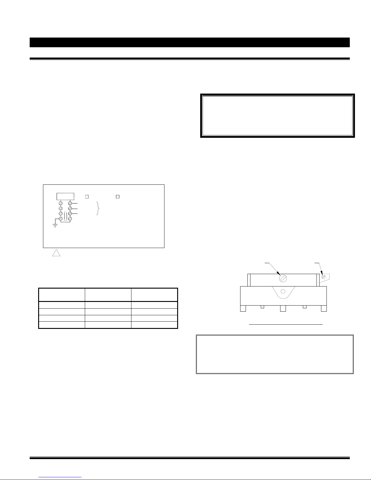
WARNING ! The cut-out/cut-in differential switch
adjustment screw (small screw to the right) is factory set.
DO NOT CHANGE ITS SETTING. Any unauthorised
modification of this setscrew adjustment will void the
system warranty and may also prevent the system from
operating normally.
The air compressor cut-off pressure switch (E2) (shown
below with its metal cover removed) has its air compressor
cut-out adjustment switch (middle screw) factory set. This
switch should not need any adjustment but if necessary,
follow the instructions below:
a) Remove the metal cover of the compressor air
pressure switch (E2).
b) To raise the cut-out pressure of the air compressor,
turn the cut-out adjustment screw (middle) half a
turn CLOCKWISE.
c) Open the system main drain valve (D3) and let the
pressure drop until the air compressor (E1) restarts.
Check pressure reading on the system pressure
gauge (E3) when the air compressor stops again.
Repeat until the desired pressure is reached. Once
all done, replace the metal cover on the switch (E2).
Turn clockwise to increase
both cut-out and cut-in
pressure adjustment.
Factory set.
DO NOT CHANGE !
COMPRESSOR Amp rating
Compressor Size
(HP)
1/6 6.8 A 2.8 A
1/3 6.5 A 3.5 A
1/2 8 A 4.8 A
1 12.4 A 7.6 A
1.3 Operation
Air Supply Style "A":
1.3.1 To Apply Air Supply:
Establish AC power for the air compressor by activating the
correspondent circuit breaker at the electrical distribution
panel. Start compressor by activating the compressor
isolating switch (E15) located in the control section of the unit
(refer to CONTROL SECTION, Fig. 2 for exact location of the
isolating switch).
If the air compressor motor fails to start or slows down under
load, shut the compressor off. Check that the supply voltage
agrees with the motor nameplate.
A Float Check Valve (E9) is provided with Air Option "A".
The Float Check Valve allows sensing of air pressure in the
system during supervisory times of the system.
FM-086G-0-43E
Amp. Rating at
120Vac – 60Hz
Amp. Rating at
220Vac – 50Hz
FM-072Q-0-109 A
Front view of the Furnass Switch
(Part # 69HA3)
Note: Do not turn the cut-out adjustment screw (middle)
all the way down in one shot. Proceed by steps.
Use the same method turning the cut-out
adjustment screw COUNTER-CLOCKWISE to
lower the air compressor cut-out pressure.
Page 27

T
OTALPAC
2
T
OTALPAC
2 Integrated Fire Protection System
Air Supply
Page 3 of 14
Air supplies style "B" or "C":
1. To Apply Air Supply:
Turn on upstream air supply. Open APMD (Air Pressure
Maintenance Device) input valve (E6) by placing handle in
line with valve body then open APMD output valve (E7) by
placing handle in line with the valve body.
In order to accelerate filling of sprinkler piping by air
pressure, bypass valve (E8) can be opened by placing
handle in line with valve body while piping is initially filled by
the air compressor,. This valve (E8) must then be closed
(handle crossways to valve body) and kept in this position
once the system is filled with air.
2. To Close Air Supply:
Close APMD output valve (E7) by placing handle crossways
to valve body then close APMD input valve (E6) by also
placing handle crossways to the valve body. Be sure bypass
valve (E8) is closed (handle crossways to valve body).
3. To Adjust System Air pressure:
Be sure APMD input valve (E6) and APMD output valve (E7)
are both open (handle in line with the valve body), and
bypass valve (E8) is closed (handle crossways to valve body)
prior to performing this operation. Loosen lock nut and turn
pressure adjustment nut clockwise to increase air pressure or
counter-clockwise to decrease pressure. Tighten lock nut.
Note: Depending on site conditions, the internal filter of
the APMD may need maintenance on a regular
basis. Refer to Viking Data Sheet # 127 for more
details.
Air supply style "D":
7. To Apply Air Supply:
Turn on upstream air supply. Open air shut-off valve (E14)
by placing handle in line with valve body.
8. To Close Air Supply:
Close bypass air shut-off valve (E14) (handle crossways to
valve body).
1.4 Maintenance and inspection:
Air supply style "A":
1. To close the Air Supply:
This procedure requires turning OFF the air compressor's
AC power by switching off the compressor isolating switch
(E15) located in the control section of the unit before
servicing. Note that the air compressor motor is equipped
with thermal protectors that reset automatically. These
thermal protectors will stop the motor in case it overheats
and can automatically start the motor when they reset.
2. To remove and clean the check valve assembly (E11):
This procedure requires turning OFF the compressor's AC
power. Follow instructions "To close Air Supply" above.
a) Carefully loosen the ¼" copper adapter, remove
copper tubing, and proceed to disassemble the
check valve assembly (E11).
b) Once disassembled, carefully clean the check valve
seat, or replace the check valve (part #
40CHSW0002) altogether if worn out components
are found.
c) Remove all brass connections, by unscrewing
gently all tubing adapters from the fittings, removing
the previously installed Teflon tape and apply new
Teflon tape on all threads. Re-install all
components and check for leaks after reconnecting
power to the air compressor.
3. To clean or replace the compressor's air inlet filter:
This procedure requires turning OFF the compressor's AC
power. Follow instructions "To close Air Supply" above.
a) The motor compressor unit should be kept dirt-free.
A dirty filter restricts air flow, and causes the pump
to run hotter and results in longer operating cycles.
b) To inspect the inlet filter, turn the black plastic cover
counter-clockwise to remove it from its case (refer to
Figure 1). Remove old felt. Clean or replace with
new one (part # B300A). DO NOT CLEAN WITH
PETROLEUM-BASED PRODUCTS.
c) Re-install filter and cap. DO NOT OPERATE
COMPRESSOR WITHOUT A FILTER.
Note: Refer to the AIR COMPRESSOR Operation &
Maintenance Technical Manual provided with the
T
OTALPAC2
Intake and exhaust filters are standard on most compressors
and will provide adequate filtration for most applications.
Check filters periodically and replace when necessary. Initial
inspection is suggested at 500 hours, then the user should
determine the frequency. Most problems can be prevented
by keeping filters and mufflers clean. Dirty filters and
mufflers decrease compressor performance and can
decrease compressor service life.
Should the compressor need rebuilding, field rebuilt kits are
available from Authorized Service Facilities. Refer to the
compressor's Owner's Manual provided with the T
unit. Maintain a clean air filter cartridge to insure best flow
and performance. The location and the quality of the air
being ingested indicate the frequency for inspection and
replacement. A dirty filter restricts air flow, causes the pump
to run hotter and results in longer operating cycles.
unit for more details.
OTALPAC
2
FM-086G-0-43E
Page 28

Page 4 of 14
4. To drain the Air Supply Accumulator:
The amount of moisture pumped into the system and how
quickly it accumulates is proportional to the amount of
humidity in the air and how long the compressor is in
operation. This unit has been designed to operate between
32 and 100oF.
At least once a year, open air option Drain Valve (E12) until
all condensate water is drained from the air receiver. Close
air option Drain Valve.
WARNING ! The relief valve and outlet pipe of the air
compressor may become very hot during normal
operation. Do not touch the valve, compressor heads or
outlet piping until the compressor has been turned off and
allowed to cool.
A safety relief valve is provided on standard compressors
and is preset at the factory. Do not exceed or adjust safety
relief pressures other than those preset at the factory.
WARNING ! Do not unscrew relief valve head entirely off
while the compressor is operating. Ejection of valve parts
could cause severe injury.
Air supplies style "B" or "C":
The Viking Model D-2 Air Pressure Maintenance Device
(APMD) (E5) is a pressure regulator that automatically
reduces the supply air pressure to a pre-set requirement
when connected to a constantly maintained air supply (plant
air, external tanked air compressor or dry nitrogen tank).
Refer to Figure 2 or 3 for details.
Features:
• Replaceable air filter
• Outlet pressure range is 5 to 75 psi ( ± 2 psi) (34,47 to
• Ball check to prevent back flow.
• Restriction 1/16" (1,59mm) to prevent rapid re-
The Viking Model D-2 APMD (E5) regulates and restricts air
flow.
• The air or nitrogen supply provided to the APMD must be
• By-pass piping is provided to allow initial pressurization
T
OTALPAC
517,11 kPa). Air pressure setting can be readjusted
after installation. See Paragraph 3.6, TO ADJUST
SYSTEM AIR PRESSURE.
pressurization of a system.
continuous, clean, dry and oil free.
of system piping more rapidly than the restricted air flow
through the APMD will allow.
2 Integrated Fire Protection System
Air Supply
The APMD (E5) should be checked for correct pressure
regulation after installation or repair by noting the air
pressure reading within the system. If adjustment is
required, refer to paragraph 1.3 of the current Section. The
filter should also be inspected and replaced or cleaned as
required.
To clean Air Pressure Maintenance Device (APMD) (E5) in
Air option B (refer to Figure 2):
Refer to Viking Data Sheet 127 for additional details.
To close the Air Supply:
Close Air Pressure Maintenance Device (APMD) output
isolation valve (E7) by placing handle crossways to the valve
body. Make sure the APMD input valve (E6) is open (handle
in line with valve body), and the bypass valve (E8) is closed
(handle crossways to valve body). Refer to Figure 2 or 3.
Important: Advise local authorities of the necessary work
T
OTALPAC
2
• If adjustment is necessary, refer to paragraph 1.3 of
the current Section
• Do not disconnect or disassemble the APMD
without closing the outlet (E7) and inlet (E6)
isolation valves. System air pressure will be trapped
between the outlet of the APMD and the
downstream control valve. Relieve pressure before
proceeding with disassembly.
• This procedure requires turning OFF the
compressor's power.
• Carefully loosen the union between the outlet of
APMD (E5) and the outlet isolation valve (E7) to
relieve pressure.
• Remove and clean Air Pressure Maintenance
Device (APMD) filter. Refer to VIKING Technical
Data Sheet 127 Model D-2 Air Pressure
Maintenance Device for more details. If admission
filter is blocked, replace with filter kit (part # 03007
A).
Air supply style "D":
• The air or nitrogen supply provided must be
continuous, clean, dry and oil free.
• Determine the appropriate pressure to be
maintained in the system. Refer to System Data
and Technical Data for the system and components
used.
over the fire protection equipment. In order to avoid
accidental water release, it is considered good practice to
completely close the main water inlet valve while doing
maintenance work.
• Determine the appropriate pressure to be maintained in
the system. Refer to Table 1 or Table 2 of the current
Section.
FM-086G-0-43E
WARNING !
be relatively hot after the air compressor has run for some
time. Take precautions when handling the components to
avoid skin burns.
Air compressor head and copper tubing may
Page 29
T
OTALPAC
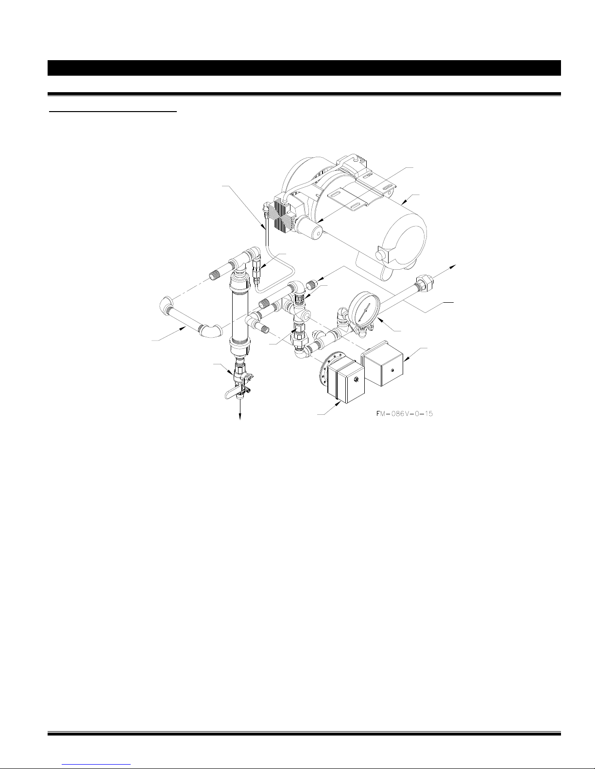
Figure 1 – Air Supply Style "A"
(Cabinet mounted air compressor)
2
T
OTALPAC
2 Integrated Fire Protection System
Air Supply
Air compressor filter
Page 5 of 14
Pipe replaced by
Dehydrator Option
(when used)
Copper tubing
E12
To drain collector
E9
E11
E2
E10
E3
E1
To sprinklers riser
Plug removed for
Optional accelerator or
Pneumatic actuator
(when used)
E4
Air Option Components:
E1 Air compressor
E2 Air compressor "Cut-off" pressure switch
E3 System air pressure gauge
E4 Air supervisory pressure switch
E9 Float check valve
E10 Soft-seat check valve
E11 Air compressor check valve
E12 Air option drain valve
E15 Compressor isolating switch (not shown)
Optional Components:
(see Air Supply Options for details)
- Viking Dehydrator
- Accelerator
FM-086G-0-43E
Page 30
Page 6 of 14
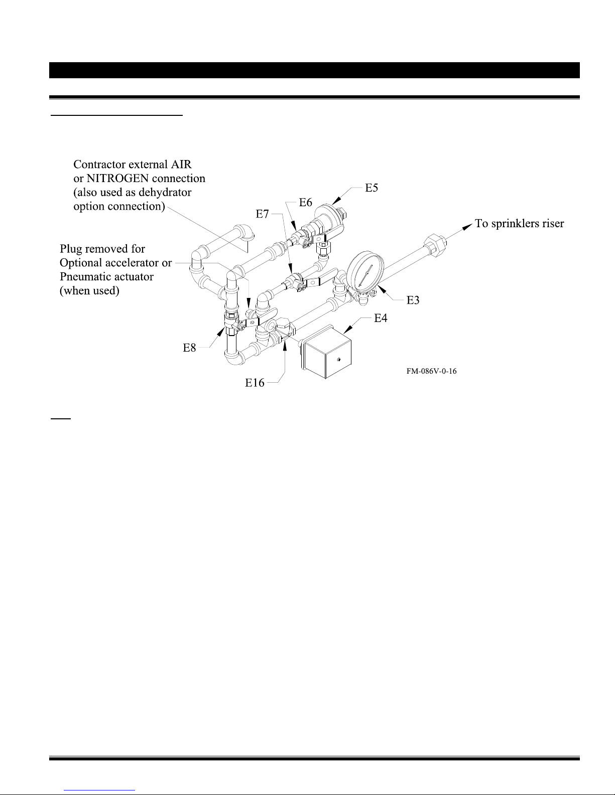
Figure 2 – Air Supply Style "B"
(APMD without air compressor)
T
OTALPAC
2 Integrated Fire Protection System
Air Supply
T
OTALPAC
2
Note: The external air supply must be restricted to insure that it cannot replace air as fast as it escapes when a releasing device or
sprinkler operates. When the system is put in service, open the input valve (E6) first.
Air Option Components:
E3 System air pressure gauge
E4 Air supervisory pressure switch
E5 Air pressure maintenance device (APMD)
E6 APMD input valve
E7 APMD output valve
E8 APMD bypass valve
E16 Swing check valve
Optional Components:
(see Air Supply Options for details)
- Viking Dehydrator
- Accelerator
FM-086G-0-43E
Page 31
T
OTALPAC
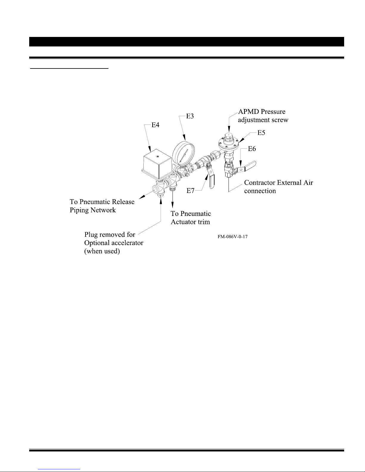
Figure 3 – Air Supply Style "C"
(APMD for Pilot Line release system only)
2
T
OTALPAC
2 Integrated Fire Protection System
Air Supply
Page 7 of 14
Air Option Components:
E3 System air pressure gauge
E4 Air supervisory pressure switch
E5 Air pressure maintenance device (APMD)
E6 APMD input valve
E7 APMD output valve
Optional Components:
(see Air Supply Options for details)
- Accelerator
FM-086G-0-43E
Page 32
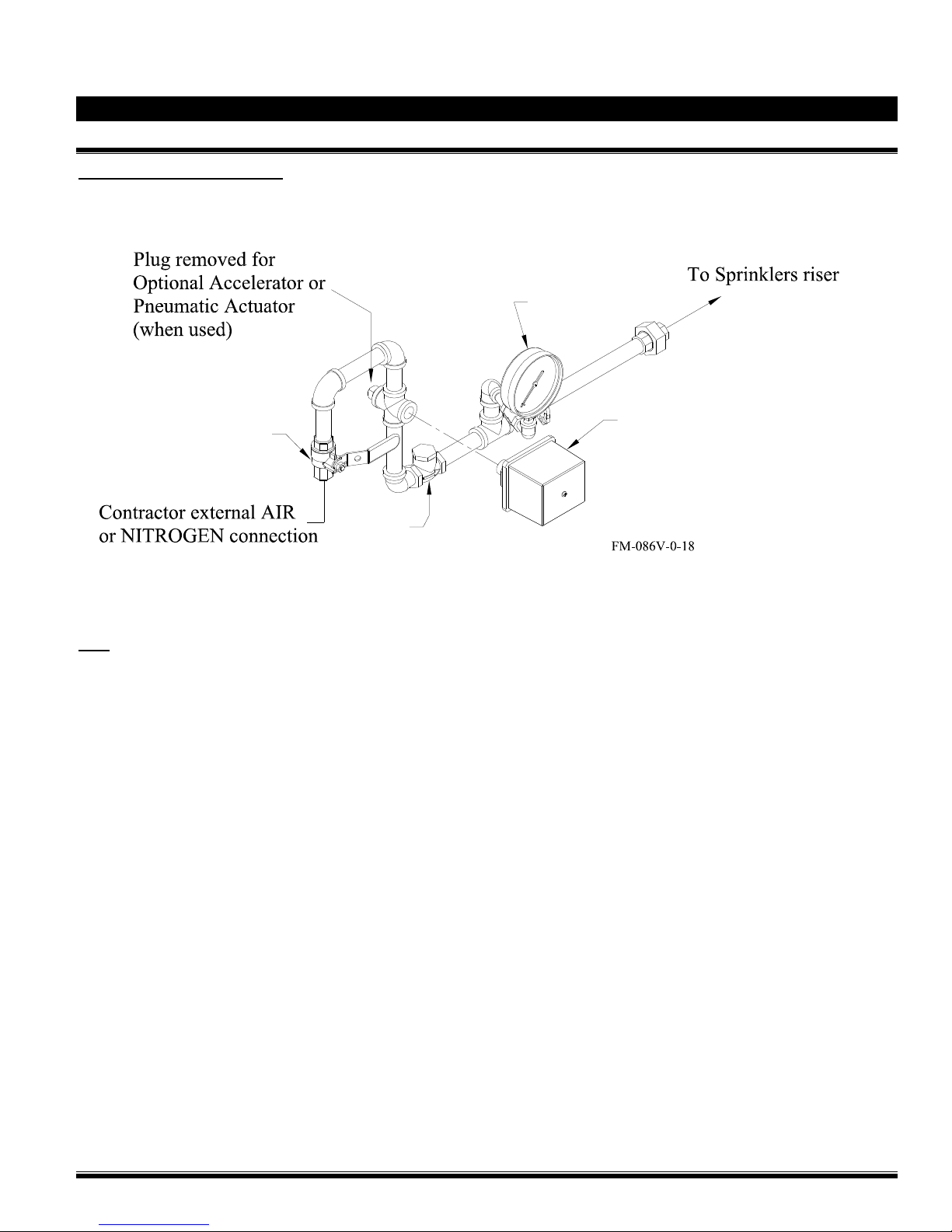
Page 8 of 14
Figure 4 – Air Supply Style "D"
T
OTALPAC
E6
2 Integrated Fire Protection System
Air Supply
(Air supply connection only for external air supply)
E3
E4 (replaced by a plug on
SUREFIRE trim)
E16
T
OTALPAC
2
Note: The external air supply must be restricted to insure that it cannot replace air as fast as it escapes when a releasing device or
sprinkler operates.
Air Option Components:
E3 System air pressure gauge
E4 Air supervisory pressure switch
E6 Air shut-off valve
E16 Swing check valve
Optional Components:
(see Air Supply Options for details)
- Viking Dehydrator
- Accelerator
FM-086G-0-43E
Page 33

T
OTALPAC
Table 1: Water Pressure up to 175 Psi
System Type
Non-Interlocked
Pneumatic Release
Non-Interlocked
Electric Release
Single-Interlocked
Pneumatic Release
Single-Interlocked
Electric Release
Double-Interlocked
Pneumatic/Pneumatic
Electric/PneuLectric
Electric/Pneumatic
Single-Interlocked
Firecycle III
Double-Interlocked
Firecycle III
Single-Interlocked
SUREFIRE
Double-Interlocked
SUREFIRE
Release (pilot) Line C
Dry Pipe System
2
T
OTALPAC
Air Supply
Style
B or D
B or D
B or D
B or D
B or D
B or D
B or D
B or D
B or D
B or D
B or D
B or D
2 Integrated Fire Protection System
Air Supply
Air
Regulator
A n/a
30 Psi
(207 kPa)
A n/a
30 Psi
(207 kPa)
A n/a
30 Psi
(207 kPa)
A n/a
20 Psi
(138 kPa)
A n/a
30 Psi
(207 kPa)
A n/a
20 Psi
(138 kPa)
A n/a
30 Psi
(207 kPa)
A n/a
30 Psi
(207 kPa)
A n/a
30 Psi
(207 kPa)
A n/a
30 Psi
(207 kPa)
A n/a
30 Psi
(207 kPa)
30 Psi
(207 kPa)
A n/a
30 Psi
(207 kPa)
Compressor
Start
30 Psi
(207 kPa)
n/a
30 Psi
(207 kPa)
n/a
30 Psi
(207 kPa)
n/a
15 Psi
(104 kPa)
n/a
30 Psi
(207 kPa)
n/a
15 Psi
(104 kPa)
n/a
30 Psi
(207 kPa)
n/a
30 Psi
(207 kPa)
n/a
30 Psi
(207 kPa)
n/a
30 Psi
(207 kPa)
n/a n/a
30 Psi
(207 kPa)
n/a n/a
n/a
30 Psi
(207 kPa)
n/a n/a
Compressor
Stop
35 Psi
(242 kPa)
n/a
35 Psi
(242 kPa)
n/a
35 Psi
(242 kPa)
n/a
20 Psi
(138 kPa)
n/a
35 Psi
(242 kPa)
n/a
20 Psi
(138 kPa)
n/a
35 Psi
(242 kPa)
n/a
35 Psi
(242 kPa)
n/a
35 Psi
(242 kPa)
n/a
35 Psi
(242 kPa)
35 Psi
(242 kPa)
n/a
35 Psi
(242 kPa)
Low Air
Supervisory
25 Psi
(173 kPa)
25 Psi
(173 kPa)
25 Psi
(173 kPa)
25 Psi
(173 kPa)
25 Psi
(173 kPa)
25 Psi
(173 kPa)
12 Psi
(83 kPa)
12 Psi
(83 kPa)
25 Psi
(173 kPa)
25 Psi
(173 kPa)
12 Psi
(83 kPa)
12 Psi
(83 kPa)
25 Psi
(173 kPa)
25 Psi
(173 kPa)
25 Psi
(173 kPa)
25 Psi
(173 kPa)
25 Psi
(173 kPa)
25 Psi
(173 kPa)
25 Psi
(173 kPa)
25 Psi
(173 kPa)
25 Psi
(173 kPa)
25 Psi
(173 kPa)
25 Psi
(173 kPa)
25 Psi
(173 kPa)
25 Psi
(173 kPa)
Low Air
Alarm
n/a
n/a
23 Psi
(NYC)
23 Psi
(NYC)
n/a
n/a
10 Psi
(NYC)
10 Psi
(NYC)
n/a
n/a
10 Psi
(69 kPa) Double-Interlocked
10 Psi
(69 kPa)
23 Psi
(NYC) Double-Interlocked
23 Psi
(NYC)
23 Psi
(159 kPa)
23 Psi
(159 kPa)
23 Psi
(159 kPa)
23 Psi
(159 kPa)
23 Psi
(159 kPa)
23 Psi
(159 kPa)
23 Psi
(159 kPa)
23 Psi
(159 kPa)
n/a
n/a
n/a
Page 9 of 14
FM-086G-0-43E
Page 34

Page 10 of 14
Table 2: Water Pressure from 175 Psi to 250 Psi
T
OTALPAC
System Type
Non-Interlocked
Pneumatic Release
Non-Interlocked
Electric Release
Single-Interlocked
Pneumatic Release
Single-Interlocked
Electric Release
Double-Interlocked
Pneumatic/Pneumatic
Double-Interlocked
Electric/PneuLectric
Electric/Pneumatic
Single-Interlocked
Firecycle III
Double-Interlocked
Firecycle III
Single-Interlocked
SUREFIRE
Double-Interlocked
SUREFIRE
Release (pilot) Line C
Dry Pipe System
Air Supply
Style
A n/a
B or D
A n/a
B or D
A n/a
B or D
A n/a
B or D
A n/a
B or D
A n/a
B or D
A n/a
B or D
A n/a
B or D
A n/a
B or D
A n/a
B or D
A n/a
B or D
A n/a
B or D
2 Integrated Fire Protection System
Air
Regulator
50 Psi
(345 kPa)
50 Psi
(345 kPa)
50 Psi
(345 kPa)
20 Psi
(138 kPa)
50 Psi
(345 kPa)
20 Psi
(138 kPa)
50 Psi
(345 kPa)
50 Psi
(345 kPa)
50 Psi
(345 kPa)
50 Psi
(345 kPa)
50 Psi
(345 kPa)
50 Psi
(345 kPa)
50 Psi
(345 kPa)
Air Supply
Compressor
Start
50 Psi
(345 kPa)
n/a
50 Psi
(345 kPa)
n/a
50 Psi
(345 kPa)
n/a
15 Psi
(104 kPa)
n/a
50 Psi
(345 kPa)
n/a
15 Psi
(104 kPa)
n/a
50 Psi
(345 kPa)
n/a
50 Psi
(345 kPa)
n/a
50 Psi
(345 kPa)
n/a
50 Psi
(345 kPa)
n/a n/a
50 Psi
(345 kPa)
n/a n/a
n/a
50 Psi
(345 kPa)
n/a n/a
Compressor
Stop
55 Psi
(380 kPa)
n/a
55 Psi
(380 kPa)
n/a
55 Psi
(380 kPa)
n/a
20 Psi
(138 kPa)
n/a
55 Psi
(380 kPa)
n/a
20 Psi
(138 kPa)
n/a
55 Psi
(380 kPa)
n/a
55 Psi
(380 kPa)
n/a
55 Psi
(380 kPa)
n/a
55 Psi
(380 kPa)
55 Psi
(380 kPa)
n/a
55 Psi
(380 kPa)
Low Air
Supervisory
45 Psi
(311 kPa)
45 Psi
(311 kPa)
45 Psi
(311 kPa)
45 Psi
(311 kPa)
45 Psi
(311 kPa)
45 Psi
(311 kPa)
12 Psi
(83 kPa)
12 Psi
(83 kPa)
45 Psi
(311 kPa)
45 Psi
(311 kPa)
12 Psi
(83 kPa)
12 Psi
(83 kPa)
45 Psi
(311 kPa)
45 Psi
(311 kPa)
45 Psi
(311 kPa)
45 Psi
(311 kPa)
45 Psi
(311 kPa)
45 Psi
(311 kPa)
45 Psi
(311 kPa)
45 Psi
(311 kPa)
45 Psi
(311 kPa)
45 Psi
(311 kPa)
45 Psi
(311 kPa)
45 Psi
(311 kPa)
45 Psi
(311 kPa)
T
OTALPAC
Low Air
Alarm
n/a
n/a
43 Psi
(NYC)
43 Psi
(NYC)
n/a
n/a
10 Psi
(NYC)
10 Psi
(NYC)
n/a
n/a
10 Psi
(69 kPa)
10 Psi
(69 kPa)
43 Psi
(NYC) Double-Interlocked
43 Psi
(NYC)
43 Psi
(297 kPa)
43 Psi
(297 kPa)
43 Psi
(297 kPa)
43 Psi
(297 kPa)
43 Psi
(297 kPa)
43 Psi
(297 kPa)
43 Psi
(297 kPa)
43 Psi
(297 kPa)
n/a
n/a
n/a
2
FM-086G-0-43E
Page 35

T
OTALPAC
2
T
OTALPAC
2 Integrated Fire Protection System
Air Supply
Page 11 of 14
2- Skid Air Supply Option
When TotalPac2 units are provided in skid form, the air
supply is provided by the installing contractor. Preaction, dry
valve and other sprinkler systems skids using air pressure for
supervisory or releasing purposes are all provided without
the external supervised air supplies.
The system trim includes only a connection for the air supply
including a ball valve, a pressure switch and a pressure
gauge, adapted to the particular layout ordered. When an air
pressure maintenance device is required, it shall also be
provided and installed by the contractor along with his air
supply.
The skid air supply trim is factory assembled, mounted in the
system trim and pressure tested.
អអអអ Skid Air Supply for sprinklers: (Refer to Figure 1)
Provides only an air supervisory and shut-off trim. Used
with the contractor provided air supply & regulation trim,
mounted separate from the T
អអអអ Skid Air Supply for pilot line: (Refer to Figure 2) Very
similar to the air supply for sprinklers, it provides only an
air supervisory and shut-off trim. Used with the contractor
provided air supply & regulation trim, mounted separate
from the T
2.1 Air supply design and selection:
The air supply compressor should be sized to
automatically establish the total required air pressure in 30
minutes. External air supply should be provided with an air
pressure maintenance device to regulate and restrict the
flow of supervisory air into the sprinkler system piping.
Note: External air supply MUST always be restricted to
insure that the automatic air supply cannot replace air as
fast as it escapes when a sprinkler operates.
WARNING! Pressures other than the factory pressure
settings may affect the operation of the system.
OTALPAC
2 trim skid.
OTALPAC
2 trim skid.
2.2 Operation
.1 To Apply Air Supply:
Turn on upstream air supply. Open Air shut-off
valve (E14) by placing handle in line with valve body.
.2 To Close Air Supply:
Close Air shut-off valve (E14) (handle crossways to valve
body).
3. Maintenance and inspection:
- The air or nitrogen supply provided must be continuous,
clean, dry and oil free.
- Determine the appropriate pressure to be maintained in
the system. Refer to Table 1 or 2
Important: Advise local authorities of the necessary work
over the fire protection equipment. In order to avoid
accidental water release, it is considered good practice to
completely close the main water inlet valve while doing the
maintenance work.
FM-086G-0-43E
Page 36
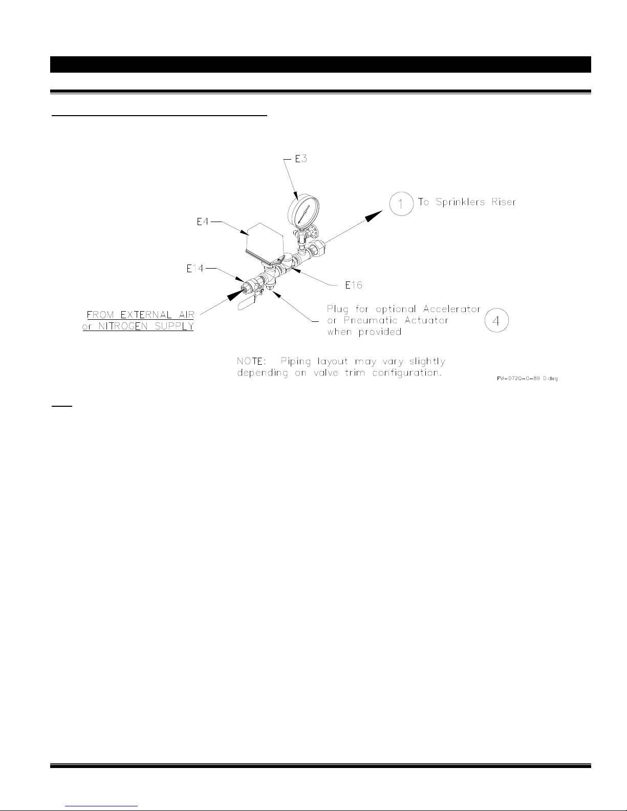
Page 12 of 14
Figure 1 – Skid Air Supply for Sprinklers Network
(Air supply connection only for external air supply )
T
OTALPAC
2 Integrated Fire Protection System
Air Supply
T
OTALPAC
2
Note: The external air supply must be restricted to insure that it cannot replace air as fast as it escapes when a releasing device or
sprinkler operates.
Air Option Components:
E3 System air pressure gauge
E4 Air supervisory pressure switch
E14 Air shut-off valve
E16 Swing check valve
Optional Components:
(see Air Supply Options for details)
- Accelerator
FM-086G-0-43E
Page 37
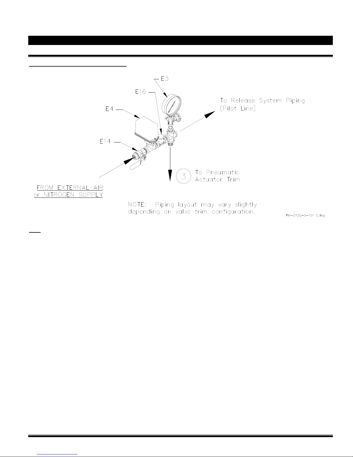
T
OTALPAC
Figure 2 – Skid Air Supply for Pilot Line
(Air supply connection only for external air supply )
2
T
OTALPAC
2 Integrated Fire Protection System
Air Supply
Page 13 of 14
Note: The external air supply must be restricted to insure that it cannot replace air as fast as it escapes when a releasing device or
sprinkler operates.
Air Option Components:
E3 System air pressure gauge
E4 Air supervisory pressure switch
E14 Air shut-off valve
E16 Swing check valve
Optional Components:
(see Air Supply Options for details)
- Accelerator
FM-086G-0-43E
Page 38

Page 14 of 14
T
OTALPAC
2 Integrated Fire Protection System
Air Supply
T
OTALPAC
2
This page was intentionally left blank
FM-086G-0-43E
Page 39
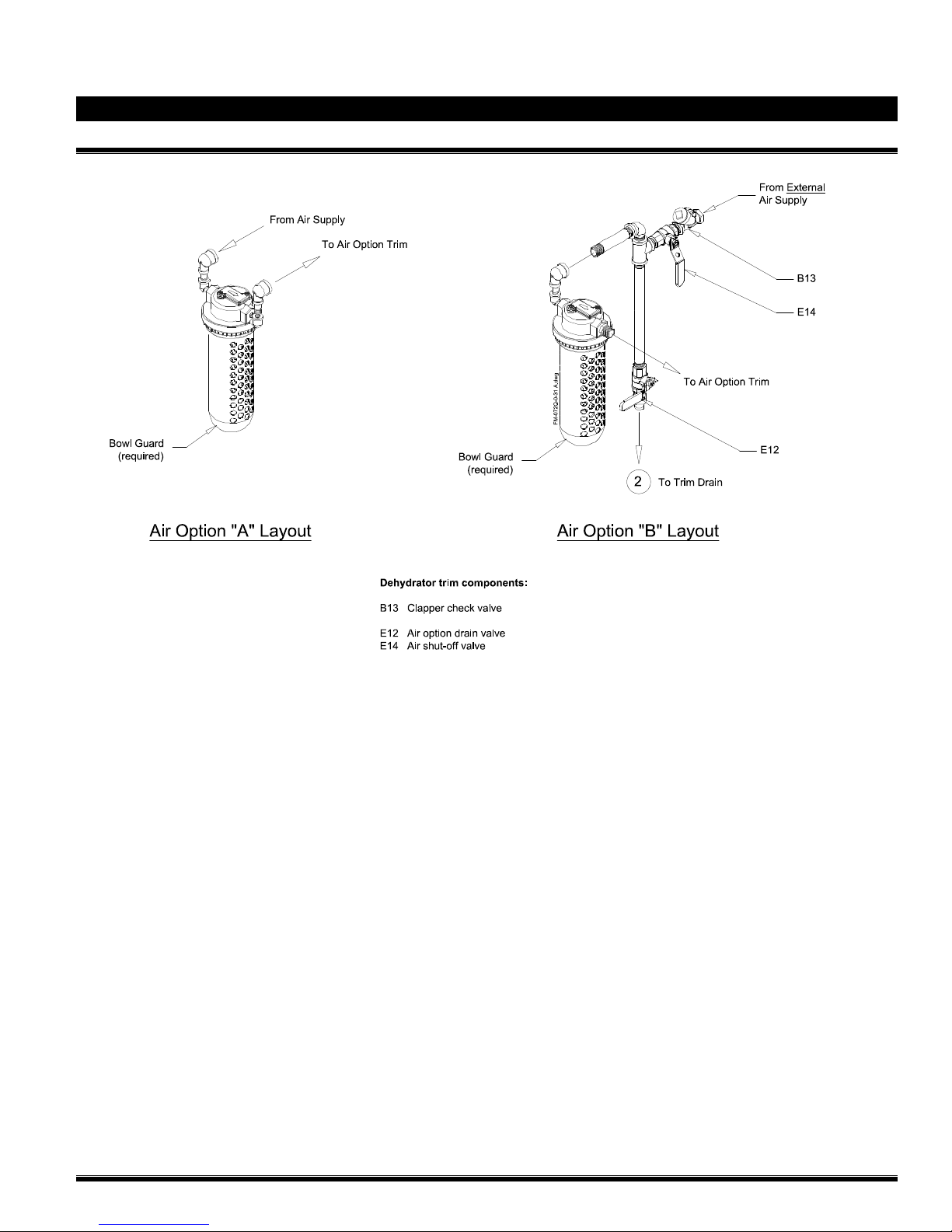
T
OTALPAC
2
T
OTALPAC
2 Integrated Fire Protection System
Air Supply Dehydrator Option
Page 1 of 2
Viking Dehydrator:
The Viking Dehydrator is a manually regenerated desiccanttype air dryer. The desiccant acts as a moisture indicator by
changing color, and is visible through the required bowl
guard and transparent plastic bowl.
Technical Information:
1. The desiccant is silica gel having a –45oF. (-43oC) dew
point at a maximum of 90oF (32oC) temperature with a
regeneration temperature of 350oF (177oC). When the
silica gel color changes from dark blue to light pink or
clear, it has become saturated with moisture and must
be changed.
2. The unit has a drying capacity of 4400 standard cubic
feet (124,6m3) of air to –45oF (-43oC) atmospheric dew
point at rated specifications before the desiccant
becomes saturated.
3. The maximum air flow rating is 10 standard cubic feet
per minute (0,283m3/minute) at 100 psi (689.5 kPa) per
unit.
4. All ratings are based on 70oF (21oC) saturated inlet air
temperatures at 100 psi (689.5 kPa).
5. The polycarbonate plastic bowl holds 1.64 pounds (0,74
kg) of desiccant and is rated for a maximum temperature
and pressure at 125oF (52oC) and 150 psi (1034 kPa).
6. The silica gel desiccant is provided in a sealed 1.75
pound (0,794 kg) bag and is shipped in a box inside the
unit cabinet.
7. The unit is to be used on compressed air service only.
Operation of Dehydrator:
The plastic bowl of dehydrator is filled with silica gel. As the
relative humidity increases, the silica gel absorbs the
moisture and begin to change color from dark blue to light
pink, indicating the desiccant must be replaced.
To Make Dehydrator Functional:
Drain valve (E12) shall be closed.
To Drain Dehydrator input line:
CLOSE air shut-off valve (E14). OPEN drain valve (E12) to
drain input line then close it. OPEN air shut-off valve (E14).
To replace Dehydrator cartridge:
Once it has been drained, CLOSE the Dehydrator air shut-off
valve (E14).
Unscrew both the bowl guard and the transparent bowl.
Replace desiccant with a fresh charge.
Follow instructions described on Viking data sheet no. 276
(Form No. F_042089) provided with the silicagel recharge.
FM-086G-0-44C
Page 40

Page 2 of 2
T
OTALPAC
2 Integrated Fire Protection System
Air Supply Dehydrator Option
This page was intentionally left blank
T
OTALPAC
2
FM-086G-0-44C
Page 41
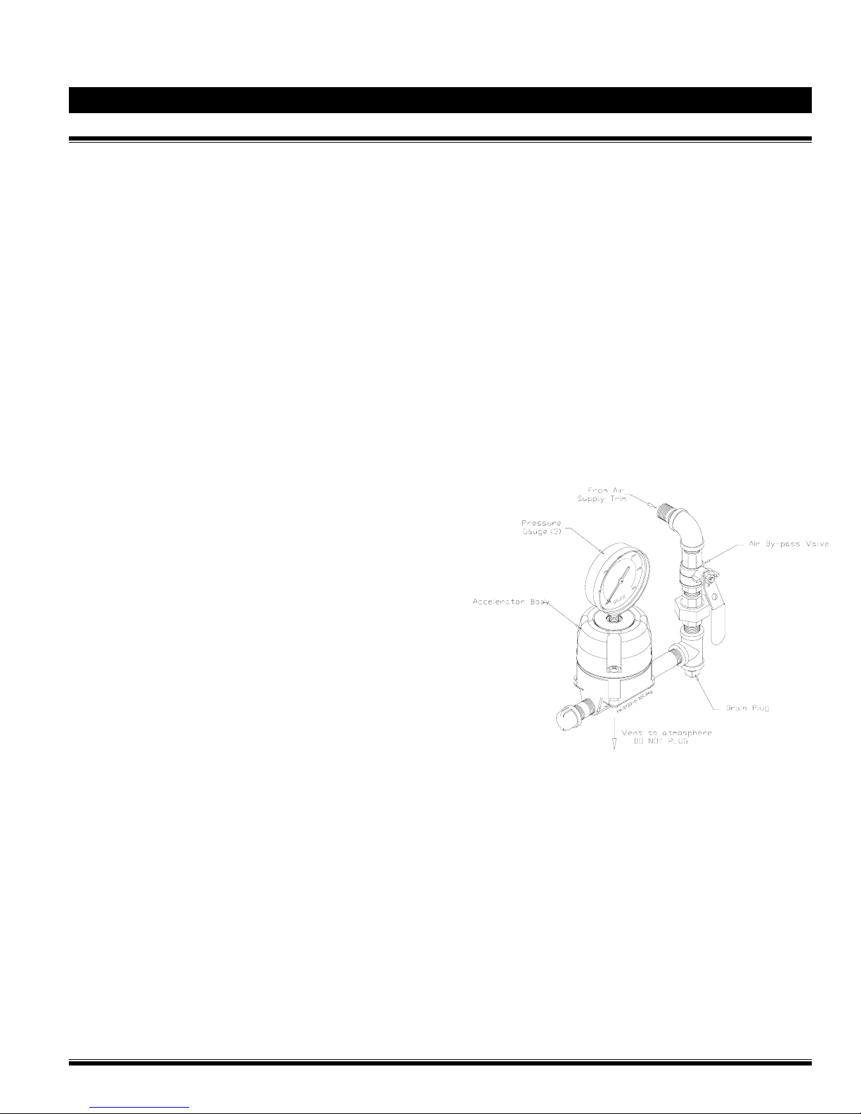
TOTALPAC2 Page 1 of 2
TOTALPAC2 Integrated Fire Protection System
Accelerator Option
Viking Accelerator:
The Viking Model E-1 Accelerator is a quick-opening
device. When installed with the required external Anti-flood
Device (on dry pipe systems only), it is used to increas e the
operational speed of a differential type valve. An
accelerator (quick-opening device) is recommended on a ll
differential dry pipe valves and is required on dry pipe
systems of certain capacities. Refer to NFPA Standards
and Authorities Having Jurisdiction. The Viking Mode l E-1
Accelerator may also be used without the Anti-flood device
to speed the action of a pneumatic release system on a
deluge, flow control or preaction system.
Features:
.A Automatically resets.
.B External anti-flood Assembly.
.C UL Listed for use on systems of maximum capacity
allowed.
.D Factory tested.
Operation:
The Viking Model E-1 Accelerator operates on the principle
of unbalanced pressures. As the accelerator is
pressurized, air enters the inlet chamber, goes through the
screen filter into the middle chamber and through an orifice
into the lower chamber. From the middle chamber, air
slowly enters the upper chamber through a filtered orifice
restriction in the cover diaphragm.
In the SET position, the system air pressure is the same in
all chambers. When a sprinkler or release device operates,
the pressure in the middle and lower chambers is reduced
at the same rate as the system pressure. The orifice
restriction in the cover diaphragm restricts the air flow from
the upper chamber, temporarily causing higher pressur e in
the upper chamber.
The pressure differential forces the cover diaphragm down,
pushing the actuator rod down. This action vents the
pressure from the lower chamber to the outlet vent,
allowing residual pressure in the inlet chamber to force the
clapper diaphragm open. After the clapper diaphragm
opens, any pressure remaining in the inlet chamber and
associated piping is vented to atmosphere.
On a pneumatic release system, when the accelerator
operates, the outlet pressure is vented to atmosphere,
speeding the release system operation.
To enable the Accelerator Device:
The Accelerator Device is enabled the Air Bypass Valve is
opened (handle aligned with the valve body). T he system air
pressure should be higher or equal to the pressure indicated
on the pressure gauge (3) prior to opening the Main Water Ilet
Valve (D1).
Ensure that the Air Bypass Valve is open (handle aligned wit h
the valve body) in normal supervisory mode.
To isolate the Accelerator Device:
Close the Air Bypass Valve, positi oning the handle across the
valve body. This operation can be nec essary in order to verif y
the pressure adjustments or to allow the pressure switches
adjustments.
Refer to instructions described on Viking datasheet no. 122
(Form No. 071692).
Viking Accelerator Model E-1 :
(for preaction systems & pilot lines)
FM-086G-0-45B
Page 42

Page 2 of 2 TOTALPAC2
TOTALPAC2 Integrated Fire Protection System
Accelerator Option
Resetting the Accelerator device:
Make sure the system is properly drained and reset.
Observe the air pressure gauge (3) on top of the
accelerator. The gauge must read zero before the
accelerator will automatically reset. It may be necessary to
loosen, remove and re-install the accelerator air gauge
(use the appropriate wrench) to vent trapped air pressur e
from the upper chamber, even when the gauge indicates
zero if the air supply is on while performing the reset.
Make sure system is pressurized according to
recommended settings. Do not exceed 60 Psi (414 kPa).
INSPECTION & TESTS:
After every operation, and each time water is allowed to
enter the system:
1. Inspect the interior of the accelerator for the presence
of water. Dampness or condensation may indicate
that the air supply is not being dried adequately. If
water is allowed to enter the middle or upper chamber
of the accelerator, it may contaminate the accelerator
orifices and prevent it from operating properly.
2. Remove the 1/2" NPT plug from the base of the
accelerator. If water or dampness is present, the
accelerator must be disassembled, cleaned and dried.
For more information about this procedure, refer to
Viking datasheet 122 (Form No. 071692).
3. Weekly inspection is recommended unless system is
provided with low air alarm, then monthly inspection
may be adequate.
4. Check the air pressure gauge (3) at the top of the
accelerator. Air pressure in the upper chamber of the
accelerator should be equal to the air pressure
maintained in the system on which it is installed.
Note: Standard tolerance allowance in pressure gauge
calibration may result in a slight variation when pressure
readings of any two gauges are compared.
A difference in pressure other then slight variation due to
gauge calibration may indicate gauge malfunction, plugged
accelerator orifices and/or filters, or other maintenance is
required. See Viking datasheet 122 (Form No. 071692),
paragraph. 12 ACCELERATOR MAINTENANCE.
5. Verify that all other trim valves are in their normal
operating position.
6. Check for signs of mechanical damage and/or
corrosive activity. If detected, perform maintenance
as required or, if necessary, replace device.
7. Verify that the water suppl y main c ontro l valv e is open
and secure and that the by-pass valve (1) is open.
FM-086G-0-45B
Page 43

TOTALPAC2 Page 1 of 8
TOTALPAC2 Integrated Fire Protection System
Control Section
1- Control Section with Control Panel
1.1 Product Description
The Control Panel Section of the Self-Contained
T
OTALPAC2 unit is an add-on cabinet that is installed on
the top of the trim enclosure at the factory. This cabinet is
fabricated of Gauge 14 steel, painted fire red with baked
powder paint making it rustproof, the same finish as the
Trim Enclosure.
The Control Panel Section is provided with a locked
stainless steel door on the front giving access to the basic
controls of the Control Panel. Once opened, the cabinet
door gives access to the panel's Terminal Strip (refer to
FIELD WIRING DIAGRAM for additional details), the
control panel main board, emergency batteries and other
related equipment. Refer to Figures 1 and 2 for additional
details.
1.2 Self-contained T
Control Panel)
The model VFR-400 is a listed and approved,
microprocessor based fire control/releasing panel. It is
primarily designed for use as a releasing panel for preaction, Surefire
extinguishing systems. The panel is available for us e with
either 120VAC-60Hz or 220VAC-50Hz power supplies.
The battery compartment can hold two 12 volt batteries
which are charged by an internal battery charger.
Batteries are available to provide up to 90 hours of
backup power during AC power failure.
The VFR-400 panel can be used with a wide range of
compatible initiating devices such as pull stations, heat
detectors (including linear heat detectors), photo-electric
and ionization smoke detectors.
Pre-configured programs allow field programming for one
of twelve possible input/output combinations that are
available and listed for use with the T
In fire conditions when an initiating device circuit (or
predetermined combination of circuits) is energized, the
panel activates the release and signaling circuits
according to the 'Program' setting.
On the panel's display board, the appropriate Alarm,
Trouble and Supervisory LED's will flash until the event
has been acknowledged. A message will be displayed on
the LCD as well.
WARNING ! For more information and technical data,
please see the VIKING VFR-400 INSTALLATION,
OPERATION AND INSTRUCTION MANUAL provided
with the TOTALPAC2 Unit.
OTALPAC2 Unit (with Viking VFR-400
®, Firecycle® III, and deluge, water based
OTALPAC2 System.
1.3 VFR-400 Visual Indicators:
Red LED’s:
-Initiating Device Circuits Active (4),
-Notification/Release Circuits Active (4)
-Common Alarm (1)
Green LED:
-AC Power
Yellow LED’s:
Initiating Device Circuits Troubles (4)
-Output Circuits Troubles (4)
-Supervisory Initiating Zone (4)
-Supervisory Bell Output Active (4)
-Supervisory Zone,
-Supervisory 1,
Supervisory 2,
-Power Trouble
-Supervisory
-Trouble
-System Trouble
-Ground Fault
-Discharging/Discharged
-Alarm Silenced
1.4 Control Switches:
SCROLL UP / BUZZER SILENCE:
Acknowledge troubles and supervisory.
Once all events in trouble or supervisory state have be en
viewed, the panel buzzer and appropriate output will
silence. The applicable TROUBLE or SUPERVISORY
LED will change from flashing to steady.
A Second trouble or supervisory will resound the panel
buzzer.
Trouble conditions are self restoring. Supervisory latch
and require RESET to clear.
SCROLL DOWN / BUZZER SILENCE:
Acknowledge troubles and supervisory.
Once all events in trouble or supervisory state have be en
viewed, the panel buzzer and appropriate output will
silence. The applicable TROUBLE or SUPERVISORY
LED will change from flashing to steady.
A Second trouble or supervisory will resound the panel
buzzer.
Trouble conditions are self restoring. Supervisory latch
and require RESET to clear.
SIGNAL SILENCE:
By pressing SIGNAL SILENCE button, all silencable
outputs will de-activate. A trouble condition will be
created, TROUBLE contact will be activated and the
yellow ALARM SILENCE LED will light.
WARNING ! Alarms initiated from a WATERFLOW
signal can not be silenced. The panel must be reset
to silence audible devices.
FM-086G-0-29C
Page 44
Page 2 of 8 TOTALPAC2
TOTALPAC2 Integrated Fire Protection System
Control Section
SYSTEM RESET: The RESET button breaks power to all
initiating circuits, 4-wire smoke power and will clear any
activated output circuits. If any alarm or trouble still exists
after reset, they will reactivate the panel.
1.5 Time & Date setting:
A- Press the "PROGRAM" switch down
B- Press on "FUNCTION" button until the following is
displayed;
SET TIME?
C- Press the "SELECT" button to get to the "MINUTES"
sub-menu;
01/21/2000
MINUTES 02:58:04
D- Use "SELECT" button to increase the minutes, or use
"SET" button to decrease minutes.
E- Press the "FUNCTION" button to get to the "HOURS"
sub-menu;
01/21/2000
HOURS 02:58:04
F- Use "SELECT" button to increase the hours, or use
"SET" button to decrease hours.
G- Press the "FUNCTION" button to get to the "DAY"
sub-menu;
DAY 01/21/2000
02:58:04
H- Use "SELECT" button to increase day,
or use ¨SET" button to decrease day.
I- Press the "FUNCTION" button to get to the "MONTH"
sub-menu;
MONTH 01/21/2000
02:58:04
J- Use "SELECT" button to increase month,
or use "SET" button to decrease month.
K- Press the "FUNCTION" button to get to the "YEAR"
sub-menu;
YEAR 01/21/2000
02:58:04
L- Use "SELECT" button to increase year,
or use "SET" button to decrease year.
FM-086G-0-29C
Page 45
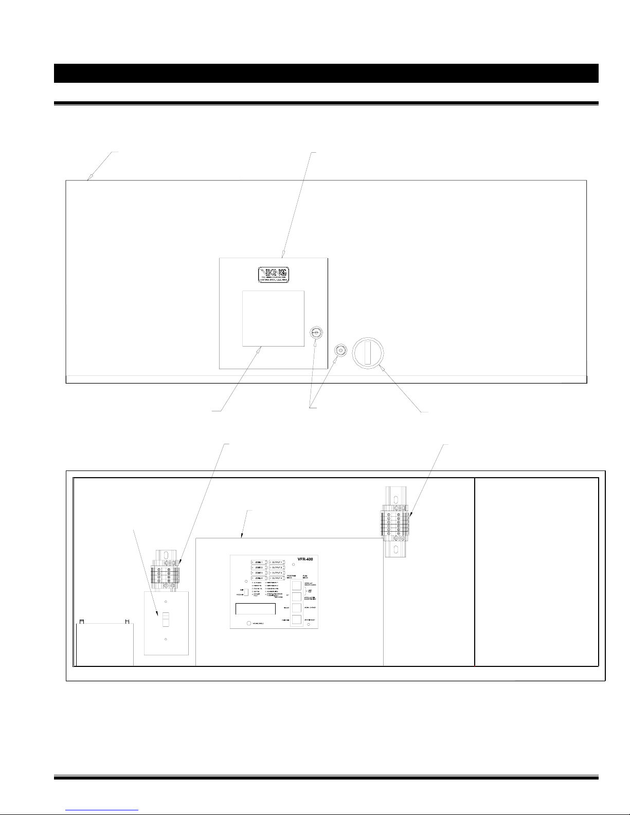
TOTALPAC2 Page 3 of 8
TOTALPAC2 Integrated Fire Protection System
Control Section
Figure 1 - Cabinet door assembly:
Control section hinged door
(recessed hinges on top)
Control Panel
annunciator window
"TBB" field terminal strip
for 120 / 220 Vac Power Supply
(under protective cover)
Releasing panel controls
access door (stainless steel)
Door Lock
(with key alike keys)
Flush door handle
"TBC" field terminal strip
for Los Angeles & Chicago option
FM-086V-0-19
Air compressor
isolatin switch (E15)
Emergency
batteries
NOTE: TBB field terminal strip and Air compressor isolation switch (E15) only with Air Supply Style A air
Figure 2 - Control equipment layout:
Typical control panel
motherboard placement.
FM-086V-0-20
FM-086G-0-29C
Page 46
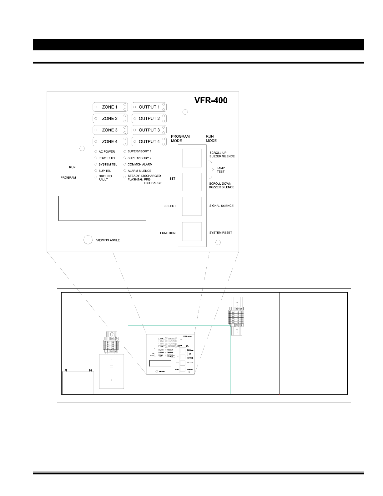
Page 4 of 8 TOTALPAC2
TOTALPAC2 Integrated Fire Protection System
Control Section
Figure 3 - Detail of VFR-400 Panel control section:
Emergency
batteries
FM-086G-0-29C
FM-086V-0-21
Page 47
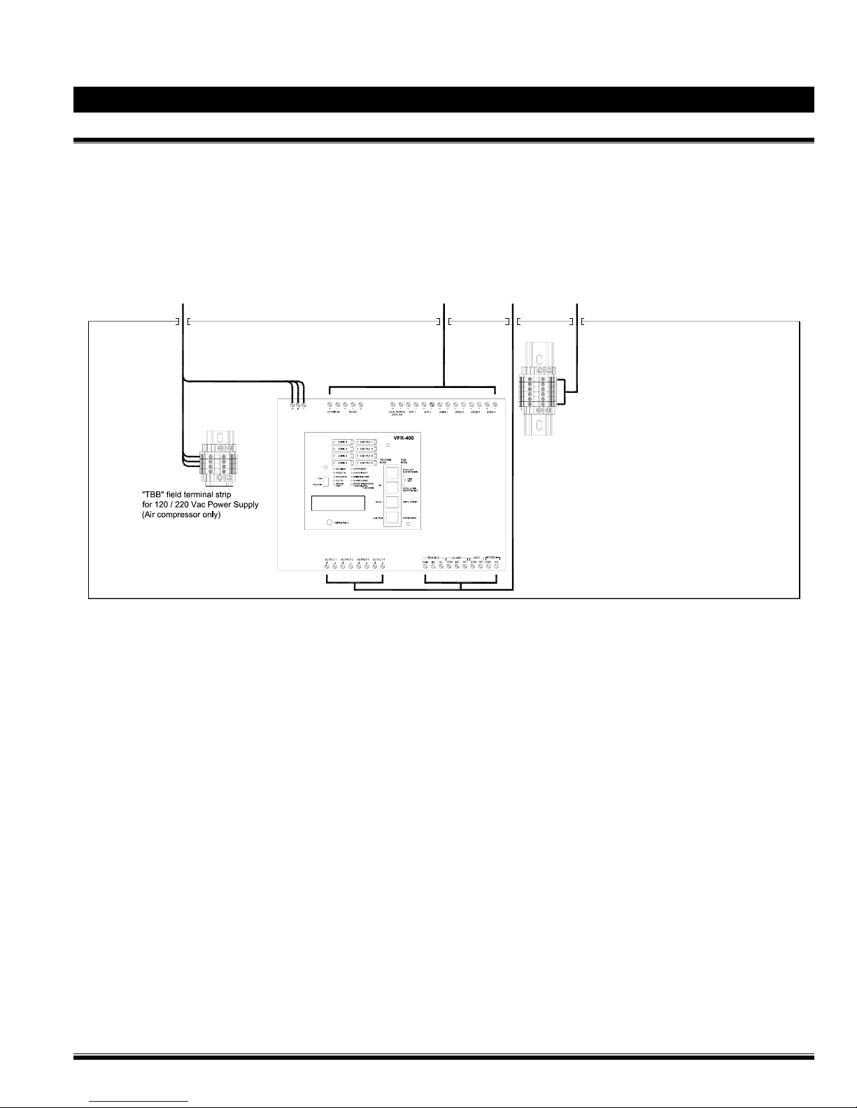
TOTALPAC2 Page 5 of 8
TOTALPAC2 Integrated Fire Protection System
Control Section
Figure 4 - Detail of VFR-400 wiring routing:
AC POWER
120 / 220 Vac Power Supply
(Control panel only)
NAC Circuits
Supervisory / Detection24Vdc / Ann.
POWER LIMITED CIRCUITS
"TBC" field terminal strip
for Los Angeles & Chicago option
Dry contacts
FM-086V-0-22
FM-086G-0-29C
Page 48

Page 6 of 8 TOTALPAC2
TOTALPAC2 Integrated Fire Protection System
Control Section
This page was intentionally left blank
FM-086G-0-29C
Page 49

TOTALPAC2 Page 7 of 8
TOTALPAC2 Integrated Fire Protection System
Control Section
2- Control Section without control panel.
2.1 Product Description
When the T
panel, such as in retrofit applications where the unit is
connected and controlled by a central control panel
already installed in the building or premises.
When such is the case, the top control section of the
OTALPAC2 is not provided and is replaced by a field
T
wiring junction box (See Figure 1 for details). All electrical
components in the trim (pressure switches, supervisory
switches, etc.) are factory wired to a terminal strip (TBA)
for contractor's field wiring. The junction box is provided
with a cover plate maintained in place by 4 screws and
contains the wiring schematic on it's internal face.
Junction box has 4 knock-outs for contractor field wiring.
2.2 Remote Controlled T
Panel)
The installing contractor should make sure the remote
control panel is both listed and programmed to handle the
required sequence of operation necessary t o operate the
automatic sprinkler system. Refer to GENERAL
DESCRIPTION Section, appropriate standards and
Authority Having Jurisdiction for additional information.
2.3 Technical Data
Cabinet:
Steel enclosure: Refer to Cabinet Data Sheet for further
details.
Environment (electrical section):
Temperature: 32
Humidity: 85% Relative Humidity (non-condensing) at
o
90
F (32oC) maximum.
AC Power:
The unit may be provided with an air compressor . Refer to
the appropriate Field Wiring Diagram in "Programming
Section" to determine applicable power requirements.
Wire size: minimum #14 AWG with 600 Volt insulation.
OTALPAC2 unit is provided without any control
OTALPAC2 (without Control
o
F. (0oC) to 120oF (48oC)
Note: This T
Integrated Control Panel, which is supplied by others.
Contractor should make sure the control panel supplied to
control this system complies with the sequence of
operation described in the programming Section. The
remote control panel shall also be listed for releasing
service and be compatible for supervising N.O. contact
devices and operating the 24 Vdc/10Wdc solenoid v alv e of
the system if applicable.
OTALPAC2 Unit has been provided without an
FM-086G-0-29C
Page 50
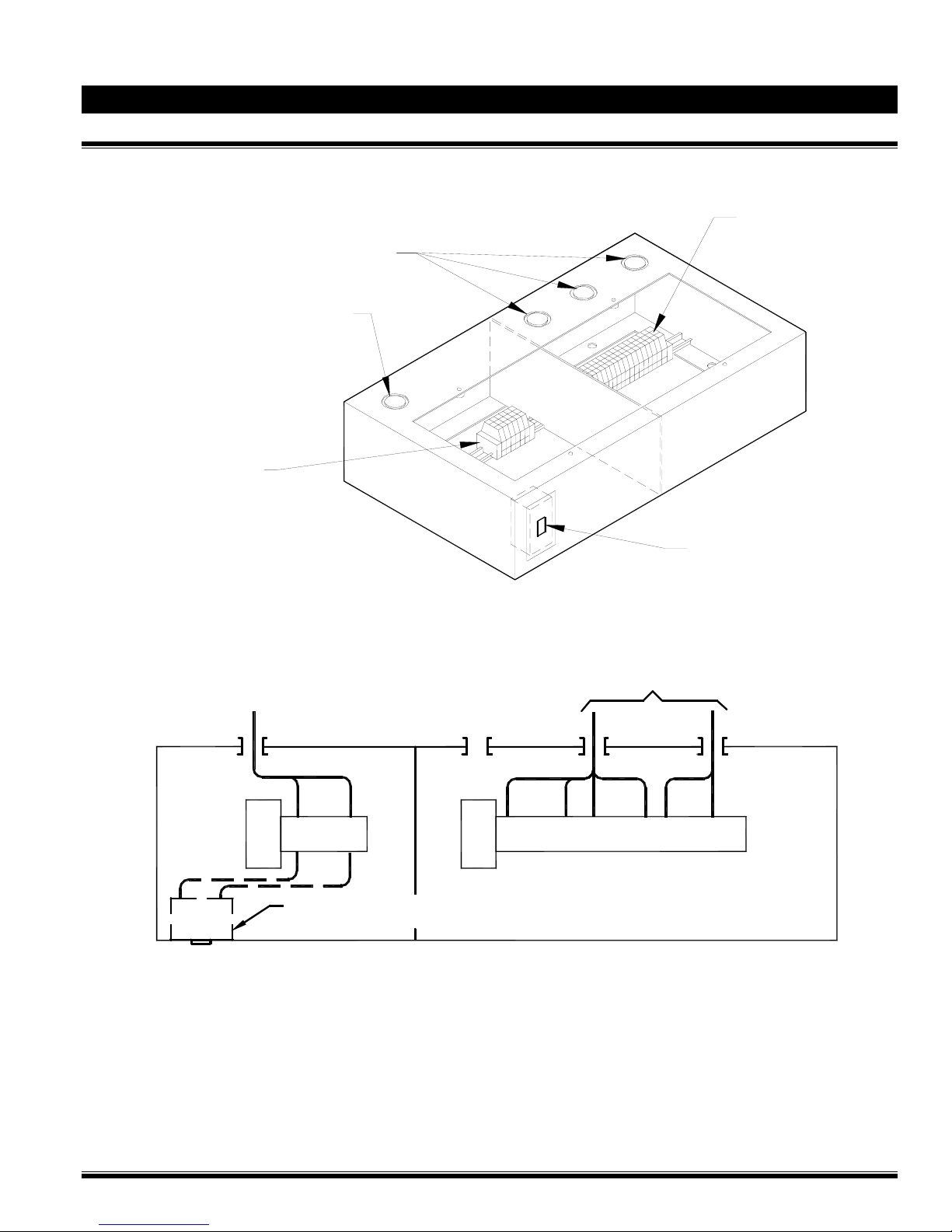
Page 8 of 8 TOTALPAC2
TOTALPAC2 Integrated Fire Protection System
Control Section
Figure 1: Detail of contractor wiring junction box:
TBA Field Wiring
7/8" & 1 1/4" Knockouts
for low voltage field wiring
7/8" & 1 1/4" Knockout
for 120/250Vac power feed wiring
TBB Field Wiring
Terminal Strip
Terminal Strip
g
w
d
.
D
9
2
-
0
-
Q
2
7
0
-
M
F
NOTE: Junction box shown with coverplate
removed for clarity. See Figure 2 for wiring
routing.
Air Compressor or Excess
Pressure Pump Isolation Switch
(when applicable)
Figure 2 - Wiring routing:
AC Power
Power Limited Circuits
120V-60Hz or 220V-50Hz
L1 Flow
TBB
Air Compressor or Excess Pressure Pump
Isolation Switch when applicable
(factory wired)
Detection
TBA
Supervisory
Release
(if applicable)
FM-072Q-0-52 D.dwg
Wiring shown indicates typical Wiring Routing for Power-Limited circuits. Refer to Field Wiring Diagram in "Program ming Secti o n"
for additional details.
FM-086G-0-29C
Page 51

TOTALPAC2 Page 1 of 12
TOTALPAC2 Integrated Fire Protection System
Deluge System - Programming & Field Wiring Diagram
1- Remote Controlled, Pneumatic Release
The TOTALPAC2 Unit without control p anel is factor y wired for
the following configuration:
f Deluge System with Pneumatic Release
This T
Integrated Control Panel since its dry contacts are
supervised by a remote panel. Contractor should m ake sure
the control panel supplied to control this system complies
with the sequence of operation described in MECHANICAL
SECTION. The remote control panel shall also be Listed and
be compatible for supervising sprinklers supervisory and
alarm contact devices. Refer to FIELD WIRING DIAGRAM
for more details. Make sure the system will perform as
required and is tested to confirm it meets all requirements.
Note: All field wiring should be terminated in the contractor
OTALPAC2 Unit has been provided without an
junction box and terminals provided (TBA and TBB) as
shown on the FIELD WIRING DIAGRAM. No connection
should be made directly in the trim components as this
would void warranty and might prevent the normal
operation of the unit.
Operation – Deluge
When a fire occurs, at least one pilot head reaches its trip
point. The pilot line pressure is released and the pneumatic
actuator is then automatically activated. The system alarm
audible devices sound and, if desired, can be silenced
manually. The operation of a pilot head will allow the water
to escape from the priming chamber of the deluge valve.
The clapper of the deluge valve opens, filling the outlet
chamber and flooding the entire area covered by the open
sprinklers and/or nozzles, causing the closing of the
waterflow pressure switch contact. Water flow audible
devices and the water motor gong (if installed) will sound.
The sprinkler system will continue to operate until t he main
water supply control valve is manually closed.
1. Pilot Line Air Pressure Drop
Any leak or opening in the system pilot line network which
allows supervisory air pressure to drop below 25 psi on
175 psi systems (45 psi for 250 psi systems) causes the
opening of the Low Pressure Switch contact.
2. System Manual Operation
Manual opening of the deluge valve by the operation of
the manual emergency release valve causes the water
flow switch to operate.
Note: The same seq uence is obtained with the operation
of the alarm test valve, but the deluge valve is kept
closed.
3. Supervisory of the Valves
An abnormal position of a valve will cause the closing o f
the Valve Supervisory Switch contact. Both the Water
Supply Control Valve and the optional Shut-off Valve are
supervised.
FM-086G-0-38E
Page 52
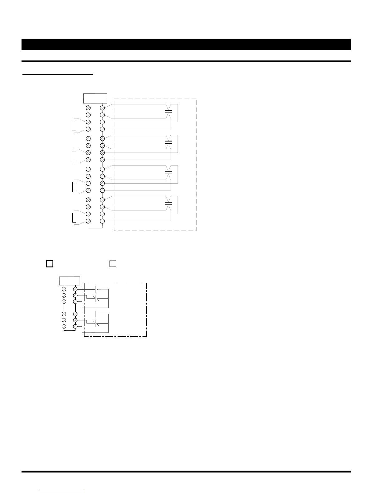
Page 2 of 12 TOTALPAC2
TOTALPAC2 Integrated Fire Protection System
Deluge System - Programming & Field Wiring Diagram
Field wiring diagrams
WATER FLOW
PNEUMATIC RELEASE
LOW AIR PRESSURE
MAIN VALVE
TEST VALVE
(OPTIONAL)
LOS ANGELES OPTION CHICAGO OPTION
+
-
EOL
+
-
EOL
+
-
EOL
+
-
EOL
:
TBA
1
2
3
4
5
6
7
8
9
10
11
12
13
14
15
16
WATER FLOW
SWITCH
LOW PRESSURE
SWITCH
MAIN VALVE
SUP'V SWITCH
TEST VALVE
SUP'V SWITCH
FACTORY WIRED DEVICES
NOTES:
- ALL DEVICES ARE SHOWN IN THEIR
NORMAL SUPERVISORY STATE.
- DRY CONTACTS RATINGS:
PRESS. SWITCHES: 2.5 A. 0-30VDC RESISTIVE / 15A. 30 VAC
SUPV. SWITCHES: 0.5 A. 125 VDC RESISTIVE / 10 A. 30 VAC
USE ONLY WITH POWER LIMITED CIRCUITS
- USE END-OF-LINE DEVICES COMPATIBLE WITH THE
FM-072Q-0-26 C
RELEASE CONTROL PANEL USED (NOT INCLUDED).
TBC
N.O.
1
N.C.
2
C
3
N.O.
4
N.C.
5
C
6
FACTORY WIRED DEVICES
Notes:
1. Contacts provided for connection to the building's central
Fire Alarm Panel.
MAIN VALVE
SUPERVISORY
OPTIONAL
TEST VALVE
SUPERVISORY
FM-072Q-0-67 C
FM-086G-0-38E
Page 53

TOTALPAC2 Page 3 of 12
TOTALPAC2 Integrated Fire Protection System
Deluge System - Programming & Field Wiring Diagram
2- Remote Controlled, Hydraulic Release
The TOTALPAC2 Unit without control p anel is factor y wired for
the following configuration:
f Deluge Hydraulic Release
This T
Integrated Control Panel since its dry contacts are
supervised by a remote panel. Contractor should m ake sure
the control panel supplied to control this system complies
with the sequence of operation described in MECHANICAL
SECTION. The remote control panel shall also be Listed and
be compatible for supervising sprinklers supervisory and
alarm contact devices. Refer to FIELD WIRING DIAGRAM
for more details. Make sure the system will perform as
required and is tested to confirm it meets all requirements.
Note: All field wiring should be terminated in the contractor
OTALPAC2 Unit has been provided without an
junction box and terminals provided (TBA and TBB) as
shown on the FIELD WIRING DIAGRAM. No connection
should be made directly in the trim components as this
would void warranty and might prevent the normal
operation of the unit.
Operation – Deluge
When a fire occurs, at least one releasing device reaches its
trip point. The operation of a releasing device will allo w the
water to escape from the priming chamber of the deluge
valve. The clapper of the deluge valve opens, filling the
outlet chamber and flooding the entire area covere d by the
open sprinklers and/or nozzles, causing the closing of the
waterflow pressure switch contact. Water flow audible
devices and the water motor gong (if installed) will sound.
The sprinkler system will continue to operate until t he main
water supply control valve is manually closed.
1. System Manual Operation
Manual opening of the deluge valve by the operation of
the manual emergency release valve causes the water
flow switch to operate.
Note: The same seq uence is obtained with the operation
of the alarm test valve, but the deluge valve is kept
closed.
2. Supervisory of the Valves
An abnormal position of a valve will cause the closing o f
the Valve Supervisory Switch contact. Both the Water
Supply Control Valve and the optional Shut-off Valve are
supervised.
FM-086G-0-38E
Page 54
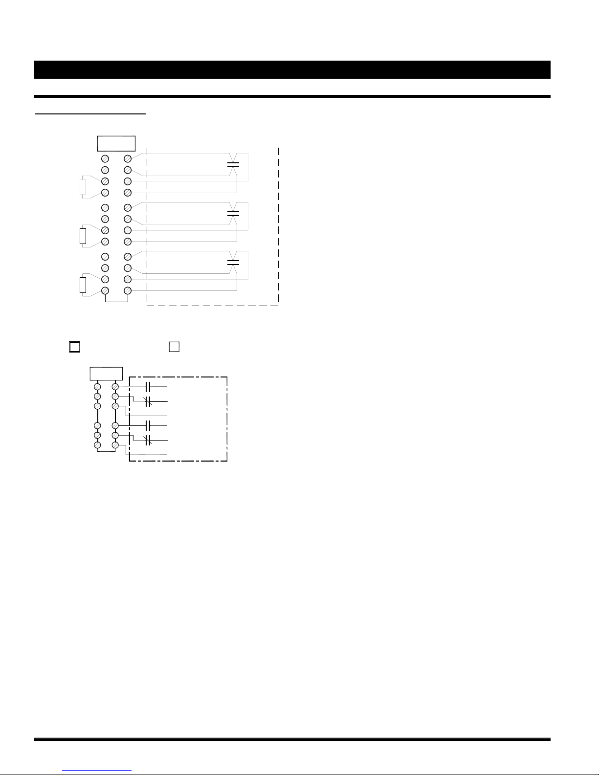
Page 4 of 12 TOTALPAC2
TOTALPAC2 Integrated Fire Protection System
Deluge System - Programming & Field Wiring Diagram
Field wiring diagrams
TBA
+
WATER FLOW
1
2
-
3
EOL
MAIN VALVE
4
+
5
-
6
7
EOL
TEST VALVE
(OPTIONAL)
8
+
9
10
-
11
EOL
12
LOS ANGELES OPTION CHICAGO OPTION
TBC
N.O.
1
N.C.
2
C
3
:
WATER FLOW
SWITCH
MAIN VALVE
SUP'V SWITCH
TEST VALVE
SUP'V SWITCH
FACTORY WIRED DEVICES
MAIN VALVE
SUPERVISORY
NOTES:
- ALL DEVICES ARE SHOWN IN THEIR
NORMAL SUPERVISORY STATE.
- DRY CONTACTS RATINGS:
PRESS. SWITCHES: 2.5 A. 0-30VDC RESISTIVE / 15A. 30 VAC
SUPV. SWITCHES: 0.5 A. 125 VDC RESISTIVE / 10 A. 30 VAC
USE ONLY WITH POWER LIMITED CIRCUITS
- USE END-OF-LINE DEVICES COMPATIBLE WITH THE
RELEASE CONTROL PANEL USED (NOT INCLUDED).
FM-072Q-0-27 B
N.O.
4
N.C.
5
C
6
FACTORY WIRED DEVICES
Notes:
1. Contacts provided for connection to the building's central
Fire Alarm Panel.
OPTIONAL
TEST VALVE
SUPERVISORY
FM-072Q-0-67 C
FM-086G-0-38E
Page 55

TOTALPAC2 Page 5 of 12
TOTALPAC2 Integrated Fire Protection System
Deluge System - Programming & Field Wiring Diagram
3- Remote Controlled, Electric Release
The TOTALPAC2 Unit without control p anel is factor y wired for
the following configuration:
f System with Electric Release
This T
Integrated Control Panel since its dry contacts are
supervised by a remote panel. Contractor should m ake sure
the control panel supplied to control this system complies
with the sequence of operation described in MECHANICAL
TRIM SCHEMATIC. The remote control panel shall also be
Listed and be compatible for supervising sprinklers
supervisory and alarm contact devices and be compati ble for
supervising N.C. 24Vdc Solenoid Valve.
Refer to FIELD WIRING DIAGRAM for more details. Make
sure the system will perform as required and is tested to
confirm it meets all requirements.
Note: All field wiring should be terminated in the contractor
OTALPAC2 Unit has been provided without an
junction box and terminals provided (TBA and TBB) as
shown on the FIELD WIRING DIAGRAM. No connection
should be made directly in the trim components as this
would void warranty and might prevent the normal
operation of the unit.
Operation – Deluge
When the detection system operates, the System Control
Panel activates an alarm and energizes the normally closed
solenoid valve (F1) open. Pressure is released from the
priming chamber faster than it is supplied through restricted
orifice (B3). The deluge valve clapper opens to allow water to
flow into the system piping and alarm devices, causing the
water motor alarm and water flow alarms connected to the
alarm pressure switch to activate. Water will flow from any
open sprinklers and/or spray nozzles on the system.
1. System Manual Operation
Manual opening of the deluge valve by the operation of
the manual emergency release valve causes the water
flow switch to operate.
Note: The same seq uence is obtained with the operation
of the alarm test valve, but the deluge valve is kept
closed.
2. Supervisory of the Valves
An abnormal position of a valve will cause the closing o f
the Valve Supervisory Switch contact. Both the Water
Supply Control Valve and the optional Shut-off Valve are
supervised.
FM-086G-0-38E
Page 56
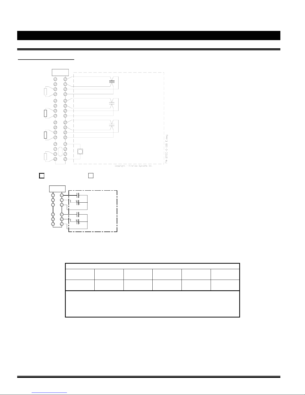
Page 6 of 12 TOTALPAC2
TOTALPAC2 Integrated Fire Protection System
Deluge System - Programming & Field Wiring Diagram
Field wiring diagrams
TBA
+
WATER FLOW
MAIN VALVE
TEST VALVE
(OPTIONAL)
SOLENOID VALVE
SEE NOTES
N.O.
N.C.
C
1
-
2
3
DFL
4
+-5
6
7
DFL
8
+109
-
11
DFL
12
13
+
-
14
15
DFL
16
LOS ANGELES OPTION CHICAGO OPTION
TBC
1
2
3
:
WATER FLOW
SWITCH
MAIN VALVE
SUP'V SWITCH
TEST VALVE
SUP'V SWITCH
N.C. SOLENOID VALVE
S
(See table below for details)
MAIN VALVE
SUPERVISORY
USED ONLY WITH
SHUT-OFF VALVE &
SIGHT-GLASS OPTION
FACTORY WIRED DEVICES
NOTES:
- ALL DEVICES ARE SHOWN IN THEIR
NORMAL SUPERVISORY STATE.
- DRY CONTACTS RATINGS:
PRESS. SWITCHES: 2.5 A. 0-30VDC RESISTIVE / 15A. 30 VAC
SUPV. SWITCHES: 0.5 A. 125 VDC RESISTIVE / 10 A. 30 VAC
USE ONLY WITH POWER LIMITED CIRCUITS
- USE ONLY END-OF-LINE DEVICES COMPATIBLE WITH THE
WITH THE CONTROL PANEL USED (NOT INCLUDED).
- SOLENOID VALVE EOL RESISTOR REQUIRED IN CANADA
ONLY. REPLACE WITH A JUMPER IN OTHER COUNTRIES.
N.O.
4
N.C.
5
C
6
FACTORY WIRED DEVICES
Notes:
1. Contacts provided for connection to the building's central
Fire Alarm Panel.
OPTIONAL
TEST VALVE
SUPERVISORY
FM-072Q-0-67 C
SOLENOID VALVE ELECTRICAL RATINGS
Viking P/N
Description
(De-energized)
Voltage Watts DC Amps
11591 NC 24 VDC 10.0 DC 416 mA
Pressure
Rating
300 psi
(2 068 kPa)
Notes:
1. Solenoid Valve is UL Listed as Fire Protection Special System Water Control Release Service (UL
429A Product category VLTR).
2. Voltage Drop: For proper operation, make sure that voltage at the solenoid valve is at least 85% of
nameplate rating.
FM-086G-0-38E
Page 57

TOTALPAC2 Page 7 of 12
TOTALPAC2 Integrated Fire Protection System
Deluge System - Programming & Field Wiring Diagram
4- Self-Contained, Electric Release
The VIKING VFR-400 Control Panel included with the
OTALPAC2 Unit is factory programmed and wired for the
T
following configurations:
f Deluge, Electric Release
f Deluge, Electric Release NYC
and
f Activation by Zone 1 OR Zone 2
f Activation by Zone 1 (NYC)
f Activation by Zone 1 AND Zone 2 (Cross-zoned)
f Activation by Zone 4 (Pull Station) for all
configurations
This programming makes sure the system will perform as
required and was factory tested to make sure it meets all
requirements.
Pre-configured programs allows field programming for
possible input/output combinations, of which only three are
available and Listed for the current use of the T
System:
Program #1, Single Hazard, Two Alarm Zones with One
Manual Station Zone, One Waterflow Zone and
Two Supervisory Zones.
Program #12, Single Hazard, Two Alarm Zones (Cross-
Zoned) with One Manual Station Zone, One
Waterflow Zone and Two Supervisory Zones.
Program #5, Single Hazard, One Alarm Zone with One
Manual Station Zone, One Waterflow Zone and
Three Supervisory Zones. (NYC)
OTALPAC2
Program #1 Output and Relay Circuits Activated by Detection Circuits:
OUTPUT CIRCUITS RELAY CIRCUITS
Program #1 allows the panel to activate the solenoid valve
when EITHER detection Zone 1, Zone 2 OR Zone 4 is
activated.
Program # 12 allows the panel to activate the solenoid valve
when BOTH detection Zone 1 AND Zone 2 are activated
(Cross-zoned) OR Zone 4 only. (Pull Station)
Program #5 allows the panel to activate the solenoid valve
when EITHER detection Zone 1 OR Zone 4 is activated.
WARNING ! Only the three Pre-configured programs
above are Listed/Approved with the present
TOTALPAC2 Unit. Changing for another preconfigured program may eliminate the Fire
Protection capabilities of the system and/or void
Listing/Approval and Warranty. Consult FireFlex
Systems before making any change
Note: The control panel motherboard is factory pre-
wired and programmed for the configuration selected
at the time of purchase. All field wiring should be
terminated as shown on the FIELD WIRING
DIAGRAM.
PROGRAM 1
SINGLE HAZARD
TWO ZONES
INPUT CIRCUITS
SUPERVISORY ZONE 1 (Spare) X
SUPERVISORY ZONE 2 (Valve Tamper ) X
DETECTION ZONE 1 X X X
DETECTION ZONE 2 X X X
DETECTION ZONE 3 (Waterflow) X X X
DETECTION ZONE 4 (Pull Station) X X X
ALARM BELL
WATERFLOW BELL
RELEASE SOLENOID
SUPERVISORY BELL
ALARM RELAY
TROUBLE RELAY
WATERFLOW RELAY
X
X
X
X
X
X
X
X
X
SUPERVISORY RELAY
FM-086G-0-38E
Page 58

Page 8 of 12 TOTALPAC2
TOTALPAC2 Integrated Fire Protection System
Deluge System - Programming & Field Wiring Diagram
Program #12 Output and Relay Circuits Activated by Detection Circuits:
OUTPUT CIRCUITS RELAY CIRCUITS
PROGRAM 12
SINGLE HAZARD
CROSS ZONED
ALARM BELL
WATERFLOW BELL
RELEASE SOLENOID
SUPERVISORY BELL
ALARM RELAY
TROUBLE RELAY
WATERFLOW RELAY
INPUT CIRCUITS
SUPERVISORY ZONE 1 (Valve Tamper) X
SUPERVISORY ZONE 2 (Air) X
DETECTION ZONE 1 X X
DETECTION ZONE 2 X
DETECTION ZONE 3 (Waterflow) X X
DETECTION ZONE 4 (Pull Station) X X X
BOTH
X
Program #5 Output and Relay Circuits Activated by Detection Circuits:
OUTPUT CIRCUITS RELAY CIRCUITS
X
X
X
X
X
X
X
X
X
SUPERVISORY RELAY
PROGRAM 5
SINGLE HAZARD
TWO ZONES
NYC
INPUT CIRCUITS
SUPERVISORY ZONE 1(Valve Tamper) X X
SUPERVISORY ZONE 2 (Supervisory) X X X X
DETECTION ZONE 1 (Detection) X X X X
DETECTION ZONE 2 (Supervisory) X X
DETECTION ZONE 3 (Waterflow) X X
DETECTION ZONE 4 (Pull Station) X X X X
ALARM BELL
Operation
When a fire occurs, at least one detector reaches its trip
point. One detection circuit is then automatically activated (in
crossed zones mode, both detection zones have to be
activated) OR the activation of Zone 4 (pull station). The
system alarm audible devices sound and, if desired, can be
silenced manually. The normally closed (N.C.) solenoid
valve of the system is energized, allowing the water to
escape from the priming chamber of the deluge valve. The
clapper of the deluge valve opens, filling the outlet chamber
and flooding the entire area covered by the sprinklers and
nozzles. System waterflow audible devices and the water
motor gong (if installed) will sound.
SUPERVISORY BELL
RELEASE SOLENOID
TROUBLE BELL
ALARM RELAY
TROUBLE RELAY
X
X
X
X
X
WATERFLOW RELAY
X
X
X
SUPERVISORY RELAY
WARNING ! The sprinkler system will continue to
operate until the main water inlet valve is manually
closed.
FM-086G-0-38E
Page 59
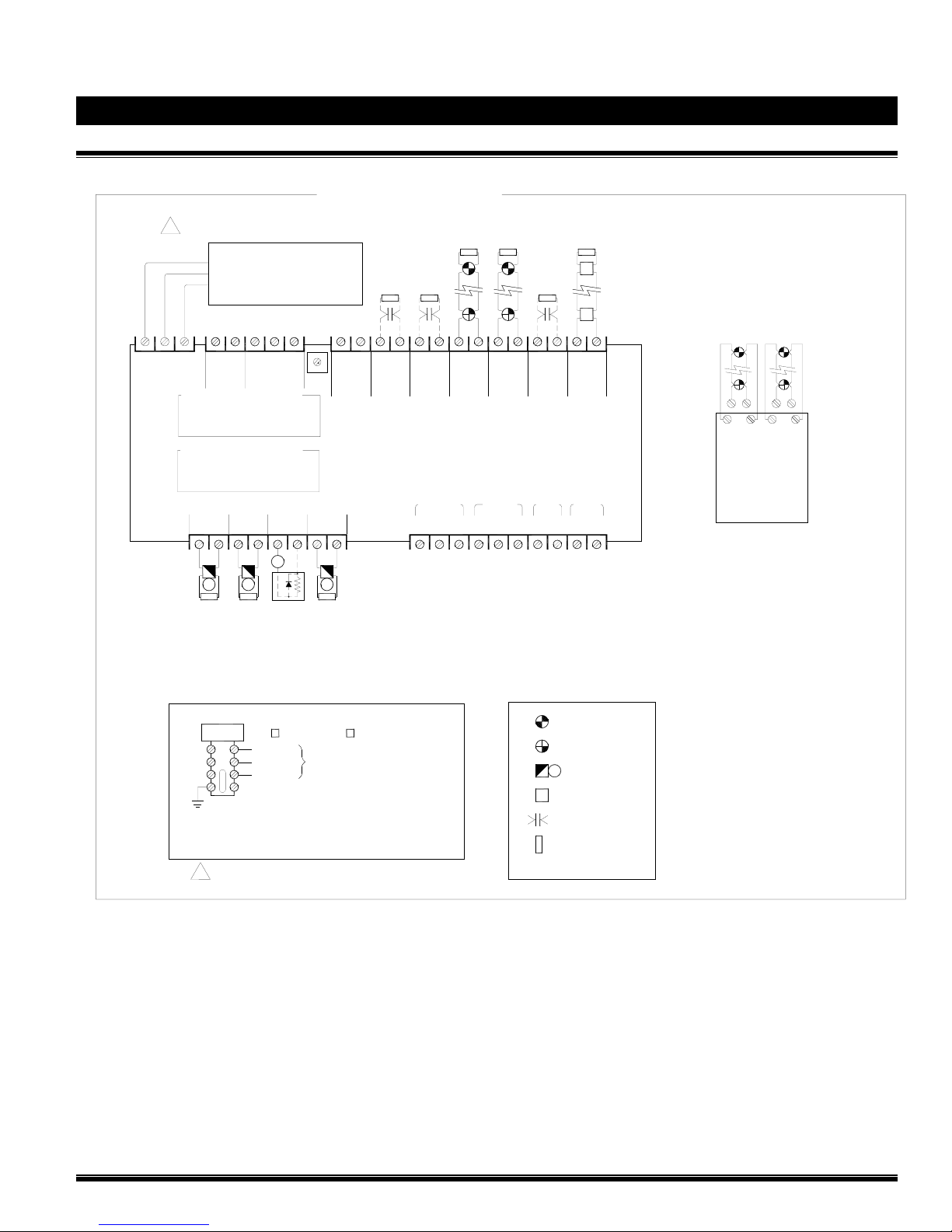
TOTALPAC2 Page 9 of 12
TOTALPAC2 Integrated Fire Protection System
Deluge System - Programming & Field Wiring Diagram
FIELD WIRING DIAGRAMS
An individual branch circuit shall be required
!
for the supply of the control panel power source
AC POWER SUPPLY
120 VAC, 60Hz / 220VAC, 50Hz
CIRCUIT IS NON-POWER LIMITED
AND SUPERVISED
EOL
EOL
-
+
+
EOL
EOL
-
+
+
-
-
+
+
5.1K, 1/4W
ELR (Typical)
EOL
-
EOL
-
+
-
+
M
-
-
+
M
N
LG
Program #/1 Factory pre-wired Zones:
Program #12 Factory pre-wired Zones:
-
+
non reset.
SUP.1=Main valve and/or Shutt-off valve
ZONE 3=Waterflow
OUT 3=Releasing Solenoid
SUP.2=Main valve and/or Shutt-off valve
ZONE 3=Waterflow
OUT 3=Releasing Solenoid
OUT 1OUT 2OUT 3OUT 4
-
RS-485 24VDC
+
+
-
-
0
+
S+
5
1
4
2
3
AUX.
POWER
24VR DC
+
-
S
+
-
-
-
+
+
SUP.2SUP.1
Input Wiring in Class B (style B)
TROUBLE
TB102
COM
TB1
8
7
9
6
Auxiliary dry contact relay outputs
EOL EOL
5.1K, 1/4W
ELR (Typical)
EOL DIODE
ASSY
EOL
Output Wiring in Class B (style Y)
INPUT POWER SOURCE
TBB
1
2
3
4
Wiring size: Minimum 14 AWG with 600V Insulation.
120Vac, 60Hz 220Vac, 50 Hz
LINE
NEUTRAL
GROUND
AIR COMPRESSOR
1 HP Maximum
Wiring of 120/220Vac Air Compressor
Power Source
Branch circuit for air compressor shall not be the same
!
as the control panel power source
Power Limited (supervised) Initiating Device Circuits
Detection Zone 1, 2, 3, and 4.
Max. loop resistance: 100 ohms
End of line: 5.1K ohms, 1/4W
Leave ELR (provided) on all unused circuits.
Refer to Device Compatibility in the VFR-400 Control Panel
Manual.
Power Limited (supervised) Initiating Device Circuits
Supervision Zone 1, and 2.
Max. loop resistance: 100 ohms
End of line: 5.1K ohms, 1/4W
Leave ELR (provided) on all unused circuits.
For dry contact supervisory devices such as tamper, low air, or
high air switches. (Class-B only)
-
ALARM
COM
+
ZONE 2
NO
-
NC
+
ZONE 3
SUPV
COM
NO
+
ZONE 4
WATER
FLOW
COM
-
NO
+
ZONE 1
NC
-
rated 3A at 30Vdc (resistive)
SMOKE DETECTOR
HEAT DETECTOR
NOTIFICATION BELL
M
MANUAL PULL STATION
DRY CONTACT DEVICE
END OF LINE DEVICE
EOL
Legend
Power Limited (supervised) Notification Appliance Circuits
Output Circuit 1, 2, 3, and 4
Maximum operating voltage: 27Vdc (ripple: 0.3Vdc)
Maximum usable current per circuit: 1.0A
Total current available (all circuits): 2.5A
Polarity is reversed in supervisory condition.
Leave ELR (provided) on all unused circuits.
Refer to Device Compatibility in the VFR-400 Control Panel
Manual.
Auxiliary Power 24Vdc Regulated Source
Total current available: 0.2A
Resettable for 4 wires smoke detectors
TB101
-
NO
TB103
Wiring in Class A (style D)
-
+
+
++--
ZONE 1
Each CA2Z will convert
two Class-B Zones into
Class-A Zones
Note: ELR, are not
required on Class-A
-
+
-
-
+
ZONE 2
-+
-+
two
FM-086V-0-26B
FM-086G-0-38E
Page 60
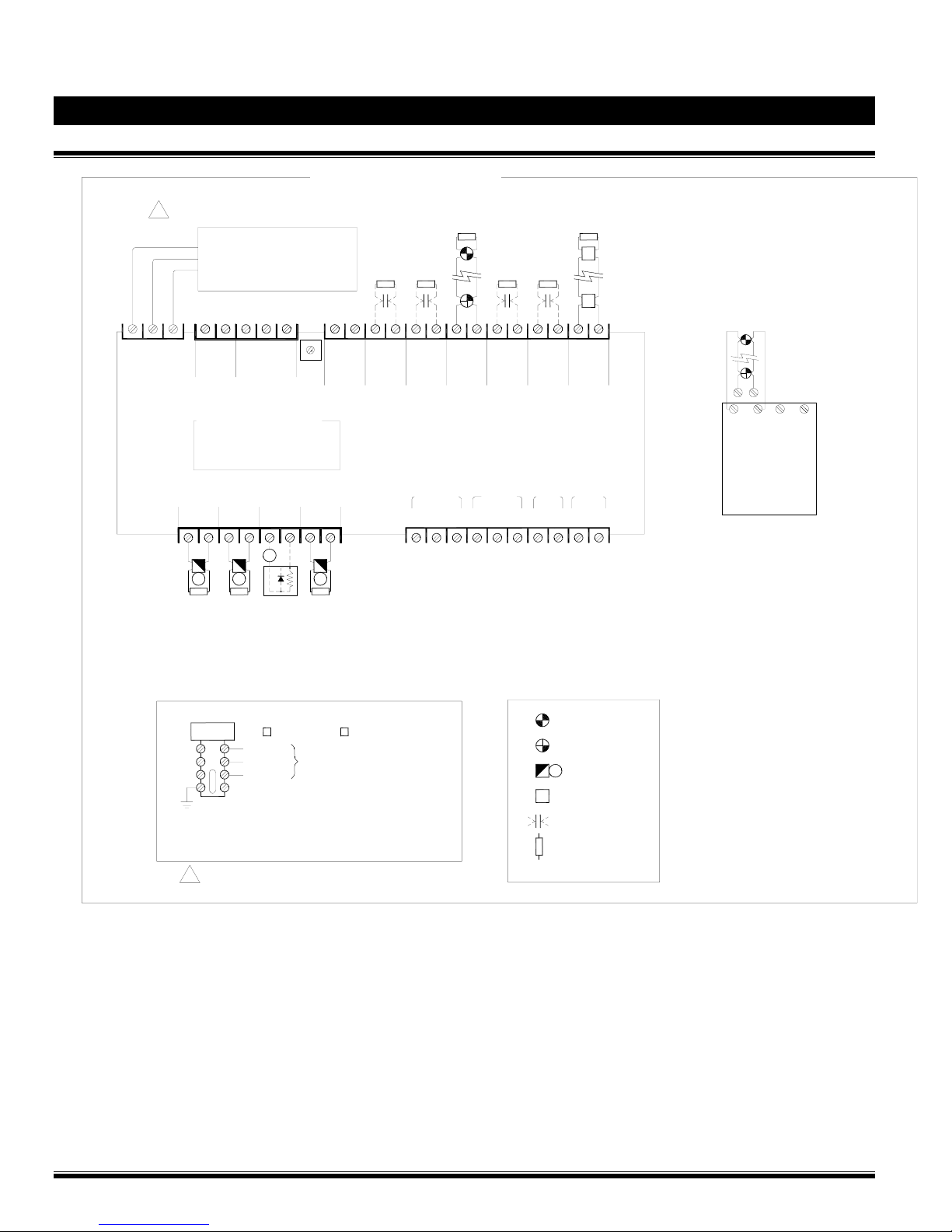
Page 10 of 12 TOTALPAC2
TOTALPAC2 Integrated Fire Protection System
Deluge System - Programming & Field Wiring Diagram
FIELD WIRING DIAGRAMS
An individual branch circuit shall be required
!
for the supply of the control panel power source
AC POWER SUPPLY
120 VAC, 60Hz / 220VAC, 50Hz
CIRCUIT IS NON-POWER LIMITED
AND SUPERVISED
EOL
-
+
EOL
EOL
-
+
+
-
-
+
+
EOL
5.1K, 1/4W
ELR (Typical)
-
+
EOL
-
+
M
EOL
-
-
+
M
NYC
TB1
8
7
9
6
N
LG
-
+
non reset.
Program #5 / Factory pre-wired Zones:
SUP.1=Valve Tamper
SUP.2=Low Air (n/a on Deluge)
ZONE 2=Low Air Alarm (n/a on Deluge)
ZONE 3=Waterflow
OUT 3=Releasing Solenoid
OUT 1 OUT 2 OUT 3 OUT 4
+
-
EOL EOL
5.1K, 1/4W
ELR (Typical)
+
-
-
RS-485 24VDC
-
S
EOL DIODE
ASSY
0
S+
+
5
1
4
2
3
AUX.
POWER
24VR DC
+
+
-
TB102
EOL
Output Wiring in Class B (style Y)
INPUT POWER SOURCE
TBB
1
2
3
4
Wiring size: Minimum 14 AWG with 600V Insulation.
120Vac, 60Hz 220Vac, 50 Hz
LINE
NEUTRAL
GROUND
AIR COMPRESSOR
1 HP Maximum
Wiring of 120/220Vac Air Compressor
Power Source
Branch circuit for air compressor shall not be the same
!
as the control panel power source
-
+
+
SUP.2SUP.1
+
ZONE 1
-
+
ZONE 2
-
+
ZONE 3
-
-
Input Wiring in Class B (style B)
NC
ALARM
COM
NO
NC
SUPV
COM
TROUBLE
COM
NO
Auxiliary dry contact relay outputs
rated 3A at 30Vdc (resistive)
M
EOL
+
ZONE 4
WATER
FLOW
COM
TB101
-
NO
-
NO
SMOKE DETECTOR
HEAT DETECTOR
NOTIFICATION BELL
MANUAL PULL STATION
DRY CONTACT DEVICE
END OF LINE DEVICE
Legend
TB103
-
+
-
+
+-
ZONE 1
convert Zone 1 & Zone 2
ZONE 2
-+ -+
Included CA2Z will
Class-B Zones into two
Class-A Zones
Note: ELR, are not
required on Class-A
Wiring in Class A (style D)
FM-086V-0-25B
Power Limited (supervised) Initiating Device Circuits
Detection Zone 1, 2, 3, and 4.
Max. loop resistance: 100 ohms
End of line: 5.1K ohms, 1/4W
Leave ELR (provided) on all unused circuits.
Refer to Device Compatibility in the VFR-400 Control Panel
Manual.
Power Limited (supervised) Initiating Device Circuits
Supervision Zone 1, and 2.
Max. loop resistance: 100 ohms
End of line: 5.1K ohms, 1/4W
Leave ELR (provided) on all unused circuits.
For dry contact supervisory devices such as tamper, low air, or
high air switches. (Class-B only)
FM-086G-0-38E
Power Limited (supervised) Notification Appliance Circuits
Output Circuit 1, 2, 3, and 4
Maximum operating voltage: 27Vdc (ripple: 0.3Vdc)
Maximum usable current per circuit: 1.0A
Total current available (all circuits): 2.5A
Polarity is reversed in supervisory condition.
Leave ELR (provided) on all unused circuits.
Refer to Device Compatibility in the VFR-400 Control Panel
Manual.
Auxiliary Power 24Vdc Regulated Source
Total current available: 0.2A
Resettable for 4 wires smoke detectors
Page 61
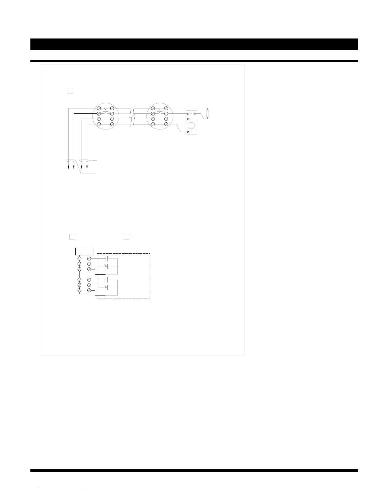
TOTALPAC2 Page 11 of 12
TOTALPAC2 Integrated Fire Protection System
Deluge System - Programming & Field Wiring Diagram
POWER LIMITED 4-WIRES DETECTION CIRCUIT
IDC
++
-++
24Vdc
COM
--
UL Listed
24Vdc 4-Wire
Smoke Detector
To Aux. Power 24VR DC (200mA MAX.)
To Zone 1 or Zone 2
LOS ANGELES OPTION CHICAGO OPTION
TBC
N.O.
1
N.C.
2
C
3
N.O.
4
N.C.
5
C
6
FACTORY WIRED DEVICES
Note:
Contacts provided for connection to the
building's central Fire Alarm Panel.
MAIN VALVE
SUPERVISORY
OPTIONAL
TEST VALVE
SUPERVISORY
IDC
++
-++
24Vdc
COM
--
UL Listed
24Vdc 4-Wire
Smoke Detector
5.1K Ohms
E1
1/4W
R
PAM-4
Power Supervisory
Relay (EOL Relay)
FM-086V-0-12A
FM-086G-0-38E
Page 62
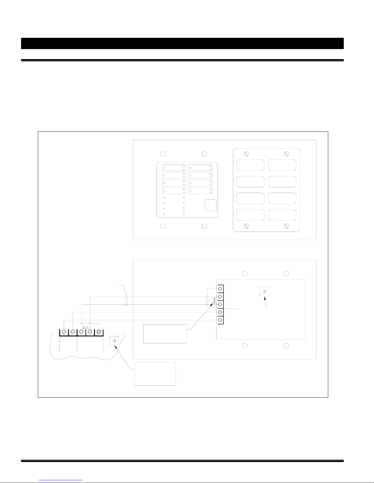
Page 12 of 12 TOTALPAC2
TOTALPAC2 Integrated Fire Protection System
Deluge System - Programming & Field Wiring Diagram
Remote Annunciator RA-4410-RC
The RA-44410-RC remote annunciator is designed to op erate with the VFR-400 releasing control panel. There are 34 LED's to
indicate a change in panel status. There is a buzz er on the annunciator that sounds for any trouble or supervisory condition. The
release control panel supervises and communicates with the annunciator via separate connections for the RS-485 c ommunication
and the 24VDC power requirement of the RA-4410-RC. Separate cables should be used for power and communication. Shielded
cable MUST be used for the RS-485 communication line. Up to four remote annunciator can be connected to one control panel.
RA-4410-RC
ZONE 1
ZONE 2
ZONE 3
ZONE 4
AC POWER
POWER
TROUBLE
SYSTEM
TROUBLE
GROUND
FAULT
OUTPUT 1
OUTPUT 2
OUTPUT 3
OUTPUT 4
SUPERVISORY
SUPERVISORY
TROUBLE
COMMON ALM.
ALM. SILENCE
STEADY : DISCHARGED
FLASHING : PRE-DISCHARGE
LAMP TEST
SILENCE
ZONE 1
OUTPUT 1
OUTPUT 2ZONE 2
OUTPUT 3ZONE 3
OUTPUT 4ZONE 4
SHIELDED CABLE
EOL
TB1
-
+
non reset.
-
S
S+
RS-485 24VDC
VFR-400 main board
S
-
EOL
RS-485
+
+
24VDC
NOTE:
REMOVE 120ohms
8
7
9
6
0
5
1
4
2
3
RESISTOR ON ALL
BUT LAST RA-4410-RC
ANNUNCIATOR
SELECTOR SWITCH,
SHOWN SET FOR 1
ANNUNCIATOR
CONNECTED.
non reset.
8
7
9
6
0
5
1
4
2
3
ANNUNCIATOR
ADDRESS
SWITCH
FM-086V-0-13A
FM-086G-0-38E
Page 63

T
OTALPAC
2
T
OTALPAC
1- Skid mounted Unit
2 Integrated Fire Protection System
Page 1 of 12
System design & Dimensional Data
The T
OTALPAC
measuring 36" x 20" x 6" (91,4 x 50,8 x 15,2 cm) for 1½", 2"
& 3" systems and 46" x 24" x 6" (116,8 x 61 x 15,2 cm) for 4"
& 6" systems (refer to Figures 1 to 5 for dimensions).
All surfaces are rust proof coated, inside and outside, with
fire red, oven baked polyester powder on phosphate base.
IMPORTANT! The T
to be installed where they will be subjected to outdoors
and/or freezing conditions. Refer to environmental data for
additional details. Subjecting the unit to conditions outside
these limitations might hamper the normal operation of the
system.
The skid assembly is pre-assembled and factory tested
under ISO-9001 conditions (refer to following figures for
installation and clearances details).
Note: This skid unit contains only the mechanical section of
the T
OTALPAC
and air supply when applicable are provided by others.
Multiple unit installations are easily achieved by manifolding
units together at their water inlets but drains shall remain
separate and open. Refer to Figure 4 & 5 for additional
details on how to pipe the drains.
2 unit skid is made of sturdy 14 gauge steel,
OTALPAC
2 trim. Electrical connections, control panel
2 skid units are NOT designed
System Size
(Dia.)
1½" 285 192
2" 310 141
3" 440 200
4" 510 231
6" 710 322
Note: Above Shipping Weights are nominal and will change
depending on configuration and options selected.
Shipping weights
Lbs. Kg.
PREACTION
FM-086G-0-48C
Page 64
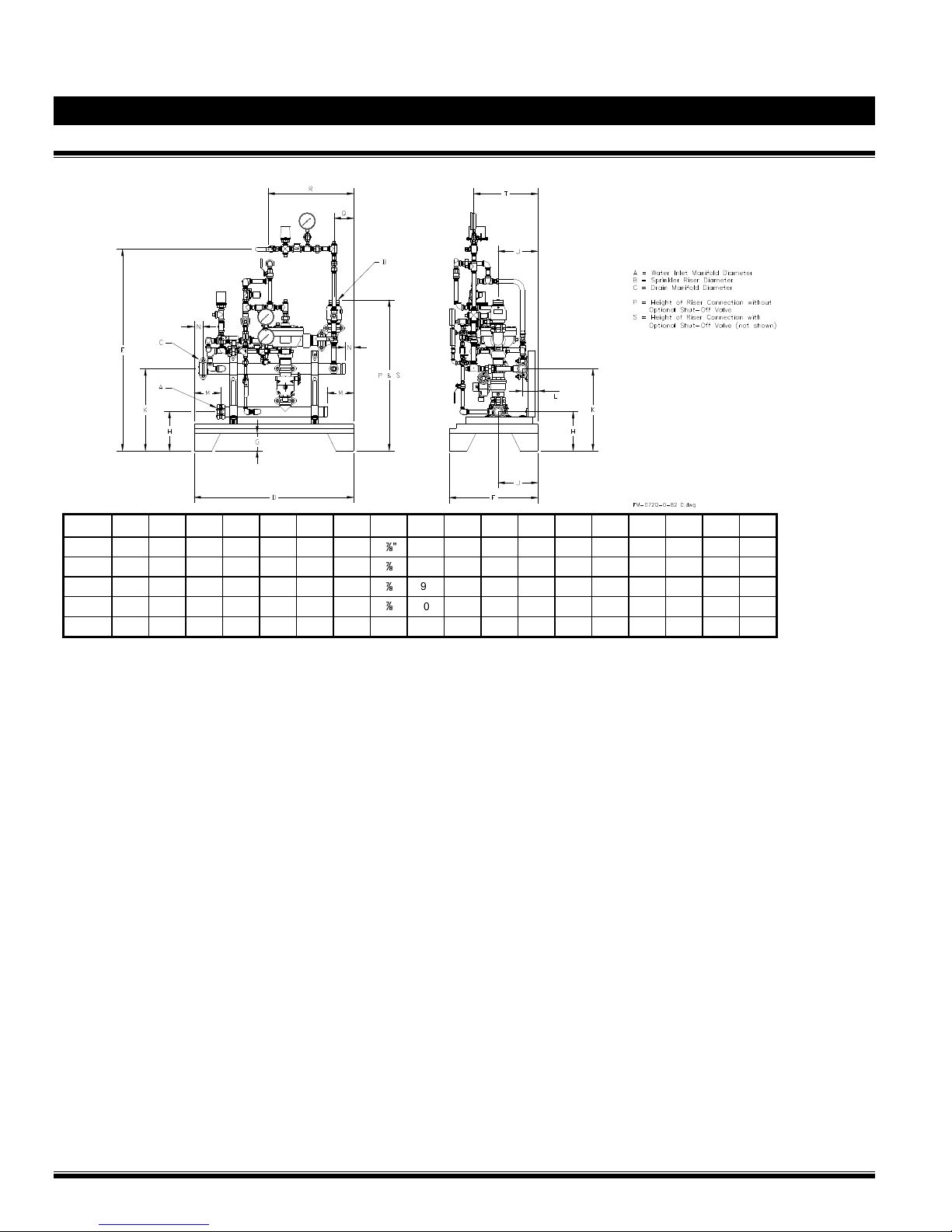
Page 2 of 12
Figure 1 – Dimensions - Preaction:
T
OTALPAC
T
2 Integrated Fire Protection System
System design & Dimensional Data
OTALPAC
2
System
Size
1½"
Note: Some dimensions and actual skid layout may vary depending on options and configuration selected.
A B C D E F G H J K L M N P Q R S T
2" 1½" 2" 36" 46" 20" 4" 8" 9" 18½" 3½" 6" 2" 34½" 5" 19½" 41¾" 13¾"
2"
2" 2" 2" 36" 46" 20" 4" 8" 9" 18½" 3½" 6" 2" 34" 5" 19½" 41¼"
3"
4" 3" 2" 36" 46" 20" 4" 9" 9" 18½" 3½" 6" 2" 38⅜" 5" 19½" 42⅛"
4"
4" 4" 2" 46" 46" 24" 4" 9" 10" 18½" 3½" 6" 2" 39⅝" 6½" 19½" 44¼" 16⅞"
6"
6" 6" 2" 46" 46" 24" 4" 11" 10" 18½" 3½" 6" 2" 48⅝" 6½" 19½" 54½" 21"
14½"
14½"
FM-086G-0-48C
Page 65
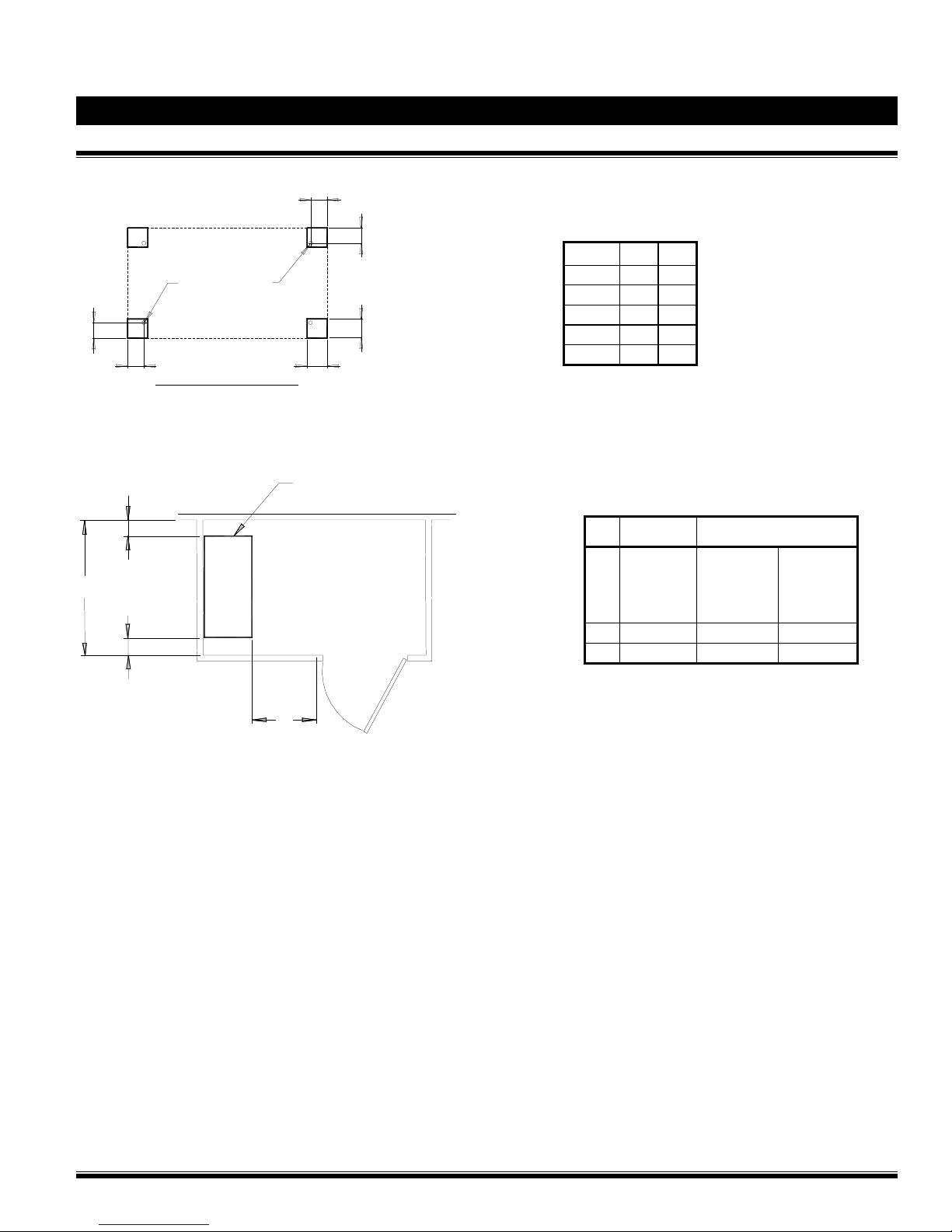
T
OTALPAC
2
T
OTALPAC
2 Integrated Fire Protection System
System design & Dimensional Data
Figure 2 – Dimensions – Anchoring detail:
T
9/16" DIA. (4 HOLES)
T
T
FLOOR ANCHORING TEMPLATE
Figure 3 – Skid clearance detail
B
A
B
U
TotalPac2 Skid
Unit
Page 3 of 12
T
U
FM-072Q-0-86 A.dwg
System
Size
1½"
2"
3"
4"
6"
T U
2¾" 4"
2¾" 4"
2¾" 4"
2¾" 4"
2¾" 4"
Unit Size Minimum Dimension
1 ½"
2"
A
B
C
3"
4"
6"
All 12" 30,5 cm
All 24" 61 cm
60"
60"
60"
70"
70"
152,4 cm
152,4 cm
152,4 cm
177,8 cm
177,8 cm
C
FM-086G-0-48C
Page 66
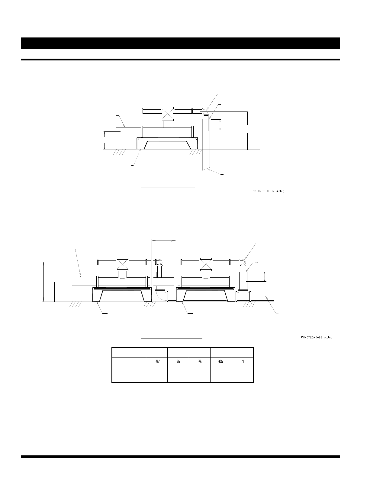
Page 4 of 12
T
OTALPAC
2 Integrated Fire Protection System
System design & Dimensional Data
Figure 4: Open drain details for single unit:
(see dimensions in table below)
Water Supply Pipe
Unit Drain Pipe
(dia. = C)
Air Gap
T
OTALPAC
2
A
TotalPac2 Skid Ass'y
Figure 5: Open drain details for multiple units:
(see dimensions in table below)
Water Supply Pipe
(Can Be Manifolded)
B
A
Single Unit Detail
12" (Min.)
4" Min.
Drain Pipe (pipe diameter
per drain flow calculation)
B
Unit Drain Pipe
(dia. = C)
DO NOT MANIFOLD !
Typical Air Gap
4" Min.
Unit Size: 1½" 2" 3" 4" 6"
Notes:
1. Supply and drain pipes can be connected on either sides of cabinet.
2. All pipes and fittings should meet applicable codes.
3. Actual drain collector diameter shall be determined with detailed hydraulic calculations and is the responsibility of the system
designer.
FM-086G-0-48C
Multiple Units Detail
A
B
C
8" 8" 9" 9" 11"
18½" 18½" 18½" 18½" 18½"
2" 2" 2" 2" 2"
Drain Collector running
TotalPac2 Skid Ass'yTotalPac2 Skid Ass'y
between wall and units
(pipe diameter per
drain flow calculations)
Page 67

T
OTALPAC
2
T
OTALPAC
2 Integrated Fire Protection System
System design & Dimensional Data
2- Cabinet for Remote Controlled Unit
The T
OTALPAC
steel, measuring 36" x 20" x 57" (91,4 x 50,8 x 144,8 cm) for
1½", 2" & 3" systems and 46" x 24" x 57" (116,8 x 61 x 144,8
cm) for 4" & 6" for 4" & 6" systems (refer to Figure 1 for
dimensions).
All surfaces are rust proof coated, inside and outside, with
fire red, oven baked polyester powder on phosphate base.
Cabinet is provided with individual access doors for the
hydraulic and electrical sections and the emergency release
with a neoprene gasket to avoid vibrations.
The field wiring electrical junction boxes is integrated with the
cabinet for connection of All electrical components in the trim
(pressure switches, supervisory switches, etc.) are factory
wired to a terminal strip (TBA) for contractors field wiring.
The junction box is provided with a cover plate maintained in
place by 4 screws and contains the wiring schematic on it's
internal face.
Junction box has 4 knock-outs for contractor field wiring.
Gauges to indicate air, water supply pressure and priming
water pressure are all visible through clear Lexan windows.
2 unit cabinet is made of sturdy 14 gauge
Page 5 of 12
Multiple unit installations are easily achieved by manifolding
units together at their water inlets but drains shall remain
separate and open. Refer to Figure 3 & 4 for additional
details on how to pipe drains.
System Size (in.)
PREACTION
1½" 536 243
2" 561 255
3" 696 316
4" 776 352
6" 991 450
Note: Above Shipping Weights are nominal and will change
depending on configuration and options selected.
Shipping weights:
Lbs. Kg.
IMPORTANT! T
installed where they will be subjected to outdoors
and/or freezing conditions. Refer to environmental
data for additional details. Subjecting the unit to
conditions outside these limitations might hamper
the normal operation of the system.
Cabinet doors are provided with hinges that can easily be
disassembled on site to remove the door assemblies for
servicing. The cabinet assembly is pre-assembled, prewired, and factory tested under ISO-9001 conditions (refer to
Figures 1 & 2 for installation and clearances details).
Note: This cabinet contains only the mechanical section of
the T
OTALPAC
cabinet. The top electrical section is not provided since the
control panel is provided by others. The cabinet is Listed
both with or without the control panel section.
OTALPAC
2 with an electrical junction box on top of the
2 units are NOT designed to be
FM-086G-0-48C
Page 68
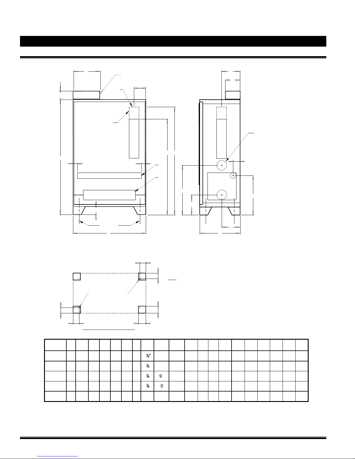
Page 6 of 12
Figure 1 – Dimensions:
V
E
T
OTALPAC
W
Optional
Shut-Off Valve
N
T
2 Integrated Fire Protection System
System design & Dimensional Data
CONTRACTOR WIRING
JUNCTION BOX
B
Q
SPRINKLER RISER
SCH.40 GROOVED OUTLET
N
P
S
C
R
X
OPTIONAL F.D.
CONN. OUTLET
(DRILLED ONLY
WHEN ORDERED !)
SPRINKLER RISER
SCH.40 GROOVED OUTLET
L
OTALPAC
2
T
System
Size
1½"
2"
3"
4"
6"
DRAIN - SCH.40 GROOVED OUTLET
M
T
WATER INLET
SCH.40 GROOVED OUTLET
G
See Note
D
9/16" DIAM. (4 HOLES)
FLOOR ANCHORING TEMPLATE
M
T
U
A
Y
H
T
Note: Access holes provided on
enclosure bottom plate to access
anchoring holes.
A = WATER INLET DIAMETER
B = SPRINKLER RISER DIAMETER
U
C = DRAIN PIPE DIAMETER
K
J
F
FM-072Q-0-08 B.dwg
A B C D E F G H J/R K L M N Q T U V W X Y
2" 1½" 2" 36" 57" 20" 4" 8" 9" 18½" 3½" 6" 2" 5" 2¾" 4" 4" 17" 10" 26"
2" 2" 2" 36" 57" 20" 4" 8" 9" 18½" 3½" 6" 2" 5" 2¾" 4" 4" 17" 10" 25"
4" 3" 2" 36" 57" 20" 4" 9" 9" 18½" 3½" 6" 2" 5" 2¾" 4" 4" 17" 10" 25"
4" 4" 2" 46" 57" 24" 4" 9" 10" 18½" 3½" 6" 2" 6½" 2¾" 4" 4" 17" 10" 25"
6" 6" 2" 46" 57" 24" 4" 11" 10" 18½" 3½" 6" 2" 6½" 2¾" 4" 4" 17" 10" 25"
Notes: Dimension W is nominal and may vary by about ¼.
Dimensions P and S vary with system configuration, refer to the following table for details.
FM-086G-0-48C
Page 69
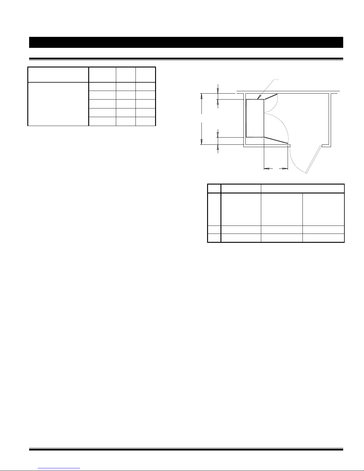
T
OTALPAC
Configuration
Preaction
2
T
OTALPAC
System
Size
1½"
2"
3"
4"
6"
2 Integrated Fire Protection System
System design & Dimensional Data
P S
34½" 41¾"
34" 41¼"
38⅜" 42⅛"
39⅝" 44¼"
48⅝" 54½"
Figure 2 – Cabinet & doors clearance detail
B
A
TotalPac2 Unit
Typical
Mechanical Room
Page 7 of 12
B
C
Unit Size Minimum Dimension
1 ½"
2"
A
B
C
3"
4"
6"
All 12" 30,5 cm
All 24" 61 cm
52"
52"
52"
62"
62"
FM-072Q-0-25 A.dwg
132 cm
132 cm
132 cm
157,5 cm
157,5 cm
FM-086G-0-48C
Page 70
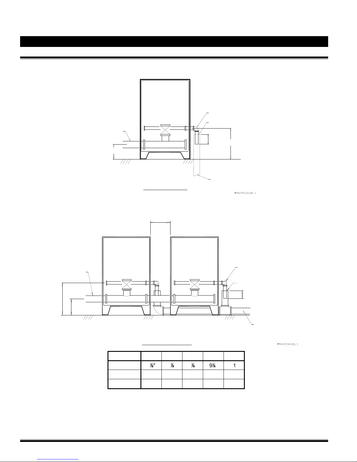
Page 8 of 12
T
OTALPAC
2 Integrated Fire Protection System
System design & Dimensional Data
Figure 3: Open drain details for single unit:
(see dimensions in table below)
Water Supply Pipe
A
Figure 4: Open drain details for multiple units:
(see dimensions in table below)
TotalPac Shown
Without Front Door
Single Unit Detail
12" (Min.)
Unit Drain Pipe
(dia. = C)
Air Gap
4" Min.
Drain Pipe (pipe diameter
per drain flow calculation)
B
T
OTALPAC
2
TotalPac Shown
Without Front Door
Unit Drain Pipe
Water Supply Pipe
(Can Be Manifolded)
B
A
Multiple Units Detail
(dia. = C)
DO NOT MANIFOLD !
Typical Air Gap
4" Min.
Drain Collector running
between wall and units
(pipe diameter per
drain flow calculations)
Unit Size 1½" 2" 3" 4" 6"
A
B
C
Notes:
1. Supply and drain pipes can be connected on either sides of cabinet.
2. All pipes and fittings should meet applicable codes.
3. Actual drain collector diameter shall be determined with detailed hydraulic calculations and is the responsibility of the system
designer.
8" 8" 9" 9" 11"
18½" 18½" 18½" 18½" 18½"
2" 2" 2" 2" 2"
FM-086G-0-48C
Page 71

T
OTALPAC
2
T
OTALPAC
2 Integrated Fire Protection System
System design & Dimensional Data
3- Cabinet for Self-Contained Unit
The T
OTALPAC
steel, measuring 36" x 20" x 71" (91,4 x 50,8 x 180,3 cm) for
1½", 2" & 3" systems and 46" x 24" x 71" (116,8 x 61 x 180,3
cm) for 4" & 6" systems (refer to Figure 1 for dimensions).
All surfaces are rust proof coated, inside and outside, with
fire red, oven baked polyester powder on phosphate base.
Cabinet is provided with individual access doors for the
hydraulic and electrical sections and the emergency release
with a neoprene gasket to avoid vibrations.
Electrical junction boxes are integrated with the cabinet for
connection of detection system, auxiliary contacts and
signaling devices. Knockouts can be drilled by the installing
contractor on-site but have to meet the restrictions indicated
on Figure 3.
Gauges to indicate air, water supply pressure and priming
water pressure are all visible through clear Lexan windows.
2 unit cabinet is made of sturdy 14 gauge
Page 9 of 12
Multiple unit installations are easily achieved by manifolding
units together at their water inlets but drains shall remain
separate and open. Refer to Figure 7 for additional details
on how to pipe drains.
System Size (Dia.)
PREACTION
1½" 610 277
2" 635 288
3" 770 349
4" 856 388
6" 1071 486
Shipping weights:
Lbs. Kg.
IMPORTANT!
installed where they will be subjected to outdoors and/or
freezing conditions. Refer to ENVIRONMENTAL DATA for
additional details. Subjecting the unit to conditions outside
these limitations might hamper the normal operation of the
system.
Cabinet doors are provided with hinges that can easily be
disassembled on site to remove the door assemblies for
servicing. The cabinet assembly is pre-assembled, prewired, and factory tested under ISO-9001 conditions. Refer
to Figure 2 for installation and clearances details.
Note:
electrical section are provided in two separate enclosures,
stacked one on top of the other. The cabinet is Listed both
with or without the control panel section.
T
OTALPAC
The mechanical section of the T
2 units are NOT designed to be
OTALPAC
2 and the
Note:
Above Shipping Weights are nominal and will change
depending on configuration and options selected.
FM-086G-0-48C
Page 72
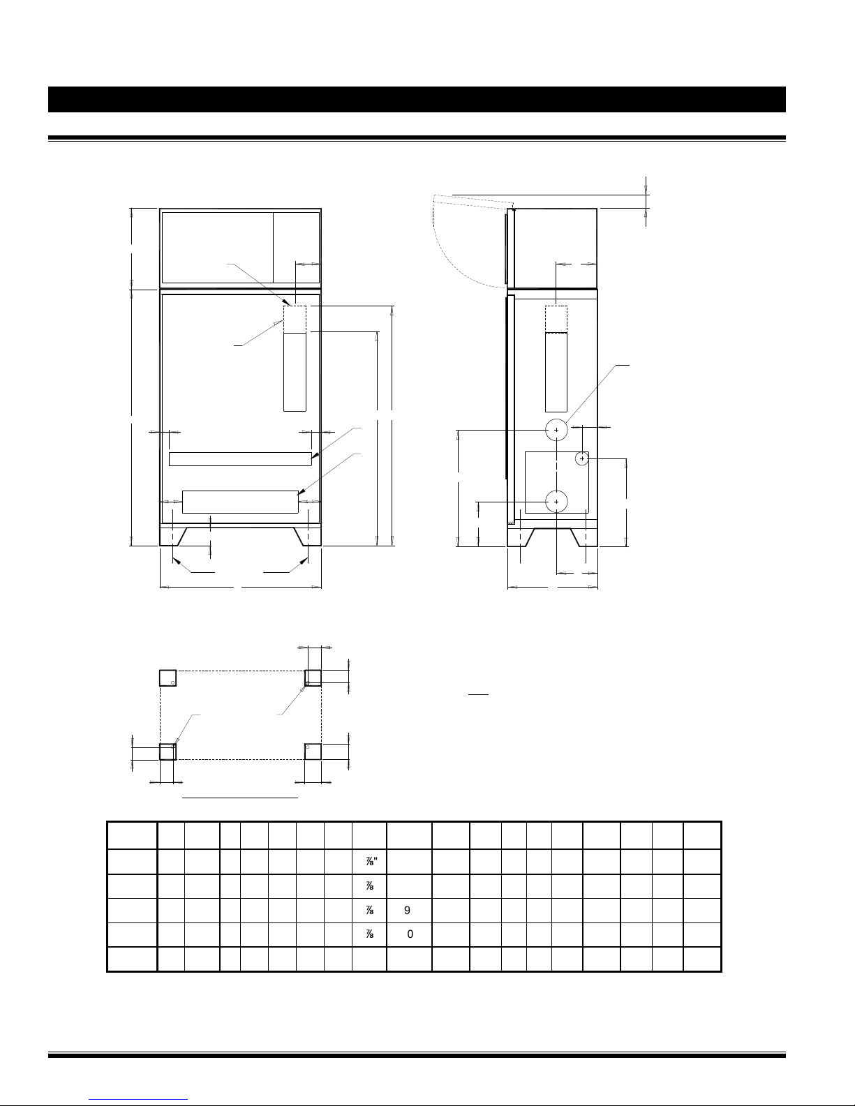
Page 10 of 12
T
OTALPAC
2 Integrated Fire Protection System
T
OTALPAC
2
System design & Dimensional Data
Figure 1 – Dimensions:
V
E
N
DRAIN - SCH.40 GROOVED OUTLET
M
B
OPTIONAL
SHUT-OFF VALVE
WATER INLET
SCH.40 GROOVED OUTLET
G
2" MAX.
Q
SPRINKLER RISER
SCH.40 GROOVED OUTLET
N
M
P
S
C
A
W
H
R
OPTIONAL F.D.
CONN. OUTLET
(DRILLED ONLY
SPRINKLER RISER
SCH.40 GROOVED OUTLET
L
WHEN ORDERED !)
K
T
System
Size
1½"
2"
3"
4"
6"
See Note
D
9/16" DIA. (4 HOLES)
T
FLOOR ANCHORING TEMPLATE
T
T
U
U
Note: Access holes provided on
enclosure bottom plate to access
anchoring holes.
A = WATER INLET DIAMETER
B = SPRINKLER RISER DIAMETER
C = DRAIN PIPE DIAMETER
J
F
FM-072Q-0-21 B.doc
A B C D E F G H J / R K L M N Q T U V W
2" 1½" 2" 36" 57" 20" 4" 8" 9" 18½" 3½" 6" 2" 5" 2¾" 4" 14" 26"
2" 2" 2" 36" 57" 20" 4" 8" 9" 18½" 3½" 6" 2" 5" 2¾" 4" 14" 25"
4" 3" 2" 36" 57" 20" 4" 9" 9" 18½" 3½" 6" 2" 5" 2¾" 4" 14" 25"
4" 4" 2" 46" 57" 24" 4" 9" 10" 18½" 3½" 6" 2" 6½" 2¾" 4" 14" 25"
6" 6" 2" 46" 57" 24" 4" 11" 10" 18½" 3½" 6" 2" 6½" 2¾" 4" 14" 25"
Notes:
Dimension W is nominal and may vary by about ¼.
Dimensions P and S vary with system configuration, refer to the following table for details.
FM-086G-0-48C
Page 73
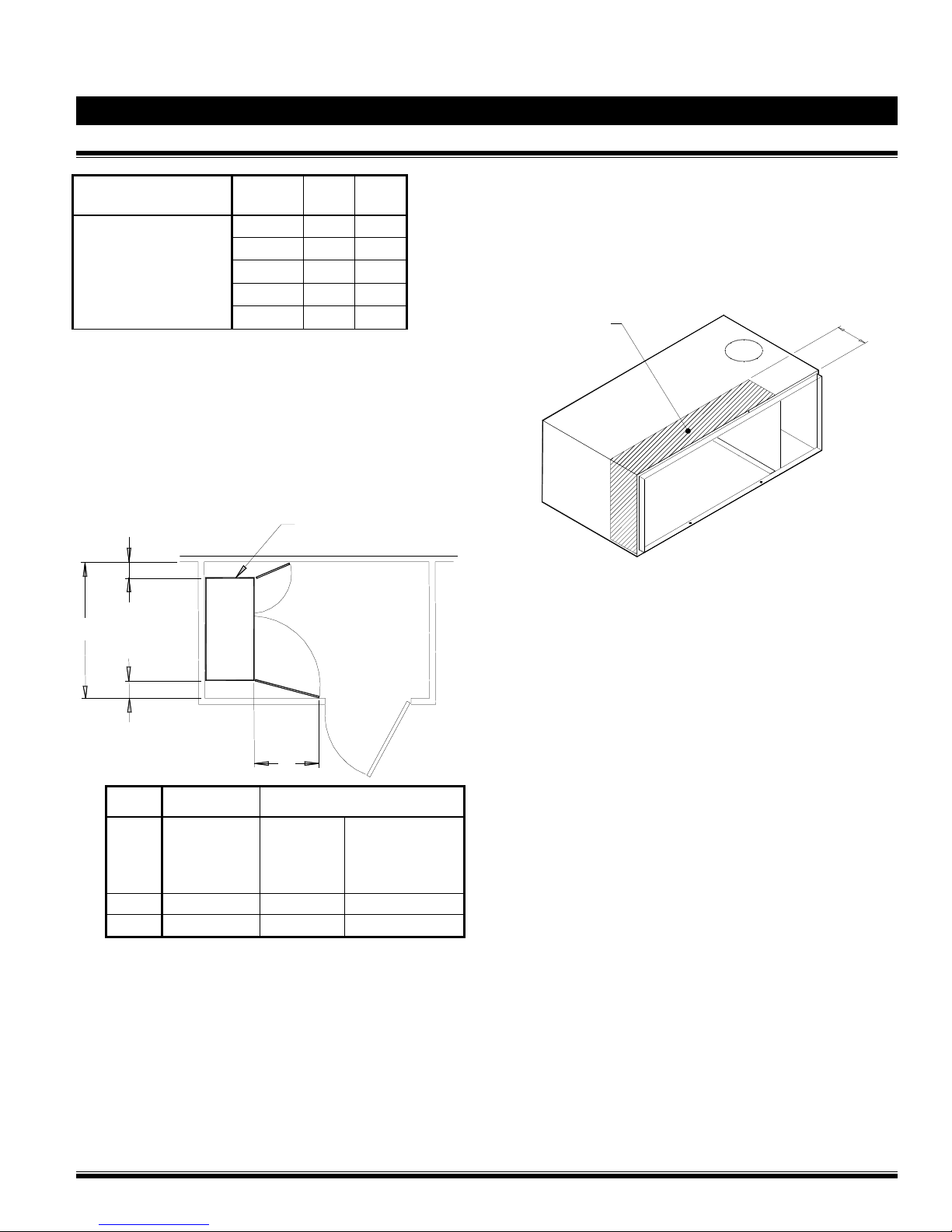
T
OTALPAC
2
T
OTALPAC
2 Integrated Fire Protection System
System design & Dimensional Data
Configuration
Preaction
Figure 2 – Minimum cabinet & doors clearance detail
System
Size
1½"
2"
3"
4"
6"
P S
34½" 41¾"
34" 41¼"
38⅜" 42⅛"
39⅝" 44¼"
48⅝" 54½"
TotalPac2 Unit
Page 11 of 12
Drilling:
When drilling in the cabinet to install wiring conduits or pipes,
avoid the area of the front 6" (15 cm) of the top of the cabinet
since internal wiring is concentrated in that area. Always
avoid drilling into internal components.
Figure 3 – Drilling detail:
"NO DRILL" ZONE
-
0
-
Q
2
7
0
-
M
F
6"
g
w
d
.
A
3
6
B
A
Note: Control cabinet shown without front door.
Hatch pattern indicates zone that should be
avoided when drilling for wiring conduits in enclosure,
viewed from the left front corner of the cabinet.
Wiring Routing:
B
FM-072Q-0-25 A.dwg
Wiring shown in Figure 4 below indicates typical Wiring
Routing for Power Limited Circuits.
Refer to FIELD WIRING DIAGRAM and drilling guide above
for details.
C
Unit Size Minimum Dimensions
A
B
C
1 ½"
2"
3"
4"
6"
All 12" 30,5 cm
All 24" 61 cm
52"
52"
52"
70"
70"
132 cm
132 cm
132 cm
178 cm
178 cm
FM-086G-0-48C
Page 74
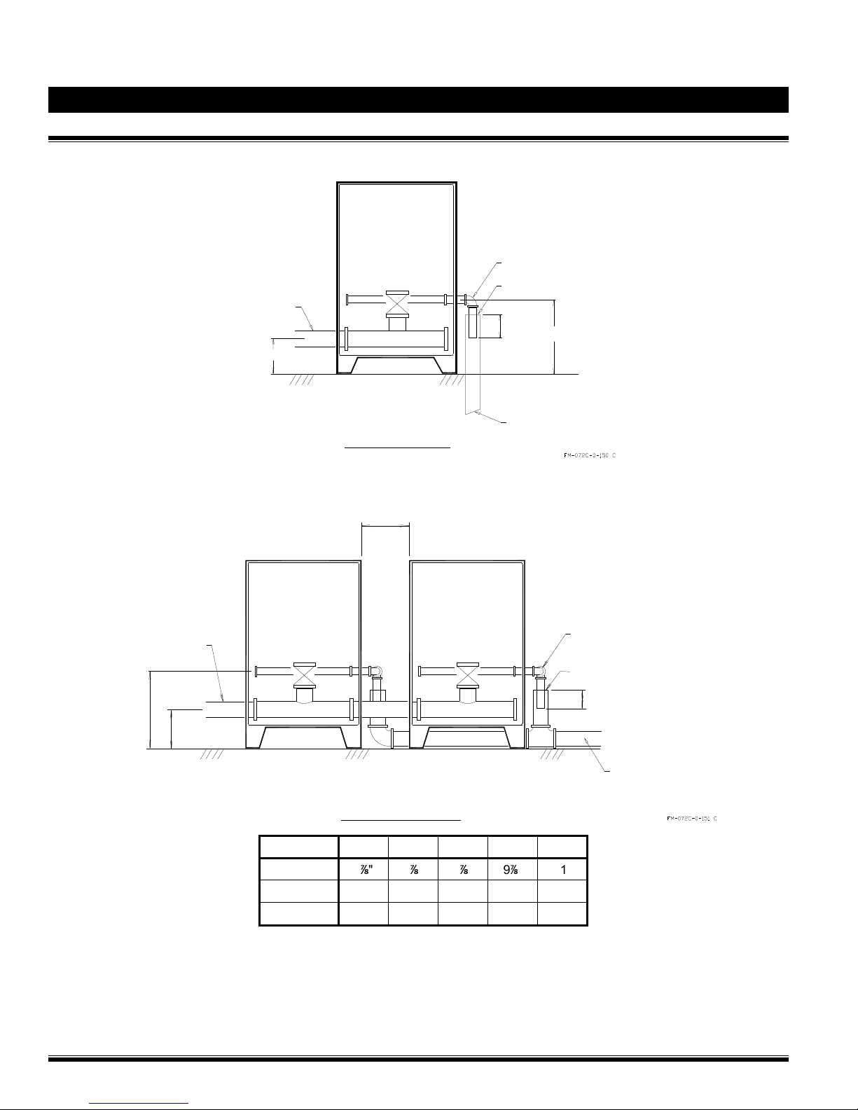
Page 12 of 12
T
OTALPAC
2 Integrated Fire Protection System
System design & Dimensional Data
Figure 5: Open drain details for single unit:
(see dimensions in table below)
Water Supply Pipe
Figure 6: Open drain details for multiple units:
(see dimensions in table below)
A
TotalPac Shown
Without Front Door
Single Unit Detail
12" (Min.)
Unit Drain Pipe
(dia. = C)
Air Gap
4" Min.
Drain Pipe (pipe diameter
per drain flow calculation)
B
T
OTALPAC
2
TotalPac Shown
Without Front Door
Unit Drain Pipe
Water Supply Pipe
(Can Be Manifolded)
B
A
Multiple Units Detail
(dia. = C)
DO NOT MANIFOLD !
Typical Air Gap
4" Min.
Drain Collector running
between wall and units
(pipe diameter per
drain flow calculations)
Notes:
Unit Size
A
B
C
1½" 2" 3" 4" 6"
8" 8" 9" 9" 11"
18½" 18½" 18½" 18½" 18½"
2" 2" 2" 2" 2"
1. Supply and drain pipes can be connected on either sides of cabinet.
2. All pipes and fittings should meet applicable codes.
3. Actual drain collector diameter shall be determined with detailed hydraulic calculations and is the responsibility of the system
designer.
FM-086G-0-48C
Page 75

T
OTALPAC
Limited Warranty
2
T
OTALPAC
2 Integrated Fire Protection System
L
IMITED WARRANTY
Page 1 of 2
FireFlex Systems inc. (known herein as "the Manufacturer")
warrants to its customer that its products shall be free of
defects in material [or part(s)] and workmanship for a period
of twelve (12) months from the date of original delivery, under
normal use and service by the Customer (and provided that
the product has been properly installed and maintained).
The obligation of the Manufacturer in case of a claim made
by the Customer hereunder, shall be, at the Manufacturer's
option, limited to repair or replace, free of charge for parts or
his labor, any product or part, which in the opinion of the
Manufacturer, shall be proven to be defective. The
Manufacturer will NOT accept labor back-charges incurred by
the Customer to repair or replace said product or part.
The present warranty shall be void should the product [or
part(s)] be altered by anyone other than the Manufacturer. In
case of a claim under the present warranty, the Customer
must contact the Manufacturer's Customer Service
Department as soon as he is aware of a claim and, subject to
the authorization of the manufacturer, return the defective
product [or part(s)], transportation prepaid, to the address
listed below.
This warranty constitutes the entire warranty given by the
Manufacturer to the Customer with respect to the product.
The present warranty is non-transferable and nonassignable. The Manufacturer does not represent that the
products will prevent any loss by fire or otherwise or that the
product will in all cases provide the protection for which it has
been installed or intended.
The Customer acknowledges that the Manufacturer is not an
insurer. The manufacturer shall not be liable for any loss or
damages of any nature whatsoever, including but not limited
to incidental or special or consequential damages including
but not limited to, property damages, personal injury, revenue
loss or lost profits, inconveniences, transportation charges or
other damages suffered by anyone.
There are no other warranties, expressed or implied with
regard to the products, other than those contained herein.
Some jurisdictions may not allow limitations on how long an
expressed warranty lasts, so the above limitations may not
apply to you. Under no circumstances, shall the
Manufacturer be liable for any loss of, or damage to property,
direct or indirect, incidental or special or consequential
damages, arising out of the use or inability to use the
Manufacturer's products. The Manufacturer shall not be
liable for any personal injury which may arise in the course of
or as a result of the use of the manufacturer's products.
This warranty replaces all previous warranties and is the only
warranty given by the Manufacturer with respect to its
products. This warranty shall not be modified, unless such
modification is made in writing by an executive officer of the
Manufacturer.
In consideration of the warranty provisions contained herein,
the Customer hereby waives the benefit of any statutory
warranty or protection or remedy to which he may be entitled
under the terms of any sales of goods act or similar
legislation available to him in any jurisdiction in which the
Customer carries on business.
Defective part(s) must be returned to the address listed
below within (30) days of receiving replacement parts(s). If
defective part(s) is not returned before delay expires, an
invoice will be issued for replacement part(s) and shipping.
On reception, an extended analysis will be performed on the
said part(s). If proven to be defective, no invoice will be
issued. If the part(s) is proven to be in working condition an
invoice will be issued for replacement part(s) and shipping.
Special Limitation: Due to their self discharge
characteristics when not charged during extended storage
periods, Batteries supplied with integrated Releasing Control
Panels are covered by the above warranty for a period
limited to three (3) months only.
Product Support
1-866-347-3353
When you bought this T
System from FireFlex Systems Inc., you got the best
technology available… You also got the best people…
People who make it easy and convenient for you to own our
products.
Outstanding products support doesn't just mean helping
fixing products when they fail. When you need our help,
knowledgeable professionals will give you fast, personal
assistance.
Our Products Support organization is dedicated to helping
you become comfortable with FireFlex Systems Inc. by
answering questions about our products, warranty and
service procedures and by helping you learn how to install
and use our products more effectively.
The number above is a toll free number to Product Support.
Please save it and keep it for the day when you may have to
test us.
OTALPAC
2 Integrated Fire Protection
F
IREFLEX
1935, Lionel-Bertrand Blvd.
Tel.: (450) 437-3473 ◊ Fax: (450) 437-1930
Toll Free: (866) 347-3353 ◊ Web site: http://www.fireflex.com
Systems Inc.
Boisbriand, Quebec
Canada J7N 1N8
FM-086G-0-11B
Page 76

Page 2 of 2
User Notes
T
OTALPAC
T
2 Integrated Fire Protection System
L
IMITED WARRANTY
OTALPAC
2
FM-086G-0-11B
 Loading...