

Page 1
GD8 Exposed Burner
Installation Guide
Operating Instructions
Warranty
Page 2
Version: March 2019 2
GD8 EB Installation Guide, Operating Instructions & Warranty
IMPORTANT!
This gas appliance must be installed to AS/NZS 5601.1:2013 by a qualified person and in accordance with
these instructions. Failure to install the appliance correctly will void your warranty and may cause a fire. This
appliance should not be modified under any circumstances.
Under no circumstances should any combustibles such as paper, wood or coal be used in this appliance.
It is recommended that you have this appliance serviced annually by a qualified technician.
Warranty repairs must be carried out by a ‘The Fire Dept.’ authorised technician.
This appliance must ALWAYS terminate/flue outdoors.
Young children, elderly or infirm should be supervised to ensure that they are careful with the appliance.
Clothing and other flammable materials should never be placed near the appliance.
Please note that parts (near the flame) of this appliance, particularly the steel surrounding, all panels to the face
or around the front, become extremely hot during operation and can result in serious injury and burns if touched.
It is therefore recommended that a fireguard complying with BS 8423:2002 is used in the presence of young
children, the elderly or infirm.
NOTE: This GD8 EB appliance is fitted with an Oxyprotector (Oxygen depletion) pilot. Under NO
circumstances should this pilot be replaced or removed.
The GD8 EB installation process consists of 8 steps Page
Step 1: Ensure all components are correct and undamaged. 3
Step 2: Install plinth (if required). 3
Step 3: Install appliance into cavity 3
Exposed burner removal process 4
Exposed burner installation process 5
Firebox lining removal process 6
Step 4: Install flue and connect to appliance 10
Step 5: Connect and test electrical supply 12
Step 6: Connect gas supply and commission 14
Step 7: Lay the firebed 15
Step 8: Show owner how to operate appliance 18
Operating Instructions. 19
Troubleshooting 19
Warranty 20
Information in this installation guide may be subject to change without notice.
Please ensure that you have the current version before beginning installation.
If you have any queries, please contact ‘The Fire Dept.’ on 0800 888 550
Page 3
Version: March 2019 3
Step 1: Unpack and ensure all components are correct and undamaged
Firebox
Box of firebed mediums
Flue kit
Step 2: Install plinth (if required)
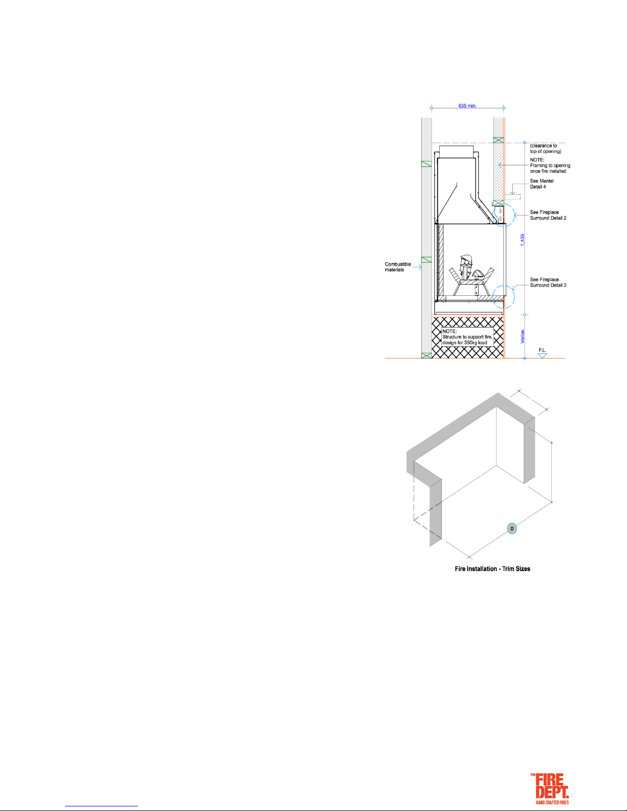
If the appliance is to sit on a plinth, ensure it is capable of
supporting a 350kg load.
There is no clearance requirement for the base of the appliance.
It may safely sit directly upon combustible (eg. timber)
and non-combustible (eg. concrete) materials.
Step 3: Install appliance into cavity
Before installation, confirm all minimum clearances
from the outside surfaces of the appliance to the
surrounding enclosure are no closer than 25mm from
combustible materials and 5mm from non-combustible
materials.
The exception to these minimum clearances is the base, the
front surround and lintel panels of the appliance. The base can
safely sit directly upon combustible (e.g. timber) and
non-combustible (e.g. concrete) materials and the front surround
and lintel panels can be placed hard against non-combustible materials
Please refer to the appropriate appliance specifications for all correct
clearance requirements.
• If a gas supply pipe has already been run to the cavity, ensure 1000mm of 3/8 soft copper tube is available
at the lower centre of the cavity, as this is where the copper tube with the gas supply enters the appliance.
• If an electrical supply cable has already been run to the cavity (must be a minimum of 1.0mm 4 core cable),
ensure that the cable reaches the centre of the cavity, as this is where it will enter the appliance.
• In order to access the fixing slots in the base of the appliance, and the gas and electrical connections, it is
necessary to first remove the exposed burner and base firebox lining.
Page 4
Version: March 2019 4
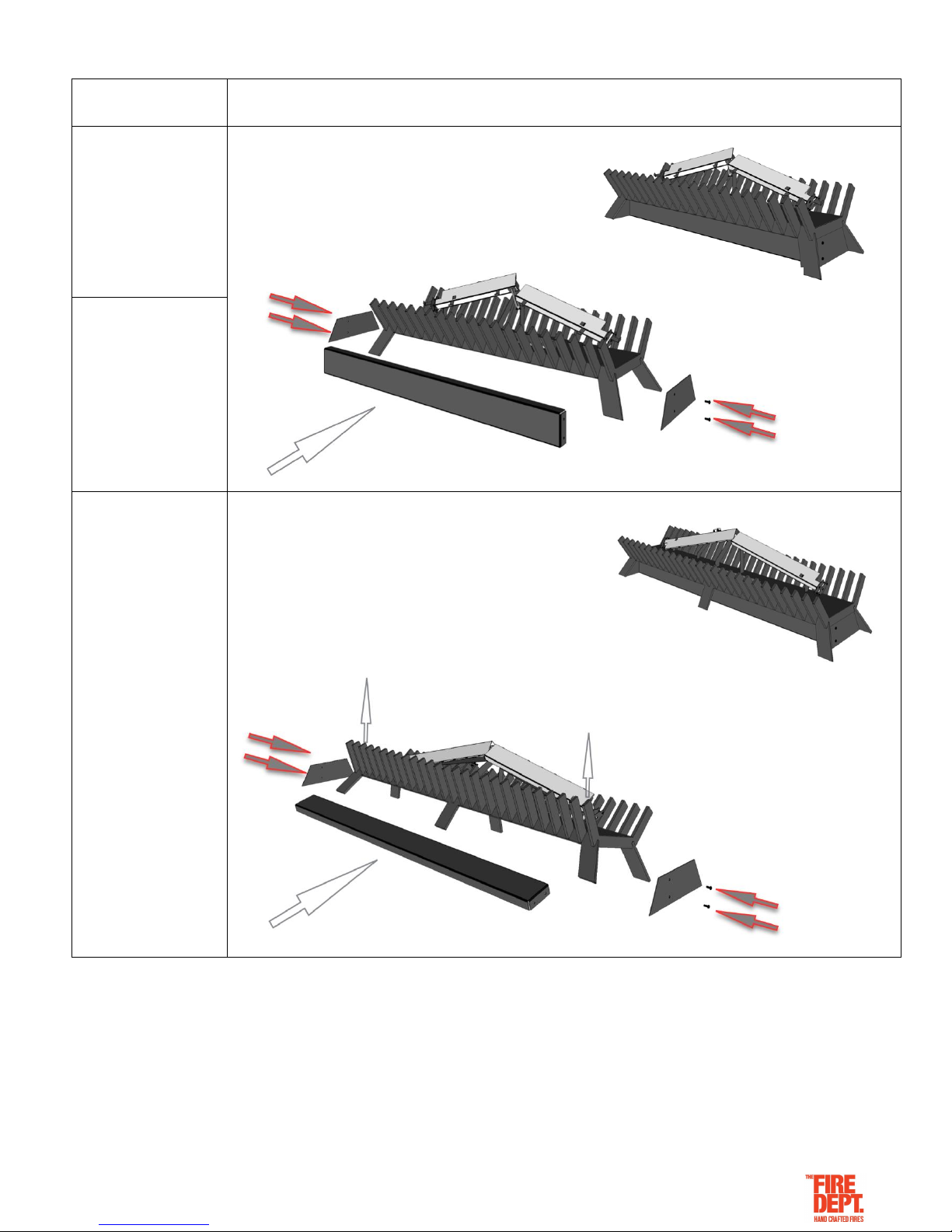
Exposed Burner Removal Process
LPG / Natural Gas
GD8 EB Cover Panels
GD8 EB 1200
Input 55-65 MJ/h
One gas injector on the
front burner tube and two
gas injectors on each of
the two rear burner tubes.
.
GD8 EB 1400
Input 55-65 MJ/h
One gas injector on the
front burner tube and two
gas injectors on each of
the two rear burner tubes
GD8 EB 1600
Input 65-70 MJ/h
One gas injector on the
front burner tube and two
gas injectors on each of
the two rear burner tubes
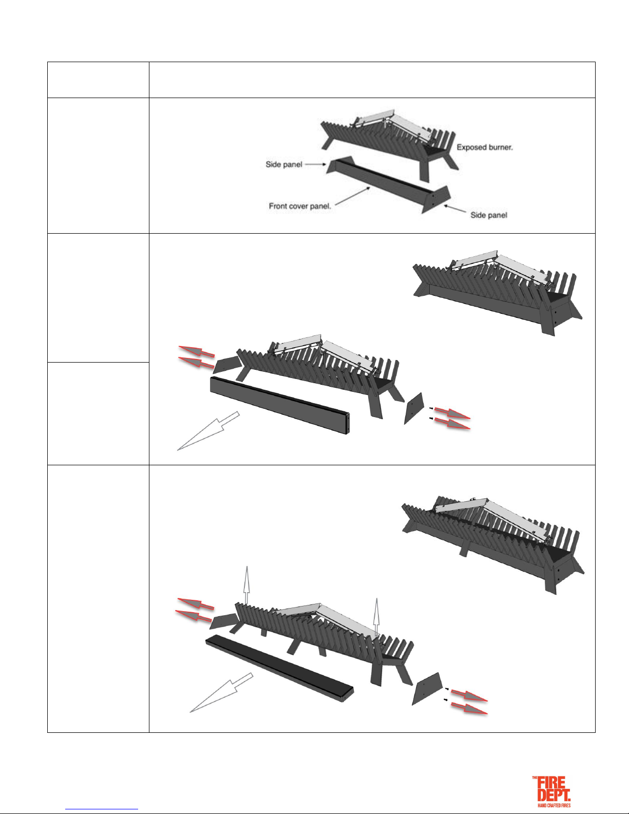
Remove the side panels (2 x screws) at each end of the
exposed burner.
Remove the front cover panel from under the exposed burner.
Remove the side panels (2 x screws) at each end of the
exposed burner.
Remove the front cover panel from under the exposed burner.
Note: It will be necessary to lift the exposed burner up (at the
front) to allow the front cover panel to clear under the supporting
leg.
Page 5
Version: March 2019 5
Exposed Burner Installation Process
LPG / Natural Gas
GD8 EB 1200
Input 55-65 MJ/h
One gas injector on the
front burner tube and two
gas injectors on each of
the two rear burner tubes.
GD8 EB 1400
Input 55-65 MJ/h
One gas injector on the
front burner tube and two
gas injectors on each of
the two rear burner tubes.
GD8 EB 1600
Input 65-70 MJ/h
One gas injector on the
front burner tube and two
gas injectors on each of
the two rear burner tubes
Fit the front cover under the exposed burner.
Replace the side panels (2 x screws) at each end of the
exposed burner.
Fit the front cover panel under the exposed burner.
Replace the side panels (2 x screws) at each of the exposed
burner.
Note: It will be necessary to lift the exposed burner up (at the
front) to allow the front cover panel to clear under the supporting
leg.
Page 6

Version: March 2019 6
Firebox Lining Removal Process
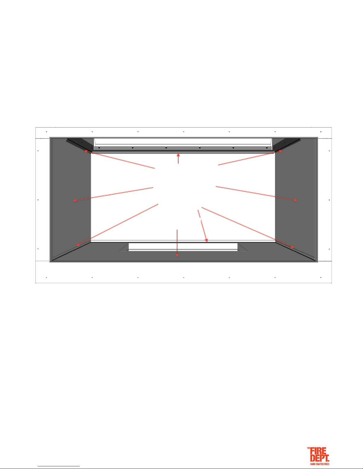
In order to install the GD8 Exposed Burner, the base firebox lining must be removed to gain access to the
base fixing brackets.
NOTE: in some circumstances (eg. the need to reduce overall weight so the appliance can be lifted up
stairs), it may be necessary to remove (then replace) all the firebox lining.
……………………….
The GD8 has four fire box lining options: Fire bricks, Steel, Dark tile & Client-supplied.
Particular care should be taken when removing and replacing the chosen Fire lining into the appliance.
Failure to place the firebox lining correctly may result in the appliance performing inefficiently.
Fire Brick lining:
Herringbone - Hand cut fire bricks, 230mm x 25mm x 50mm.
Finish - Honed surface with grey grout.
Repair grout. To grout all joints and fill all shrink back cracks
during appliance installation.
Steel lining:
Mild steel – 2mm.
Size – Cut and folded to suit appliance.
Finish – Matt black paint.
Dark tile lining:
Black slate – 9mm.
Size – 600mm x 600mm cut to suit.
Finish – Dark slate.
Client-supplied lining: Requirements
Non-combustible and heat-resistant.
Size – maximum thickness 50mm
Size – Minimum height for tiles 600mm
All measurements must be confirmed on site.
Finish – Robust and self-supporting.
Example of a client -suppled fire box lining
Page 7
Version: March 2019 7
This GD8 EB appliance is supplied with the chosen firebox lining or ready for the client-supplied firebox lining.
Note: Take care when removing the top fixing bracket. The top of the firebox lining will fall forward with the
bracket removed.
1. Remove the exposed burner by following the ‘Exposed Burner Removal Process’ in this guide.
2. Remove the top three lining fixing brackets. 5mm cap screws.
3. Allow the top of the lining to fall forward.
4. Carefully lift the lining up and out of the base channel.
5. Place the lining in a safe place.
6. Remove the base lining by carefully lifting the lining from the cavity at base from under the exposed burner.
7. To refit the lining simply reverse the removal process.
8. Install the exposed burner by following the ‘Exposed Burner Installation Process’ in this guide.
Lining fixing brackets
Lining to sides & back
Base channel
Lining to base
Page 8
Version: March 2019 8
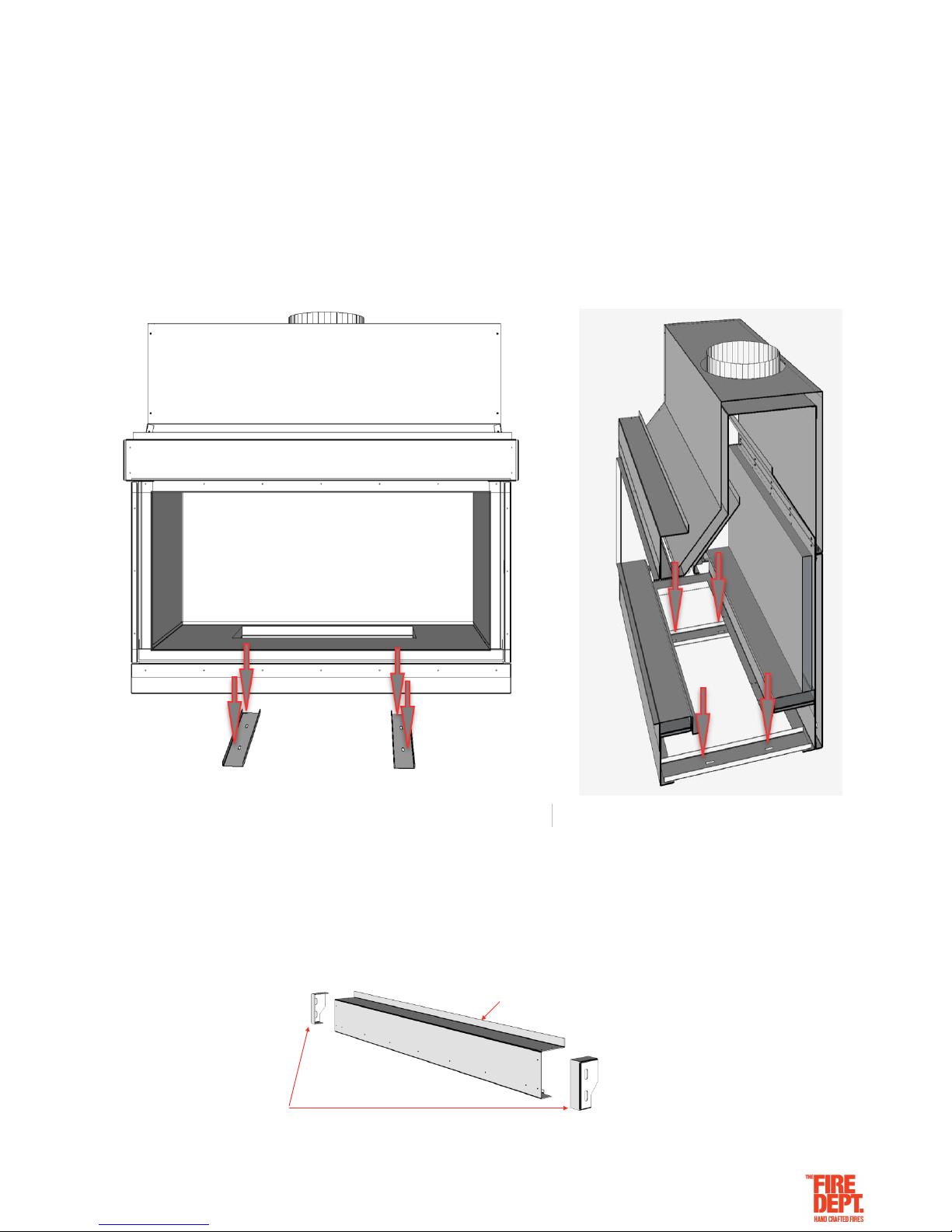
Once the base firebox lining has been removed, slide the appliance into position and ensure that it complies
with the minimum clearances required (25mm for combustibles, 5mm for non-combustibles) to the fire box
inner panels and 5mm surrounding enclosure. The exception to these minimum clearances is the base and
the outer 2mm steel lintel panel of the fire, the base can safely sit directly upon combustible (e.g. timber) and
non-combustible (e.g. concrete) materials. Ensure the framing is capable of supporting a 350kg load.
In order to provide maximum positioning flexibility, the base of the appliance has two fixing brackets with two
30mm long slots in each.
The two fixing brackets will clamp the appliance into position. Locate the fixing brackets and mark out and
drill fixing holes through the 30mm slots in the fixing brackets. Ensure holes are drilled in the centre of the
slots to allow maximum positioning flexibility. Clear out any debris from drilling.
Ensure the appliance is level and pack up corners to suit where necessary. Fix bolts/screws into floor. Check
and ensure unit is level.
Once the appliance is fixed into position the outer 2mm steel lintel panel can be bolt / screw fixed to the
cavity.
In order to provide maximum positioning flexibility, the outer 2mm steel lintel panel has two side fixing
brackets with two 30mm long slots in each.
Outer 2mm steel lintel panel
Side fixing brackets
Page 9
Version: March 2019 9
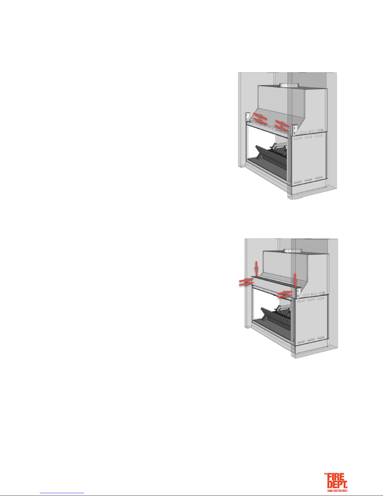
The two side fixing brackets will hold the outer 2mm steel lintel panel in position. Locate the fixing brackets
(see correct specifications or general assembly drawings) and mark out and drill fixing holes through the
30mm slots in the Side fixing brackets. Ensure holes are drilled in the centre of the slots to allow maximum
positioning flexibility. Clear out any debris from drilling.
Ensure the Side fixing brackets are level. Fix bolts/screws to the
side fixing brackets to each side of the cavity.
The outer 2mm steel lintel panel will fit snugly over and fix to the
side fixing brackets.
Replace the base firebox lining.
Replace the front panel and the exposed burner by following the ‘Exposed Burner Installation Process’ in
this guide.
Page 10
Version: March 2019 10
Step 4: Install flue and connect to appliance
Flue installation must meet the requirements of AS/NZS 5601.1:2013 and comply with all local council
requirements and be installed and certified by a suitably qualified person.
Refer to appropriate ‘The Fire Dept’ product specifications for specific minimum requirements. Only follow
the ‘Wall cowl assembly details’ (below) if the flue is to be terminated through a wall.
A 25mm clearance from combustible materials, 75mm clearance from wiring and plastic pipes and a
minimum of 5mm from non-combustible materials is required when installing a flue system for any appliance
supplied by ‘The Fire Dept.’.
The flue installation requires a restriction free cavity from the top of the firebox (flue spigot) to the outside
atmosphere.
Air flow must be unobstructed from the firebox to the inner flue and from the heat shield to outer casing
allowing air to circulate from the firebox to the flue casings to the atmosphere.
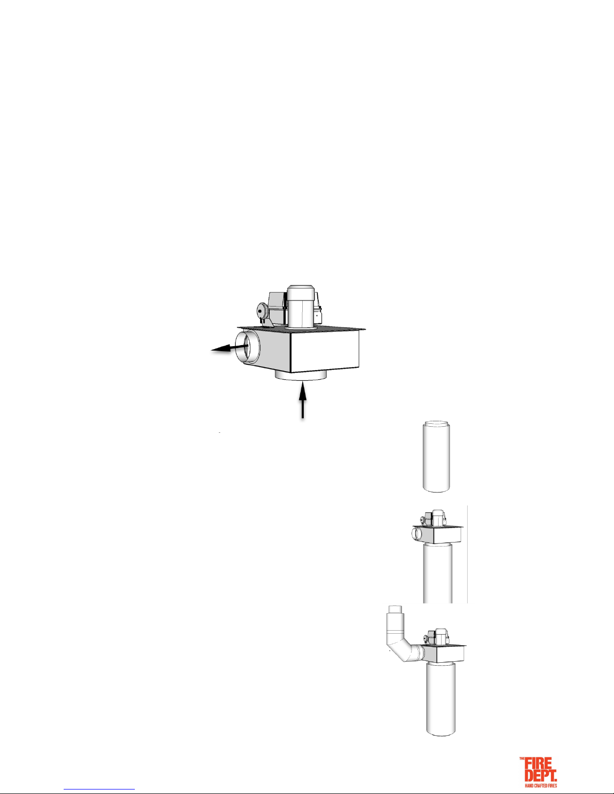
In-Line Fan assembly details
Step 1:
Step 1:
Connect the flue and outer casing to the firebox
1. Make sure the In-line fan has adequate access for future maintenance.
2. Run the flue from the appliance to the location of the In-line fan.
3. Run the outer casing from the appliance to finish 50mm shorter than the flue.
Step 2:
Connect the in-line fan to the flue and outer casing
1. Fit the casing slip over the outer casing.
2. Fit the flue over the inlet spigot to the In-line fan.
3. Fix the flue to the inlet spigot at the in-line fan.
Step 3
Complete the flue installation
1. Finish the casing with a 50mm gap to the in-line fan.
2. Complete the flue installation .Refer to appropriate’ product specification for
fixing details and specific minimum requirements.
Page 11
Version: March 2019 11
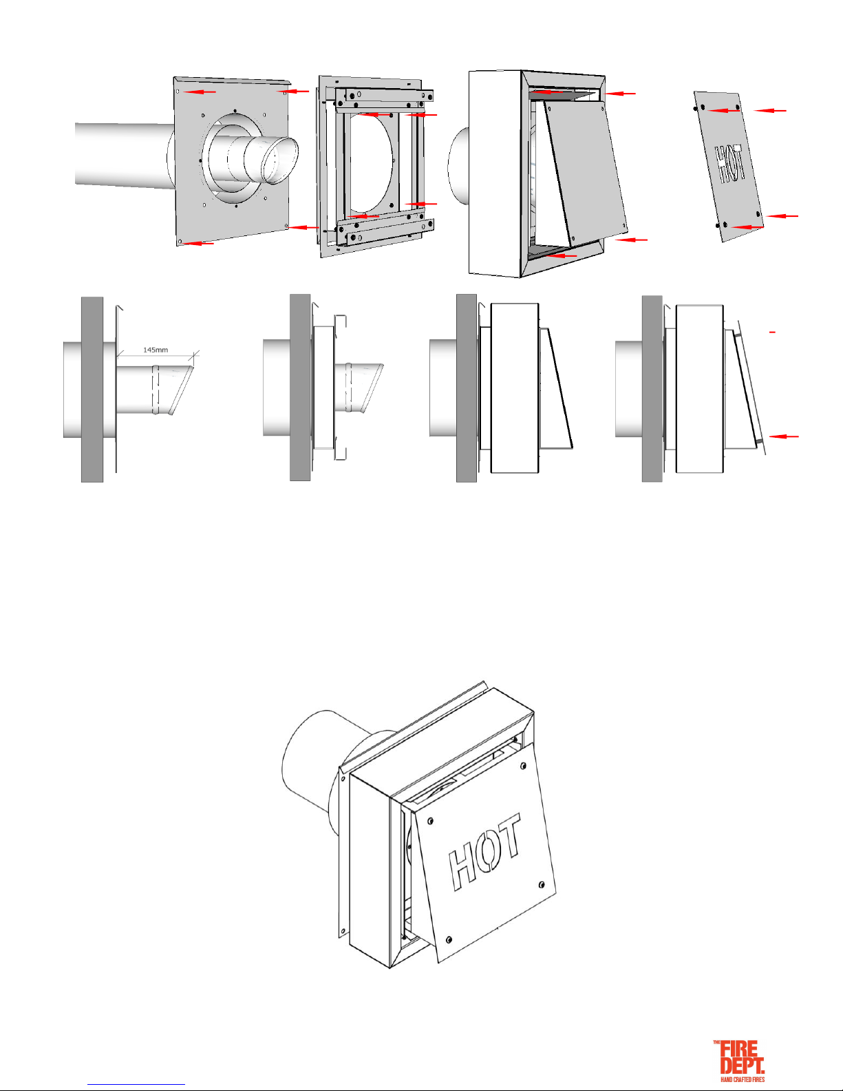
Wall cowl assembly details
Step 1:
Fix back panel to wall
1. Back panel must be flashed in
accordance with NZBC.
2. Outer flue casing to finish flush
with front of back panel.
3. Flue to finish 145mm out from
back panel.
Step 2:
Fix cowl support to back panel
1. Cowl support is fixed to back
panel with 4 x 5mm cap screws
2. Seal between cowl support.
and back panel with heat proof
sealer.
Step 3:
Fix cowl to cowl support
1. Cowl is fixed to back panel
with 4 x 5mm cap screws
2. The outer casing spigot
(attached to the cowl) will slide
into the outer flue casing.
Step 4:
Fix HOT panel to the cowl.
1. Hot panel is fixed to back
panel with 4 x 5mm cap
screws
Page 12
Version: March 2019 12
Step 5: Connect and test electrical supply
All electrical connections must meet the requirements of AS/NZS 3000 standards and be installed
and certified by a suitably qualified person.
•
In order to access the electricals, it is necessary to first remove the front cover panel. Follow the front cover
removal process on the ‘Exposed Burner Removal Process’ of this guide.
•
If the exposed burner needs to be removed. Follow the exposed burner removal process in the ‘Exposed
Burner Removal Process’ of this guide.
Note: The exposed burner can be lifted and supported at a height to give extra working room if required.
•
With the front panel removed the electrical connections between the appliance and the switch can be seen,
use 4 core (minimum 1mm) cable.
Following these connection details, using the 4 core cable that has been run at site, connect the switch to the
appliance.
•
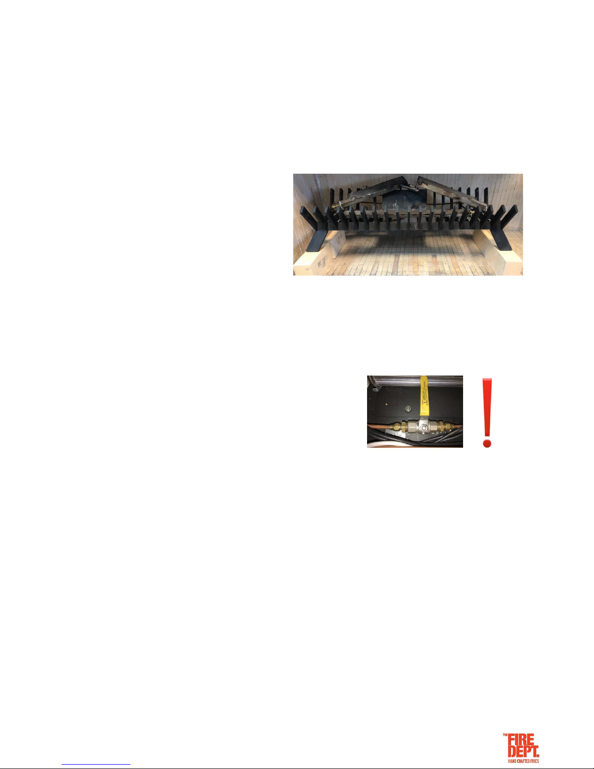
IMPORTANT: Before testing, ensure the gas valve is turned off.
Test electrical functions by switching the bottom High/Low switch to LOW, then switch the appliance ON
using the top On/ Off switch.
• After approximately five seconds, the pilot will spark. Because the gas supply is turned off, the pilot will
spark for approximately five seconds then automatically switch off.
• NOTE: GD8 models have both LOW and HIGH settings.
• Switch to HIGH setting. Ensure that a red light appears on the electrical connections block.
• Switch the appliance off. Electrical testing is complete.
• Replace the front panel and the exposed burner by following the ‘Exposed Burner Installation Process’ in
this guide.
Page 13

Version: March 2019 13
Page 14
Version: March 2019 14
Step 6: Connect gas supply and commission
• Gas installation, connection and commissioning must meet the requirements of AS/NZS 5601.1:2013
and be installed and certified by a suitably qualified person.
• In order to access the gas supply and testing area, it is necessary to first remove the front cover panel.
Follow the front cover removal process on the ‘Exposed Burner Removal Process’ of this guide.
•
If the exposed burner needs to be removed. Follow the exposed burner removal process in the ‘Exposed
Burner Removal Process’ of this guide.
Note: The exposed burner can be lifted and supported at a height to give extra working room if required.
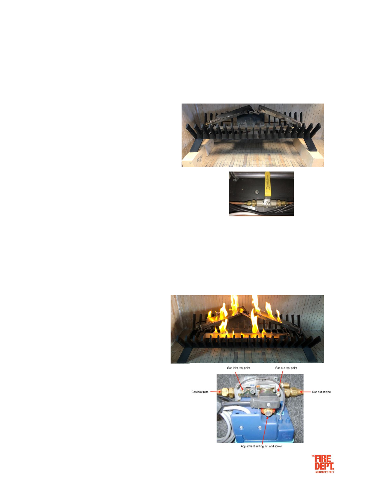
• Connect 3/8 soft copper pipe to main valve.
In the unlikely event that the rating plate is not attached, Do Not commission the appliance and contact ‘The
Fire Dept.’ immediately.
• Replace the exposed burner (if removed) by following the ‘Exposed Burner Installation Process’ in this
guide.
• Switch the appliance on.
• Note: due to lack of firebed, it may be necessary to manually light burners.
• Leak test all joints.
• Test/adjust high first and then the low pressures
against rating plate specifications.
• Switch the appliance off.
• Lay firebed in accordance with instructions in Step 7 of
this guide.
• Send gas certificate to the appropriate person.
Page 15
Version: March 2019 15
Step 7: Lay the firebed
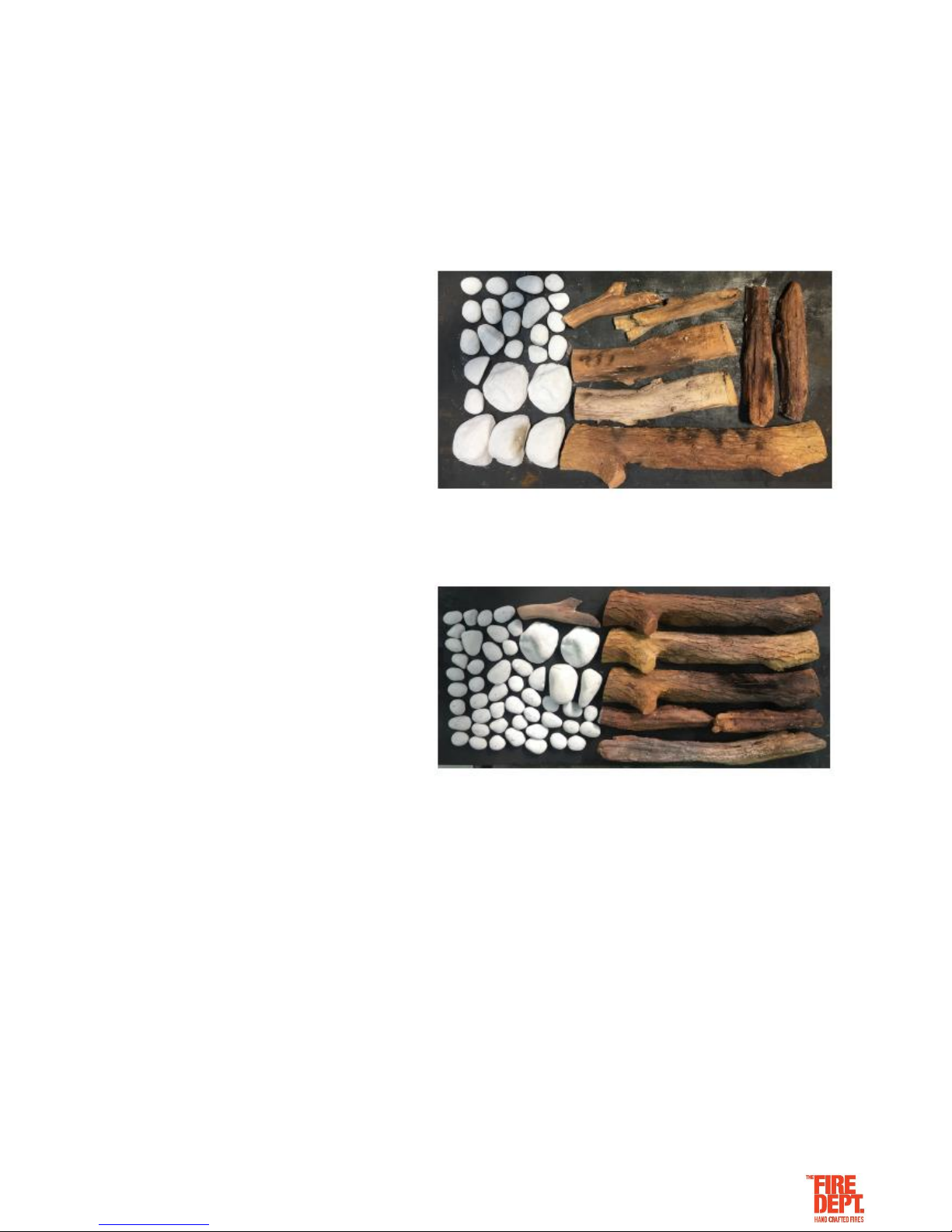
The GD8 Exposed Burner has two firebed mediums: white rocks and logs.
• Particular care should be taken when placing the firebed mediums into the burners. Failure to place the
medium correctly may result in the appliance performing inefficiently.
• Open the firebed cardboard box and identify firebox mediums.
GD8 EB 1200 & 1400 has two firebed mediums:
Logs – large and small
White rocks – large and small
GD8 EB 1600 has two firebed mediums:
Logs – large and small
White rocks – large and small
Page 16
Version: March 2019 16
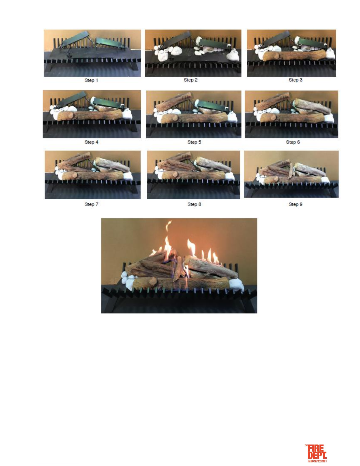
How to lay the Firebed – GD8 EB 1200 and 1400
• Switch the appliance on at ‘HIGH’ setting to check how flame looks. The flame will take 10-20 seconds to
light fully.
• IMPORTANT: the flame effect should look natural and non-uniform, running the entire length of the burner.
• Common flame effect issues are:
o Flame burning under logs.
o Missing flames along length of burner.
• Both these issues can be resolved by switching the appliance off and slightly repositioning rocks and logs at
the problem areas.
• Repeat this switching on/off and repositioning until a natural and non-uniform flame effect is achieved.
• Once a natural and non-uniform flame effect is achieved, switch the appliance to ‘LOW’ setting and ensure
the flame effect, although smaller, still looks good.
• Switch the appliance off.
Page 17
Version: March 2019 17
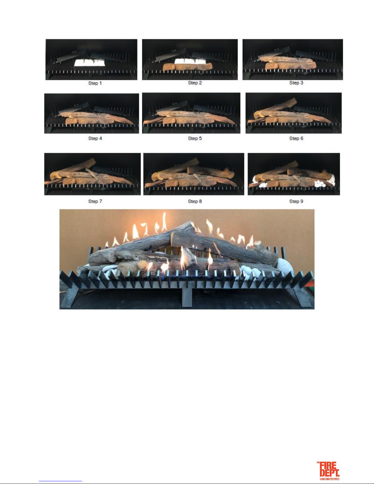
How to lay the Firebed – GD8 EB 1600
• Switch the appliance on at ‘HIGH’ setting to check how flame looks. The flame will take 10-20 seconds to
light fully.
• IMPORTANT: the flame effect should look natural and non-uniform, running the entire length of the burner.
• Common flame effect issues are:
o Flame burning under logs.
o Missing flames along length of burner.
• Both these issues can be resolved by switching the appliance off and slightly repositioning rocks and logs at
the problem areas.
• Repeat this switching on/off and repositioning until a natural and non-uniform flame effect is achieved.
• Once a natural and non-uniform flame effect is achieved, switch the appliance to ‘LOW’ setting and ensure
the flame effect, although smaller, still looks good.
• Switch the appliance off.
Page 18

Version: March 2019 18
Step 8: Show owner how to operate appliance
• Following the GD8 Exposed Burner Operating Instructions on the next page, show the owner how to switch
the appliance on and off, and how to switch between high and low settings.
• If the owner is not available, leave this manual by the appliance.
NOTES:
Page 19
Version: March 2019 19
GD8 EB OPERATING INSTRUCTIONS
This GD8 appliance has been designed to be simple to use. It is controlled by a wall switch, which must be
installed by a qualified electrician.
To start appliance:
• Press the on/off switch to the ON position.
• Press the high/low switch to the HIGH position.
• The electronic solenoid pack will start to click.
• Gas will then be released and ignited at the pilot valve.
• The safety sensor will allow the main burner pipe to ignite and flames will appear. The whole process
will take between 10-20 seconds.
• Once the flame appears, it can be turned down to the low setting by pressing the high/low switch to LOW.
To shut down appliance:
• Press the on/off switch to the OFF position.
• The gas will automatically be shut off to the pilot and the burner. The flame will then extinguish.
………………………………………
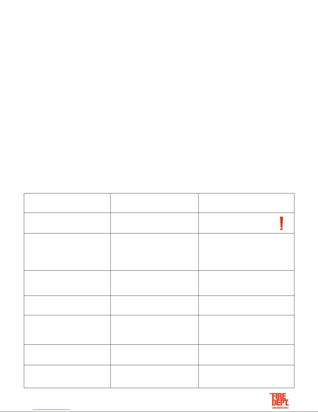
TROUBLESHOOTING
Problem
Probable Cause
Action
Appliance shuts down after continuous
running.
Low oxygen supply to the appliance
1. Do not attempt to restart the fire.
2. Open all doors and windows.
3. Call gas-fitter.
Appliance doesn't start
1. No gas supply
2. No power supply
3. Low or poor pilot flame
4. Signal from flame rectifier interrupted
5. Signal to sparker electrode interrupted
6. Incorrect sparker electrode gap
1. Check gas supply
2. Check power supply
3. Check flame size and pressure
4. Check flame rectifier and wire to sit pack
5. Check sparker gap and wire to sit pack
6. Check sparker electrode gap is 3mm
Appliance shuts down
1. Low gas supply
2. Low or poor pilot flame
3. Signal to flame rectifier interrupted
1. Check gas supply
2. Check flame size and pilot flame pressure
3. Check flame rectifier and wire to sit pack
Flame in not running the full length of the
burner
The firebed is not aligned to the burner
Re-lay the firebed to the specific model
specifications detailed earlier in this guide
Flame is yellow and sooty
1. Primary aeration ports have a
blockage (LPG models only)
2. The firebed is not aligned to the burner
1. Check primary aeration ports for blockage
and clear if required (LPG models only)
2. Re-lay the firebed to the specific model
specifications detailed earlier in this guide
No flame at the pilot
Primary aeration ports have a blockage
Check primary aeration ports for blockage and
clear if required
(For models with an in-line flue fan)
If the in-line fan is running and the
appliance doesn’t start or shuts down
Low air flow supply from the appliance
1. See ‘Appliance doesn't start’ above.
2. See ‘Appliance shuts down’ above.
3. Call gas-fitter.
Page 20

Version: March 2019 20
PRODUCT WARRANTY
IMPORTANT: Evidence of original purchase is required for warranty service.
WARRANTOR: ‘The Fire Dept.’ (Landscape Elements Ltd)
85 Newton Road
Mount Maunganui
PO Box 10275, Bayfair, Mount Maunganui
ELEMENT OF WARRANTY
‘The Fire Dept.’ warrants to the original retail owner for the duration of this warranty, it’s fireboxes, gas burner tray, lighters,
(herein after referred to as the Product) to be free from defects in materials and craftsmanship with only the limitations or
exclusions set out below.
WARRANTY
This warranty will be deemed invalid if the Product is;
(A) Installed by someone other than an authorised Fire Dept agent.
(B) Not operated appropriately or “over-fired” in a manner resulting in the firebox operating excessively hot.
(C) Not serviced and maintained by a certified gas fitter every 12 months.
(D) Damaged by accident, neglect or misuse,
(E) Repaired by someone other than an authorised Fire Dept repair agent for a defect or malfunction covered by this
warranty.
(F) Modified, altered or used as part of any conversion kits, subassemblies, or any configurations not sold by ‘The Fire
Dept.’.
(G) The product contains fire bricks and has not been subjected to the recommended first start-up and run-in procedure.
(H) Used in conjunction with any equipment or parts or as part of a system not manufactured or supplied by ‘The Fire Dept.’.
(I) External powder-coating within 200m of the high tide mark and not lightly washed with warm soapy water every three
months.
Indoor appliances (Gas & Wood)
‘The Fire Dept.’. warrants the mild steel firebox, galvanised steel outer skin and RHS Duragal steel support frame against
defective materials and workmanship which would render it unfit for normal domestic use, from the date of purchase by the
original consumer, for a period of 5 (five) years. Beyond normal heat-induced staining, tarnishing and mild warping , if a
firebox, outer skin or support frame defect occurs, contact ‘The Fire Dept.’ and the defect will be repaired or replaced at our
discretion with all costs covered.
‘The Fire Dept.’ warrants the SIT Pack (Gas regulator and controller) against defective materials and workmanship which
would render it unfit for normal domestic use, from the date of purchase by the original consumer, for a period of 2 (two)
years.
Components including fire medium, fans, tiles, glass and glass trim are warranted for a period of 2 (two) years from the date
of original purchase, against defective materials and workmanship.
Outdoor appliances (Gas & Wood)
‘The Fire Dept.’ warrants the Mild Steel firebox, galvanised steel outer skin and RHS Duragal Steel support frame against
defective materials and workmanship which would render it unfit for normal domestic use, from the date of purchase by the
original consumer, for a period of 2 (two) years. Beyond normal heat-induced staining, tarnishing and mild warping, If a
firebox, outer skin or support frame defect occurs, contact ‘The Fire Dept.’ and the defect will be repaired or replaced at our
discretion with all costs covered.
‘The Fire Dept.’ warrants the SIT Pack (Gas regulator and controller) against defective materials and workmanship which
would render it unfit for normal domestic use, from the date of purchase by the original consumer, for a period of 2 (two)
years.
Components including fire medium, fans, tiles, glass and glass trim are warranted for a period of 2 (two) years from the date
of original purchase for domestic use, against defective materials and workmanship.
STATEMENT OF REMEDY
In the event that the Product does not conform to this warranty at any time while this warranty is in effect, the Warrantor, at
its discretion, will repair the defect or replace the part and return it to you without charge for parts or service. This warranty
does not provide for reimbursement or payment of incidental or consequential damages.
This warranty does not in any way affect your rights under the Consumers Guarantee Act (New Zealand).
 Loading...