


WB505R / WB505L
Wireless DECT7 Base Station
Manual
7340 SW Durham Road, Portland, OR 97224 USA
Phone: 800-527-0555, 503-684-6647, Fax 503-620-2943
www.firecom.com • e-mail: service@firecom.com


Table of Contents
Overview .................................................................................................................. 1
Contents in Box........................................................................................................ 2
Accessories (not included) ....................................................................................... 2
Features ................................................................................................................... 3
Wireless DECT7 Communications .......................................................................... 3
Mounting ................................................................................................................. 4
Antennas .................................................................................................................. 5
Duck Antenna ......................................................................................................... 5
Accessory Antennas ............................................................................................... 6
Power....................................................................................................................... 7
Option 1: DC Jack Power ........................................................................................ 7
Option 2: Digital Intercom Power .......................................................................... 8
Modular Plug Installation ........................................................................................ 9
LED Indicators ........................................................................................................ 10
Top ....................................................................................................................... 10
Front ..................................................................................................................... 10
Use with a Digital Intercom – WB505R.................................................................. 11
Setting up Digital Intercom Mode (WB505R default) .......................................... 11
Digital Intercom Radio Transmit .......................................................................... 11
Intercom Only ...................................................................................................... 11
Base Station connected to a Firecom Digital Intercom ........................................ 12
Use with a Legacy Intercom – WB505L ................................................................. 13
Setting up Legacy Intercom Mode (WB505L default) .......................................... 13
Intercom Connections .......................................................................................... 13
Base Station connected to a Firecom Legacy Intercom ....................................... 14
Use in a Comhub .................................................................................................... 15
Setting up Comhub mode, and the number of channels ..................................... 15
Pairing .................................................................................................................... 16
Full-Duplex Pairing ............................................................................................... 16
Broadcast Only Pairing ......................................................................................... 16
PC Programming .................................................................................................... 17
Locating the USB Port .......................................................................................... 17
Installation of the Sonetics Configurator Software .............................................. 17
Troubleshooting .................................................................................................... 18
Service Contact: ................................................................................................... 18
WB505R / WB505L Specifications ......................................................................... 19
DECT Specifications .............................................................................................. 20
Important Safety Information ............................................................................... 21
Firecom Standard Limited Warranty ..................................................................... 26

Overview
Firecom Wireless Base Stations support the RF connections of Firecom wireless
communication systems. The Base Station supports full duplex, conference call
like digital communication for up to five Firecom DECT7 Wireless Headsets.
Radio PTT capable Headsets can be set up to transmit on a mobile radio via a
Firecom Digital Intercom. For installations which need a greater number of
users, Broadcast mode supports up to 100 users. Broadcast users share
connections to take turns talking with the group.
Firecom DECT7 wireless, operating on the 1.9GHz band provides secure,
interference-free, full-duplex communication. Wireless Headsets have a
wideband connection of up to 7kHz. This gives a line-of-sight range of up to
1,600 feet. With internal and external antennas, the Wireless Base Station
configures itself for the best reception. Multiple Wireless Base Stations and
Intercoms can be combined to support up to 60 users in a single audio
network. USB programming allows complete customization.
1 | P a g e
Contents in Box
Base Station
1 ea x Wireless Base Station
Antenna
1 ea x Duck Antenna
1 ea x Duck Antenna Mount
1 ea x Wire Tie
Manual and Reference
1 ea x Manual
1 ea x FCC/IC certification sheet
1 ea x ComCare sheet
Power
1 ea x DC Power Cable
1 ea x in-line Fuse Holder & Fuse
Accessories
1 ea x RJ45 Intercom Interface Kit
1 ea x RJ12 Intercom Interface Kit
8 ea x RJ12 Connectors
1 ea x Mounting Feet Kit
1 ea x USB Cable
Accessories (not included)
Magnet Mount Remote Antenna
RJ12 Flat Cable
Permanent Antenna
Auxiliary Input Radio Interface - Connect to virtually any radio
and many other devices
Worldwide Power Adaptor
2 | P a g e

Features
USB Programmable
Using its USB port, a Base Station can be configured using a Windows PC.
Features may be customized and saved. Refer to the Sonetics Headset Software
for details.
Wireless DECT7 Communications
The Base Station features wireless DECT7, enabling conference call-like full
duplex communication. The Firecom wireless DECT7 Base Station will connect
with Firecom Wireless Headsets and Belt Packs. DECT7 networks have up to
1600ft line-of-sight range in Region 1 (US) and up to 800 meters in Region 2
(EU). DECT7 ensures interference free, digitally encrypted communications for
all parties.
Backwards Compatibility
The Firecom Wireless Base is backwards compatible with the Firecom first
generation wireless DECT and DECT6 headsets, with minimal loss in
functionality.
Wide Band Audio
The Wireless DECT7 communications are transmitted in a high definition wide
band audio format. This gives greater clarity of voice, and allows for integration
with voice activated control systems. It can be switched to narrow band audio
when necessary.
Dual Antenna Design
The Base Station has internal and external antennas for diversity switching to
lock onto the best signal. This allows the installer to place the Wireless Base
Station and antenna in different locations for system optimization in custom
installations.
Multi-Channel System
The Wireless Base Station can be configured for multiple channels. These can
be remotely selected by paired Wireless Headsets.
Broadcast Only Mode
The Headset may be paired into a listen only mode of operation, reducing
power consumption considerably. This also allows many more headsets to be
connected to a Wireless Base Station simultaneously. Pressing the Radio PTT
button allows the headset to momentarily talk on any available slot. A tone will
let the user know when they can talk. After talking, there will be a slight delay
when other users cannot be heard.
3 | P a g e

Mounting
The Wireless Base Station is designed to mount on a variety of surfaces. The
unit includes internal and external antennas. Consideration must be given to
antenna location to optimize performance.
WARNING: Do not locate the Wireless Base Station within 4” of any
metal.
If the Wireless Base Station must be located in a non-optimal location, use an
external accessory remote antenna.
Option 1: Window Glue Mount
1. Remove duck antenna.
2. Clean the location where the wireless base will be installed.
3. Remove the protective backing from the 3M double-sided tape on the
bottom of the wireless base.
4. Press firmly to the window.
Option 2: Fixed mount with Feet
1. Remove one of the screws on the bottom of the Base Station.
2. Place a mounting foot, and attach it using a replacement screw.
3. Repeat for the other three screws.
4. Mount the Wireless Base Station using the mounting feet.
5. Position antenna and use antenna mount to secure it. Alternatively, use a
remote antenna.
Option 3: Desk
1. Place on Desk.
2. Orient the external duck antenna vertically or use a remote antenna.
4 | P a g e

Antennas
An external antenna can provide a performance increase in some locations, and
affords greater installation flexibility.
To optimize performance:
1. Position the antenna at least 12 inches from any other antenna, metal,
electrical power, radio equipment, or obstructions.
2. Choose a location in the center of the vehicle’s roof (if mounting
outside).
WARNING: For FCC and other Radio Frequency regulatory compliance,
use only Sonetics approved wireless antennas.
Duck Antenna
Always position the Duck antenna at 90 degrees from the internal antenna. The
internal antenna is shown below.
The duck antenna needs to be supported when used in a vehicle or any
environment when the Wireless Base Station may be subjected to vibration.
5 | P a g e

Accessory Antennas
Sonetics has accessory antennas for temporary and permanent installation on
the exterior of a vehicle or building. To ensure the best system performance,
external antennas must not be mounted inside metal enclosures.
Magnet Mount Antenna
This antenna is designed for non-permanent installations on metallic surfaces.
1. Temporarily mark the center of the vehicle’s roof or trunk. Centering the
antenna on a flat metal area will improve ground plane and increase range.
2. Clean the marked area with rubbing alcohol or other non-corrosive cleaner
to prepare the surface. Let it dry completely.
3. Cut a round piece of felt the same size as the bottom of the magnet mount
and place it on your center mark. Set the magnetic antenna on top of the
felt to protect to the vehicle’s paint from scratches. Use of a felt patch will
slightly reduce the strength of the magnet. Make sure the coaxial cable is
pointed toward where it will enter the vehicle.
4. Open the hood or the trunk. Route the cable through a body panel gap to
get to the base station location.
5. Connect the cable to the antenna connector on your Wireless Base Station.
Do not over tighten the antenna! Finger tight plus 1/8th a turn is sufficient.
Permanent Mount Antenna
This antenna is designed for permanent installation. Have a qualified radio
installer perform the installation.
6 | P a g e

Power
The Wireless Base Station can be powered from the DC Jack or directly from a
Digital intercom. The unit will automatically power on when power is applied.
WARNING: Use only one power option to prevent ground loops.
Option 1: DC Jack Power
Wall Adapter Charging
Only charge the base station using the supplied 12VDC regulated wall adapter.
WARNING: Use only approved wall adaptors.
Vehicle Charging
Connect the BLACK wire with WHITE dashes to +12V and the BLACK wire to
chassis ground. Install the fuse no further than 18" from the battery.
WARNING: Only replace fuse with the same type, 0.5A AGU.
WARNING: Voltages exceeding the headset charging specification will
damage the headset.
7 | P a g e

Option 2: Digital Intercom Power
1. Connect one RJ-45 modular plug as shown above. Both the Power and
Ground will be connected from the Digital Intercom to the Wireless Base
Station. Any input will power the Wireless Base Station.
2. Adjust the fuse of the Digital Intercom to include the current draw from
the Wireless Base Station.
3. Additional connections to the Digital Intercom using a 6 pin wire, and RJ-12
connectors.
8 | P a g e

Modular Plug Installation
1. Using the cutter blade on the crimping tool (A), cut the flat CA Cable so the
cut is clean and 90 degrees to the sides of the cable.
2. Insert one end of the CA Cable between the stripping blades (C) until the
end of the cable hits the stop (B).
3. Squeeze the handles of the crimping tool together until the tool bottoms
out.
4. While holding the handles together, pull the cable out of the tool.
5. The stripped insulation should expose approximately 3/16” of wire.
6. Push a RJ Modular Plug into the plug holder on the crimping tool (D) until
the release tab on the plug locks into position.
7. Holding the cable so that the printed side (or smooth side) of the cable is
toward the release-tab on the plug, push the cable into the plug as far as it
will go.
ALWAYS make sure the printed side (or smooth side) of
the cable is facing the release-tab on the RJ Modular Plug.
8. Squeeze the tool handles COMPLETELY together. You may feel the crimper
finish punching the contacts through the insulation on the wires.
9. Let the handles spring open.
10. Push down on the release-tab on the RJ Modular Plug and remove the RJ
Modular Plug from the crimping tool.
11. Inspect the plug to ensure that the cable is held securely in place.
9 | P a g e

LED Indicators
Top
Power Indicator
Lights when unit has power and is turned on.
Link Indicators
There is one light per wireless position. These indicate the connection status of
the wireless devices paired onto the Wireless Base.
Off – No wireless device is paired to this position
Slow Flashing – Pairing Mode Active
Fast Flash – Device paired, no connection.
Solid Light – Device paired and connected
Front
Radio Transmit (Red LEDs)
Indicates the radio transmit activity for each output.
Mode/Channel Indicators (Green LEDs)
These are used to set up the Base Station for Comhub, Intercom, or Legacy
Intercom functionality.
10 | P a g e

Use with a Digital Intercom – WB505R
(5000 Series Digital Intercoms)
The Wireless Base Station is designed to integrate into a Firecom Intercom
system. This lets the user operate two-way-radios with a Wireless Headset.
When used in Intercom mode, the Base Station must be connected to a
Firecom Intercom for Headsets to communicate with one another. Only one
channel is available in Digital Intercom Mode.
Setting up Digital Intercom Mode (WB505R default)
1. Unplug the Base Station, then plug it back in while holding the Pairing
buttons for positions 1 and 2 until the green channel indicator LEDs for
positions 1 and 2 light up (about 5 seconds).
2. The Base Station is now in Digital Intercom mode.
3. Unplug the Base Station, then plug it back in. The Base Station is now
ready to use.
Digital Intercom Radio Transmit
Some models of Wireless Headsets have radio transmit capability built in.
Headsets can receive and transmit via the built in PTT button. The Wireless
Base Station must be connected to a Firecom intercom that is connected to a
two-way-radio. Consult your Intercom manual for instructions on how to
connect them.
1. Make sure your Headset is a radio transmit model and that it is configured
to transmit radio over DECT. Consult your Headset manual for
instructions.
2. Pair the Headset to the desired position on the Base Station.
3. Connect the port for that position to a Firecom Intercom using a flat cable.
4. Repeat for other positions needing Radio transmit capability.
5. Test and verify each position. The Red LED next to the connected port on
your base station will light when the Headset is radio transmitting.
Intercom Only
For Intercom only functionality, the Wireless Base can be connected to the
Firecom Intercom using the intercom port. All Headsets will communicate over
the intercom using only position 6. No radio push to talk function will be
available.
1. Pair the Headset to the desired position on the Base Station.
2. If radio transmit capability is needed for a headset, follow the instructions
above under "Digital Intercom Radio Transmit".
11 | P a g e

Base Station connected to a Firecom Digital Intercom
Examples:
Stand Alone, No Radio Interface
All positions communicate locally via the Base Station
only. With no connection to a Digital Intercom, the
headsets will only be able to communicate with other
headsets connected to the Wireless Base Station.
Intercom Only Connected to Digital Intercom
All positions communicate over the Intercom only. No
radio transmit is available.
Mixed mode, Radio PTT with Intercom only Connected to Digital
Intercom
Positions 1 & 2 have radio transmit capability. All
positions have intercom communications through the
intercom port. Positions 3, 4, and 5 do not have radio
transmit capability (any position connected via its
own cable will have radio transmit capability).
12 | P a g e

Use with a Legacy Intercom – WB505L
(30XXR, 110, and 210 Intercoms)
The Wireless Base Station is designed to integrate into older Legacy Firecom
Intercom systems. This lets the user operate two-way-radios with a Wireless
Headset. When used in Legacy Intercom mode, the Wireless Base Station must
have Ports 1 and 6 connected to the Firecom Intercom. This allows Intercom
Only headsets to hear the communications of a headset utilizing radio transmit.
Only one channel is available in Legacy Intercom Mode.
Setting up Legacy Intercom Mode (WB505L default)
1. Unplug the Base Station, then plug it back in while holding the Pairing
buttons for positions 2 and 3 until the green channel indicator LEDs for
positions 2 and 3 light up (about 5 seconds).
2. The Base Station is now in Legacy Intercom mode.
3. Unplug the Base Station, then plug it back in. The Base Station is now ready
to use. In this mode, the position a Headset is paired to does not impact
its operation.
Intercom Connections
1. In this mode port 6 must be connected to a Firecom Intercom using the
supplied flat cable.
2. Pair the Headset(s) to the Base Station. For Radio Transmit operation,
make sure your Headset is a radio transmit model and that it is configured
to transmit radio over DECT. Consult your Headset manual for
instructions.
If Radio Transmit operation is required, connect port 1 to the Firecom
intercom using the correct type flat cable. The Firecom intercom must be
connected to a two-way-radio.
Operation
All non-radio transmit audio is through Port 6 of the Base Station. When a
Radio Transmit headset initiates a transmission by activating its PTT button, its
audio is switched to Port 1 along with the PTT signal.
13 | P a g e

Base Station connected to a Firecom Legacy Intercom
Examples:
Intercom Only Connected to Digital Intercom
The Intercom port only is connected. All paired
devices will only transmit over the Intercom. No
intercom radio transmit is available. Make sure all
headsets are set to intercom only modes.
Radio PTT Connected to Digital Intercom
Positions 1 through 5 are radio transmit capable.
PTT signal for all paired devices operate through the
position 1 connection. The Intercom continues to
operate through the Intercom Port.
14 | P a g e

Use in a Comhub
In addition to being used in an installed system, your Base Station can be used
in a portable Comhub. Up to 5 channels are available through the Wireless
Base Station when used in this configuration.
Setting up Comhub mode, and the number of channels
To enter configuration mode:
1. Unplug the Base Station, then plug it back in while holding the position 3
pairing button.
2. Hold the pairing button until the green channel indicator LED turns on (see
"Mode/Channel Indicators" on page 10).
3. The Base Station is now in Comhub mode.
4. To set the number of available channels, press the pair button
corresponding to the number of channels desired (button 2 = 2 channels,
etc). The current number of channels is shown with a green LED on the
associated Mode/Channel Indicator (e.g. Port 5 = 5 channels).
5. To exit configuration mode, unplug your base station from power, then
plug it back in. The Base Station is now ready to use.
15 | P a g e
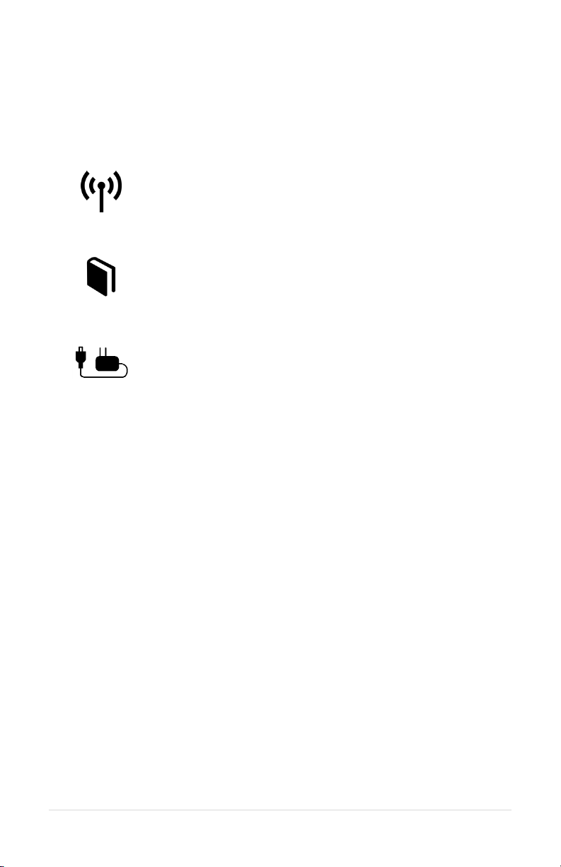
Pairing
Pairing creates a connection between the Wireless Base Station and the
headset. This is only required once. After pairing, Headsets will connect
automatically.
Full-Duplex Pairing
1. Press and hold the desired pairing button until its link indicator begins to
flash slowly. Any previous pairing to that position will be forgotten.
2. Place the Firecom headset into pairing mode by pressing the right PTT
button and the power button until you hear "base station registering".
3. The Base Station will automatically connect, showing a solid link led.
4. If the pairing was unsuccessful, repeat all steps above.
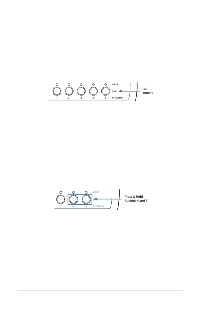
Broadcast Only Pairing
Broadcast Only allows up to 100 devices to be paired to the Wireless Base
Station. One active full duplex device pairing must exist for the Broadcast
channel to be opened. Broadcast users never have Radio Transmit capability.
Example: Position 1 has a Full Duplex headset pairing. Positions 2-4 are
available for devices to share. Position 5 broadcasts back to the group.
1. Press and hold Buttons 4 & 5 until 4 & 5 link LEDs begin to flash slowly.
2. Place the wireless device you wish to link into pairing mode.
3. The wireless base will automatically connect, showing a solid link LED on
position 5 and the device will show that it is connected (refer to the
Firecom device manual).
4. If the pairing was unsuccessful, repeat steps 1-3.
5. To pair additional devices, repeat steps 1-4 with another device.
Because Broadcast Only Headsets share communication positions, there can be
slight delays in communication. To talk, the Push-To-Talk button must be held
until a position opens. After a Broadcast call is made, there will be a pause in
which incoming communications cannot be heard
16 | P a g e

To exit Broadcast Only mode:
Press and hold 4 or 5 until the link LED flashes slowly indicating pairing mode.
PC Programming
The Wireless Base Station has a USB port located near the Antenna Jack. Using
the Sonetics Configurator software, you can adjust additional features using a
Windows PC. Refer to the program for additional information.
Locating the USB Port
Installation of the Sonetics Configurator Software
1. Go to www.SoneticsCorp.com/software.
2. Download and Install the software for the wireless base station.
3. Use a mini-USB cable to connect the Wireless Base Station to a Windows
PC. The Base Station will power up.
4. Open the Sonetics Configuration Software.
5. Follow the directions given by the Sonetics Configuration Software.
17 | P a g e

Troubleshooting
Note: If you are experiencing symptoms not covered here, or are having
difficulty troubleshooting, call us or visit our website. We’re here to help.
Service Contact:
Phone: 800-527-0555, 503-684-6647, service@firecom.com
No indication of power to the base station
1. Make sure that the Wireless Base Station has the correct power
connection, and that it is plugged in completely.
No audio communication and/or PTT from or to the base.
1. Make sure the Wireless Headset(s) are on, connected, and are using the
same channel (if base station is set for multiple channels).
2. Ensure that the modular communication cable is correctly connected
between the Wireless Base Station and Intercom.
3. Check the modular communication cable between the Wireless Base
Station and Intercom for continuity.
4. Ensure correct polarity of the modular plug on both ends of the modular
cable.
Poor quality audio, low or distorted audio.
1. Check the intercom volume. Set the volume level as high as possible on the
Intercom without causing distorted audio on the Headset, and then adjust
the volume control on the Headset for comfortable listening.
2. Poor quality audio can be caused by a defective Headset. Confirm
operation with a Headset known to be functioning properly.
3. Ensure your Wireless Base Station and Intercom are configured correctly.
Audible interference from portable and mobile radios.
1. Care should be taken to install cables away from radio and antenna cabling
to prevent RF interference.
Poor coverage range.
1. Check the Wireless Base Station and external antenna locations. They
should not be installed inside metal enclosures or closer than 4 inches to a
metal object or surface.
2. Poor range can also be caused by a defective Headset. Check operation
with a known, properly functioning Headset.
3. If the problem persists, contact Firecom Service for additional help.
18 | P a g e

WB505R / WB505L Specifications
Physical
Length: 5.70in / 145mm
Width: 2.72in / 69mm (not including external antenna)
Height: 1.22in / 31mm
Weight: 5.6oz / 158g
Power
Voltage Input: 5 VDC to 16 VDC
Maximum Current Input: 400mA @ 5V, 150mA @ 12V
Environmental
IP-Rating: IP-20
Operating temperature: -40°F to 176°F / -40°C to 70°C
Storage temperature: -40°F to 185°F / -40°C to 85°C
FCC
FCC ID: V9N950325700V1
FCC Part 15: All Models
Industry Canada
IC UPN: 7895A-950325700
MIL SPEC
Humidity: MIL-STD 810F and 810G
Temperature Shock: MIL-STD 810F and 810G
SAE / NFPA 1901
Vibration: J1455 Sec. 4.9
Conducted Immunity: J1113-11
Electrostatic Discharge: J1113-13
Radiated Emissions: CISPR 25
Radiated Immunity: ISO 11452-2
ISO
Conducted Transients: 7637-2
Quality Management System Control: ISO 9001:2008
19 | P a g e

DECT Specifications
Common DECT Specifications
Carrier Spacing: 1.724 MHz
Time Slots: 2 x 12 (up and down stream)
Channel Allocation: Dynamic
Encryption: DECT Standard Cipher with 35-bit initialization vector
Audio Bandwidth: 300 Hz to 3.4 kHz, Narrow Band, G.726 compression
50 Hz to 7 kHz, Wide Band, G.722 compression
Region 1 Specific Specifications
Authorized for use in: Canada, USA
Frequency Bandwidth: 1919.808 MHz to 1930.176 MHz
Number of Carriers: 5
Total Time Slots: 60 in G.726(narrow band) / 30 in G.722(wide band)
Average Output Power: 4 mW
Maximum Output Power: 100 mW
Range (line of sight): 1600 feet maximum
20 | P a g e

Important Safety Information
CAUTION! Follow all warnings and instructions marked on the product or
contained in the owner’s manual.
When using this product, always follow basic safety precautions to reduce the
risk of fire, electric shock and injury to persons, including the following:
Do not use the wireless system to report a gas leak in the vicinity of the
leak.
Use only the power adapters, and power cords indicated in the manual. If
more than one type of power adapter is included in the product, the
manual specifies which adapter should be used for each component. Be
sure to use the proper adapter for each product component.
Do not place the power cord where it creates a trip hazard or where it
could become chafed and create a fire or electrical hazard.
Do not subject the unit to high temperatures or leave it in direct sunlight
for an extended period of time.
SAVE THESE INSTRUCTIONS!
Warning for Sensitive Electronic Devices
This equipment and any radio-based electronics can potentially cause
electromagnetic interference with other equipment and can be interfered with
by other equipment. This also applies with DECT based equipment. Due to the
very low transmission power associated with DECT, the chance for interference
is small. However some specific precautions must be taken into account for
sensitive electronic equipment e.g. sensitive laboratory equipment, medical
instruments or medical implants to avoid incidental influence of equipment
operated in straight nearness to sensitive electronic equipment. You are
therefore advised not to place the DECT equipment or its antenna in close
proximity to sensitive equipment by maintaining a 20cm minimum distance
between the sensitive equipment even in standby mode. Please also consider
referencing the documentation provided by us and the manufacturer of
sensitive electronic items guiding its proper usage.
General Communication Privacy Notice
Although this equipment may contain specific protocols that enhance security
and privacy of communication, privacy of communication may not be ensured
when using this equipment.
21 | P a g e

Notice:
Modification not expressly approved of by Sonetics Corporation could void the
users authority to legally operate the equipment and will nullify warranty. This
includes the use on non-approved antennas or 3rd party amplifiers with the
radio base station.
This section applies to radio frequency equipment bearing an
I.C. Equipment ID Number.
Under Industry Canada regulations, this radio transmitter may only operate
using an antenna of a type and maximum (or lesser) gain approved for the
transmitter by Industry Canada. To reduce potential radio interference to other
users, the antenna type and its gain should be so chosen that the equivalent
isotropically radiated power (e.i.r.p.) is not more than that necessary for
successful communication.
This radio transmitter IC: 7895A-950325700 has been approved by Industry
Canada to operate with the antenna types listed below with the maximum
permissible gain and required antenna impedance for
each antenna type indicated. Antenna types not included in this list, having a
gain greater than the maximum gain indicated for that type, are strictly
prohibited for use with this device.
Approved Antennas for use with this device:
WB505R / WB505L Wireless Base Station Antenna
Sonetics Part Number: 521-0014-00 (3dBi)
Magnet Vehicle Mount
Sonetics Part Number: 114-0139-00 (4.4dBi) (Sold Separately)
Permanent Mount Antenna
Sonetics Part Number: 114-0138-00 (4.4dBi) (Sold Separately)
22 | P a g e

This section applies to radio frequency
equipment bearing an I.C. equipment
ID number.
This device complies with Industry
Canada license-exempt RSS
standard(s).
Operation is subject to the following
two conditions:
(1) this device may not cause
interference, and
(2) this device must accept any
interference, including
interference that may cause
undesired operation of the device.
Ce dispositif est conforme à la norme
CNR d'Industrie Canada applicable aux
appareils radio exempts de licence.
Son fonctionnement est sujet aux
deux conditions suivantes:
(1) le dispositif ne doit pas produire
de brouillage préjudiciable, et
(2) ce dispositif doit accepter tout
brouillage reçu, y compris un
brouillage susceptible de provoquer
un fonctionnement indésirable.
Caution
This base station, other base stations
or approved base station antenna
meant to be used in conjunction with
this equipment must not be used in
close proximity to the body. Keep a
minimum distance of greater than 20
CM to the human body. This device
and antenna must not be co-located
in conjunction with any other
equipment antenna or transmitter.
Attention:
Déclaration d'exposition aux
radiations:
Cet équipement est conforme aux
limites d'exposition aux
rayonnements IC établies pour un
environnement non contrôlé. Cet
équipement doit être installé et utilisé
avec un minimum de 20 cm de
distance entre la source de
rayonnement et votre corps.
Canada SAR Information:
This device contains a radio transmitter. This device has been shown to be
capable of compliance for localized specific absorption rate for uncontrolled
environmental / general public exposure limits specified in RSS-102,
ANSI/IEEC95.1-2002 and have been tested in accordance with the
measurement procedures specified in IEE 1528-2003.
23 | P a g e

FCC Part 15 Information
This device complies with part 15 of the FCC rules. Operation is subject to the
following two conditions:
(1) This device may not cause harmful interference, and
(2) This device must accept any interference received, including interference
that may cause undesired operation.
Modifications not expressly approved by Sonetics Corporation could void the
user’s authority to operate the equipment.
FCC/IC RF Exposure Warning
This product complies with FCC radiation exposure limits set forth for an
uncontrolled environment.
To comply with FCC RF exposure guidelines the base station and any
antennas must be installed and operated 20cm (8 inches) or more between
the product and all persons body (excluding extremities of hands, wrists and
feet). Note: All necessary accessories are included in the package; any
additional or optional accessories are not required for compliance with the
guidelines.) Use of other accessories might not comply with FCC or IC RF
exposure guidelines.
This product may not be collocated or operated in conjunction with any
other antenna or transmitter.
This device has been tested and meets the FCC RF exposure guidelines.
24 | P a g e

FCC Authorized Antenna Information:
Under FCC regulations, this radio transmitter may only operate using an
antenna of a type and maximum (or lesser) gain approved for the transmitter
by FCC. To reduce potential radio interference to other users, the antenna type
and its gain should be so chosen that the equivalent isotropically radiated
power (e.i.r.p.) is not more than that necessary for successful communication.
This radio transmitter has been approved by Industry FCC to operate with the
antenna types listed below with the maximum permissible gain and required
antenna impedance for each antenna type indicated.
Antenna types not included in this list, having a gain greater than the maximum
gain indicated for that type, are strictly prohibited for use with this device.
Approved Antennas for use with this device:
SON150 Wireless Base Station Antenna Sonetics P/N: 521-0014-00 (3dBi)
Magnet Vehicle Mount Sonetics P/N: 114-0139-00 (5.5dBi) (Sold Separately)
Permanent Mount Antenna, Sonetics P/N: 114-0138-00 (5.5dBi) (Sold
Separately)
25 | P a g e

Firecom Standard Limited Warranty
Firecom, a division of Sonetics Corporation, (“Firecom”) warrants to the original purchaser of its
products that products will be free from defects in materials and workmanship under normal and
proper use for the period of two years from date of purchase.
Firecom will repair or replace, at its option, any products showing factory defects during this
warranty period, subject to the following provisions and obligations:
1. This warranty applies only to a new product sold through authorized channels of distribution.
2. All work under warranty must be performed by Firecom.
3. All returned products must be shipped to our address, freight prepaid and Firecom will return
products to customer via ground freight. Any expedite fees or additional freight charges will
be charged to customer.
4. Any attempt to repair, service, or alter the product in any way voids this warranty.
5. This warranty does not apply in the event of accident, abuse, misuse, liquid contact, improper
installation, unauthorized repair, tampering, modification, fire, earthquake, or damage from
other external sources – including damage caused by user-replaceable parts.
6. This warranty does not apply: (a) to consumable parts such as batteries, ear seals, intercom
bags, cables, external power supplies, parts listed as accessories to a system, or other parts
designed to diminish in function over time unless a failure is due to a defect in materials or
workmanship; (b) to cosmetic damage or to defects caused by normal wear and tear or aging
of the product; (c) to damage caused by use with non-Firecom products; (d) to damage
caused by operating the product outside the permitted or intended uses or environments
described by Firecom; (e) to damage caused by service performed by anyone who is not a
representative of Firecom or an Firecom Authorized Service Provider; (f) to a product or part
that has been modified without the written permission of Firecom; (g) if any Firecom serial
number has been removed or defaced.
7. This warranty does not extend to any other equipment, apparatus, vehicle, aircraft, or
watercraft to which this product may be attached or connected.
THE FOREGOING IS YOUR SOLE REMEDY FOR FAILURE IN SERVICE OR DEFECTS. SONETICS
CORPORATION SHALL NOT BE LIABLE UNDER THIS OR ANY IMPLIED WARRANTY FOR INCIDENTAL
OR CONSEQUENTIAL DAMAGES, NOR FOR ANY INSTALLATION OR REMOVAL COSTS OR OTHER
SERVICE FEES. THIS WARRANTY IS IN LIEU OF ALL OTHER WARRANTIES, EXPRESS OR IMPLIED,
INCLUDING THE WARRANTY OF MERCHANTABILITY OR FITNESS OF USE, WHICH ARE HEREBY
EXCLUDED. TO THE EXTENT THAT THIS EXCLUSION IS NOT LEGALLY ENFORCEABLE, THE
DURATION OF SUCH IMPLIED WARRANTIES SHALL BE LIMITED TO TWO YEARS FROM DATE OF
PURCHASE. NO SUIT FOR BREACH OF EXPRESS OR IMPLIED WARRANTY MAY BE BROUGHT AFTER
TWO YEARS FROM DATE OF PURCHASE.
Subject to the terms and limitations of this Firecom Standard Limited Warranty, this warranty
covers any new covered product found to be defective within the applicable warranty period.
Firecom reserves the right to examine the alleged defective covered product to determine whether
this Firecom Standard Limited Warranty is applicable, and final determination of warranty coverage
lies solely with Firecom. If Firecom determines that warranty coverage applies, Firecom reserves
the right to either repair or replace a covered product or any part thereof, as determined by
Firecom in its sole discretion. If the product has been subjected to conditions which exclude
coverage under the warranty, customer will be so advised. Customer may then authorize paid
repair service or other disposition of the product. Notwithstanding any other provision of this
warranty, if you sell or otherwise transfer ownership of your covered product, this Firecom
Standard Limited Warranty shall automatically terminate.
26 | P a g e

Page intentionally left blank.
27 | P a g e


Firecom, a division of SONETICS CORPORATION
Copyright ©2015 Sonetics Corporation - All rights reserved.
The information in this document is subject to change without notice.
P/N: 600-0386-00 Rev. E
 Loading...