

Page 1
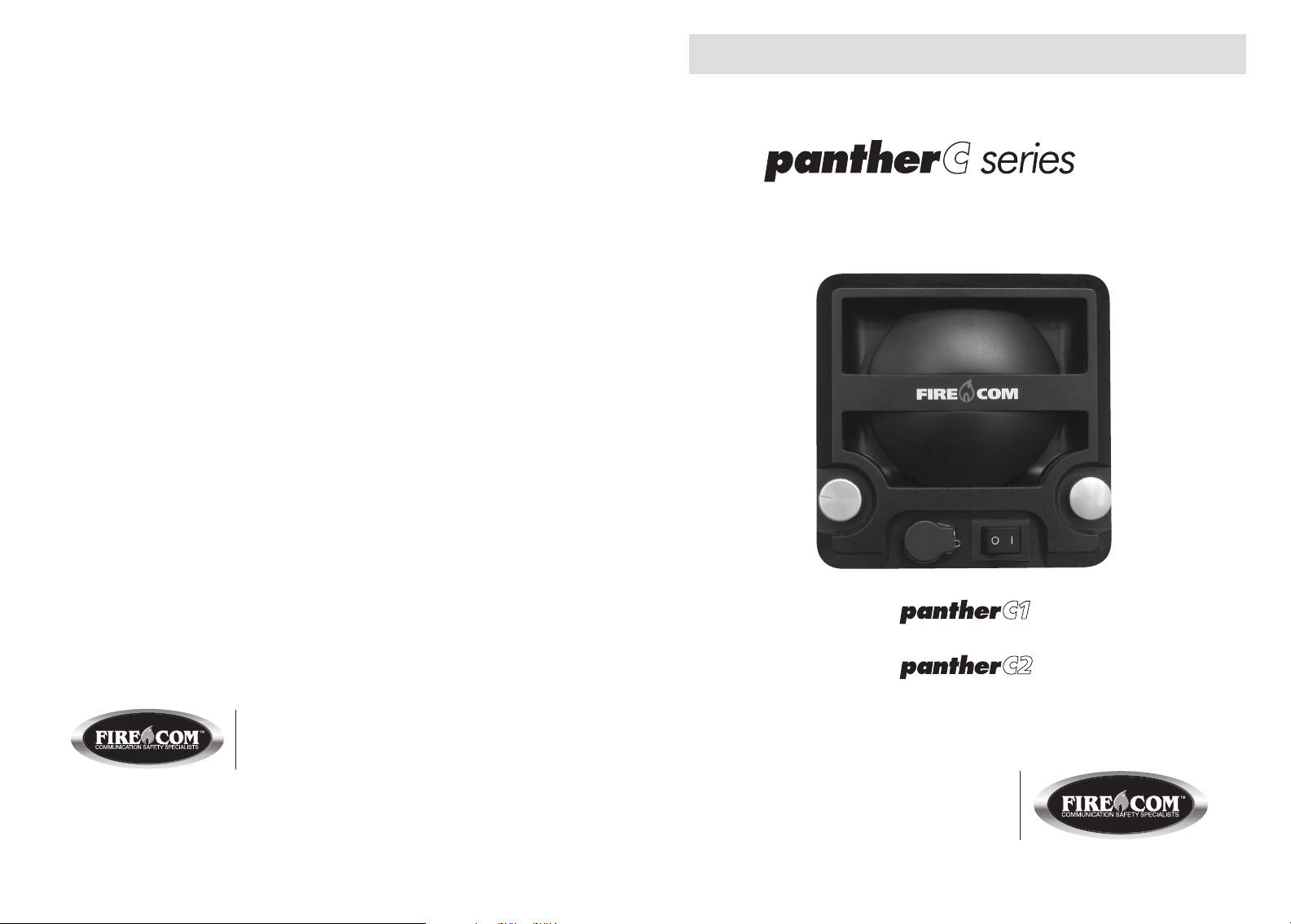
Intercom System Operation Manual
Base Unit Intercom
FIRECOM is a division of Sonetics Corporation
7340 SW Durham Road • Portland, Oregon 97224
800-527-0555 • 503-684-6647 • Fax: 503-620-2943
Email: [email protected] • www.firecom.com
Copyright © 2008 Sonetics Corporation - All rights reserved.
The information in this document is subject to change without notice.
No part of this document may be reproduced in any form without prior written consent of Sonetics Corporation.
This document is part number 600-0472-00 RevA. Printed in China.
Remote Unit Intercom
7340 SW Durham Road • Portland, OR 97224 USA
Phone: 503-684-6647 • 1-800-527-0555
Fax: 503-620-2943 • email: [email protected]
www.firecom.com
Page 2

TABLE OF CONTENTS
Overview . . . . . . . . . . . . . . . . . . . . . . . . . . . . . . . . . . . . . . . . . . . . . . . . . . . . 2
Features . . . . . . . . . . . . . . . . . . . . . . . . . . . . . . . . . . . . . . . . . . . . . . . . . . . . . 3
Intercom Models . . . . . . . . . . . . . . . . . . . . . . . . . . . . . . . . . . . . . . . . . . . . . . . 4
Installation . . . . . . . . . . . . . . . . . . . . . . . . . . . . . . . . . . . . . . . . . . . . . . . . . . 4-5
Wire Connections . . . . . . . . . . . . . . . . . . . . . . . . . . . . . . . . . . . . . . . . . . . . . . 6
System Wiring . . . . . . . . . . . . . . . . . . . . . . . . . . . . . . . . . . . . . . . . . . . . . . . 7-8
Operation . . . . . . . . . . . . . . . . . . . . . . . . . . . . . . . . . . . . . . . . . . . . . . . . . . . . 9
Troubleshooting . . . . . . . . . . . . . . . . . . . . . . . . . . . . . . . . . . . . . . . . . . . .10-11
Options and Accessories . . . . . . . . . . . . . . . . . . . . . . . . . . . . . . . . . . . . . . . . 12
Maintenance . . . . . . . . . . . . . . . . . . . . . . . . . . . . . . . . . . . . . . . . . . . . . . . . 13
Appendix A – Network Installation Tips . . . . . . . . . . . . . . . . . . . . . . . . . . . 13-16
Warranty . . . . . . . . . . . . . . . . . . . . . . . . . . . . . . . . . . . . . . . . . . . . . . . . . . . . 17
1
Page 3
OVERVIEW
FEATURES
The Firecom pantherC series is a digital intercom system designed for use in
rugged, physical conditions and challenging acoustic environments. The durable
construction, with recessed controls, is ideal for use on fire apparatus, emergency
vehicles or any other mobile command equipment. The pantherC series provides
high volume, clear digital audio communication. NFPA 1500 standards require
hearing protection for extreme noise environments over 98dB. Firecom headsets
should be added to the intercom system for additional hearing protection.
The digital, two-wire network system is designed to provide clear communication
for all personnel with minimal installation work. Multiple pantherC series units may
be installed in series to service a large network of stations without audio degradation.
The remote unit, typically installed at the ladder tip, includes a live microphone to
continuously transmit to base station units. Base station units include a Push-To-Talk
(PTT) button to transmit to other intercom positions. All units include a headset
jack. With the addition of headsets, all personnel have full two-way communication
capability, radio transmit, and receive (requires the analog interface unit), as well as
excellent hearing protection.
Radio transmit and receive can be added to the pantherC series with an analog
interface unit. The optional interface unit provides full radio communications with
either a Firecom “in-cab” intercom or with direct input from a two-way radio. The
pantherC1 base stations can keep personnel fully informed by monitoring radio
traffic. In addition, all positions on the pantherC series have radio transmit capability
by using a Firecom series 10 headset with red PTT button.
WARNING
Safety Information
Firecom’s pantherC series intercom speaker is loud enough to cause hearing damage. Use the
volume control provided on the intercom to reduce the speaker volume to a safe level for the
environment in which the intercom is being used or use Firecom headsets to reduce noise.
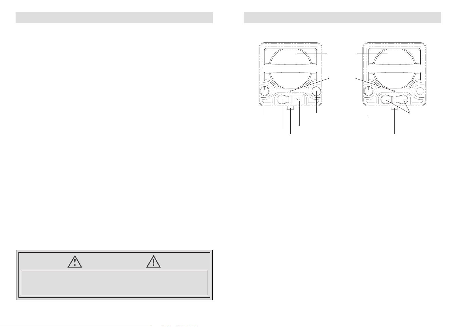
Volume
Control
Headset Jack
Base Station
pantherC1
Wire Connection
PTT button
(Push-To-Talk)
Power Switch
Speaker/Mic
Status Light
Remote Station
pantherC2
Volume
Control
Wire Connection
Headset
Jacks
Speaker
The speaker broadcasts audio when headsets are not used.
Status Light
The status light illuminates when a station is operating properly. An internal diagnostic
check is performed every time a unit is turned on.
Volume Control
The volume knob controls the audio level of the speaker. It will not turn the audio
completely off.
Microphone
The microphone receives audio. It is activated by the PTT button on base stations
and “live” on remote stations. The microphone is deactivated when ever a Firecom
10 series headset with a red PTT is plugged in.
Panel PTT Button
The PTT button activates the microphone on base stations.
Power Switch
The power switch (only on the base units) controls station power. It will not affect other
stations.
Headset Jacks
Use only Firecom 10 series headsets with red PTT buttons in the headset jacks for
hands-free, full-duplex communications. Additional radio or in-cab communications
are available. See “Options and Accessories” section in this manual.
Wire Connection
See “System Wiring” section in this manual.
32
Page 4
INTERCOM MODELS
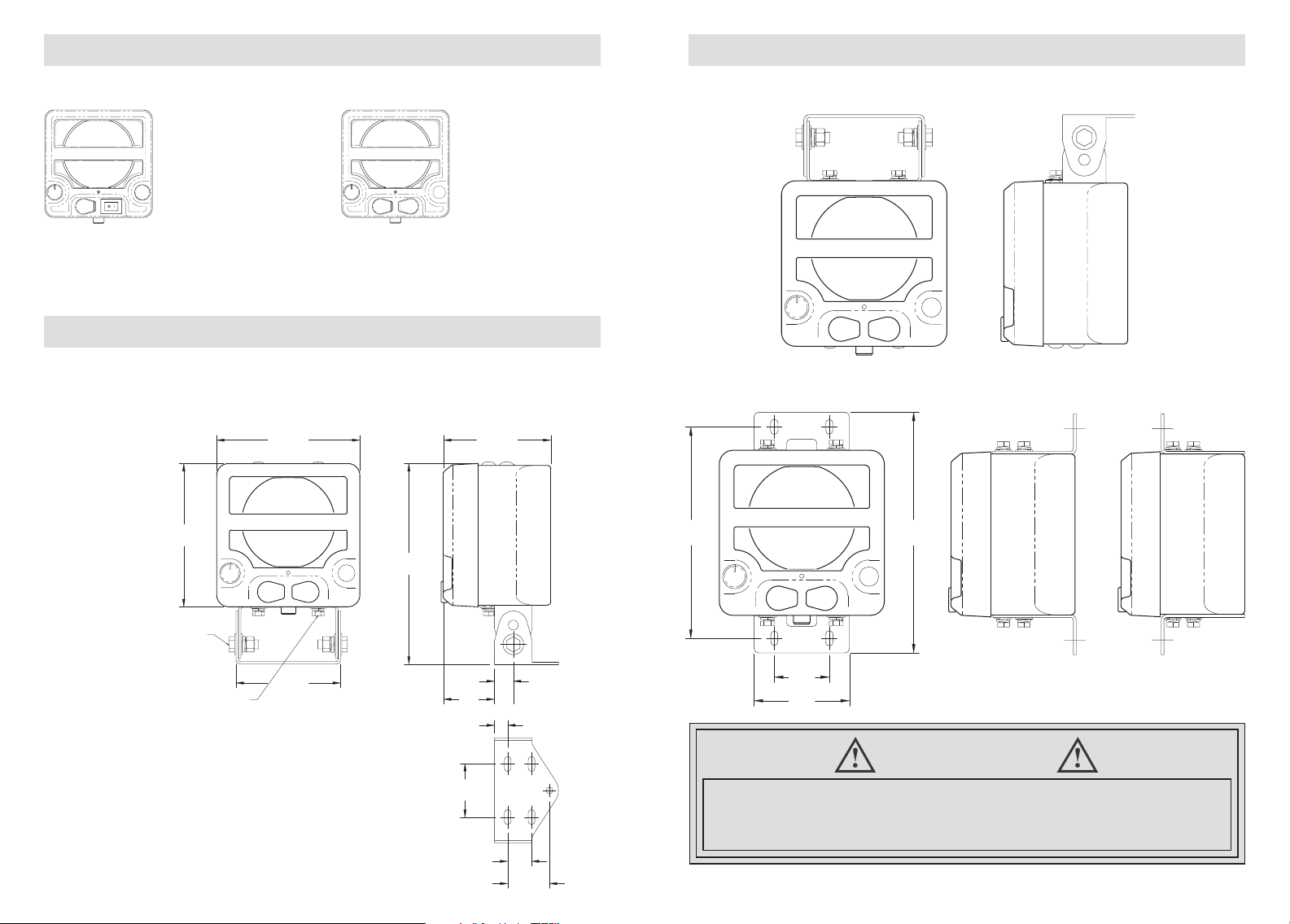
2.25
[57]
1.00
[25]
1.75
[44]
6.00 [152]
6.00
[152]
8.40
[213]
4.50 [114]
2.14
[54]
.79
[20]
4.38 [111]
.55
[14]
1/4 INCH MOUNTING HARDWARE
MAX. TORQUE 90 IN-LBS.
(4) PLACES
(PROVIDED)
3/8 INCH SWIVEL HARDWARE
MAX. TORQUE 220 IN-LBS.
(PROVIDED)
(2) PLACES
INSTALLATION
There are two pantherC series intercom models: base stations and remote stations.
Base Station
Base stations broadcast
sound via a speaker
when audio is provided
from another unit.
Depressing the PTT
button activates the
microphone and deactivates the speaker.
When a headset is used, hands-free fullduplex communication is available and the
speaker and microphone are disabled.
The speaker is activated and microphone
deactivated, only when other units are sending.
When a headset is used, hands- free fullduplex communication is available.
Remote Station
Remote stations have
“live” voice activated
microphones that will
always broadcast to
other stations when
sound is present.
INSTALLATION
Both an adjustable swivel style mounting bracket and two angle brackets are provided.
A flush mount bracket is also available (see Options and Accessories).
Mounting and Overall Dimensions (swivel mount bracket included)
Units: Inches
[Millimeters]
Optional Top Mounting
Optional Angle Bracket Mounting (included)
7.69
[195]
8.75
[222]
Mounting Hardware (included)
(4) 1/4 X 7/ 8 inch bolts
(8) flat washers
(4) lock washers
(4) nuts
4
2.00
[51]
3.46
[88]
WARNING
Safety Information
Do not install unit on a flat, horizontal surface. If installed improperly, wet weather
may cause water to pool in the speaker port, decreasing performance.
Unit must be installed at an angle of 45 degrees or more.
5
Page 5
WIRE CONNECTIONS
SYSTEM WIRING
Power
12 VDC (2.5 amps maximum)
A 5 amp fuse is required
Wire Size
Power:18 gauge min.
Network: 22 gauge min.
(Shielded twisted pair cable is
recommended but may not be
required for all installations.)
Over 100 devices can operate on one network, but only 8 full-duplex conversations
can occur simultaneously.
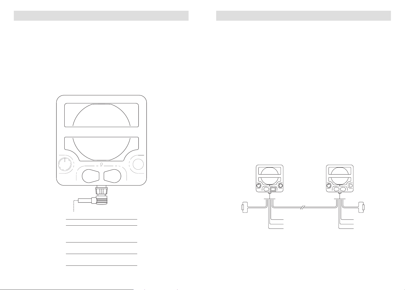
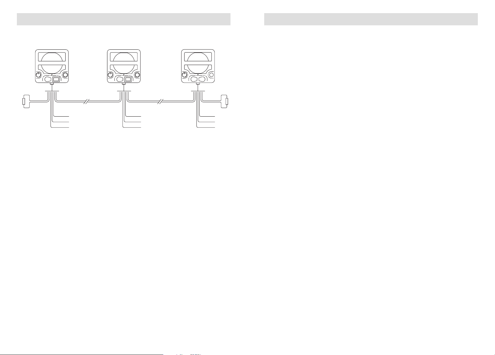
The 2-wire network is connected by wiring intercoms in series. The positive network
wire of one unit is connected to the positive network wire of the second unit. The
negative network wires are connected similarly. Network wires between units must
remain paired in a 2 conductor or more cable. Twisted pair wiring is preferred but
not required for all installations. Both two unit wiring and multiple unit wiring are
shown below. The ends of a network are always completed with a terminator.
The following are recommendations for all installations:
(Also see Appendix A – Network Installation Tips).
• Use Belden 9463 Twinaxial cable when possible.
• Keep network wire pairs together at all times.
• Connect network units in series.
• Do not splice additional wires into network cable runs.
• Do not bundle excess network cable.
Two Unit Wiring
BRN
BLU
YEL (+)
GRY (-)
DRAIN (CHASSIS GND)
TERMINATOR
CABLE (PROVIDED)
Wire Color Designation
GRY Power (-)
BRN
TERMINATOR
BLU
POWER
GRN
WHT
YEL (+)
GRY (-)
DRAIN (CHASSIS GND)
GRN
WHT
POWER
YEL Power (+)
DRAIN Chassis Gnd
WHT Net (-)
GRN Net (+)
BLU Net (-)
BRN Net (+)
6
7
Page 6
SYSTEM WIRING
OPERATION
Multiple Unit Wiring
MULTIPLE UNIT WIRING
BRN
TERMINATOR
BLU
POWER
GRN
WHT
YEL (+)
GRY (-)
DRAIN (CHASSIS GND)
GRN
WHT
POWER
BRN
BLU
YEL (+)
GRY (-)
DRAIN (CHASSIS GND)
BRN
BLU
POWER
YEL (+)
GRY (-)
DRAIN (CHASSIS GND)
Terminators
Two terminators are provided to complete a network circuit. The terminators are
located at both ends of a network. For optimal performance, install terminators
as close to the unit as possible and no further than 6 feet in wire length away.
Terminators are provided with every unit and available as an accessory (see
“Options and Accessories” section).
NOTE: Soldering terminators is recommend over butt splicing to assure a good
connection.
GRN
WHT
Without headset
Base station audio is sent over the network to other stations when the panel PTT is
depressed and sound is present on the microphone. When multiple stations are on
a network, a “first come, first served” principle is employed between base stations
with panel PTT buttons. Depressing a panel PTT button always disengages the
respective station’s speaker.
Remote stations employ voice activated microphones that transmit audio over the
network when sound is present at the microphone. Audio from other stations will
engage the remote unit speaker and disengage the remote unit microphone when
sent via a panel PTT button.
TERMINATOR
An automatic gain control is provided for every remote and base unit microphone.
When extremely high noise is present the transmitted audio level from that microphone will be lowered.
With headset
Headset usage provides hands-free full-duplex communications between stations. If
two stations are using headsets, they will be able to talk and hear each other without
depressing PTT buttons. Radio communication is possible with Firecom accessories
(see “Options and Accessories” section in this manual). Use only Firecom 10 series
headsets with red PTT buttons.
If a base station headset user is depressing the panel PTT and speaks into the headset microphone, the user’s voice will transmit over remote station speakers. If a
remote station is employing a headset and others are not, simply speaking into the
headset microphone will allow the user to be heard over other station’s speakers.
Radio Communications
Radio broadcast and reception are available with the addition of an analog interface
unit (see “Options and Accessories” section). Once an interface unit is installed on
a network, radio communication is possible at every unit on the network. Incoming
radio traffic will be heard on base station speakers and headsets at remote and
base stations, but not heard on remote station speakers. A Firecom 10 series headset
with red PTT button is required to transmit over the radio.
8
9
Page 7

TROUBLESHOOTING
TROUBLESHOOTING
When properly installed and powered, a pantherC series intercom network will
perform reliably even in a harsh environment. If you believe one or more of your
intercom units are malfunctioning, use the following troubleshooting information
to locate the problem.
NOTE: This is a network communication system. Problems at one unit may affect
audio quality at some or all other units. Troubleshooting should include power and
network connections at all units.
If the symptoms you are experiencing are not covered in this manual, or if you are
having difficulty troubleshooting your system, contact your local Firecom dealer for
assistance, or see www.firecom.com for additional information.
Problem: One or more intercoms are not working.
• Check that the status light is on for each intercom.
If status light is out:
Check that the power switch is on (if it has one).
Check that the station has power. (See “Installation” section.)
Check that the network wiring is connected properly, and pay special attention
to correct termination. (See “Installation” and Appendix A – Network
Installation Tips.)
Problem: Cannot hear voice traffic on the speaker of an intercom.
• If there is a headset connected to the intercom unit, disconnect it.
• Adjust the volume control on the intercom.
• Be sure you are not pressing the PTT button while you are trying to listen.
• Check if other users can hear you talk on the intercom. If you can talk on the
intercom but can not hear through the speaker, the intercom is malfunctioning
and should be serviced by an intercom technician.
Problem: Cannot talk through the intercom microphone.
• If there is a headset connected to the intercom unit, disconnect it.
• Be sure to press the PTT button when talking from a base unit.
• If you are trying to talk on a remote unit, be sure you are speaking loudly
enough to activate the voice-activated microphone.
Can you hear traffic on the intercom through the speaker?
• If you can’t talk or listen on the intercom, check the connection of the network
wires to your intercom unit.
Problem: When listening to an intercom with a headset, the sound is distorted or
intermittent.
• Clean the headset plug and jack with contact cleaner.
• Insert and remove the headset plug into the headset jack a few times to
remove oxide build up on the contacts.
• Confirm that you are using a Firecom10 series radio transmit headset.
• Check network wiring and termination.
Problem: Noise or static is heard over the network.
• Make sure the network connections are clean.
• Turn the unit off and back on after 5 seconds.
• Confirm shore power is disconnected to the vehicle on which you are installing
the intercom.
Problem: Audio can be transmitted to, but not heard by, other units.
• Check the terminators on the network. Make sure they are connected and have
the proper resistance.
• Check network wiring. Make sure all network wires remain in pairs and there
are no additional connections on any network run.
• Check for adequate power at all units.
• Check for a 5 amp fuse at all units.
Problem: Background noise is heard while a headset is plugged in.
• Confirm that you are using a Firecom 10 series radio transmit headset.
• Confirm that any remote unit has a Firecom 10 series radio transmit headset
plugged into it while in a high noise environment.
If a problem persists in a headset or intercom unit, contact Firecom for a Return
Merchandise Authorization (RMA) number. Return the headset or intercom for
replacement or repair.
CONTACT: Firecom 1-800-527-0555
7340 SW Durham Road
Portland, OR 97224
USA
10
11
Page 8
OPTIONS AND ACCESSORIES
MAINTENANCE
UH-10
Part No. 105-0192-00
Under-helmet radio transmit headset. Adjustable volume, noise-canceling electret
microphone, adjustable headstrap, flex-style boom rotates for left or right dress,
comfortable liquid foam ear seals. 24dB NRR. (Red PTT located on dome.)
UH-10S
Part No. 105-0196-00
Under-helmet headset, one slotted dome without speaker. Radio transmit capable.
Noise-canceling electret microphone, flex-style boom rotates for right or left dress.
(Red PTT located on dome.)
FH-10
Part No. 105-0190-00
Over-head radio transmit headset. Adjustable volume, noise-canceling electret
microphone, flex-style boom rotates for left or right dress, comfortable liquid foam
ear seals. 24dB NRR. (Red PTT located on dome.)
Terminators, Standard
Part No. 108-0051-00
Network terminators used with pantherC series 2-wire networks.
Qty (2) per package
Analog Interface, 30XXR Intercom and Single Radio
Part No. 108-0450-00
This unit allows the addition of a Firecom 30XXR intercom and an optional radio
to the pantherC series 2-wire network. With the integration of this unit, anyone on
the 2-wire network will be able to send and receive radio communications, as well
as talk to anyone on a Firecom 30XXR intercom.
Clean headset jacks as required.
APPENDIX A – NETWORK INSTALLATION TIPS
The following guidelines are recommended for a trouble free installation.
Network Cable
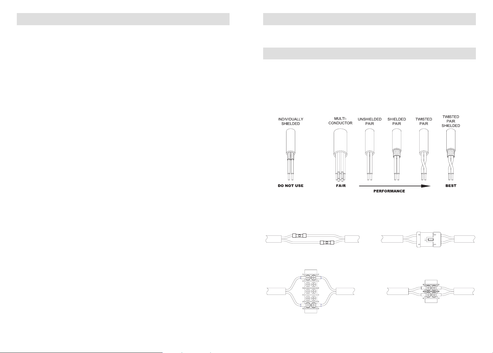
A wide variety of cabling will work for network wiring including multi-conductor
cabling. Do not use individually shielded conductors. When possible, we recommend Belden 9463 Twinaxial cable. If you are choosing cable from scratch, we
recommend cable with a nominal impedance in the range of 70 to 95 ohms.
Network Wire Connections
Connections on network cable should be kept in pairs. Do not route wires individually
or connect independently. Always treat both wires as a pair. What happens to one
wire should happen to the other wire at the same location.
HE-150
Part No. 108-0675-15
15' coiled headset extension cable for use with any single-plug headset for greater
mobility at pump panel position.
Network Cable, 2-wire
Part No. 108-0034-00 (50 feet)
Two conductor, one twisted pair network cable for panther network systems.
C1 and C2 Flush Mount Bracket
Part No. 108-0270-00
A mounting bracket for C1 and C2 units that allows for panel in insertion with only
the front bezel revealed.
12
DO NOT
Use non-aligned butt splices
DO NOT
Use far terminal connections
DO
Use 2-conductor automotive connections
DO
Use near terminal connections
13
Page 9
APPENDIX A – NETWORK INSTALLATION TIPS
APPENDIX A – NETWORK INSTALLATION TIPS
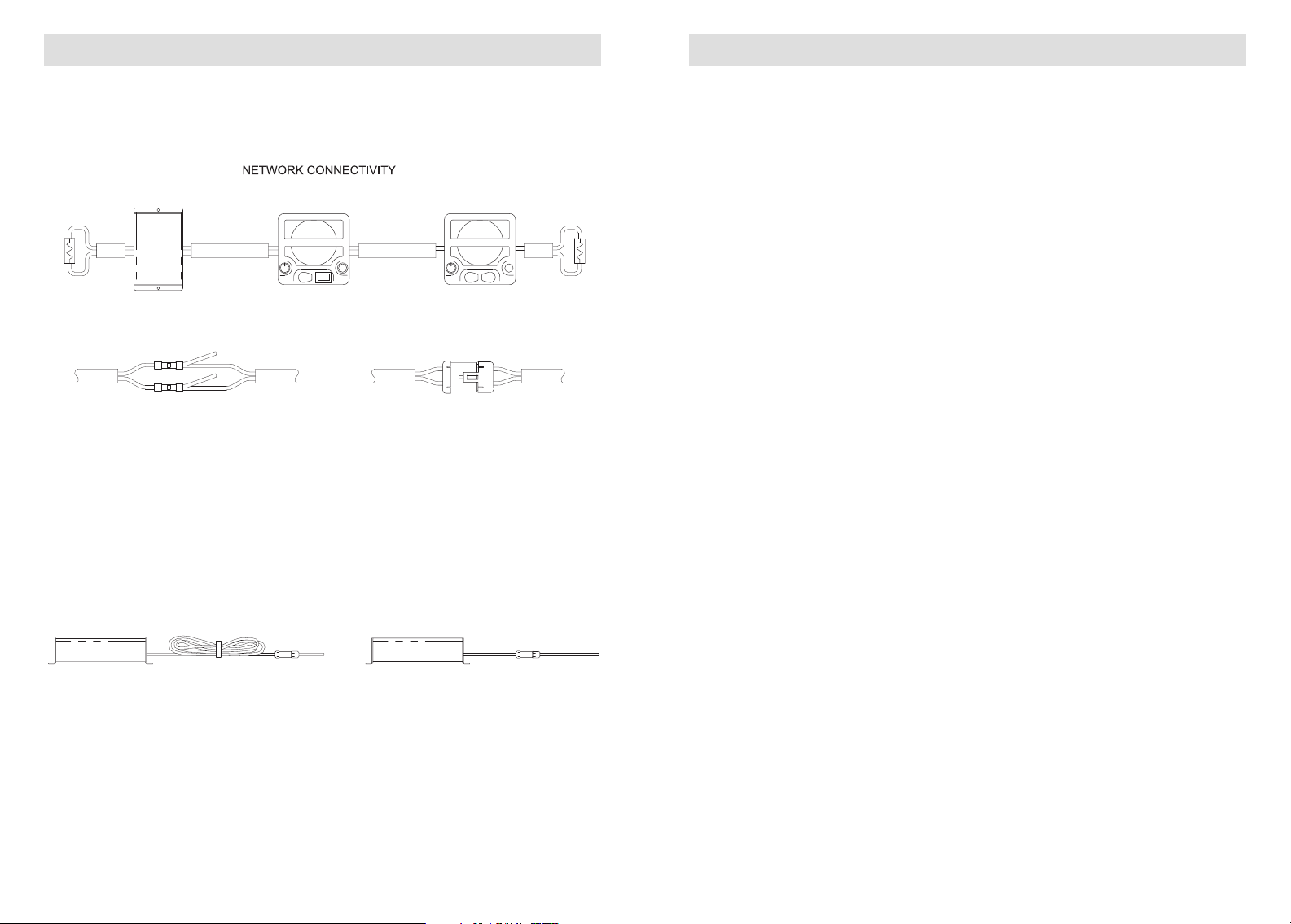
Connecting Network Units
Never splice into network wires. All units come with network in and out connections.
Wire all units in series with terminators at both ends.
DO NOT
Splice additional wires into network cables
Direct Network Wiring
Do not bundle excess network wiring. Choose direct routes for network cables and
remove all excess cable.
DO
Connect using 2-conductor connectors
1. Network wires must remain in pairs.
The most important item to remember when installing a pantherC series network
system is to keep the network wires as a pair; retaining a close proximity between
the two conductors. A twisted pair is preferred, but not required. When using a
terminal block, connect the wire pair to terminals directly next to each other.
When passing through collector rings or other similar devices, use conductors that
are next to each other.
2. Network spurs are not permitted.
A network pair from one unit to the next, or to a terminator, should contain only
the two wires running directly between units with no spur routes or additional
wires spliced into the run. The units in a network are connected in series. When
retrofitting a pantherC series system into a previously installed wiring system, it is
important to trace the wiring and confirm that no additional wires have been
spliced into the intended network wires.
3. Identical wire treatment.
Both wires of a network pair should be treated identically. The wires should be of
equal length and terminated in the same manner. If one wire is connected at a
block or in-line splice, the other wire of the pair should be connected at the same
point and in the same manner, keeping the wires close together. When retrofitting
a system into a previously installed wiring system, it is important to trace the wiring
and confirm that both conductors of the wire pair are of equal length and treated
identically.
4. Avoid non-essential splices.
When possible, avoid splices on the network. When splices or termination is
required, make sure both wires of the pair are treated identically.
5. Ground shields at one end only.
Cable shielding is recommended but not required. When using shielded cable,
ground the shield at one end of the cable only.
DO NOT
Bundle excess cable
14
DO
Cut cables to length
6. Avoid bundling excess wire.
Excess network wire should be removed and not bundled. Sharp bends or kinks
in network wire can be harmful. Typical minimum bend radius for network wiring
is in the 2 to 3 inches range. See cable manufacturer for recommended minimum
bend radius.
7. Avoid 3-phase power cables and fluorescent lights.
Keep all network wires 1 foot away from 3-phase power and fluorescent lights.
15
Page 10
APPENDIX A – NETWORK INSTALLATION TIPS
WARRANTY
8. Impedance mismatches are harmful.
The pantherC series network system is designed to handle imperfections, but
repeated poor network treatment can cause communication failure. Every change
in impedance along the network path causes a little degradation to the network.
Minor impedance changes can be managed but large jumps in impedance or
repeated changes can cause the system to not work correctly.
9. Poor network wiring is accumulative.
The pantherC series network system is designed to handle imperfections, but
repeated poor network wiring treatment can cause communication failure. A
network wiring problem that does not show up on a small system may cause a
failure when additional units are added and the network is expanded. Whenever
a system is modified, the entire network system should be reviewed per the above
rules. Network runs can be several hundred feet when handled properly.
10. Use Firecom 10 series headsets only.
When using headsets with the pantherC series system, use Firecom's UH-10,
UH-10S, FH-10, or FH-10S headsets. Headsets are ideal for troubleshooting in
a high noise environment or enclosed building that can cause feedback
between units.
11. Continuity checks are not enough to verify network wiring.
When troubleshooting a system or retrofitting using previously installed wiring, it
is important to keep in mind that a continuity check is not a conclusive test of a
network wire run. Each wire must have continuity, but that is not enough. Wiring
must also follow the strict pairing rule outlined above.
12. One network issue can affect everyone on the network.
A poor network wire or network treatment can affect all units on the network, not
just the unit closest to the problem.
Two-Year Limited Warranty to the Original Purchaser
Sonetics Corporation warrants to the original purchaser of its products, that they will be free
from defects in materials and workmanship, under normal and proper use, for the period of
two years from date of purchase. Sonetics Corporation will repair or replace, at its option, any
parts showing factory defects during this warranty period, subject to the following provisions.
This warranty applies only to a new product which has been sold through authorized channels
of distribution. All work under warranty must be performed by Sonetics Corporation. All
returned products must be shipped to our address, freight prepaid, accompanied by a dated
proof of purchase. The purchaser voids this warranty if he, she or others attempt to repair, service
or alter the product in any way. This warranty does not apply in the event of accident, abuse,
improper installation, unauthorized repair, tampering, modification, fire, flood, collision, or
other damage from external sources, including damage which is caused by user replaceable
parts (leaking batteries, etc.). This warranty does not extend to any other equipment or apparatus
to which this product may be attached or connected. The foregoing is your sole remedy for
failure in service or defects. Sonetics Corporation shall not be liable under this or any implied
warranty for incidental or consequential damages, nor for any installation or removal costs or
other service fees. This warranty is in lieu of all other warranties, express or implied, including
the warranty of merchantability or fitness of use, which are hereby excluded. To the extent that
this exclusion is not legally enforceable, the duration of such implied warranties shall be limited
to two years from date of purchase. No suit for breach of express or implied warranty may be
brought after two years from date of purchase.
13. Bypassing a network wiring run is a quick way to isolate problems.
Bypassing a suspected section of wire with an independent external network can
often provide the fastest network wire test between units. When testing, make sure
the suspect wiring is completely removed from the system. If the problem goes
away after you have bypassed a section of network wire, then look for a wiring
problem in that section.
16
WARNING
Safety Information
Firecom’s pantherC series intercom speaker is loud enough to cause hearing damage. Use the
volume control provided on the intercom to reduce the speaker volume to a safe level for the
environment in which the intercom is being used or use Firecom headsets to reduce noise.
17
 Loading...