

Page 1
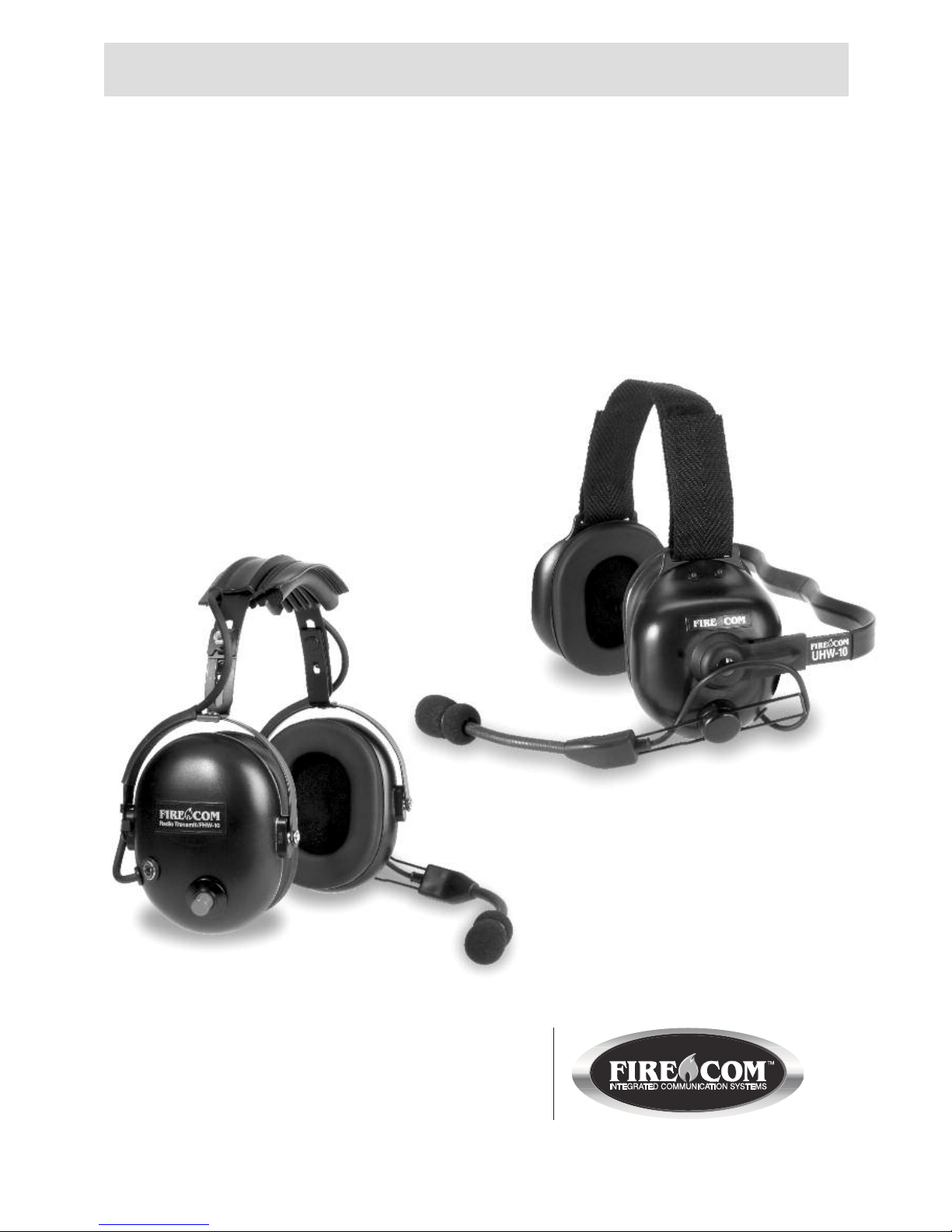
Wireless Headset Series
UHW-Series Under the Helmet
FHW-Series Over the Head
Operation Manual
7340 SW Durham Road • Portland, OR 97224 USA
Phone: 503-684-6647 • 1-800-527-0555
Fax: 503-620-2943 • email: [email protected]
www.firecom.com
Page 2

Page 3
1
Introduction
The UHW/ FHW series are highly reliable wireless communication headsets for fire and
emergency truck operator applications. The UHW/ FHW series provides secured, digitally
encoded interference free communications. When operated as part of a wireless system,
up to 50 headsets can operate interference free in close proximity to each other.
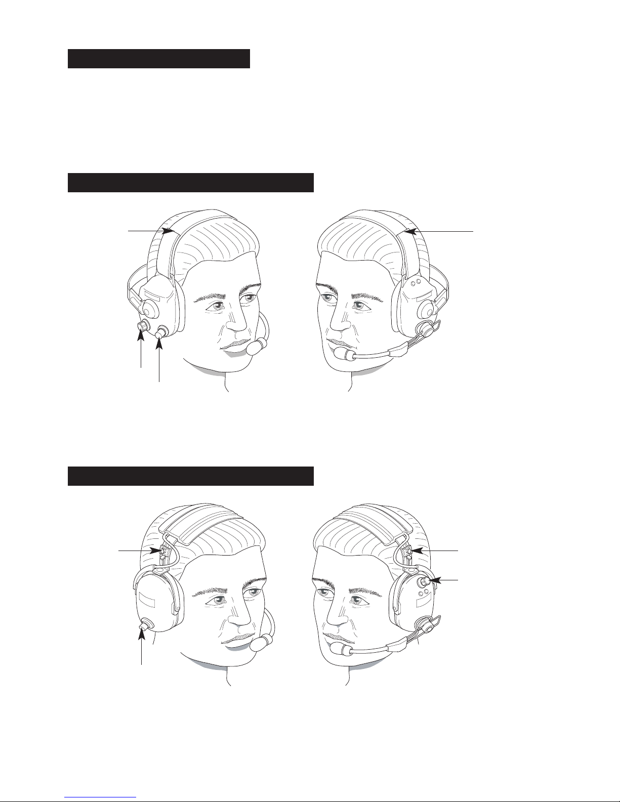
Under-the-Helmet Headsets
A
djustable
headstrap
Volume control
Push-To-Talk (PTT) button
Adjustable headstrap
UH
Over-the-Head Headsets
Push-To-Talk (PTT) button
Volume control
Adjustable headband
Adjustable
headband
FH
Page 4

2
Proper Fit
When worn properly, this headset will provide significant hearing protection. If it is not worn
properly, the headset’s effectiveness in reducing harmful noise is severely compromised.
• The length or vertical fit of the headset ear dome is adjusted by the headband or head strap. Adjust as necessary to achieve a fit that ensures the headset ear dome completely
covers the ear.
• For maximum comfort, wear the headset as far back on the head as possible, while ensuring the ear dome still completely covers the ear. If discomfort is felt in the jawbone, you are
wearing the headset too far forward.
Caution
This Firecom headset provides 24dB noise attenuation when properly fitted to the user and
worn as instructed. Any modification to the hearing protector such as drilling holes in the
dome, painting or reforming the headband spring, will negatively impact the hearing protector’s
performance and hearing damage could occur.
Federal law requires the following statements:
“Although hearing protectors can be recommended for protection against the harmful effects
of impulsive noise, the Noise Reduction Rating (NRR) is based on the attenuation of continuous noise and may not be an accurate indicator of the protection attainable against impulsive
noise such as gunfire.”
“The level of noise entering a person’s ear, when a hearing protector is worn as directed, is
closely approximated by the difference between the A - weighted environmental noise level
and the NRR.
Example
1. The environmental noise level as measured at the ear is 92dBA.
2. The NRR is 24dB.
3. The level of noise entering the ear is approximately equal to 92dB (A) – NRR or 68dB.
Caution
For noise environments dominated by frequencies below 500 Hz, the C - weighted environmental noise level should be used.
Always wear a hearing protector in areas that have been identified as high noise locations.
Page 5

3
Headset Power Switch and Volume Control
A power switch is provided on the volume control. This control is located on the right ear
dome on the UHW headsets, and on the left ear dome on the FHW headset. Volume should
be set at a comfortably high audio level to optimize performance but not so high as to cause
audio distortion and hearing discomfort.
Operation
The base station should be installed and powered up prior to operating the headset. If the
headset has not been previously paired to the base station, refer to the “Pairing Section” for
instructions. Turn the power switch on, the green LED will flash rapidly to indicate that the
headset is attempting to link to the base. The link LED on the base station will also be flashing
rapidly at this point. After approximately 5 seconds the headset will link to the base and the
green LED will turn on steadily to indicate that the headset is linked to the base. The headset
will also sound a one time double-beep on connection to the base. Once the connection is
established, full duplex communication between the base station and the headset will become
possible.
Out-of-Range Warning
All wireless headsets incorporate an out-of-range warning to warn the user against exceeding
the coverage range of the headset. The headset will sound a 1 second cautionary beep every
10 seconds when the headset is at the fringes of the coverage range and before the headset
goes completely out of range and looses its link to the base. The cautionary beep will stop if
the user steps back into range from the base station.
Warning: Firecom recommends that the headset always be operated
within the coverage range to ensure consistent and clear communications
to ensure the safety of the crew and help them perform their duties in the
safest and most effective manner.
Reconnect Feature
Should the headset go out of range and loose its link to the base station, the headset is
capable of automatically reestablishing its link to the base within 10 -15 seconds of the headset’s coming back into range. However, if the headset is not able to reconnect to the base
station within 5 minutes of loosing its link, the headset will be timed out and powered down
automatically. The user will then have to cycle power to the headset in order to reestablish
the link to the base station.
Page 6
4
No more than
1/8" from lips
Microphone Placement
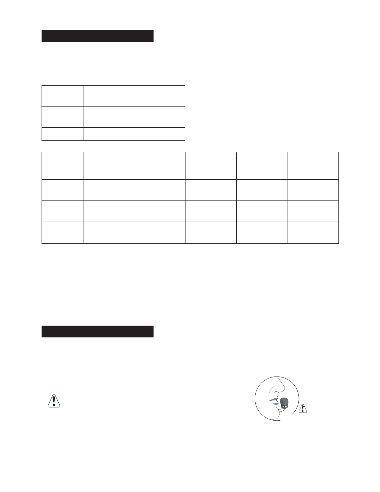
Place the microphone in front of the mouth and no more than 1/8" away from the lips as
shown in the diagram below. Placement of the microphone is critical for proper operation of
the noise gating feature.
If the microphone is positioned incorrectly, you
may experience a reduction or interruption in the
audio and or deterioration in clarity of intercom
and radio communication.
LED Indicators
All headsets have one green and one red externally viewable LED indicator located on the left
ear dome (same side as boom microphone).
These two LEDs operate as follow:
Unit Off,
Charging:
Green
LED
Red LED
Steady ON
Fully Charged
Charging
Flashing
Slow
Unit On:
Green
LED
Red LED
Audible
Steady ON
Connected
to Base
Flashing
Slow
Flashing
Fast
3 Beeps
Every 10
Minutes
6 Beeps
Every
Minute
Not Connected
to Base
Very Low
Battery
Very Low
Battery
Low Battery
Low Battery
Page 7
5
Mic Muffs
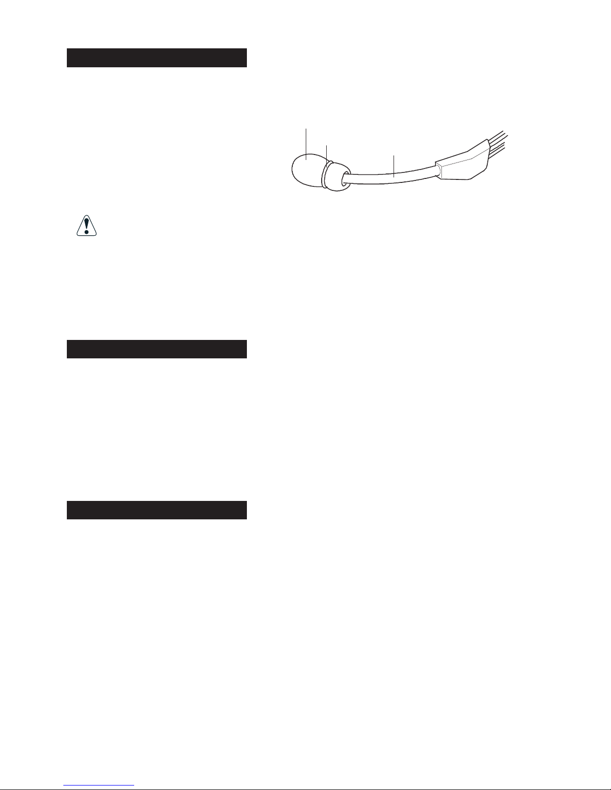
The headset microphone is covered with a washable, replaceable foam mic muff. This mic
muff helps prevent the “pops” and “hisses” that can occur from speaking into a microphone
that is close to the mouth.
To clean or replace the mic muff:
1. Remove the o-ring.
2. Slip the mic muff off the microphone.
3. At this time, you can decide whether
to clean or replace the mic muff.
If you clean the mic muff, use a mild detergent, rinse it out well and let it
dry completely before re-installing it on the microphone.
4. Slide the mic muff on the microphone.
5. Install the o-ring on the mic muff to secure it.
Replacement mic muffs may be ordered from Firecom.
Intercom Communication
Model-10; has a red momentary PTT button. The microphone is always live for intercom
communication. Press and hold PTT to transmit over vehicle radio.
Model-20; has a black momentary PTT button. Press and hold PTT to activate the microphone for intercom communication. Radio transmitting is not possible with the -20 models.
Model-40; has a white momentary PTT button. Press and release PTT to activate the microphone for intercom communication. Radio transmitting is not possible with the -40 models.
Pairing Procedure
1. Press and hold the pairing button on the front panel of the base station for approximately
5-7 seconds until the yellow LED(s) on the front panel of the base station start flashing,
indicating that the base station has entered pairing mode. Once the base station is placed
in pairing mode, the user has approximately15 seconds to place the headset in pairing mode.
2. Press and hold the PTT button, turn on power to the headset. After approximately 5 seconds,
the green and red LEDs on the outside of the left ear dome will start flashing in a relatively
fast alternating pattern. Release the PTT button.
3. Monitor the green and red LEDs on the left ear dome of the headset. After about 5-7
seconds, the alternating flashing pattern ends, the green LED will flash rapidly for two seconds
and then the green and red LEDs resume normal operation (as stated in the section titled
“LED Indicators”) to indicate that the headset is paired and linked to the base station. The
respective LINK LED on the base station will illuminate steadily after flashing rapidly for
two seconds to indicate that a link to the headset has been established.
Mic muff
O-ring
Mic boom
Page 8
6
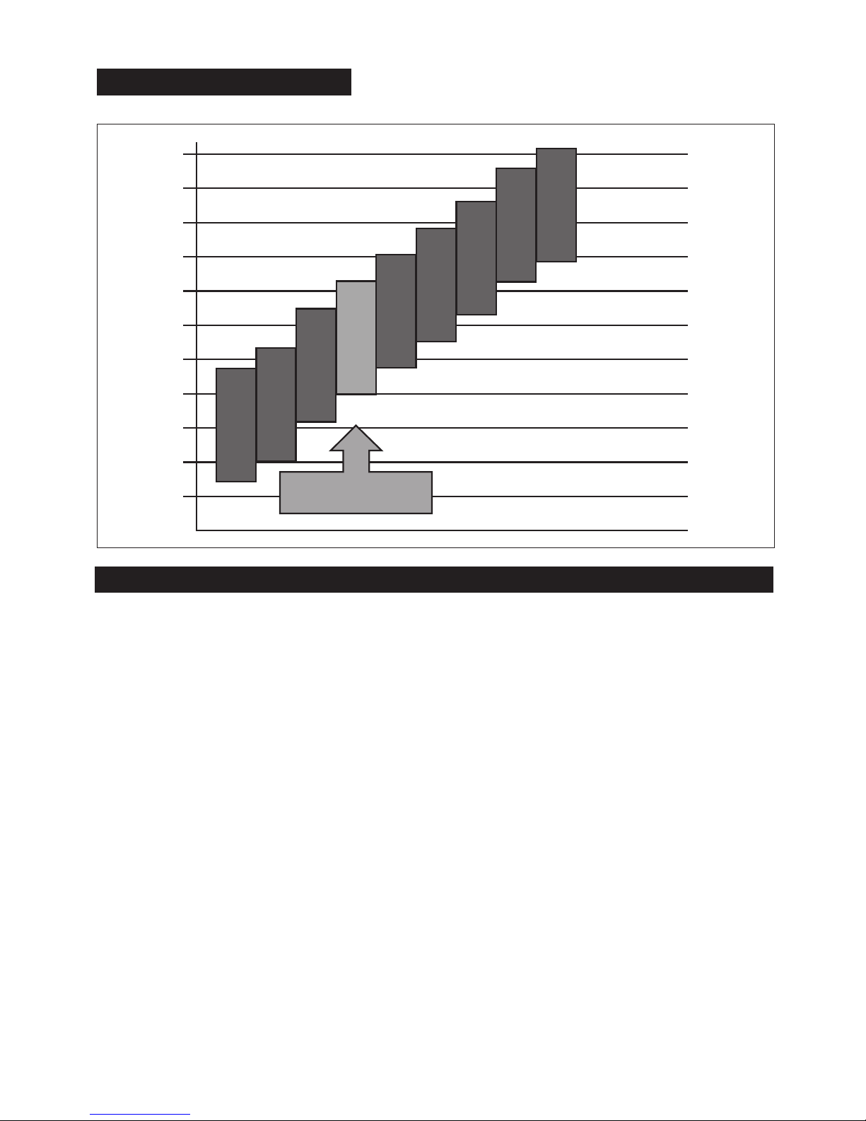
Headset Microphone Volume & Noise Gate Threshold Adjustment Procedure:
1. With the headset power off, hold down the PTT button.
2. Turn power on to the headset, release the PTT button within 3 seconds after the red LED
turns off; the red LED will flash 3 consecutive times to indicate microphone adjustment
mode is active.
3. Wait until the headset connects to its host base station.
4. Press the PTT button momentarily then release; the number of times the red LED flashes
indicates the level of microphone volume and Noise Gate Threshold settings combination.
The higher the number of flashes, the lower the microphone volume and the higher the
Noise Gate Threshold. There are nine settings available depending on the average ambient
noise levels as indicated in the graph above.
5. To test the selected setting, without exiting microphone adjustment mode, turn power off
momentarily (a few seconds) to the headset, then turn it back on.
6. Test the microphone to see if you have chosen the desired microphone sensitivity /Noise
Gate Threshold combination. If not, repeat steps 4-6.
7. To save the desired setting and exit adjustment mode, turn headset power off, wait until
the headset disconnects from the base station.
8. Turn headset power on without holding the PTT button, the headset will enter normal
operating mode and connect to the base station.
13 0 d B
125d B
120 d B
115dB
110dB
10 5 d B
100dB
95dB
90dB
85dB
80dB
13 0 d B
125d B
120 d B
115dB
110dB
10 5 d B
100dB
95dB
90dB
85dB
80dB
1
2
3
4
5
6
7
8
9
Factory Setting
Mic Gain Range
Page 9
7
Charging
Ensure that the headset is fully charged prior to operating for the first time.
Wireless headsets have a charger jack located on the right ear dome. A charger cable
assembly is provided with the headset. The unterminated end of the charger cable shall be
wired to a fused slot in the vehicle’s fuse box using the fuse holder assembly and 500mA fuse
supplied. Plug the terminated end of the charger cable into the headset charger jack (refer to
the “LED Indicators” section for proper operation of the battery charging red LED indicator).
NOTICE: FUSE ASSEMBLY INSTALLATION
Firecom fuse holder is to be installed within 18" from the battery source in-line with your
charging cable assembly when power from a vehicle is used for recharging your wireless
product.
Only use a 500mA fuse (supplied) with the charging cable assembly.
NOTES:
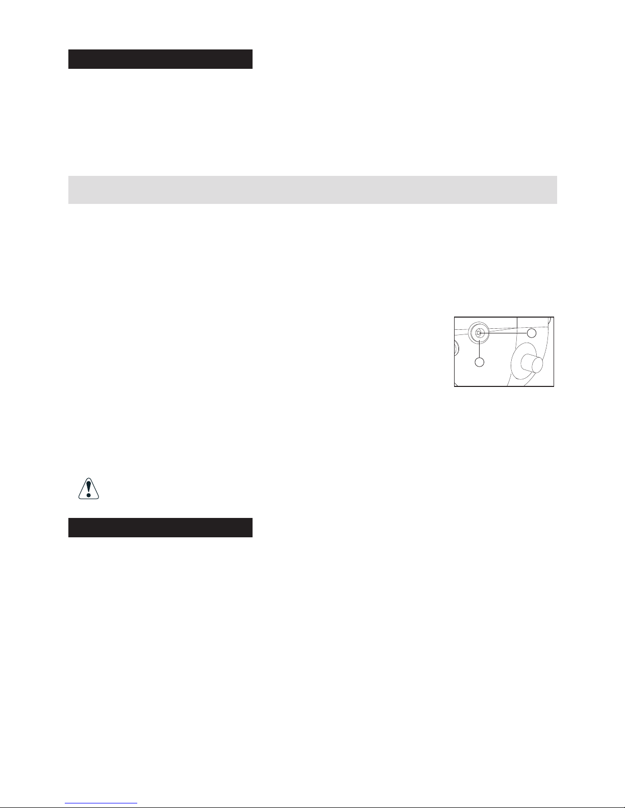
1. Observe correct polarity when connecting the charger cable
to 12V from the vehicle. Connect the white striped black wire
to +12V and the solid black wire to GND. This will result in a
positive center terminal of the 2.1mm charger jack as shown
in the illustration.
2. Firecom does not recommend operating the headset while the headset is being
charged. It is recommended that the headset be charged only when it’s not
being operated and with the power switch on the headset turned off.
Firecom recommends charging the wireless headset using the supplied
9VDC regulated wall adapter, when possible.
WARNING! The use of an unregulated wall adapter will damage the
charging circuit and components and will void the warranty.
Reset
In rare cases, resetting the headset may become necessary.
With the power switch turned on, plug the charger plug into the charger jack on the right ear
dome. The system will reset, both red and green LEDs will illuminate for approximately two
seconds after which the headset will resume normal operation.
NOTES:
1. In case the battery is deeply discharged, no LED indication will be possible until
the battery is partly charged to an operable voltage level.
2. Plugging the charger plug into the headset at anytime will cause the headset
to reset even when the headset is linked to a base station. Resetting a
connected headset will result in losing the link for about 10 -12 second
+
–
Page 10

8
Care and Maintenance
To ensure hearing protection and user safety, repairs or replacement of the headset should be
immediately sought if you see any defect such as holes or cracks in the ear domes, ear seals
or headband.
Body oils, perspiration and hair care products will, over time, affect the ear seals. Inspect the
ear seals frequently for signs of wear and replace at approximate 6 month intervals along with
the mic muff (cover).
Do not remove the foam speaker cover
Never remove the charging cable from the headset by pulling on the cord.
The headset should be unplugged at the jack location by pulling the
charger plug from the jack.
Wipe headset and ear seals with a mild soap and water mixture only. NEVER IMMERSE
ANY PART OF THE HEADSET IN WATER. Although the microphone is water resistant, to
ensure a longer life, keep the microphone away from moisture, when possible.
Do not store in direct sunlight or in areas of high temperature.
Specifications
Headset
Sensitivity . . . . . . . . . . . . . . . . . . . . . . . . . . . . . . . .104dB re 20 uPa @ 1000 Hz, 1 mW
Frequency Response . . . . . . . . . . . . . . . . . . . . . . . . . . . . . . . . .300Hz - 3.4 KHz,+/- 3dB
Impedance . . . . . . . . . . . . . . . . . . . . . . . . . . . . . . . . . . . .32 ohms nominal per speaker
Weight (FHW-Series) . . . . . . . . . . . . . . . . . . . . . . . . . . . . . . . . . . . . . . . . . . . . . .19.50z
Weight (UHW-Series) . . . . . . . . . . . . . . . . . . . . . . . . . . . . . . . . . . . . . . . . . . . . . .17.80z
Microphone
Frequency Response . . . . . . . . . . . . . . . .Optimized for speech clarity and noise reduction
Max. Amb. Noise Level . . . . . . . . . . . . . . . . . . . . . . . . . . . . . . . . . .125dB SPL re 20 uPa
MIC Sensitivity . . . . . . . . . . . . . . . . . . . . . . . . . . . . . . . . . . . . . .-44+/- 5db, 0dB=1v / Pa
DC Bias . . . . . . . . . . . . . . . . . . . . . . . . . . . . . . . . . . . . . . . . . . . . . . . . .Internally biased
Frequency range . . . . . . . . . . . . . . . . . . . . . . . . . . . . . . . . . . . . . . . . . .300Hz – 3.4KHz
Noise Canceling . . . . . . . . . . . . .approx. 6.25 db /octave from 3.4 KHz down to 300 Hz
S / N ratio . . . . . . . . . . . . . . . . . . . . . . . . . . . . . . . . . . . . . . . . . . . . . . . .60db minimum
Impedance . . . . . . . . . . . . . . . . . . . . . . . . . . . . . . . . . . . . . . . . . . . . .Internally matched
RF
- Range: 1500' open field.
- Digital encoding for secured communications.
- Interference free communications for up to 50 headsets operating in close proximity.
- Immunity to interference from other communications devices operating in the entire
frequency spectrum from 30 MHz – 18 GHz.
Page 11

9
Power
- 3.7 V rechargeable lithium polymer battery
- >10 hour battery life when operating
- Over voltage, under voltage, over current and over temperature protection
- Charge source: 12 V nominal (9V-16V), 150mA minimum
- Charge time: 5 hours at 9V
Environmental
- Operating temperature -10 to+70oC
- Storage temperature -25 to +85oC
- Meets standards SAE J1455 and J1113
- Chemical resistance to corrosion and humidity per MIL-STD-810
FCC/IC Compliance
This device complies with FCC Part15 Rules and IC RSS-213 Rules. Operation is subject to
the following two conditions:
1 This device may not cause harmful interference.
2. This device must accept any interference that may be received, including interference that
may cause undesired operation.
FCC/IC RF Exposure Warning
- This product complies with FCC radiation exposure limits set forth for an uncontrolled
environment.
- This product may not be collocated or operated in conjunction with any other antenna or
transmitter.
- This headset has been tested and meets the FCC RF exposure guidelines. Max. SAR is
0.003 W/ kg.
Changes or modifications not expressly approved by Firecom can void the user’s
authority to operate the equipment.
Page 12

FIRECOM is a division of Sonetics Corporation
7340 SW Durham Road • Portland, Oregon 97224
800-527-0555 • 503-684-6647 • Fax: 503-620-2943
Email: [email protected] • www.firecom.com
Copyright © 2010 Sonetics Corporation - All rights reserved.
The information in this document is subject to change without notice.
No part of this document may be reproduced in any form without prior written consent of Sonetics Corporation.
This document is part number 600-0074-00 RevD.
Warranty
Two-Year Limited Warranty to the Original Purchaser
Sonetics Corporation warrants to the original purchaser of its products, that they will be free
from defects in materials and workmanship, under normal and proper use, for the period of two
years from date of purchase. Sonetics Corporation will repair or replace, at its option, any parts
showing factory defects during this warranty period, subject to the following provisions.
This warranty applies only to a new product which has been sold through authorized channels
of distribution. All work under warranty must be performed by Sonetics Corporation. All returned
products must be shipped to our address, freight prepaid, accompanied by a dated proof of purchase. The purchaser voids this warranty if he, she or others attempt to repair, service or alter the
product in any way. This warranty does not apply in the event of accident, abuse, improper
installation, unauthorized repair, tampering, modification, fire, flood, collision, or other damage
from external sources, including damage which is caused by user replaceable
parts (leaking batteries, etc.). This warranty does not extend to any other equipment or apparatus to
which this product may be attached or connected. The foregoing is your sole remedy for
failure in service or defects. Sonetics Corporation shall not be liable under this or any implied
warranty for incidental or consequential damages, nor for any installation or removal costs or
other service fees. This warranty is in lieu of all other warranties, express or implied, including
the warranty of merchantability or fitness of use, which are hereby excluded. To the extent that
this exclusion is not legally enforceable, the duration of such implied warranties shall be limited
to two years from date of purchase. No suit for breach of express or implied warranty may be
brought after two years from date of purchase.
 Loading...