

Page 1
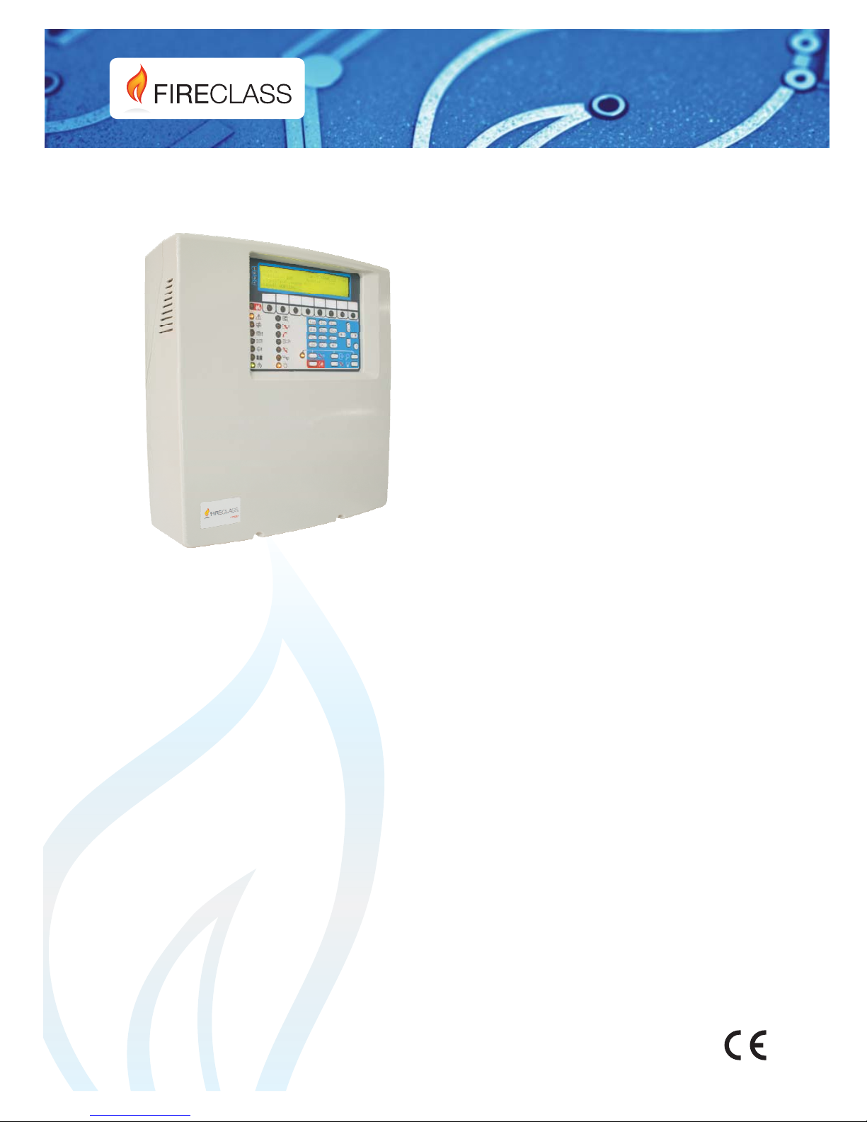
FC501
www.fireclass.net
Addressable
Fire
Control Panels
Installation Manual
Page 2
This Fire Control panel can only be programmed using
the Software FireClass Console release 1.0 or higher.
Control panel FW ver. 1.0 or higher.
TYCO shall not assume the responsibility for damage
arising from improper application or use.
Installation of this Control panel must be carried out
strictly in accordance with the instructions described in
this manual and in compliance with the local laws and
bylaws in force.
The FC501-L, FC501-H and FC501-HK Fire Control
panels comply with the essential requirements of stan
-
dards EN54-2; EN54-4 and EN54-21.
Contents of the box
The control panel is contained in a box. Listed below
are the contents:
Ø
the plastic cabinet (backplate and cover) with the
motherboard and the power supply Switching as
-
sembled.
Ø
The Quick Start Guide.
Ø
A transparent plastic bag containing:
- A CD-ROM containing the Installation and User
manuals and the FireClass software console to
manage the panel;
- A second transparent plastic bag containing:
-the KST thermal Probe;
- Two 3.9 kOhm resistors;
- a red and a black cable L = 300 mm with a faston
terminal to connect batteries;
- a black cable L = 300 mm with two faston terminal to
connect batteries. Proceed carefully to unpack the
contents and dispose of recyclable materials in accordance with the local law.
Recycling information
The manufacturer recommends that customers dispose of their used
equipment (panels, detectors, sirens, and other devices) in an environmen
-
tally sound manner. Potential methods include reuse of parts orwhole prod
-
ucts and recycling of products, components, and/or materials.
Waste Electrical and Electronic Equipment (WEEE)
Directive
In the European Union, this label indicates that this product
should NOTbe disposed of with household waste. It should be depos
-
ited at an appropriate facility to enable recovery and recycling.
NOTE- The FC501 Fire control panel can support several address
-
able devices (Detectors, Modules, Manual call Points, etc). The pres
-
ent manual includes the instructions for their programming, but for
further information on those devices and their accessories, please
visit: www.fireclass.net, logging in the Reserved Area, under Instal
-
lation Manuals.
The manufacturer reserves the right to change the technical specifi
-
cations of these products without prior notice.
0051
Tyco Fire & Security GmbH
Victor von Bruns-Strasse 21
8212 Neuhausen am Rheinfall
Switzerland
13
DoP-2015-4218 (FC501-L)
DoP-2015-4219 (FC501-H)/(FC501-HK)
EN 54-2:1997+A1:2006 EN54-4: 1997+A1:2002+A2:2006 EN 54-21
Control and indicating equipment with integrated power supply
equipment for fire detection and fire alarm systems for buildings
with alarm transmission and fault warning routing equipment.
EXPECTED OPTIONS
Fault signals from points
Dependencies on more than one alarm signal: type A and B
Delays to outputs
Disablement of addressable point
Test condition
Output to fire alarm device
EN 54-2 ESSENTIAL CHARACTERISTICS
Performance under fire conditions Passed
Response delay (response time to fire) Passed
Operational reliability Passed
Durability of operational reliability, Temperature resistance Passed
Durability of operational reliability, Vibration resistance Passed
Durability of operational reliability, Electrical stability Passed
Durability of operational reliability, humidity resistance Passed
EN 54-21 ESSENTIAL CHARACTERISTICS
Performance of transmission Passed
Operational reliability Passed
Durability of operational reliability, Temperature resistance Passed
Durability of operational reliability, Vibration resistance Passed
Durability of operational reliability, Electrical stability Passed
Durability of operational reliability, humidity resistance Passed
EN 54-4 ESSENTIAL CHARACTERISTICS
Performance of power supply Passed
Operational reliability Passed
Durability of operational reliability, Temperature resistance Passed
Durability of operational reliability, Vibration resistance Passed
Durability of operational reliability, Electrical stability Passed
Durability of operational reliability, humidity resistance Passed
0051
Tyco Fire & Security GmbH
Victor von Bruns-Strasse 21
8212 Neuhausen am Rheinfall
Switzerland
13
DoP-2015-4211 (FC500IP in FC501-L/FC501-H/FC501-HK)
EN 54-21
Alarm transmission and fault warning routing equipment for fire
alarm systems installed in buildings.
EN 54-21 ESSENTIAL CHARACTERISTICS
Performance of transmission Passed
Operational reliability Passed
Durability of operational reliability, Temperature resistance Passed
Durability of operational reliability, Vibration resistance Passed
Durability of operational reliability, Electrical stability Passed
Durability of operational reliability, humidity resistance Passed
The Declarations of Performance (DoP) can be found
on the product webpage at www.fireclass.net
.
Page 3

TABLE of CONTENTS
INTRODUCTION 5
FC501 Fire Control Panel 5
Accessory Items 5
Description 5
Input 5
Outputs 5
Operating Features 6
Interface 8
Access to Signalling and Commands 8
Users and Installers Features 9
Power Supply 9
Description of the FC500REP Repeater Signalling
10
FC500REP Repeater Control keys 10
FC500REP Repeater LED description 10
Description of the Control keys (Panel) 11
The status LED 12
PARTS IDENTIFICATION 13
Description of Parts 14
INSTALLATION 17
Installing the Control panel 17
Control panel closure 17
Installing FC500REP Repeater 19
Description of the Terminals 19
Loop 19
Telephone line 19
Fire 19
Fault 20
Audio station 20
Auxiliary outputs 20
RS485 21
Battery 21
The System Wiring 21
Connecting Addressable Devices 21
Connecting Repeater FC500REP 22
Connecting Output Devices 24
Bell Outputs 24
Connecting the Power Supply 25
Thermal Probe 26
Installing FC500IP board 27
Installing the 38Ah battery metal Box 28
Maintenance 28
PC PROGRAMMING 31
Installation 31
Select language 31
Software window Look 31
Control panel connections 31
Main window 32
Icons 32
File menu 32
Tools menu 33
Help Menu 33
Panel Details 33
Panel Details Menu 33
Communication Menu 34
Language Menu 34
Firmware Update menu 35
ScreenSaver menu 35
Account Menu 35
Programming Pages 36
Loop Devices programming 36
Description of the icons in the tool bar. 36
Loop wiring Calculation 37
Detectors parameters programming 37
Input module parameters programming 38
Output module parameters programming 39
Multiple Input-Output Module - Parameters
Programming (FC410MIO/FC410QIO) 40
Manual Call Point parameters programming 40
Zones programming 41
Outputs Programming 42
SC1, SC2 Outputs 42
OC1, OC2 Outputs 42
Relay Outputs 43
General Options programming 43
General Output Settings 45
Panel Setting for Simphony Sounders and Panel
setting for AV Base Sounder 45
Communicators Programming 45
Clock 47
Log 47
Utilities 48
Battery Calculation 48
User mode 49
Graphic Maps 50
Disable 50
PROGRAMMING FROM THE PANEL 53
Using the system 53
Operating the system from the Panel 53
Alphanumeric entry (Editing text) 53
Assistant text composition 54
Single Selection 54
Multiple Selection 54
Date and Time 54
Numeric entry 54
Page 4

Main Page - Accessing the system 55
Insert password 55
Programming Page 56
0 KEY - Insert Modify password 56
1 KEY- Auto Enrolling (Autolearning) 57
Automatic zones assignment 57
Sounders Triggered by 58
Warning Enrolling (Autolearning) 58
Auto addressing procedure 59
2 KEY -Device 60
Choose the Loop (see User Manual View Devices)60
Choose the Device 60
Loop devices programming page 60
3 KEY - SW zone 61
SW zone in WALK TEST 61
Sounders on (3s) 62
Smoke delay (60s/30min) 62
Delay to Alarm 62
DLY ALARM TIME (min) 62
4 KEY- OUTPUT 63
Choose Output 63
SET AS SC1 63
PANEL ALARM TRIGGER? 63
DISABLEMENT TRIGGER? 63
5 Key- Network 64
6 KEY - MAP DEVICE 65
7 KEY -USB 65
8 KEY -SYSTEM 66
Panel ID 66
Day / Night / Auto 66
Delay to alarm time 67
Copy on Zone? 67
MONST. OUTPUT TIME 67
ENABLE SCREEN SAVER 67
2 Wire Loops 67
9 KEY- Restore Default 68
FC500REP Repeater Address 68
MODIFY 69
Accessing the Modify Menu 69
DISABLE 71
Accessing the Disable Menu 71
7 Key - Password (Disable) 71
Select the Password 71
Disable Password 71
9 Key- Sounders 71
QUICK START-UP PROCEDURE 73
PROCEDURE 73
System default 75
Zone assignment 75
System default parameters 75
ACCESSORY 79
FC500IP - IP Module 79
4B - Universal Base 79
FC460H or FC400H-Addressable Heat Detector 79
FC460P or FC400P - Addressable Optical
Smoke 79
FC460PH or FC400PH - Addressable Optical
Smoke & Heat Detector 79
FC460PC Addressable Optical Smoke & Heat
Detector & CO 80
FC410LI - Line Isolator Module 80
FC410MIM - Mini Input Module 80
FC410MIO - Small Addressable Multi I/0 Module 80
FC410SIO - Single Input/Output Module 80
FC420CP - Addressable Break Glass Callpoint
(indoor) 80
FC421CP - Addressable Break Glass Callpoint
(outdoor) 80
FC430SAB/SAM - Sounder Base Address
Modules 80
FC430SB - Loop Low Power Sounder Base 81
4B-I - Isolator Base 81
FC490ST - Loop Service Tool 81
FC410BDM - Beam Detector Module 81
FC410CIM - Contact Input Module 81
FC410DIM - Detector Input Module 81
FC410RIM - Relay Interface Module 81
FC400CH - Addressable Carbon Monoxide + Heat
Detector 81
801RIL - Remote LED Indicator 82
801HL - Remote LED Indicator 82
HVR800-High Voltage Relay 82
DPK4/DPKI 82
FIRERAY 50/100-Optical Beam Smoke Detector 82
FIRERAY 3000 82
FIRERAY 5000 82
FC410LPSY and FC410LPAV loop powered
sounders and sounder-beacons
83
FC410LPBS-R/W loop powered sounders and
sounder-beacons (EN54-23)
83
FC430LPSB and FC430LPASB Loop Powered
Addressable Sounder/Beacon Base 83
FC430LPBSB Loop Powered Addressable
Sounder/Beacon Base (EN54-23) 83
FC410SNM Sounder Notification Module 84
FC410TSM – door control module 84
FC410DDM – Universal fire and gas detector
module 84
FC410QIO Quad input output module 84
FC410QRM Quad relay module 84
FC410QMO Quad Monitored Output Module 84
SPECIFICATIONS 85
Technical features 85
Description of the terminals 85
Table of distribution of currents 87
Page 5

INTRODUCTION
FC501 Fire Control Panel
The FC501 Fire panel series has been designed and
manufactured to the highest standards of quality and
performance adopted by TYCO.
The FC501 Fire panel series is available in the following
models:
Ø
FC501-L: Analogue addressable Fire Control Panel
with 3 Loops, that can support up to 128 addressable
device and 32 zones.
Powered: BAW50T24 Switching Power Supply
(1.8A @ 27,6V).
Suitable batteries: 2 * 12 V/ 7Ah
2 * 12 V/ 12Ah.
User Interface with Icons.
Ø
FC501-H: Analogue addressable Fire Control Panel
with 3 Loops, that can support up to 128 addressable
device and 32 zones.
Powered: BAW75T24 Switching Power Supply
(2.7A @ 27.6V).
Suitable batteries: 2 * 12 V/ 12Ah
2 * 12 V/ 38Ah
User Interface with LEDs descriptions in English.
Ø FC501-HK: Analogue addressable Fire Control Panel
with 3 Loops, that can support up to 128 addressable
device and 32 zones.
Powered: BAW75T24 Switching Power Supply (2.7
A @ 27.6V).
Suitable batteries: 2 * 12 V/ 12Ah
2 * 12 V/ 38Ah
User Interface with Icons.
+
In this manual the term FC501 is used to describe
the characteristics common to all versions while
the version name is used to describe the differ
-
ences between the versions listed above
+
The components of these Control panels operate
as intended when the external ambient conditions
comply with the requirements of class EN
60721-3-3:1995.
The FC501 control panel has a 4-line, 40 characters per
line LCD module with a backlight, which provides writ
-
ten information regarding the system status and for pro
-
gramming the control panel.
n
Accessory Items
FC500REP This Repeater panel is intended for con
-
nection (via 4 wires) to FC501 Control panels. It pro
vides all the visual and audible warnings generated by
the Control panel and allows end-users to manage the
system from a remote location (up to 1000 m, with dou
ble twist shielded cable).
The FC501 Control panels can support up to 4
FC500REP Repeater panels.
FC500-MFI FC500-MFI is a Programmable Multi func
tional Module for connection of a real time event printer;
furthermore, thanks to the terminal blocks, it is also pos
sible to connect a “standard interface” to remotely con
trol and manage a set of Inputs and Outputs to control
the panel.
FC500IP Module to connect the control panel to a LAN
(page 28).
FireClass Console This user-friendly software application (Microsoft Windows XP & above) offers a quick
and easy way to program the Control panel and provides event log functions.
Description
n
Input
The 3 Loops manage up to 128 devices.
n
Outputs
This section describes how the Control panel outputs
operate.
Supervised outputs The Control panel will be able to
detect and signal short-circuits and power supply inter
ruptions on this type of output.
Bypassable(Disabled) outputs The user will be able
to disable (by means of the respective key) this type of
output.
Silenceable outputs The user will be able to stop (via
the Silence/Resound Sounders key) this type of
output.
The outputs can be silenced for an indefinite period
(during Day Mode), or for the programmed Silence
Time (during Night Mode).
INTRODUCTION 5
Page 6

n
Operating Features
Warning The FC501 control panel can be pro
-
grammed to provide WARNINGS or Delay to Alarm sta
tus before ALARM status.
This status is signalled by the WARNING display. The
panel generates a warning when an input point (detec
tor) exceeds its warning threshold and there is risk of an
alarm. A warning state is also generated by the input
module, a useful feature to implement the system's su
pervision capability.
The WARNING STATUS is signalled by:
Ø
control panel buzzer (2 seconds of sound at 440 Hz
and then 2 seconds of pause).
Ø
a WARNING message on LCD display.
Ø
the WARNING output points if the Delay to Alarm
option is enabled.
Delay to Alarm If a zone generates an alarm during
Day Mode, the Control panel will start the Delay to
Alarm Time. This status will be signalled by:
Ø
control panel buzzer (0,5 seconds of sound at 880
Hz and then pause for 0,5 seconds ).
Ø
Blinking on the Delay to Alarm LED (for the first 8
zones only).
Ø
Message ALARM+DLY on LCD display.
Ø Activation of respective outputs, if the Delay to
Alarm option is enabled.
+
This Control panel generates an Instant Alarm if
alarm conditions are detected during Night Mode
or if an alarm is triggered from a Callpoint.
During the Delay to Alarm status, the following actions
can be taken (see Access to Signalling and Commands):
Ø
Access Level L1: to activate an Evacuation Alarm
by pressing and holding the Evacuate Key ,
Ø
Access Level L2: to stop the Silenceable outputs
and interrupt the Delay to Alarm Time by pressing
the Silence key
During Silence status (Silence LED glowing)
it is possible to use the Silence key to release the
Silenceable outputs, or use the Reset key to restore
standby status.
+
If the Control panel is operating in Night Mode, the
Control panel will exit from Silence status automati
-
cally when the programmed Silence Time expires.
Alarm The Control panel generates an alarm when the
Delay to Alarm Time expires. Alarm status will be sig
nalled by:
Ø
control panel buzzer (0,2 seconds of sound at 3300
Hz and then 0,2 seconds of pause).
Ø
glowing of the Alarm LED
Ø
an alarm message on LCD display.
Ø
activation of the FIRE and SC1 outputs.
Ø
activation of other outputs including SC2, OC1 or
OC2 if programmed.
During the Alarm status, (see Access to Signalling and
Commands) it is possible to:
Ø
Access Level 2 to stop the Silenceable outputs by
pressing the Silence key.
Ø
Access Level 2 to press the Reset key and Silence
Buzzer.
During the Silence status (Silence LED glowing), it is
possible to use the Silence key to release the
Silenceable outputs. The Reset key restores the
standby status.
+
If the Control panel is in Night Mode (Day Mode
LED OFF), the Control panel exits Silence status
when the programmed Night mode Silence time
expires.
Day/Night Mode The control panel can operate in
DAY or NIGHT Mode. See the relevant section in the
“PC PROGRAMMING” chapter.
If the system is silenced during DAY Mode, the
SILENCE status will be held until the system is
unsilenced unless new alarms occurs. If the system is
silenced during NIGHT Mode, the SILENCE status is
held until the Night Mode Silence time expires.
On power up (at default), the system is set to DAY
Mode. During this operating mode, silenced
alarms/faults are not unsilenced automatically until the
Night Mode Silence time expires.
Fault This Control panel can detect and signal the
Faults shown in the Table 1. Fault conditions are signalled by:
Ø the control panel buzzer (1 second of sound at 660
Hz and pause for 1 second).
Ø glowing on the Fault LED
and on relative
Fault LED.
Ø a Fault message on LCD display.
Ø
activation of the Fault output.
Ø
activation of other outputs including SC2, OC1 or
OC2 if programmed.
The Fault output and any additional programmed fault
outputs (if correctly programmed by the Installer) will
automatically restore to standby when fault conditions
clear.
Under certain circumstances, fault conditions may clear
spontaneously. If this occurs, the event will be stored in
the memory until the Control panel is reset.
Stored Fault events will be signalled by slow blinking on
the Fault LED.
Silence
This Control panel provides a Silence key
which can be used to restore the Silenceable outputs
to standby status.
The Silence status is signalled by glowing on the Si
-
lence LED.
The Silence status is held until one of the following oc
-
curs:
Ø
The Silence key is pressed again
Ø
The programmed Night mode Silence time expires
when the Control panel is operating in Night Mode
Ø
A new Alarm condition is detected.
6 Addressable Fire Panel FC501
Page 7

INTRODUCTION 7
Message Problem
Switching 1
Switching power supply 1 Fault
Mains fault The Control panel is NOT powered from the Mains
Battery The Control panel batteries charger not working properly
Low battery The Control panel batteries are empty
Earth Leakage to Earth
24A Output 24A Output is shorted
24R Output 24R Output is shorted
Flash writing Flash writing error
Flash erasing LOG erasing error
Main controller Main controller fault
Firmware main contr. Checksum fault
Prog.data main cont Data programming Checksum fault
Prog.data tel.board Aux Controller data programming Checksum fault
Loop Communication Communication Loop fault controller
Not programmed dev Loop device without address
Loop return open Loop negative signal open
Loop signal open Loop positive signal open
Loop local short Local short on Loop controller
Loop right short Right side Loop short
Loop left short Left side Loop short
Non answer Loop device does not answer
Dirty level (Smoke detector ONLY) the dirty threshold has been exceeded
Short circuit Short circuit on Input module
Open circuit Open circuit on Input module
Power supply Main fault
Wrong value A Loop device has a wrong value
Stuck output An Output module relay is not switched
Same address Several Loop devices have the same address
Wrong Type Different loop device from that programmed in the panel
IP Communicator The communication with IP controller is lost
IP receiver The communication with IP receiver is lost
Display communic. Communication fault on Display controller
PSTN communicator The communication with PSTN controller is lost
Telephone line Telephone Line fault
LOG Full LOG fault
Backup PSTN line Backup Telephone Line fault
PSTN Action not Ack. A PSTN action has not been acknowledged
SC x short SC x= (1 or 2) short circuit
SC X open SC x (1 or 2) open terminal
Transistor SC x Transistor SC x (1 or 2) fault
Table 1 Description of Faults.
Page 8
+
The Silenceable outputs can only be manually si
-
lenced at access level 2 or 3.
Disabled This Control panel can disable: the devices
on the Loop, SC2 Output, OC1 and OC2 outputs, the
software zones, the RS485 network devices
(FC500MFI).
DISABLED zones cannot generate alarms or warnings
of any kind, and DISABLED outputs cannot be activated.
The Disabled status will be signalled by the glowing
Disabled LED ( ).
+
The DISABLE facility is only available at access
level 2 or 3.
Reset Resetting the Control panel will restore the out
puts to standby status, clear the memory, and interrupt
the power supply to terminals 24R.
+
The panel can only be Reset at access level 2 or 3.
n
Interface
Visual Signalling The system status is signalled on
the Control panel LEDs as follows:
- GREEN indicates normal operating conditions.
- AMBER indicates specific operating modes (for exam
ple Day or Night mode), and/or Fault conditions.
- RED indicates Alarm conditions.
Memory The Control panel signals Fault events
(FAULT LED blinking ) until the system Resets, even
if the event clears in the meantime.
Audible Signalling The Buzzer signals the Control
panel status as in table 2:
+
When an alarm is silenced and a new fault is de
tected, the control panel will resound the previously
silenced alarm.
LAMP TEST ( )
key allows ALL users to test the
Control panel Buzzer and LEDs.
n
Access to Signalling and Commands
There are 4 access levels, in compliance with the Fire
Safety Regulations in force.
Access Level1 (L1)
Viewing: ALL persons can view
the Control panel status (No Password requested).
Access Level 2 (L2) Operating the system (PIN Code
entered): Password Code Users can operate the sys
-
tem (User level).
Access Level 3 (L3) Programming and Opening the
Control Panel (Password Code entered)
8 Addressable Fire Panel FC501
Message Problem
LOOP x NOISY
The devices on the loop x (1, 2 or 3) do not communicate properly with the panel
(Check the quality of wiring)
PERIODIC TEST D The digital call for periodic test has failed
PERIODIC TEST V The vocal call for periodic test has failed
REPEATER COMMUNIC. A repeater on the RS485 does not respond
MFI x COMMUNIC. (x from 1 to 4)
PRINTER x FAULT (x from 1 to 4)
PRINTER x ABSENT (x from 1 to 4)
MFI x SERIAL CHANN. (x from 1 to 4)
MFI x RADIO LINK (x from 1 to 4)
MFI x RADIO PATH (x from 1 to 4)
MFI x INy SHORT (xfrom1to4;yfrom1to5)
DEFAULT DATA The fire panel resets to default data
Table 1 Description of Faults (Continued).
Status Sound Pause Frequency
SYSTEM
FAULT
(main
processor fail)
2.5 s 2.8 s 1300 Hz
SYSTEM
FAULT
(Programming
data corrupted)
1 s 1 s 660 Hz
Warning 2 s 2 s 440 Hz
Delay to Alarm 0,5 s 0,5 s 880 Hz
Alarm 0,2 s 0,2 s 3300 Hz
Fault 1 s 1 s 660 Hz
Page 9

Programming and Opening the Control panel: ONLY
Qualified persons with authorization are allowed to
open the Control panel door (requires removal of the
Coverscrews) for maintenance purposes or to replace
batteries. (Installer Level).
Access Level 4 Repairing or replacing the PCB:
ONLY the Manufacturer should be allowed to repair or
replace the PCB, (requires removal of the Cover
screws).
n
Users and Installers Features
The panel can recognize and manage up to 8 different
users and 2 different installers. At each login of any us
ers the login event is logged with the ID of the user. At
each login of any installer, the login event is logged with
the ID of the installer. It also logs the return to access
level 1 of the panel to indicate the end of the user or in
staller session.
The default passwords for the eight Users are as fol
lows:
USER #1 11111
USER #2 22222
USER #3 33333
USER #4 44444
USER #5 55555
USER #6 66666
USER #7 77777
USER #8 88888
The default passwords for the two installers are as
follows:
INSTALLER #1 00000
INSTALLER #2 99999.
By default, only the USER #1 works with its default
password. The other users are not available and not enabled. The USER #1 may not be disabled or made unavailable.
By default only the INSTALLER #1 works with its default
password. The other installers are not available and not
enabled. The INSTALLER #1 may not be disabled or
made unavailable.
Only the INSTALLER #1,via Fireclass Console or panel
User Interface, can modify the availability and enabling
the status of the USERs #2 to #8 and INSTALLER #2.
The INSTALLER #1, via Fireclass Console or panel
User Interface, may modify the password value for the
USERs #1 to #8 and INSTALLER #2.
+
Each Installer or each User can modify its own
password.
When the first password is entered via User Interface by
INSTALLER #1 to a User/Installer, it will be declared as
"available" and will be automatically enabled.
If the first installer loses the password, it is possible to
enter a new password using the following procedure:
1. Remove the two screws (access level 4), open the
fire panel after and remove the jumper J5 of the main
board.
2. Access the installer menu page.
3. Access the programming page of the installer pass
-
word and enter the new password,
4. The new password is stored as the current
INSTALLER #1.The user interface will return to the
MAIN page, indicating an activity of local programming,
followed by a panel reset,
5. Replace the J5 jumper to restore the normal pro
-
gram menu page functionality (see Figure 39b).
n
Power Supply
The power supply system of the FC501 Control panels
complies with EN54-4.
All models are powered by the Mains:
Ø
the FC501-L has Switching Power Supply which
supplies up to 1.8 A at 27.6V.
Ø
the FC501-H has Switching Power Supply which
supplies up to 2.7 A at 27.6V.
Ø
the FC501-HK has Switching Power Supply which
supplies up to 2.7 A at 27.6V.
All models can house two 12V batteries which, when
connected in series, will supply 24V to the Control panel
and peripherals in the event of a blackout.
The FC501-L can house two 12V, 7Ah batteries
(YUASA NP or 12V 12Ah FR model or similar — flame
class UL94-V2 or higher).
+
If necessary, (full configured Loop or for particular
requirements of the system) the FC501-H and
FC501-HK control panel can be connected to two
12V, 38 Ah batteries in an external metal box (see
Figure 14).
This Control panel can detect, signal and store in memory the following power faults: shorted 24A or 24R outputs; Low battery, Battery fault or Battery disconnected
Battery trouble LED ( ), Ground fault Earth LED (
) and Mains failure Power Supply Fault LED (
).
The “ Battery or Low Battery” fault may be signalled
with a delay up to 1 minute (see Table 3). The “Mains”
(Amber) fault will be signalled when the programmed
delay expires.
INTRODUCTION 9
Page 10

Description of the FC500REP Repeater
Signalling
n
FC500REP Repeater Control keys
+
Test, Silence Buzzer and Evacuate Control keys
ONLY can be activated without password (access
level L1). All other Control keys can be activated
with a password (access level L2 and L3) (see ta
-
ble 4).
n
FC500REP Repeater LED description
In table 3, a description of the FC500REP Control keys
is provided.
10 Addressable Fire Panel FC501
LEDs DESCRIPTION
FIRE Glowing indicates Alarm status. In the event of an Alarm, the Control panel will activate the
unbypassed alarm outputs.
More Alarms Glowing indicates more Alarm status.
Pre-Alarm Blinking indicates Delay to Alarm status.
Communicator
(Red)
Glowing indicates that the transmission was successful.
Blinking indicates that the transmission is in progress.
The control panel display will show the connection type: PSTN, GSM, or LAN network.
FAULT Glowing indicates the presence of a Fault. The following LEDs or the screen on the display indicate
the type of the Fault. Slow blinking indicates a fault event in memory (Reset turns OFF ).
Logic Unit Glowing indicates a blocked Control panel. IMPORTANT: Maintenance required.
NOTE – When the Control panel is switched on for the first time, this LED will blink until a Reset is
performed.
Lost Device Glowing indicates that a Loop device has disappeared (missing address).
Communicator
(Amber)
Glowing indicates that the Dialer has been disabled. Slow blinking indicates that the dialer has
broken down.
(SC)Nac Fire
Output
Glowing indicates that the SC FIRE Output is bypassable (disabled). Slow blinking indicates the
presence of a Fault on the SC FIRE Output.
Earth Glowing indicates a Voltage leakage to Earth.
IMPORTANT: Check wiring insulation
Low Battery Glowing indicates that batteries are empty or faulty. If this condition persists, the batteries will be
unable to function as intended in the event of a blackout, IMPORTANT: New batteries required.
NO Battery Glowing indicates that batteries are empty or disconnected. Check that the connections are correct.
MAINS
(amber)
Glowing indicates Mains failure (110/230 V) or Switching Power supply fault. During this condi
-
tion, the Control panel will be powered by the batteries.
Day mode Glowing indicates that the Control panel is operating in Day Mode.
OFF indicates that the Control panel is operating in Night Mode.
Disabled Glowing indicates the Disabled status of any bypassable entity.
Silence Glowing indicates that Silenceable outputs have been forced to standby by means of the SILENCE
key.In Day Mode the Silence status will be held until the Silence key is pressed again. If the Control
panel is operating in Night Mode, the Silence status will be held until the programmed Night mode
Silence time expires, or until a new Alarm condition is detected.
Test Glowing indicates Test conditions on at least one zone.
MAINS
(Green)
OFF indicates Mains failure (110/230 V).
IMPORTANT: Power must be restored before the batteries empty.
Table 3 Description of the status LEDs.
Page 11
Description of the Control keys (Panel)
+
Test, Silence Buzzer and Evacuate Control keys
ONLY can be activated without PIN (access level
L1), all the others Control keys can be activated
with PIN (access level L2 and L3).
Silence
The Silence key is used to restore the
Silenceable outputs to standby status.
If the Control panel is operating in Night Mode, Silence
remains active until the programmed Night mode Si-
lence time expires, or in Day Mode until the Silence
key is pressed again. In both modes, Silence is automatically cancelled whenever a new Alarm condition is
detected.
Reset The Reset key is enabled only at Level L2 (PIN)
as the fire panel returns to the Stand-by status after the
Alarm, Delay to Alarm, Warning and FAULT conditions
stop.At the end of the Reset time, the system will repro
cess any alarm, delay to alarm, warning or fault signal
which is not cleared by RESET operations.
+
When RESET is running, the command keys cannot be used.
+
In the English User Interface version, the icons will
not be present.
+
The reset of the Fire Panel can also be carried out
by any FC500REP repeaters connected to the
Panel. It is necessary to use a PIN to access L2 or
higher.
For the Evacuate, Lamp/Buzz/Test, Investigate, Si
lence Buzzer keys, see table 5.
INTRODUCTION 11
KEY DESCRIPTION
Lamp/Buzz
Test
This key tests the buzzer and LEDs . If this key is pressed (when the Control panel is functioning
as intended), all the LEDs will glow and the buzzer will emit a continuous beep.
Silence
This key restores the Silenceable outputs to standby status. Silence status will be held until the
Silence key is pressed again in Day Mode, or if the Control panel is operating in Night Mode,
until the Night mode Silence time expires or until a new Alarm/Trouble condition is detected.
Investigate
This key refreshes the “Delay to Alarm Time”. If this key is pressed during “Delay to Alarm”,the
remaining Delay to Alarm time will be increased with the programmed "Recognition delay".
Silence
Buzzer
This key silences the local buzzer of the control panel. The buzzer will operate every time a
new event is activated.
Reset
This key resets the Fire detectors and restores all outputs to standby status (Supervised/Silen
-
ceable outputs, NON-Supervised/Non-Silenceable outputs and Alarm zone outputs).
Evacuate
This key activates the evacuation. If this key is pressed for over 2 seconds, the system will ge
-
nerate an alarm.
F1, F2, F3, F4
These are the Function keys of the Display. Their functions vary according to the different di
-
splay screens.
Table 4 Description of the repeater Control keys
KEY DESCRIPTION
SILENCE/
RESOUND
SOUNDERS
This key restores the Silenceable outputs and the Loop devices to standby status. Si
lence status hold until the Silence key is pressed again in Day Mode, or if the Control
panel is operating in Night Mode, until the Night mode Silence time expires or until a
new Alarm/Trouble condition is detected.
RESET This key resets the Fire detectors and restores all outputs to standby status.
INVESTIGATION
DELAY
This key refreshes the “Delay to Alarm Time”: If this key is pressed during “Delay to
Alarm”, the remaining Delay to Alarm time is increased with the programmed "Investi
gation delay".
EVAC This key activates the evacuation. If this key is pressed, the system generates an
alarm.
SILENCE
BUZZER
This key silences the local buzzer of the control panel. The buzzer will operate every
time a new event is activated.
LAMP
TEST
This key tests the buzzer and LEDs. If this key is pressed (when the Control panel is
functioning as intended), all LEDs glow and the buzzer emits a continuous beep.
Table 5 Description of the control keys (Panel).
Page 12
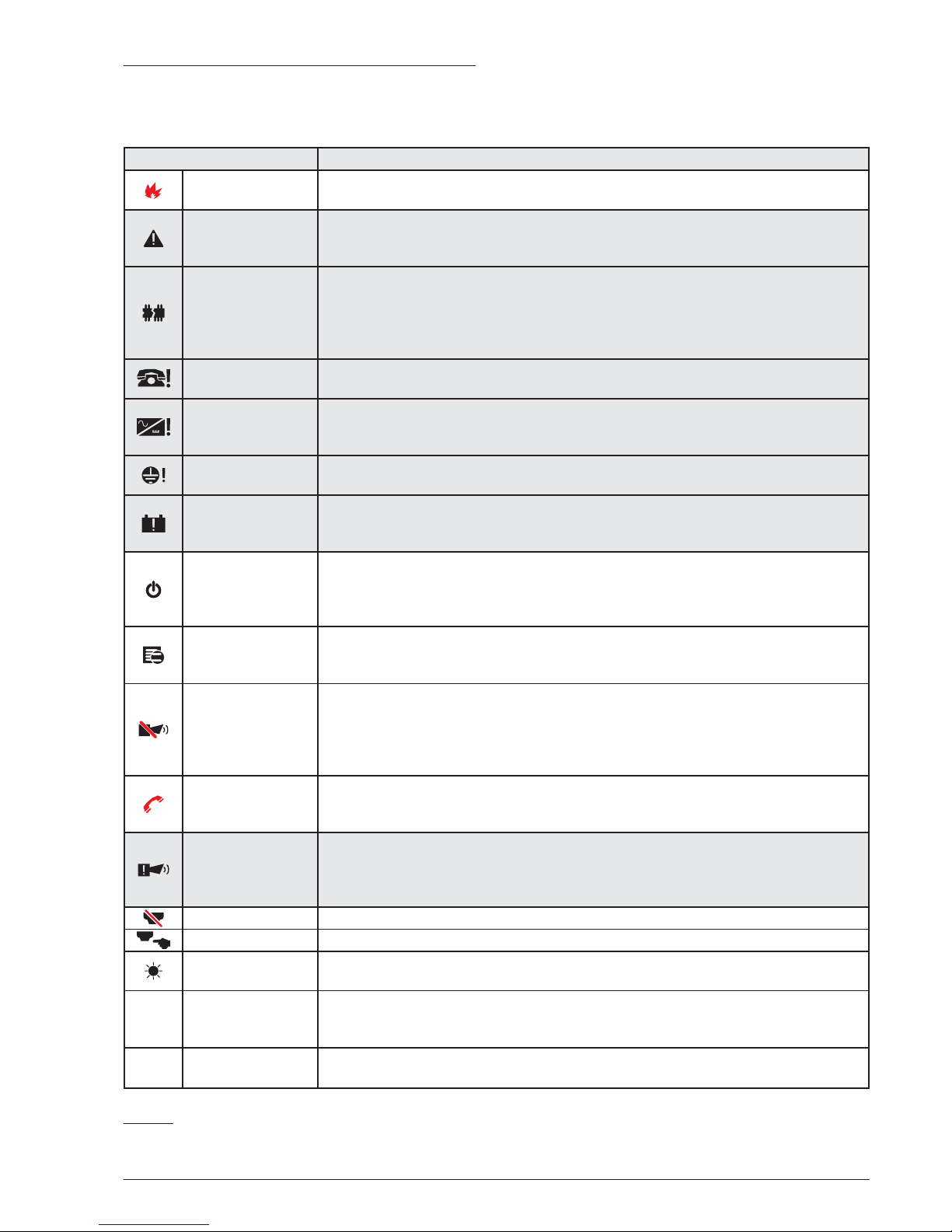
The status LED
Table 6 describes how the Control panel LEDs oper
-
ate. During standby status, ONLY the GREEN Mains
LED and the Day mode LED (if the control panel is in
Day mode) should be On (glowing) .
12 Addressable Fire Panel FC501
LED DESCRIPTION
FIRE
(Red)
Glowing indicates Alarm status. In the event of an Alarm, the Control panel activates
the unbypassed alarm outputs.
GENERAL FAULT
(Amber)
Glowing indicates the presence of a Fault. The following LEDs or the screen on the di
splay indicates the type of Fault.
Slow blinking indicates a fault event in memory (Reset turns OFF ).
SYSTEM FAULT
(Amber)
Glowing indicates a blocked Control Panel. IMPORTANT: Maintenance required.
Slow blinking indicates the Control Panel restart.
Fast blinking indicates that the data panel programming is corrupted.
NOTE – When the Control panel is switched on for the first time, this LED blinks until a
Reset has been performed.
FIRE SIGNAL
FAULT (Amber)
Glowing indicates the communicator has been disabled.
Slow blinking indicates that the communicator has broken down.
POWER SUPPLY
FAULT (Amber)
Glowing indicates Mains failure (110/230 V).
Fast blinking indicates Switching Power supply fault.
During this condition,the Control panel will be powered by the batteries.
EARTH FAULT
(Amber)
Glowing indicates a Voltage leakage to Earth.
IMPORTANT: Check wiring insulation.
BATTERY
TROUBLE
(Amber)
Glowing indicates that the batteries empty or faulty. If this condition persists, the bat
teries will be unable to function as intended in the event of blackout.
IMPORTANT: New batteries are required.
POWER ON
(Green)
Glowing indicates that the panel is supplied with power.
OFF indicates Mains failure (both mains & battery power is lost) (Battery disconnect
threshold: 19,2 V). Power must be restored before the batteries reach the disconnect
threshold.
MORE INFO
(Amber)
Glowing indicates that there is hidden information with lower priority. Access the
page View List to show the hidden information.
OFF indicates No hidden information is available.
SOUNDERS
SILENCED
(Amber)
Glowing indicates that the Silenceable outputs and Loop device have been forced to
standby by means of theSILENCE/RESOUND SOUNDERS key.In Day Mode, the Si
lence status will be held until the SILENCE/RESOUND SOUNDER key is pressed
again. In Night Mode, the Silence status will be held until the Night mode Silence time
expires or until a new Alarm/Trouble condition is detected.
FIRE SIGNAL ON
(Red)
Glowing indicates that the transmission was successful. Slow Blinking indicates that
the transmission is in progress. On the control panel screen, the connection type:
PSTN, GSM, or LAN network are displayed.
SOUNDERS
FAULTS/DIS
Glowing indicates that the SC1 Output is disabled or outputs configured to "act as
SC1" are disabled. Slow blinking indicates that the SC1 is in fault or outputs configu
red to "act as SC1" are in fault. OFF indicates all the main sounder outputs (EN54-1,
TYPE "C" outputs) function properly.
DISABLED Glowing indicates the Disabled status of any bypassable entity.
TEST Glowing indicates Test conditions on at least one zone.
DAY MODE Glowing indicates that the Control panel is operating in DAY MODE.
OFF indicates that the Control panel is operating in NIGHT MODE.
1- 8 SOFTWARE ZONES
RED
Glowing indicates that the corresponding Software zones are in Alarm status.
Slow Blinking indicates that the corresponding Software zones are in Delay to Alarm
status.
N/D CONTROLS ON
(AMBER)
Glowing indicates that the Control Panel is at least at level 2 so the Silence/Reso
und Sounders, Reset and Investigation Delay Keys are enabled.
Table 6 Description of the status LEDs.
Page 13
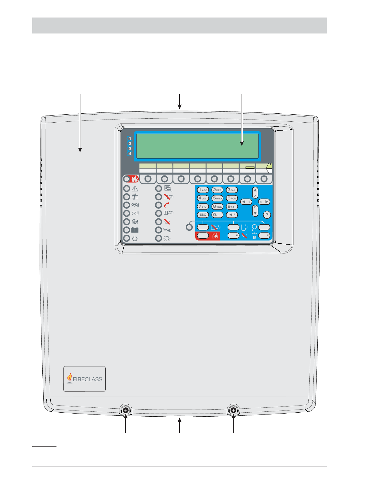
PARTS IDENTIFICATION
PARTS IDENTIFICATION 13
FIRE
FAULT
-
LE LI
NC NOCNC NO
C
J1
+NAC1
+NAC2
MICSPK BLKRED OC1 Oc2
24R 24A
RS485
+
-
24V
BAT
-
+
PSU
PC LINK
ADD ON
SH
+ LEFT - +RIGHT-
LOOP1
SH
+ LEFT - +RIGHT-
LOOP2
SH
+ LEFT - +RIGHT-
LOOP3
B078-P0
LCD
J5
ABC
JKL
STU
ESC
DEF
MNO
VWX
GHI
PQR
YZ
1
4
7
2
5
8
0
3
6
9
?
A
D
BC
EF
]
ABC
JKL
STU
ESC
DEF
MNO
VWX
GHI
PQR
YZ
1
4
7
2
5
8
0
3
6
9
?
A
D
BC
EF
]
FIRECLASS FC501
MSACMNE0FC501IC0.0
MSACMNE0FC501IC0.0
FC501
123
454
Figure 1 FC501 Parts: external view.
Page 14
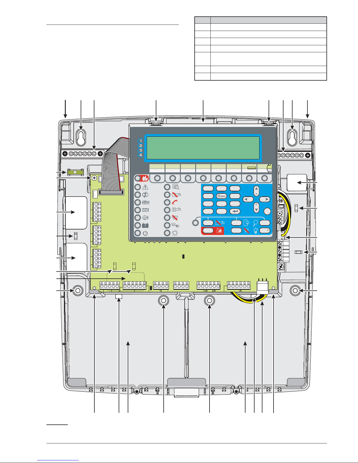
Description of Parts
This section describes the components of the FC501
Control panels.
Unless otherwise stated, the numbers in boldface in this
Manual refer to the tables and diagrams in this section.
P. Description
1 FC501 cover
2 Knockouts for cables ducted externally
3 Display
4 Screws (2) to close the Cover on Backplate
5 Knockout for connection FC501-H Panel with
FC500BX battery cabinet (accessory item)
6 Hooks to secure the cover on the backplate
7 Backplate anchor screw locations
14 Addressable Fire Panel FC501
AC/N
FG
+V
GND
B+
L
B–
GND
+V
AC/L
F 2A/25ØV
F6.3A/25ØV
FIRE
FAULT
-
LE LI
NC NOCNC NO
C
J1
+SC1
+SC2
MICSPK BLKRED OC1 Oc2
24R 24A
RS485
+
-
24V
BAT
-
+
PSU
PC LINK
ADD ON
SH
+ LEFT - +RIGHT-
LOOP1
SH
+ LEFT - +RIGHT-
LOOP2
SH
+ LEFT - +RIGHT-
LOOP3
B078-P0
LCD
J5
ABC
JKL
STU
ESC
DEF
MNO
VWX
GHI
PQR
YZ
1
4
7
2
5
8
0
3
6
9
?
A
D
BC
EF
]
ABC
JKL
STU
ESC
DEF
MNO
VWX
GHI
PQR
YZ
1
4
7
2
5
8
0
3
6
9
?
A
D
BC
EF
]
FIRECLASS FC501
MSACMNE0FC501IC0.0
MSACMNE0FC501IC0.0
14
678 9 10 9876
11
12
13
12
14
151617181919181715
20
21
20
22
23
20
21
Figure 2 FC501 Parts: external view.
Page 15
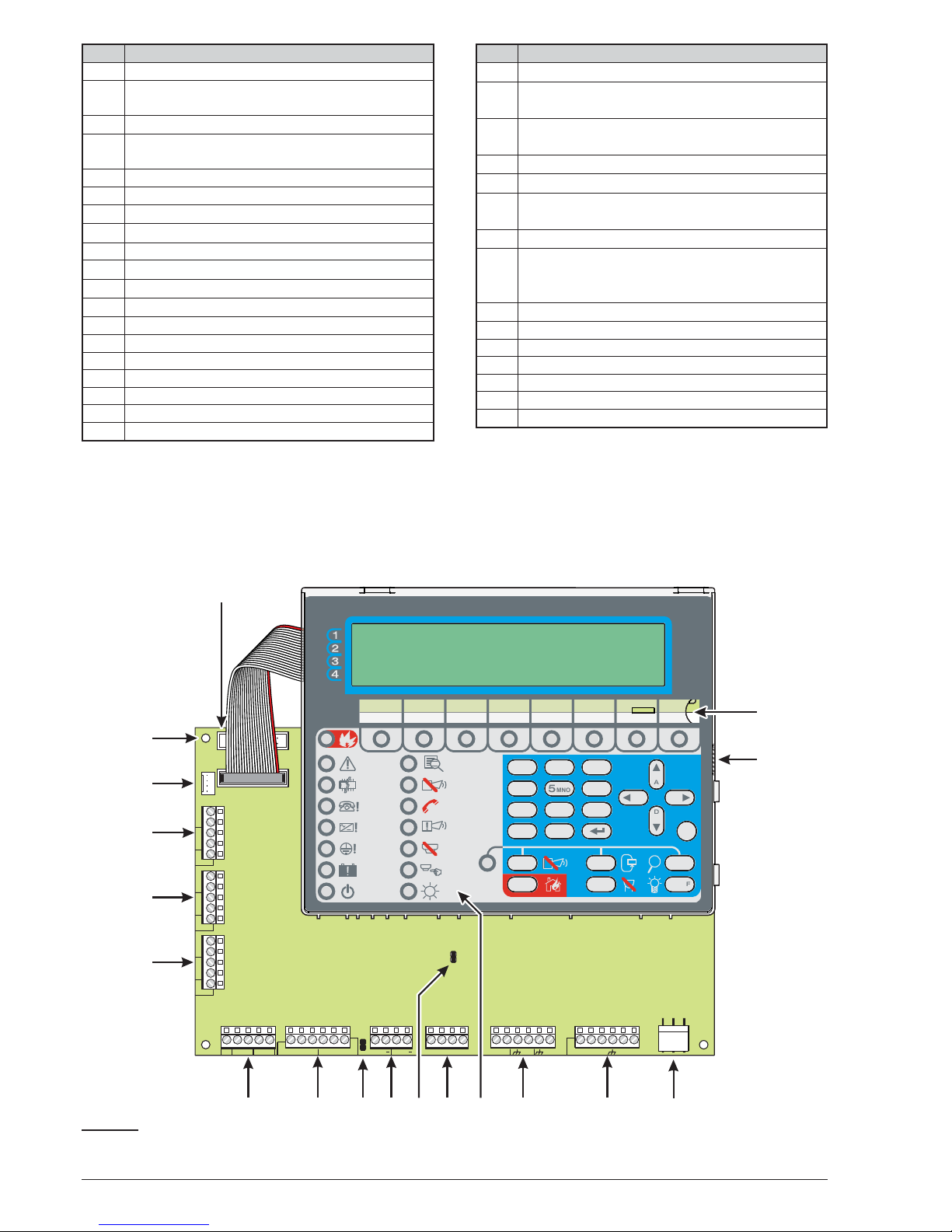
P. Description
8 Terminals (2) for the earth connection wires
9 Hooks (2) to secure Main module on the
backplate
10 Main Module (see figure 3)
11 Cable entry for channeled undertrack cables:
power cable
12 Anchors (2) for power cable
13 Switching power supply (see figure 4)
14 Backplate anchor screw locations
15 Main module supports (2)
16 Power cable for Main module
17 Opening (2) to secure batteries
18 Location for 2 batteries 12V, 7Ah or 12Ah
19 Backplate auxiliary anchor screw locations (2)
20 Cable entry (3) for channeled undertrack cables
21 Cables anchor (3)
22 Screw to secure main module
23 Tubular spirit level
24 Connector for FC500IP Module
25 Opening to insert the zone location text strip
26 USB port
P. Description
27 Power supply main module connector
28 RS485 Serial port & battery connection termi
-
nals
29 Programmable outputs and auxiliary power
supply terminals
30 Buzzer (not visible)
31 Terminals for future use
32 Jumper J5 to reset the installer PIN n. 1 to the
factory default (00000)
33 SC outputs
34 Jumper for the exclusion of the Earth Fault:
// = Earth Fault detected (Default);
oo = Earth Fault ignored
35 FIRE and FAULT relay outputs
36 Terminals for phone line connection
37 Loop1
38 Loop2
39 Loop3
40 RS232 Serial (PC link)
41 Hole for Main module fixing
SPECIFICATIONS 15
FIRE
FAULT
-
LE LI
NC NOCNC NO
C
J1
+SC1
+SC2
MICSPK BLKRED OC1 Oc2
24R 24A
RS485
+
-
24V
BAT
-
+
PSU
PC LINK
ADD ON
SH
+ LEFT - +RIGHT-
LOOP1
SH
+ LEFT - +RIGHT-
LOOP2
SH
+ LEFT - +RIGHT-
LOOP3
B078-P0
LCD
J5
ABC
JKL
STU
ESC
DEF
MNO
VWX
GHI
PQR
YZ
1
4
7
2
5
8
0
3
6
9
?
A
D
BC
EF
]
ABC
JKL
STU
ESC
DEF
MNO
VWX
GHI
PQR
YZ
1
4
7
2
5
8
0
3
6
9
?
A
D
BC
EF
]
FIRECLASS FC501
MSACMNE0FC501IC 0.0
MSACMNE0FC501IC 0.0
36 35 34 33 32 31 30 29 28 27
26
25
41
40
39
38
37
24
Figure 3 Main module Parts.
Page 16
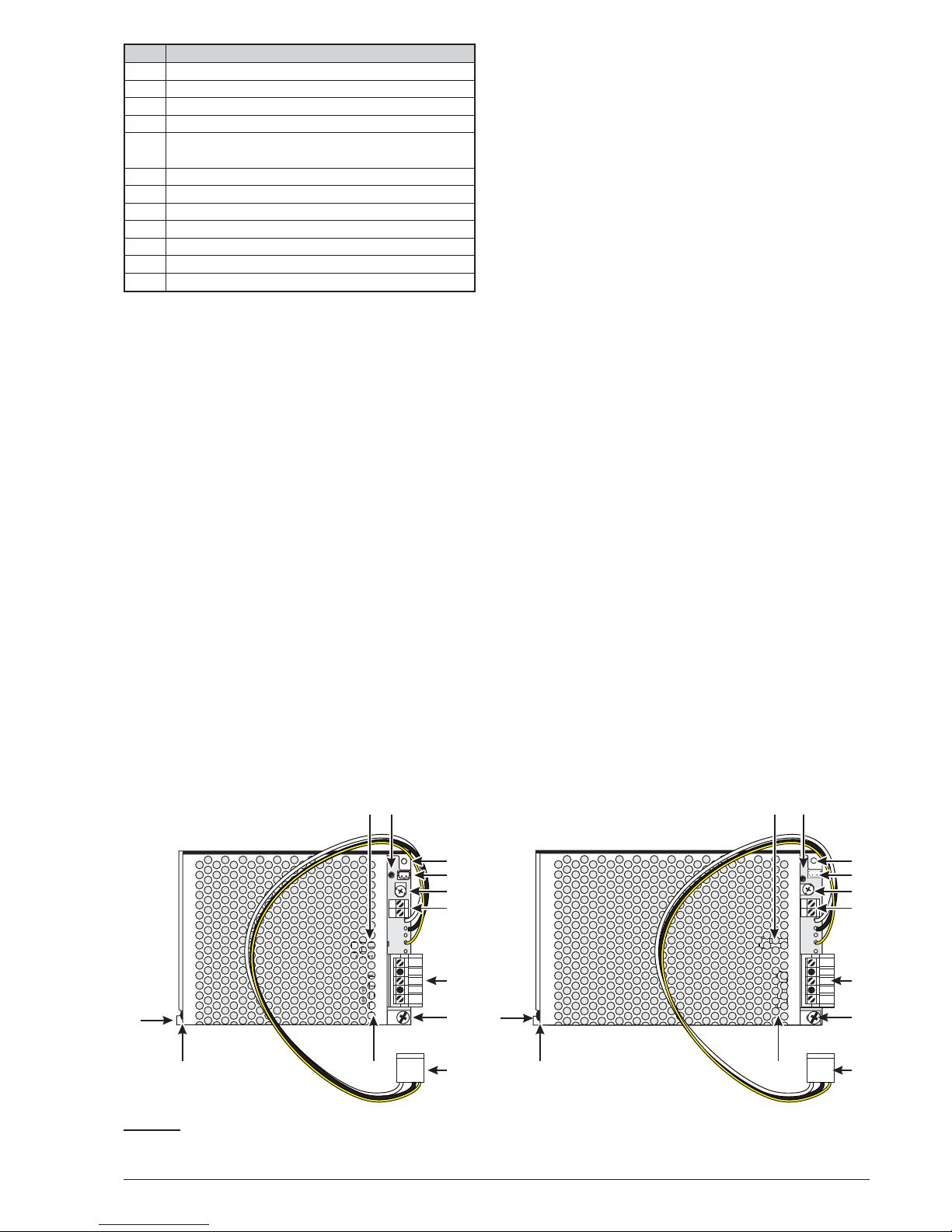
P. Description
42 Protection Fuse
43 Main Power LED
44 Hole for switching Power supply fixing
45 Thermal probe connector
46 Fine trimmer for the Switching-power-supply
output Voltage
47 Auxiliary power-supply terminals (27.6 V_)
48 Mains power terminals (110/230V~60/50 Hz)
49 Switching-power-supply fixing screw
50 Cable for connecting Main Module
51 Protection Fuse
52 Switching-power-supply closure plastic rivet
53 Switching-power-supply anchor
* NOTE (1)
Before connecting the Fire control panel to PC for the
PC programming phase, remove the jumper 34 of main
board. When the programming phase is finished, re
place the jumper otherwise the Earth fault (Leakage to
Earth) will not be detected.
* NOTE (2)
To silence the buzzer permanently during installation,
engage the control panel at Access Level 3 and remove
the Jumper J5 32. If the buzzer is disabled, the panel
User Interface does the following: the zonal LEDs
slowly flash and "BUZZER OFF" string is displayed al
ternately with date and time. The timeout for the in
staller access is not changed as a result of this
procedure. To reactivate the buzzer, replace the
Jumper J5 when the installation process is complete.
16 Addressable Fire Panel FC501
AC/N
FG
+V
GND
B+
L
B–
GND
+V
AC/L
F 2A/25ØV
F6.3A/25ØV
B+
L
B–
GND
+V
F6.3A/25ØV
F 2A/25ØV
BAW50T24
42 43
44
45
46
47
48
49
50
52
53
51
BAW75T24
42 43
44
45
46
47
48
49
50
52
53
51
Figure 4 BAW50T24 and BAW75T24 Switching-power-supply.
Page 17

INSTALLATION
!
Installation of this system must be carried out
strictly in accordance with the instructions in
this section, and in compliance with the local
safety regulations in force.
Prior to commencing the installation of the control
panel, ensure that adequate precautions are taken to
prevent damage to the sensitive electronic components
on the display board and the control board due to elec
trostatic discharge. You should discharge any static
electricity you may have accumulated by touching a
convenient earthed object such as an unpainted copper
radiator pipe. You should repeat the process at regular
intervals during the installation process.
To install the fire panel, follow these steps:
Ø
choose suitable mounting locations for the Control
panel, detectors, fire warning and fire control devices.
+
The panel must be located in a clean, dry position,
which is not subject to shock or vibration and at
least 2 metres away from pager systems or any
other radio transmitting equipment.
Ø Lay the cables between the Control panel and the
system peripherals.
+
Fire alarm cables must be separated from all other
wiring that is not related to the fire alarm system.
Ø
If necessary, install any accessory modules.
Ø
Carry out the necessary connections, leaving the
power-supply connection until last.
Ø
Program the Control panel in accordance with the in
-
structions in the “PROGRAMMING” section.
Ø
Test the entire system (Control panel, detectors, fire
warning and fire control devices).
+
FC500IP module (Accessory Modules) should be
installed before mounting the Control panel as de
-
scribed in the paragraph: FC500IP module Instal
-
lation.
!
Ensure that the Control panel power supply
(Mains and Batteries) has been disconnected
before installing any accessory Modules.
Installing the Control panel
Work carefully through the following steps (see the Fi
-
gures 1 and 2).
1. Remove the screws (4) and open the Control panel.
2. Drill the anchor screw holes 7 and 14.
+
Check for water pipes and electrical wiring before
drilling.
+
When using 12Ah batteries use mounting holes 19
to provide additional support.
+
Use the Tubular spirit level (23) for leveling the Pa
-
nel backplate.
!
Check for water pipes and electrical wiring before drilling.
3. If necessary, remove the surface conduit wire
knockouts 2.
+
The cable conduit union with the cabinet must be
secured by HB Flame Class (or higher) lock nuts.
4. Pull the channeled undertrack cables through the
cable entry 11 and 20 (for the power supply cable)
then, using the anchor screws locations, secure the
backplate to the wall.
+
Use anchors 12, (for the power supply cable) and
21 to secure the cables through the cable ties.
n
Control panel closure
To close the panel:
1. Attach the cover to the hooks (6) and then rotate the
cover down.
2. Use the screws (4) to secure the cover on the
backplate.
INSTALLATION 17
Page 18
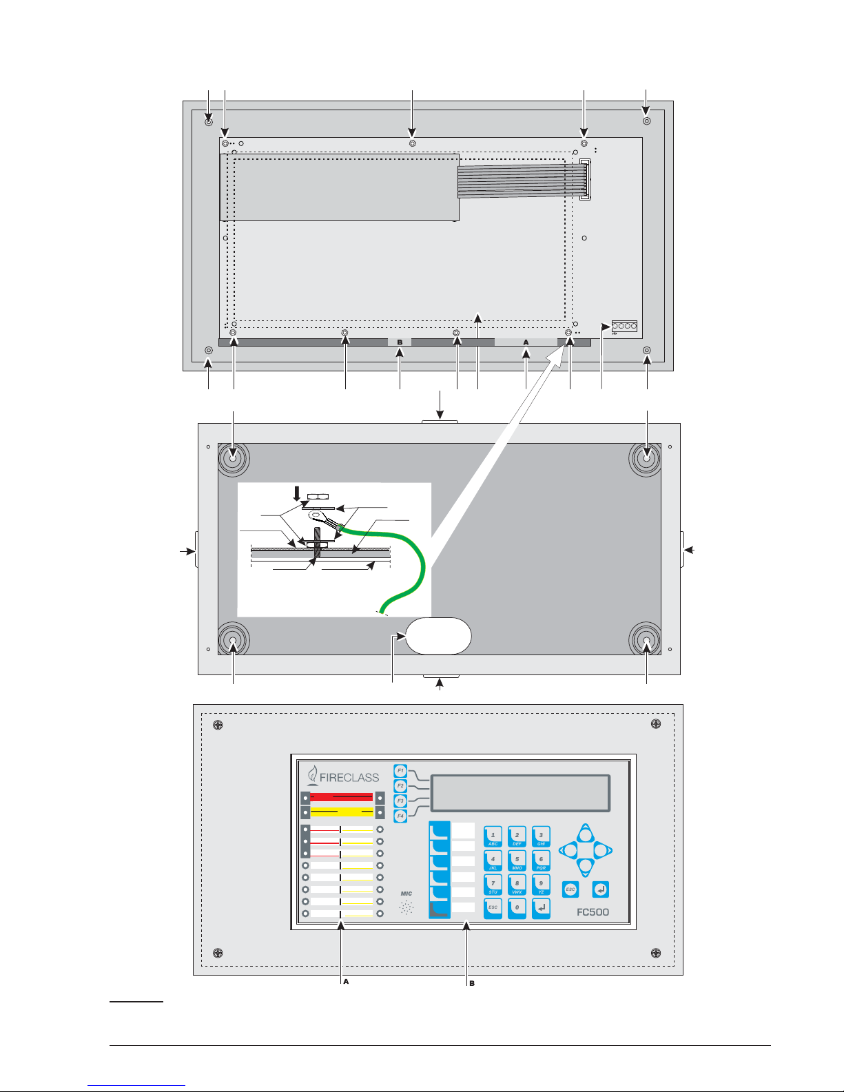
18 Addressable Fire Panel FC501
68
68 68
68
65
65
65
70 73
66
66
66
66
+
-
RS485
24V
67
69 69 69
69 69 69 69a
72
71
65
Repeater earth connection (nut 69a)
LEDS AND KEYS LABELS
To insert the LED and Keys Labels (supplied) in the Repeater User Interface (see Figure below) work through the following steps:
1) Remove the screws 68 and open the Repeater FC500REP. Corresponding the A or B (in the overlay) insert the relevant LED and KEYS Labels.
3) Check that the labels are correctly inserted and then close the Repeater FC500REP.
Repeater PCB
Nut M3
Support
Earth connection
Repeater Cover
Plastic Frame
Washer
ESC
ABC DEF GHI
JKL MNO PQR
STU VWX YZ
1
4
7
2
5
8
0
3
6
9
ESC
F1
F2
F3
F4
MIC
FC500
LAMP
BUZZ
TEST
SILENCE
INVESTIGATE
SILENCE
BUZZER
RESET
EVACUATE
MORE ALARMS
LOGIC UNIT
PRE-ALARM
LOST DEVICE
COMMUNICATOR
DAYMODE
NAC FIRE OUTPUT
DISABLED
HEARTH
SILENCE
LOW BATTERY
TEST
NO BATTERY
MAINS
FIRE
FAULT
COMMUNICATOR
MAINS
Figure 5 Installation FC500REP Repeater.
Page 19
Installing FC500REP Repeater
Repeaters can be wall mounted, or flush mounted to an
ave
®
BL08 outlet box (or similar).
Follow these steps when installing an FC500REP Re
-
peater:
1. Lay the connection cables (refer to “Connecting
Repeaters”).
2. Remove the screws (68) (see Figure 5) and open
the Repeater FC500REP.
3. If you are flush mounting the Repeater, go to step
4. If you are wall mounting the Repeater, drill the
anchor screw holes (66).
4. Pull the wires through the wire entry (67), then, us
ing the anchor screws, secure the Repeater to the
wall.
5. Complete the connections to the terminal board 73
of the RS485 Interface, as described in the “Con
-
necting Repeaters” section.
- Connect the earth wire to the threaded support
69a on the cover, as illustrated in Figure 5.
P. Description
65 Knockouts for cables ducted externally
66 Holes for cabinet mounting
67 Cable entry for channeled undertrack cables
68 Screws to secure cover
69 Fixing nuts for User Interface on Cover
69
a
Repeater nuts for earth connection
70 User interface Repeater board
71 LED label slot
72 Key label slot
73 Connector for the Repeater RS485 interface
Description of the Terminals
This section describes the Control panel terminals.
n
Loop
LOOP1 Loop 1 terminals:
Ø
+LEFT: Positive signal
Ø
- LEFT: Negative signal (return).
Ø
+RIGHT: Positive signal
Ø
-RIGHT: Negative signal (return).
Ø
-SH: Cable shield terminal.
LOOP2 Loop 2 terminals (as Loop1)
LOOP3 Loop 3 terminals (as Loop1)
+
The three loops of the panel can manage up to 128
addressable devices.
+
The total length of the cables connected to the
three loops must NOT exceed 2000 m.
+
The max current load for the three loops must not
exceed 500 mA +25%.
n Telephone line
LE Terminals for connecting the external telephone
line.
LI Terminals for connecting the internal telephone line:
connect these terminals to other telephone devices that
need to share the same phone line as the fire panel.
-
Terminal for connecting the earth wire.
n
Fire
[NC][NO][C]
Non-supervised fire output. Dry contact
relay for non-supervised devices.
It is activated, by default, at the entering of the panel in
to the alarm status (first fire event).
The de-activation of the fire output is executed during
the panel reset.
The fire output may be silenced (programmable option;
default=NOT silenceable).
The fire output may be disabled.
The fire output may be programmed to works differently
(only via FCConsole Software).
Ø
During standby status, terminal [C] closes to terminal
[NC];
In the event of fire, terminal [C] closes to terminal [NO].
+
EN54-2 certification applies ONLY when FIRE output
is not C and/or J and/or G (EN 54-1) type. Therefore
this output MUST NOT BE UTILIZED to manage Fire
Alarm devices and/or Fire/Fault transmission devices
and/or Automatic Fire alarm system.
INSTALLATION 19
Page 20

n
Fault
[NC][NO][C]
Non-supervised Fault output. Dry con
tact relay for non-supervised devices.
It is activated at:
Ø
the entering of the panel in to the fault status (first fault
event).
Ø
in the case of Logic fault
Ø
in the case of total loose of the power.
The de-activation of the fault output is executed during
the panel reset.
The fault output may not be silenced.
The fault output may not be disabled.
The fault output may not be programmed to works diffe
-
rently.
Ø
During standby status, terminal [C] closes to terminal
[NC];
Ø
In the event of fault, terminal [C] closes to terminal
[NO].
+
EN54-2 certification applies ONLY when FAULT
output is not J (EN 54-1) type. Therefore this output
MUST NOT BE UTILIZED to manage Fault tran
-
smission devices.
SC1 (Sounder Circuit)
Supervised/Silencea
-
ble/Bypassable (Disabled) Bell output, for the Alarm
signalling devices. Terminals for the connection of devices that are activated with the positive (24V) and must
be supervised.
During standby status: negative pull-down to 0 V on [+]
terminal; positive pull-up to 27.6 V on the [–] terminal.
When control panel is in alarm status: positive pull-up to
27.6 V on the [+] terminal; negative pull-down to 0 V on
the [–] terminal.
SC1 can be Silenced (forced to standby) by the menu
command DISABLE.
+
This output is not programmable, it is activated every
time the control panel goes into ALARM status.
SC2 (Sounder Circuit Supervised/Silencea
-
ble/Bypassable (Disabled), Programmable Bell out
put, for the Panel Alarm signalling or Panel Delay to
Alarm or Panel Warning or Panel Fault or 1,2,3 or 4
Software zones(OR) Alarm, or 1,2,3 or 4 Software zo
nes(OR) Delay to Alarm, or 1,2,3 or 4 Software zo
nes(OR) Warning or 1,2,3 or 4 Software zones(OR)
Fault or 1,2 or 3 Points(OR) Alarm or 1,2 or 3 Po
ints(OR) Delay to Alarm or 1,2 or 3 Points(OR) War
ning or 1,2 or 3 Points(OR) Fault.
During standby status: negative pull-down to 0 V on [+]
terminal; positive pull-up to 27.6 V on the [–] terminal.
When a programmed event occurs: positive pull-up to
27.6 V on the [+] terminal; negative pull-down to 0 V on
the [–] terminal.
+
The SC1 and SC2 outputs can be forced to
standby by resetting the control panel.
The SC Outputs will hold standby status for the pro
grammed Silence Time. If Alarm conditions are present
when the programmed Silence Time expires for the
SC1 or another programmed event for the SC2, they
will re-activate.
+
SC1, SC2 accept devices that operate within SELV
limits ONLY.
+
The SC2 output, if programmed as SC1, will be of
type C.
+
If the 2-wire connection loop is used, the EN54-2
certification applies ONLY when the total number
of devices (detectors, manual callpoints etc.) does
not exceed 32.
n
Audio station
MIC|SPK|BLK|RED Terminals for future use.
n
Auxiliary outputs
OC1-OC2 Silenceable, Bypassable (Disabled), NOT
Supervised Outputs, programmable
. These are
open-collector terminals for the Panel Alarm signalling
(Default) or Panel Delay to Alarm or Panel Warning or
Panel Fault or 1,2,3 or 4 Software zones(OR) Alarm, or
1,2,3 or 4 Software zones(OR) Delay to Alarm, or 1,2,3
or 4 Software zones(OR) Warning or 1,2,3 or 4 Software zones(OR) Fault or 1,2 or 3 Points(OR) Alarm or 1,2
or 3 Points(OR) Delay to Alarm or 1,2 or 3 Points(OR)
Warning or 1,2 or 3 Points(OR) Fault, which will be close to ground, when the connected event becomes active, and will remain in this state until the generating
event has ended (so after a manual reset or a fault restore)
.
+
The output OC1 can also be programmed to signal
the failure of the telephone line so as to be used in
combination with a relay, for switching from the pri
-
mary phone line to the reserve line.
The OC1 and OC2 outputs can be forced to standby by
resetting the control panel.
The OC1 and OC2 outputs will activate with a delay
equal to the Delay to Alarm time when the programmed
event occurs.
+
EN54-2 certification applies ONLY when OC1 and
OC2 outputs are not C and /or J and/or G (EN 54-1)
type. Therefore this output MUST NOT UTILIZED
to manage Fire Alarm device and/or Fire/Fault
transmission devices and/or Automatic Fire alarm
system.
24R [M]
Reset able auxiliary power supply to devices
that operate at 24 V (0.5A max) (powered by the
standby batteries):
ØPositive (27.6 V) on terminal [24R];
ØNegative on terminal [M].
20 Addressable Fire Panel FC501
Page 21

+
This power supply is disconnected during the reset
of the Control Panel (about 2 seconds) so it is sui
table for devices that are restored when power
supply is disconnected.
24A [M]
Auxiliary Power supply to devices that ope
-
rate at 24 V (0.5A max) always present and guaranteed
by the batteries:
Ø Positive (27.6 V) on terminal [24A];
Ø
Negative on terminal [M].
n
RS485
24V|–|+|M
Terminals for FC500REP repeater (maxi
-
mum 4) and FC500MFI module (maximum 4) (0.5A
max).
Ø
Serial bus terminals [+] and [-];
Ø
27.6 V power voltage terminals [M] and [24V].
+
The maximum cable run allowed is 1000m.
n
Battery
+BAT- Terminals to connect the batteries inside the
FC501 control panel.
The System Wiring
!
High Voltage leads (110/230 V) must be bunched
separately from Low Voltage leads (24 V). All
leads must be bunched in such a way as to avoid
contact with other wiring and components.
n
Connecting Addressable Devices
The control panel has 3 loops for addressable analogue
devices.
The maximum for all 3 loops is 128 addressable analo
-
gue fire detectors and analogue devices (Input modu
-
les, Output modules).
+
Every detector and module connected to the loops
must be assigned a unique address.
You can use 2 or 4 wires for the loop connections.
NOTE: The loop connection type must be specified du
ring the programming phase.
Figure 7 illustrates the 2-wire connection to Loop1.
Figure 6 illustrates the 4-wire connection to Loop2.
+
Whatever the type of connection performed, make
sure that any short circuit or open circuit in the wi
-
ring does not lead to the loss of more than 32 de
-
tectors. An isolator should be fitted at least every
32 detectors.
+
If the connection is a 2-wire connection type, addressable analogue fire detectors and analogue
devices (Input modules, Output modules)connect
on the left.
+
Use only shielded cable for all connections, with
one end of the shield connected to the SH terminal
of the Control panel and the other left free.
INSTALLATION 21
Page 22
n
Connecting Repeater FC500REP
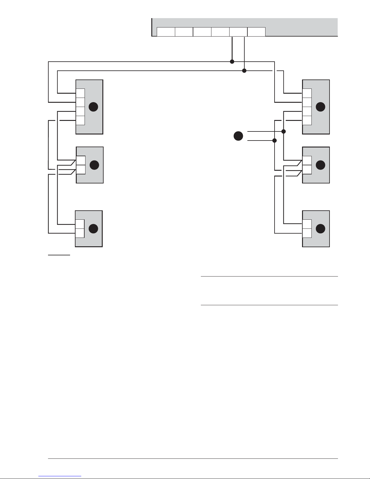
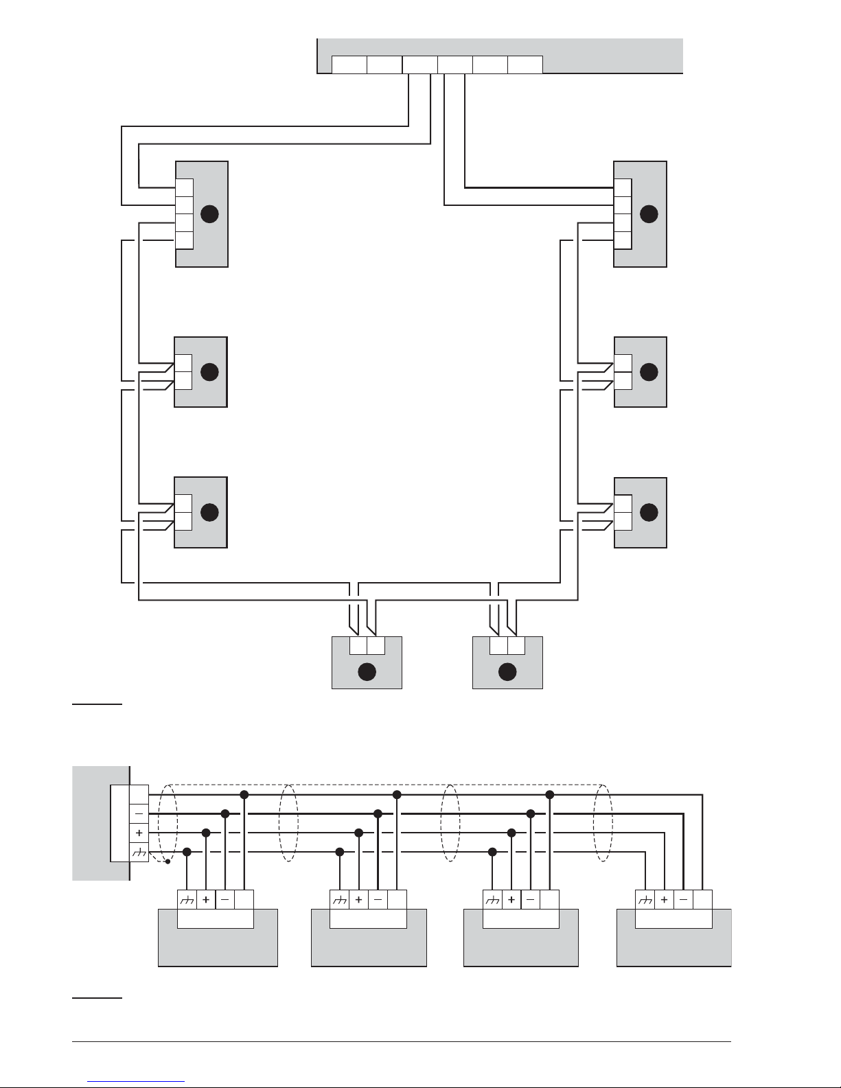
An example of how to connect two FC500REP repea
-
ters is displayed in Figure 8.
The RS485 port of the FC500 (terminals [M], [+], [-]
and [24V]) accepts up to 4 FC500REP repeaters;
Terminals [+] and [-] supply the power (27.6 V) to the re
peater panels (see figure 8).
When a mains fault occurs, the Repeaters considerably
decreases the absorbed power, switching off the LCD
display backlighting (the LCD display backlighting swit
ches on again, for 20 seconds when a key is pressed).
But the absorption of the Repeaters connected to the
control panel, will continue to run down the backup bat
teries, and decrease of the Stand-by supply time of the
system.
As one control panel only is in the system, all the Repe
aters must be supplied by the control panel itself, un
less a Power supply Station is in the system.
+
Use only shielded cable, with one end of the shield
connected to the earth terminal of the Control pa
nel and the other left free; the continuity, between
several segments of connection must be secured.
22 Addressable Fire Panel FC501
L-L-
L-
L-
L-
L-
L+L+
L+
L+
L+
L+
L-L-
L+L+
+L2-
A
C
BB
BB
A
FC501
+L2-+L1-+L1-
LEFT RIGHT LEFT RIGHT
+L3-+L3-
LEFT RIGHT
Figure 6 Wiring diagram of a 2-wire connection, a) Isolators; b) Compatible analogue devices (Fire detector, Input
modules, Output modules, Manual callpoints); c) T connection
.
Page 23
INSTALLATION 23
24V
RS485
24V
RS485
24V
RS485
24V
RS485
24V
RS485
FC501
FC500RepeaterFC500Repeater FC500Repeater FC500Repeater
Figure 8 Wiring diagram of four (max) (FC500REP) Repeaters connected to the RS485.
L-L-
L-
L-
L-
L-
L+L+
L+
L+
L+
L+
L-L-
L+L+
L- L-L+ L+
A
BB
B
B B
B
A
FC501
+L2-+L2-+L1-+L1-
LEFT RIGHT LEFT RIGHT
+L3-+L3-
LEFT RIGHT
Figure 7 Wiring diagram of a 4-wire connection: a) Isolators; b) Compatible analogue devices (Fire detector, Input
modules, Output modules, Manual callpoints)
.
Page 24
n
Connecting Output Devices
The control panel has NON supervised outputs and 2
Bell outputs.
Output devices can be connected to the loops by me
-
ans of Output modules.
n
Bell Outputs
The Bell outputs are indicated by the letter SC and their
address number.
+
The SC1, and SC2 Bell Outputs are Supervised,
Silenceable, Bypassable (Disabled) SC2 also Programmable.
The Bell outputs can be forced to standby status by the
SILENCE button. Once an alarm has been acknowled
-
ged, you can silence the audible signalling devices and
leave the visual signalling devices active until the alarm
conditions cease.
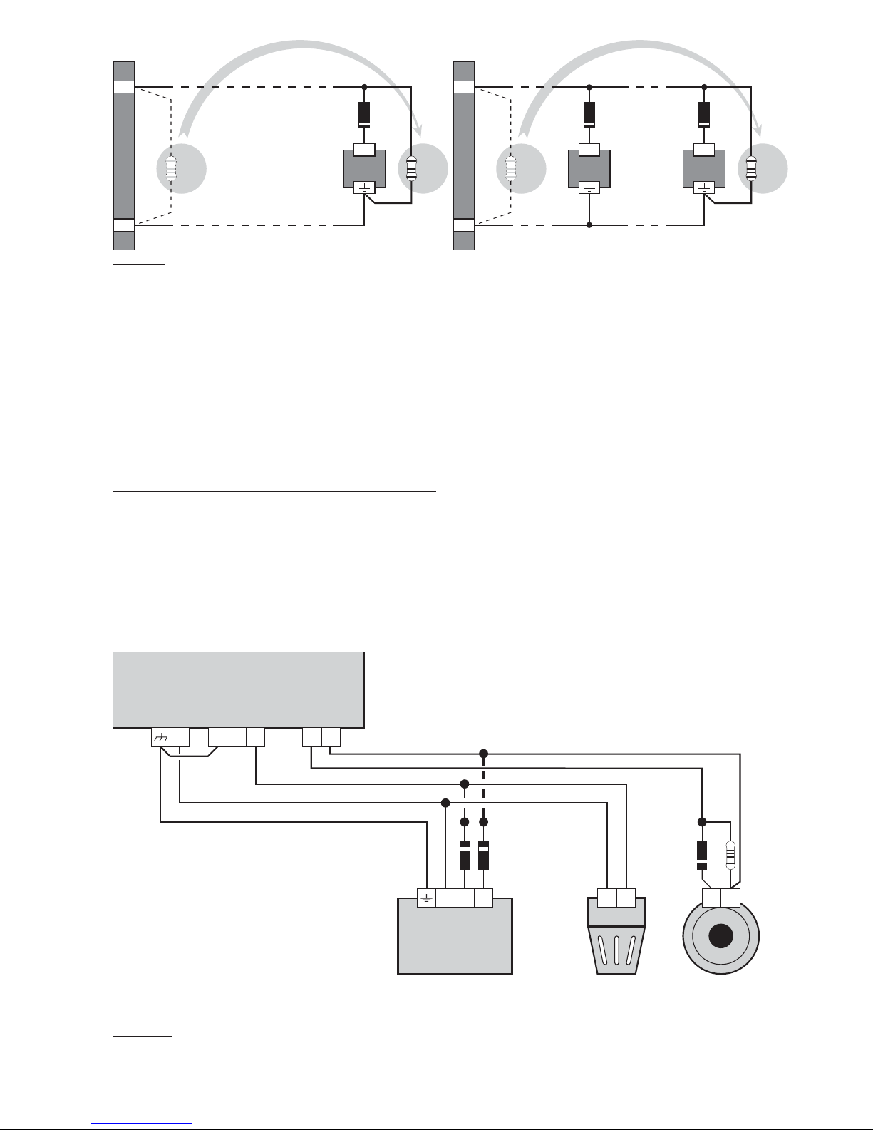
For example, a connection similar to the wiring diagram
in figure 10 will activate the Flasher, the Bell and the vi
-
sual and audible signalling device of the Self-powered
Siren in the event of an alarm.
Using the SILENCE button will stop the horn but not the
flasher, which will continue to signal Alarm status until
the RESET button is pressed.
24 Addressable Fire Panel FC501
+
-
A+ A+A+
(a) (b)
3k93k9 3k93k9
1N4002 1N40021N4002
SC 1
+
-
SC 1
Figure 9 Wiring diagram of the connection of a single device (a) and several devices (b) to Bell outputs (device acti
-
vated by positive (27.6 V) on terminal [A+]).
24A NC
NO
+
–
C
+N
–L –A
+–+–
SC1
1N4002 1N4002 2K7
Self-powered siren
CALL-R24
Flasher Bell
FC501
Figure 10 Wiring diagram: NON-silenceable and Silenceable Output connections.
Page 25
Connecting the Power Supply
+
The power circuits of this Control panel comply
with the EN54-4 standard.
!
In order to comply with the Safety regulations
in force, the Mains must be equipped with a bi
polar isolating device for protection against
over voltage and short-circuit to Earth (e.g. au
tomatic isolating switch).
This Control panel is powered from the Mains
(110/230V~ 60/50 Hz) through a switching power
supply, located inside the case. The FC501-L Control
panel provides housing for two 12V, 7Ah or 12Ah maxi
-
mum batteries; the FC501-H Control panel can be con
-
nected to two 12V, 12Ah or 38Ah in an external metal
box (see Figure 14) for power during Mains failure.
The non-volatile memory will hold the programmed data
at all times. In the event of MAIN failure, the AMBER Po
-
wer Supply LED will turn ON.
The Control panel will check the batteries at all times,
(refer to Static Test and Dynamic Test).
Static Test
The Static Test monitors the battery char
-
ge during Mains failure. In the event of Low battery status (below 22.8 V), the Low Battery LED will turn ON. If
this occurs, the Mains power must be restored before
the batteries empty, otherwise, the system will shutdown.
Dynamic Test
The Dynamic Test monitors the operating capacity of the batteries. In the event of a Failed
Test result (batteries do not meet the Test requirements), the No Battery LED will turn ON.
If this occurs, the backup battery must be replaced immediately, otherwise, the system will be unable to fun
-
ction in the event of Mains failure (blackout).
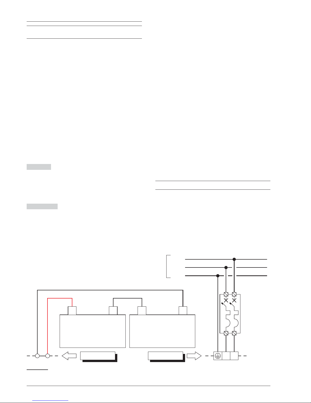
Follow these steps to connect the Mains Supply.
1. Locate the backup batteries in the housing (see
Figure 2). Secure the batteries to the backplate of
the panel, using the cable ties, in the appropriate
opening.
2. Using the Jumper supplied, connect the batteries in
series.
3. Observing the battery polarity, connect the battery
terminals to terminals -BAT+ on Main Board (wires
supplied).
4. FC501-L use 7 or 12Ah @ 12 V YUASA batteries;
FC501-H/FC501H-K use 12 or 38Ah @ 12 V
YUASA batteries or similar with case flame class
UL94-V2 (or higher).
5. Connect the switching power supply with the ‘exter
nal power supply (Main): connect the Earth wire to
the [Q] terminal on the mains terminal block 48.
6. Connect the Neutral wire to terminal [N], and the
Live wire to terminal [L] on the terminal board 48.
7. Connect the connector 50 to the main Board con
-
nector 16.
+
The Control panel will reset on power up.
!
DO NOT allow the power cable to cross over
other wiring (see Figure 2). The power cable
must be routed and held firmly in place by a two
cable tie.
INSTALLATION 25
L
Main Board
N
Automatic
isolating
switch
+
–
Battery 12 V
Live
Neutral
Earth
230 V
50 Hz
+
–
Battery 12 V
Power Supply
RED wire
BLACK wire
Jumper
Figure 11 Wiring diagram for the power supply.
Page 26

n
Thermal Probe
This Control panel supports the KST thermal probe.
The probe will optimize the battery charging process by
regulating the charge voltage in accordance with the
battery temperature.
Work carefully through the following instructions (refer
to figures 11 and 12:
1. Connect the probe 64 to the connector 45 on the
switching Power supply.
2. Attach the probe to one of the batteries, in such a
way as to obtain optimum heat transfer.
3. Measure the Probe temperature.
4. Using the graph in Figure 12 and/or Table 7, find
the value (in accordance with the battery tempera
ture) that the output voltage of the Switching Power
Supply will be based on.
5. Disconnect the batteries and turn on the panel.
6. Using the trimmer 46, adjust the voltage on the
voltage on the terminal board 47 to the required
value.
7. Connect the batteries to the main board
!
Before removing the probe, disconnect the bat
-
tery from the main board. Removing the ther
mal probe will cause the Switching Power
Supply output voltage to rise to 29V or greater.
This will overcharge or damage the battery.
Once the battery is disconnected and if it is re
quired to work without the thermal probe (EN54
approval will be lost),adjust the Switching
Power Supply output voltage, using the trim
mer 46, to 27.6Vdc. Reconnect the batteries
only if their voltage is equal to or less than
27.6Vdc.
+
To verify the battery efficiency, the charger circuit
will measure the internal resistance of the batte
ries. In order for this measure is not distorted, you
should use only the cables supplied; cables that
are longer and/or have an insufficient section may
erroneously simulate the condition of an inefficient
battery.
26 Addressable Fire Panel FC501
TEMPERATURE (°C) -10 -5 0 5 10 15 20 25 30 35 40 45 50
VOLTAGE (V) 29,0 28,8 28,6 28,2 28,0 27,8 27,6 27,2 27,0 26,8 26,6 26,4 26,2
Table 7 Switching Power Supply Output Voltage chart. To find the Output Voltage using the chart: — select the nea
-
rest value to the Probe temperature on the TEMPERATURE (°C) row; read the respective value on the VOLTAGE (V)
row; adjust the Output Voltage of the Switching Power Supply to the indicated value. For example, if the Probe tempe
-
rature is 22 °C, the Output Voltage of the Switching Power Supply must be set at 27.4 V.
-10-5 0 5 101520253035404550
26,0
27,0
28,0
29,0
VOLTAGE (V)
a)
27,4
22
Figure 12 Switching Power Supply Output Voltage graph. To find the Output Voltage using the graph: — indicate the Probe
temperature on the TEMPERATURE (°C) axis; draw a line from the temperature value point up to the curve a); draw a line from
the intersection point across to the VOLTAGE (V) axis; adjust the Output Voltage of the Switching Power Supply to the resultant
value. For example, if the Probe temperature is 22 °C, the Output Voltage of the Switching Power Supply must be set at 27.4 V.
Page 27
Installing FC500IP board
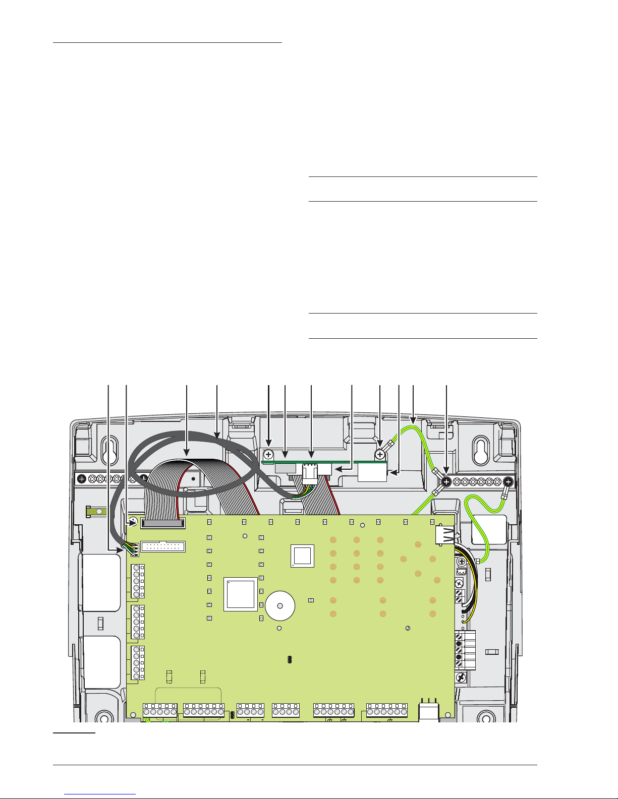
The IP Module should be installed into the base of the con
-
trol Panel, as illustrated in Figure 13. Follow these instruc
-
tions to install the FC500IP board:
!
Before installing the FC500IP Module, discon
nect control panel from its power supply
(mains and the batteries).
1. Open the control panel by unscrewing the two screws
4, then lift the cover from the bottom to separate it
from the backplate. Remove the fastening screw, fig
-
ure 2, item 22, between the motherboard and the
backplate and unlock the support of motherboard +
User Interface, figure 2, item 9, using a flat screw
-
driver. Lift the control board & display from the base.
2. Fix the IP Module on the base of the control panel
using the supplied screws 56.
!
The IP Module must be connected to the earth
of the electricity supply system.
3. Connect the cable 56a between the screws 56 and 56b.
!
The eyelet of the cable 56a must be inserted be
tween the fixing bracket of the module and the
screw 56.
!
Do not remove the wiring already present on
the screw 56b.
4. Connect the connector 58 of the IP Module to the
connector 55b of the control panel using the sup
plied flat cable 55. If you need to manage the control
panel ONLY/ALSO via IP, connect the connector
57a of the IP module to the connector 55a of the con
trol panel via the supplied PC-Link cable 55c.
5. Connect connector 59 to the LAN using an Ethernet
cable.
+
Use a category 5 (or better) shielded Ethernet ca
-
ble (STP or FTP).
6. Re-fit the control board & display and secure with
the screw.
7. Reconnect the control panel to the power supply.
8. Program the IP Module as described in the section
“PC Programming”. For further information, please
refer to the dedicated manuals.
+
See “To connect the control panel to a PC remo
-
tely”.
INSTALLATION 27
AC/N
FG
+V
GND
B+
L
B–
GND
+V
AC/L
F 2A/25ØV
F6.3A/25ØV
FIRE
FAULT
-
LE LI
NC NOCNC NO
C
J1
+SC1 +SC2
MICSPK BLKRED OC1 Oc2
24R 24A
RS485
+
-
24V
BAT
-
+
PSU
PC LINK
ADD ON
SH
+ LEFT - +RIGHT-
LOOP1
SH
+ LEFT - +RIGHT-
LOOP2
SH
+ LEFT - +RIGHT-
LOOP3
B078-P0
LCD
J5
55
58
56 56
59
55b 57 57a55a 55c 56a 56b
Figure 13 FC501 connection with the FC500IP.
Page 28

Installing the 38Ah battery metal Box
Work carefully through the following steps (see Figure 14),
for the FC501-H/FC501-HK fire panel only.
1. Remove the two screws on the cover and open the
metal box.
2. Drill the anchor screw holes 64.
!
Check for water pipes and electrical wiring be
-
fore drilling.
3. If necessary, using a hammer or similar tool, remove
the surface conduit wire knockouts of the metal Box.
4. Secure the metal base to the wall.
+
The cable conduit union with the cabinet must be
secured by HB Flame Class (or higher) lock nuts
(see particular in Figure 14).
5. Pull the wires through the cable entry and connect
them (see Figure 14).See paragraph: "Connecting
the power supply".
P. Description
54 Thermal probe (see Fig.11 and12)
55 Flat cable for the connection with FC500IP
55a Serial port RS 232 (PC LINK)
55b Module IP (FC500IP) connector
55c PC Link cable
56 FC500IP fixing screws
56a Cable for earth wiring of the FC500IP
57 FC500IP board
57a PC Link connector
58 Flat cable connector
59 Ethernet connector
60 38Ah Batteries cabinet (Accessory item)
61 Connecting Threaded tube
62 Nuts on Control Panel Backplate (FC501-H
and FC501-HK only)
63 Nuts on 38Ah Batteries Backplate (FC501-H
/FC501-HK)
64 Holes for cabinet mounting
Maintenance
To ensure that the system operates normally, it must be
maintained with regular testing by the user and periodic
maintenance by the installer in accordance with local
laws.
+
For the maintenance of other devices such as de
-
tectors, modules etc., follow the dedicated instruc
-
tions for the devices.
The following operations must be carried out regularly:
A Using a damp cloth (DO NOT USE SOLVENTS OF
ANY KIND), remove dust from the Control panel cabi
-
net.
B
Using the Lamp Test key, check that the LEDs and
buzzer are functioning properly.
C Ensure that the batteries are sufficiently charged and
functioning properly. If not, replace them immediately.
D Ensure that all cables and connections are intact.
E Ensure that there are no unrelated objects inside the
Control panel case.
F Ensure that the control panel is capable of processing a fire alarm and operating the relevant sounders
and/or outputs in consequence of this alarm. If there is a
facility for transmission of fire alarm signals to a Central
Station, ensure that the signal is correctly received.
G Verify the actual functionality of the circuit for the detection of earth fault. The procedure is as follows:connect one of the SH terminals of the loop to the ground:
Ø
verify that the fault is reported correctly by the Fire
Panel.
Ø
remove the connection previously made.
Points A and B may be carried out by users.
Points C, D, E, F and G must be carried out by qualified
persons only.
28 Addressable Fire Panel FC501
Page 29
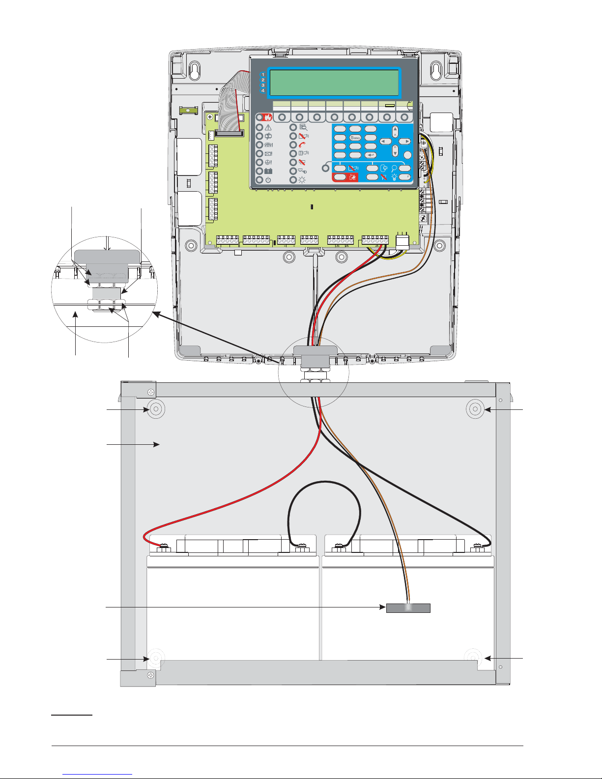
INSTALLATION 29
AC/N
FG
+V
GND
B+
L
B–
GND
+V
AC/L
F2A/25ØV
F6.3A/25ØV
FIRE
FAULT
-
LE LI
NC NOCNC NO
C
J1
+NAC1
+NAC2
MICSPKBLK RED OC1 Oc2
24R 24A
RS485
+
-
24V
BAT
-
+
PSU
PCLINK
ADDON
SH
+LEFT - +RIGHT-
LOOP1
SH
+LEFT - +RIGHT-
LOOP2
SH
+LEFT - +RIGHT-
LOOP3
B078-P0
LCD
J5
ABC
JKL
STU
ESC
DEF
MNO
VWX
GHI
PQR
YZ
1
4
7
2
5
8
0
3
6
9
?
A
D
BC
EF
]
ABC
JKL
STU
ESC
DEF
MNO
VWX
GHI
PQR
YZ
1
4
7
2
5
8
0
3
6
9
?
A
D
BC
EF
]
FIRECLASS FC501
MSACMNE0FC501IC0.0
MSACMNE0FC501IC0.0
62
61
63
60
54
60
64 64
64
64
Figure 14 Control Panel (FC501-H/FC501-HK) and 38Ah Batteries metal Box connection (accessory item).
Page 30

30 Addressable Fire Panel FC501
Page 31
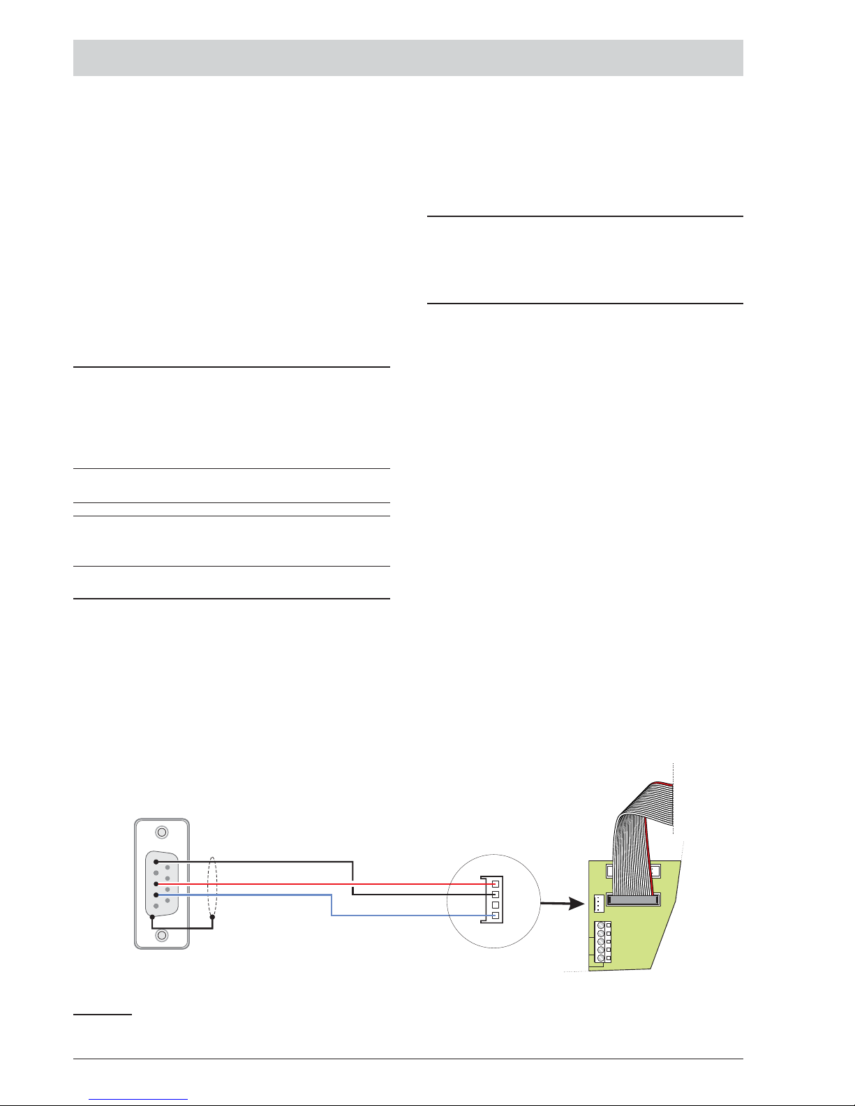
PC PROGRAMMING
The system can be programmed from the Control panel
(User Interface) or from a computer, using the FireClass
Console. This section describes how to program the
system from a computer. If you intend programming the
system from the Control panel refer to the
“PROGRAMMING FROM THE PANEL” section. To ma
nage and program the FC501 control panel using a PC, the
FireClass Console application must be installed on the
PC.
Installation
Complete the following steps to install the FireClass
console application:
Ø
Run the installer program FCConsole-v1.xx.x.x-Se
-
tup.exe (.xx.x.x indicates the program version).
Ø
Follow the required steps.
+
The latest version of the installer program can be
downloaded from the FireClass website.
+
When the FireClass Console starts for the first
time, it will prompt you to select a country. Select
and press the check button to confirm.
Select language
You can select the language of the FireClass Console
from the languages provided.
To Select the application language:
1. Run the FireClass Console application.
2. Select Tools from the Main window.
3. Select Language from the drop-down menu to open
a window with the language list.
4. Select a language from the Language list.
Software window Look
To modify the look of the FireClass Console window,
select Tools from the Main window and select “ Skin”.
This option allows you to modify the look of the window.
Control panel connections
When using the Supervisory, Management, Downloa
ding and Log Management functions, the control panel
must be connected to your PC in local communication
(RS232/USB) or remote by PSTN line, GPRS or LAN.
Ø
Connecting the control panel in local: connect the
PCLINK connector of the control panel (see Figure 3,
item 40) to a serial port of the PC using the PCLINK
cable (accessory item, see Figure 15) or use the
USB socket of the control Panel (see Figure 3 item
26) and a USB cable (Type A-A) or the USB cable
USB5M (508.032.037) (length 5 m.).
Ø To connect the control panel to PC remotely: install
the FC500IP board, as described in the paragraph
"Installing FC500IP board".
If the control panel is not connected to your PC, the
warning “Response from Panel Timed!” will display. If
the serial port for the local communication is invalid, the
warning “Cannot open serial port” will be shown.
PC PROGRAMMING 31
RS-232 Female Connector
Solder Side
1
4
5
2
3
PC-LINK Cable
4way
MTA Connector
PC LINK
ADD ON
SH
+ LEFT - +RIGHT-
LOOP1
LCD
Fire panel
Board
Figure 15 Schematic diagram of the PCLink cable.
Page 32
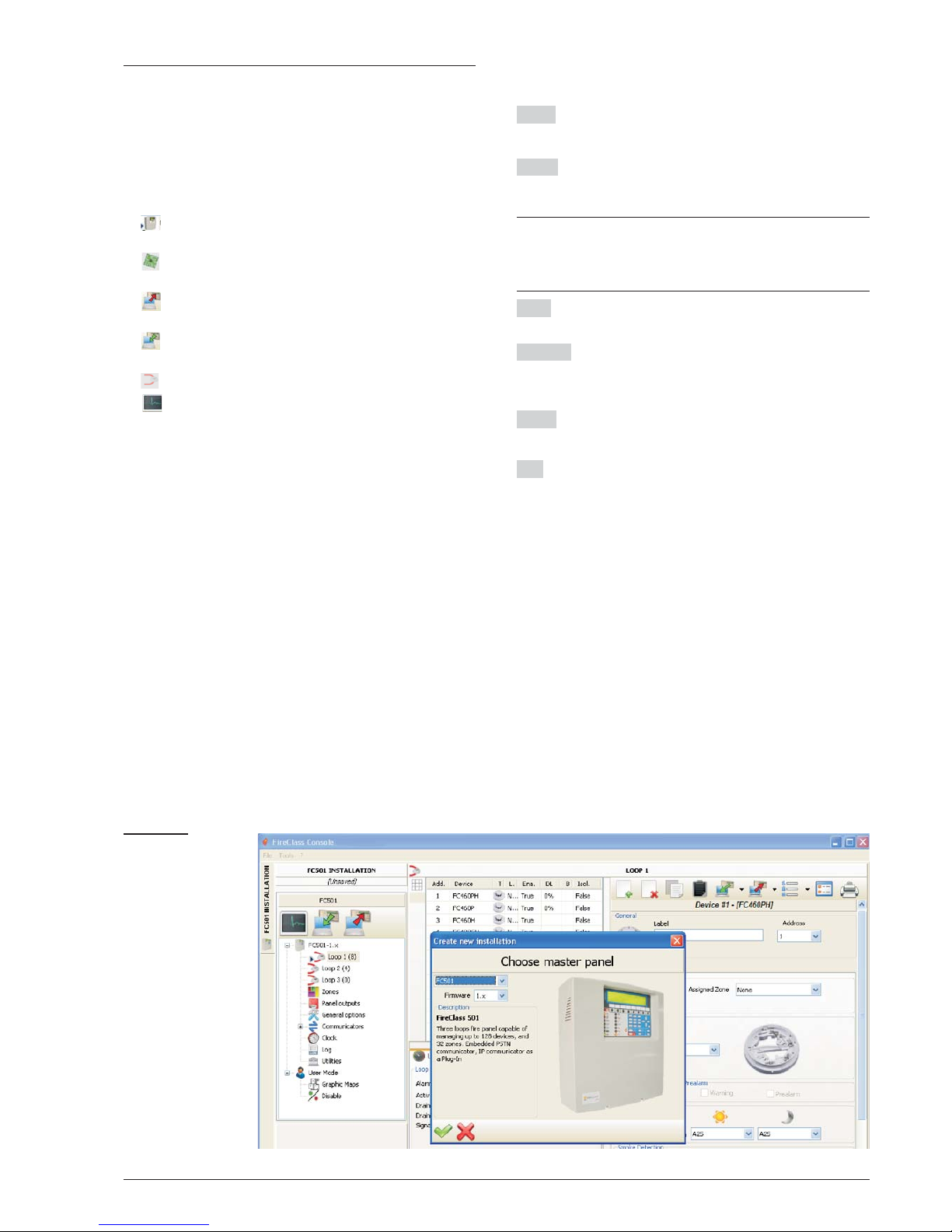
Main window
From the FireClass Console main screen, select "File"
and then "New", to display the window as shown in Fi
gure 16 where you can select the Firmware Release of
the Control Panel to program. Click on the green tick to
accept the selection. The following sections describe
the File, Tools, and Help menus.
n
Icons
Ø
Opens the window "Panel Details" (Figure 18 )
where you can check/insert various programming.
Ø
Check Panel details, enter the name and address
of the Control Panel/Customer.(Figure 18)
Ø
Download the programming (via serial link) to the
connected control panel.
Ø
Upload the programming of the connected Con
-
trol Panel.
Ø
Select the Loop for inserting devices.
Ø
Start operations in Real Time. This feature al
-
lows you to view the status of the FC501 control pa
-
nel in real time on a computer using the FC500IP
module connected to the network or using the serial
port.
n
File menu
The menu File: New, Open, Save, Save as, Close,
Exit will allow you to manage customer account data.
New creates a New installation and assigns the fac
-
tory default values to all programming parameters.
Open retrieves a previously saved customer installa
tion file. Locate the required installation file and double
click it to open it.
+
You can have more than one installation file open at
the same time. Pay attention to the tabs on the
left-hand side to ensure you are editing the correct
file.
Save If the installation data is modified, click on “Save” to
save the changes to the current installation.
Save as If you have created a new installation or want
to save an existing installation under a new name then
click on "Save as".
Close closes the current installation. You will be prom
pted to save any changes made.
Exit closes Fireclass Console. You will be prompted to
save any changes made to the current installation.
32 Addressable Fire Panel FC501
Figure 16 From
File menu and then
"New".
Page 33
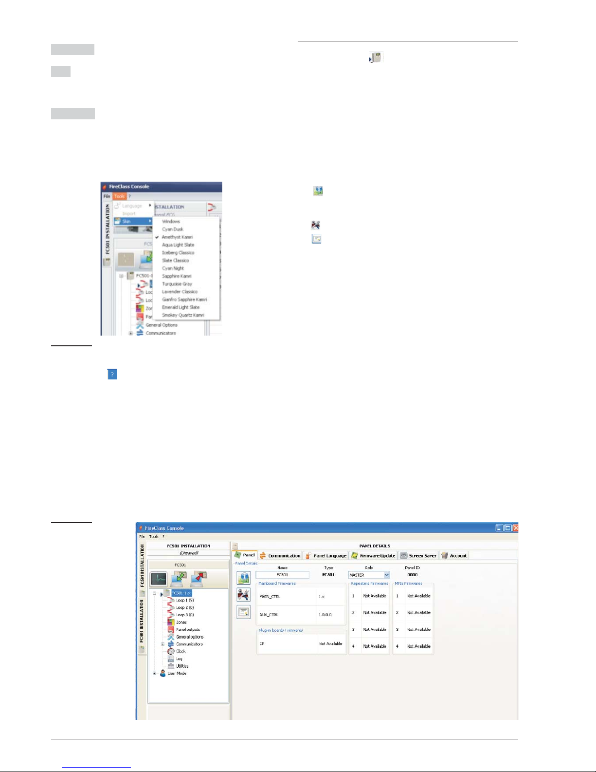
n
Tools menu
Language See paragraph "Select language" on page 32.
Skin To change the look of FireClass Console, click on
Tools and then "Skin" that allows to choose the available
looks from a list.
Advanced In this section you can set the Tooltip du
-
ratio. Load the driver to use the USB. It is also possi
ble to associate the files .FCI (files generated by the
programming/management of the fire system) with
FireClass console.
n Help Menu
Click on the Help option and a technical support file will
open. This application allows you to learn about and
use of FireClass Console.
Panel Details
Click on this icon and the following menu tabs will
be displayed (Figure 18):
- Panel
- Communication
- Panel Language
- Firmware Update
- Screen Saver
- Account.
n
Panel Details Menu
In this window, you can enter the name of the Panel/Cu
-
stomer.
Ø
Check the firmware version of MainBoard, Loop
controller, User Interface, Repeater and FC500FMI
module.
Ø
restores the Control Panel to the factory default.
Ø
opens the Installation Manual.
PC PROGRAMMING 33
Figure 17 To modify the window look (skins).
Figure 18 Control
Panel Details win
-
dow.
Page 34
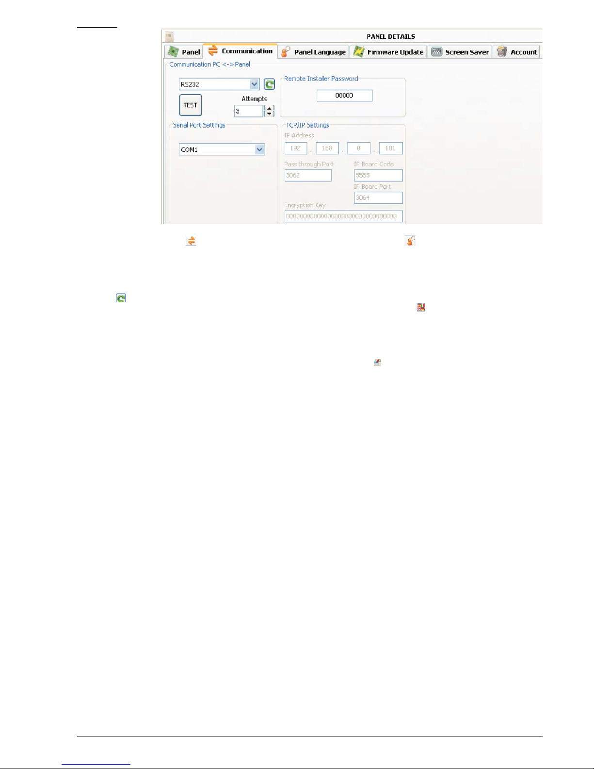
n
Communication Menu
In the Communication menu, you can choose the con
nection mode between the Panel and the PC: TCP/IP,
RS232 or USB.
Click on to update the type of connection. Click on
the TEST button to verify the functionality of the con
nection status. In the TCP/IP mode, it is necessary to
enter the FC500IP parameters and the Installer password already in the system.
The IP Module screen is used to program the parameters
corresponding to the IP Module as described below.
Ø IP address – Enter the IP address assigned to the IP
Module you wish to program or, if DHCP (dynamic IP
address) mode has been selected, contact the network
administrator to request details of the IP address assigned to the IP Module. Alternatively, follow the procedure outlined in the “View IP address” paragraph to
view the IP address on the control unit display.
Ø
Dynamic DNS Service – Control and monitor the pa
-
nel remotely using ethernet - a dynmaic DNS service.
Graphic maps can now be used without a static IP ad
-
dress assigned by an internet provider to the supervi
-
ser site. Add the necessary fields to the configuration
software in the FireClass Console. This allows the user
to connect to the control remotely using a fixed literal
domain name (for example, mysupervisedsi
-
te.dns.org). The user can avail of this site instead of a
numeric IP address.
The default setting is 192.168.0.101.
Ø
IP Module port – Enter the details of the port assi
-
gned to the IP Module you wish to program (contact
the network administrator).
The default setting is 3064.
Ø
IP Module code – Enter the access code assigned
to the IP Module you wish to program. The default
setting is 5555.
Encryption key – Enter the encryption key assigned to
the IP Module you wish to program. The default setting
is 32 zeros.
n
Language Menu
The Language menu allows you to change the system
language (User Interface or Repeater) to any of the lan
-
guages currently loaded using the following steps:
1. In the Loaded Language section, select Change
System Language .
2. Select the language and the device (User Interface
or Repeater).
3. Select to override the language in the Control
panel memory.
4. When the download of the new language is complete, the panel will start to use it and it will update
any peripherals, if necessary.
34 Addressable Fire Panel FC501
Figure 19 Com
-
munication window.
Page 35
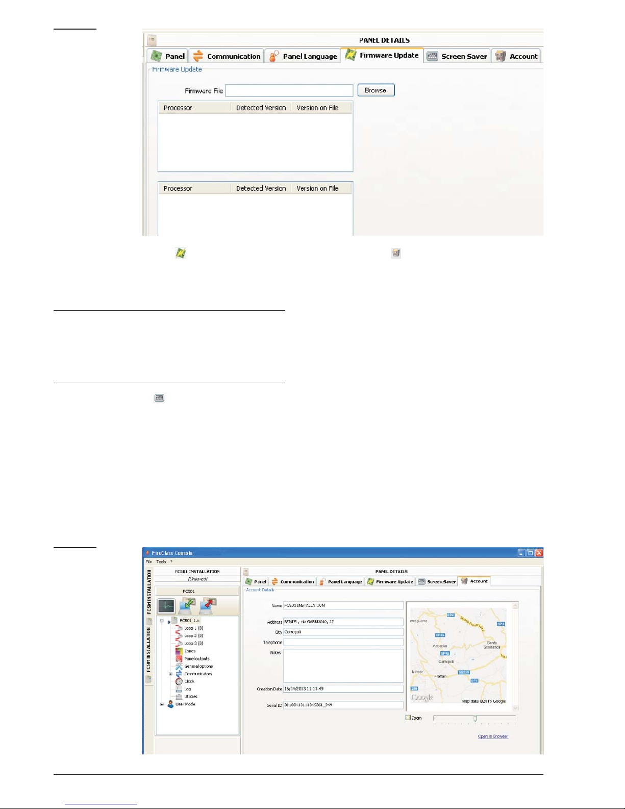
n
Firmware Update menu
Click on “Firmware Update” (see figure 20). From a so
-
urce file, a Firmware Update of all system interface in
cluding the Mainboard, User interface, Loop controller
and Repeater can be carried out.
+
If the FC500REP repeater has a Firmware V3 or
less, and the language is Italian while it is English
on the Panel, the installer will have to realign the
strings of languages after the firmware update,
using the language change process (see Pro-
gram 8 Key-System).
n ScreenSaver menu
In the ScreenSaver menu it is possible to insert 4 lines
of text (such as Installer address/telephone) which will
be loaded on the display of the User Interface when the
panel is in the stand-by status. The four rows can include: Steady, Scroll or Blink.
n
Account Menu
In the Account menu enter the account data, and for better
identification of the account, after entering the address (lo
cation) by clicking on the address field, the software will
attempt to find the address using Google Maps (if an acti
ve internet connection is present).
PC PROGRAMMING 35
Figure 20 Firmwa
-
re Update window.
Figure 21 Account
window.
Page 36
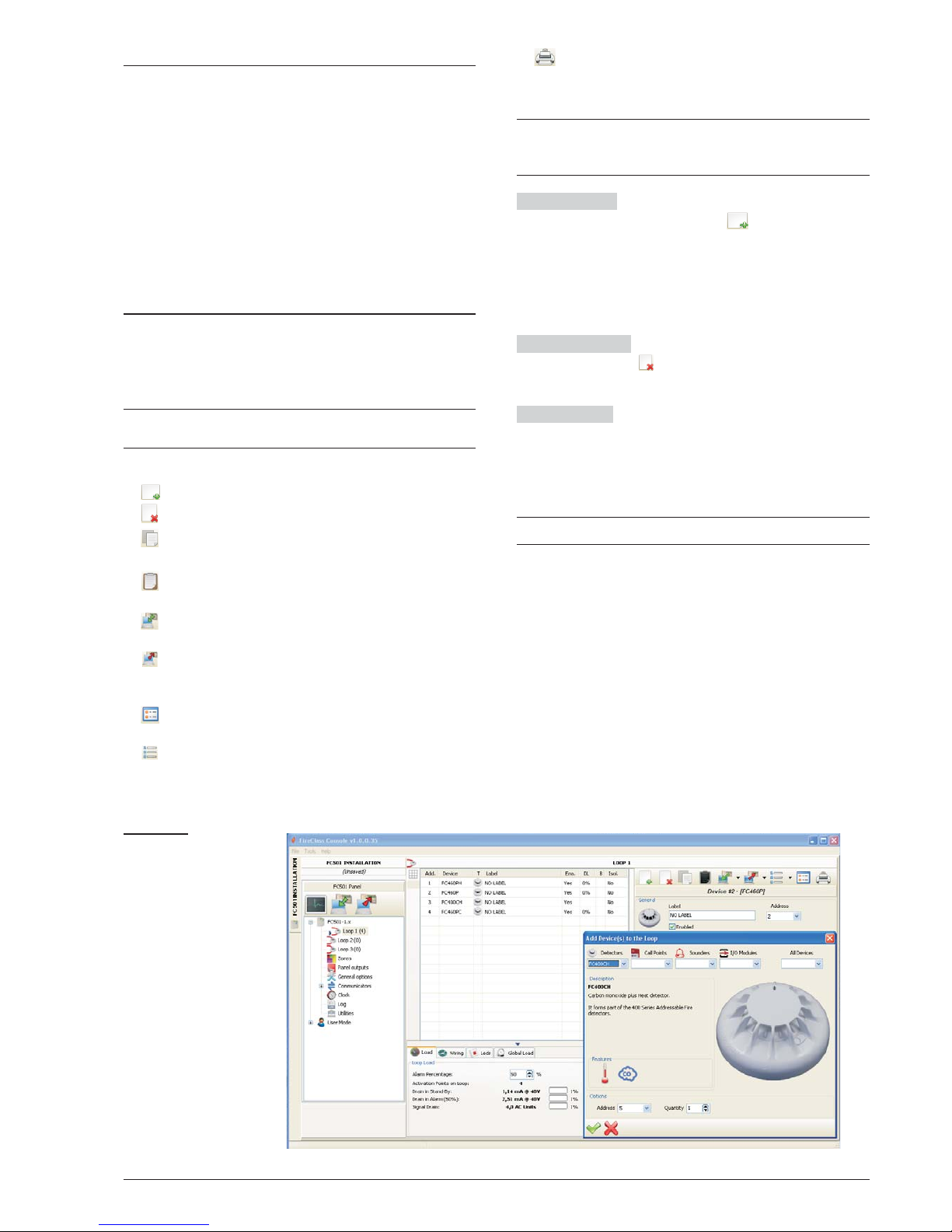
Programming Pages
The programming pages of the system are:
-Loop devices
-Zones
-Panel Outputs
-General Options
-Communicators
-Clock
-Log
-Utilities
-User mode
More details on these pages are provided in the follo
-
wing sections.
Loop Devices programming
In the window on the left, click on the panel name to ex
pand the tree view. Then click on the required loop (1,2
or 3). The devices programming window will be displa
yed (Figure 22).
+
On the right of Loop1 or Loop 2 or Loop3, the cur
-
rent number of devices is shown in brackets ().
n
Description of the icons in the tool bar.
Ø
Add Device: select new devices.
Ø
Remove device: remove the installed devices.
Ø Copy device on the clipboard: allows you to copy the
device data to the clipboard for use in another account.
Ø Paste clipboard content: allows you to add device
data previously copied to the clipboard.
Ø Read Loop: allows you to upload the current loop
data from the panel (via the serial data link).
Ø Send Element(s): allows you to download the
current loop data to the panel (via the serial data
link).
Ø
Device’s details: this open a new window to allow
you to see status of the device.
Ø
Selection: allows you to select all devices or invert
the current selection.
Ø
Print to file: the list of devices of the selected loop
can be printed to a .csv file . The .csv file can be edi
-
ted using Microsoft Excel.
+
If different devices have common programming pa
rameters, you can use the multiple selection of the
devices and assign the same parameters.
Select devices
Click on Panel 1, select Loop 1 or Loop
2 or Loop 3, click on “new device” . The window in Fi
-
gure 22 will display. Select the programming device,
check the address, (autoaddressing) and click on the tick
3 (Enable) to add the device to the loop. For others devi
-
ces, repeat the same procedure. The detector type is
shown by the icon in the Features field.
Remove devices Select the device in the list. Click on
“Remove device” . Click YES to remove or NO to
cancel (see Figure 22).
Loop Loading
The Loop Load section is located at the
bottom of the programmed devices list (Figure 23). In this
section the number of Activation points on the loop, the
Drain in stand-By, the Drain in Alarm and the Signal
Drain are displayed. The Alarm percentage can be ad
-
justed.
+
The remote LEDs may be entered in the calculation.
The percentage shown in the “Loop drain in alarm (50%)”
is the programmed value in “Battery calculation” an option
of Utilities page (see dedicated paragraph), for the battery calculation after the cable length is entered. It is possible to choose the type of cable if you have a database.
36 Addressable Fire Panel FC501
Figure 22 Devices
programming win
-
dow
Page 37
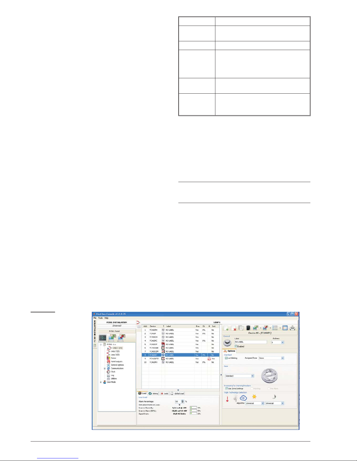
n
Loop wiring Calculation
The Loop Wiring is located beside the Loop Load tab.
This gives you the maximum permitted resistance of the
loop based on the cable length and the Alarm Percenta
ge. If cable data is available from the Utilities section
then suitable cable may also be shown.
n
Detectors parameters programming
Click on a device in the Device list. The relevant device
programming window will be shown on the right (every
device has the dedicated programming window).
For the detectors (see figure 22);
in the First section (GENERAL):
Ø
Enabled:atick[
3] indicates that the detector is enabled.
Ø
Label: this is for the editable device-label. The system
will use the label as the device identifier
.
Ø
Address: in this field you can modify the address of
the detector.
OPTIONS section:
LED Blinking: a tick [
3] indicates that the LED detec
tor will flash.
Ø
Assigned Zones: each fire detector, Input module
and Manual call Point can be associated with 1 of the
available software zones (32 for FC501 control pa
-
nel). If a device goes into ALARM status, the zones it
is assigned will also go into ALARM status.
Base: In this section it is possible to select the base for
the detector by clicking on the available bases. When
the sounder base type has been selected, a new programming tab Base is made available which opens the
sounder base programming page. On this page the trigger zones, the trigger points and the trigger event conditions can be selected and the following parameters can
be configured:
Parameter Result
Enabled
When selected, the base is enabled.
Otherwise the base is disabled
Label 20 characters base label
Silenceable
Sounds until SLIENCE/RESOUND
SOUNDERS button is selected. Oth
erwise sounds until RESET button is
selected
Set As SC1
When selected, the base will behave
as the Sounder Circuit 1 SC1
Monostable
When selected, the base sounds until
the MONSTABLE OUTPUTS TIME
elapses
Ø
Remote LED In this section it is possible to activate
the programmable Remote LED of the detectors.
The detectors have an output used to drive the remo
te LED. This output is only activated for detector
alarm to which it belong. Now, it will be possible to
program it to activate for other events, exactly as it
happens for the other panel outputs, as well as for
the detector alarm which it belongs.
+
This option (Remote LED) will be possible to program
also on control panel User interface, in the program
-
ming page of the detectors.
PROCESSING for WARNING/Delay to Alarm section:
this determines the actions the control panel will perform when the device threshold is exceeded.
Ø Use zone settings: the detector uses the parameters
of the assigned zone; if this option is disabled, the Warning and/or Delay to Alarm time can be manually selected.
Ø
Delay to Alarm: the control panel will activate the
ALARM delay
.
Ø
Warning: the control panel will activate a WARNING
signal.
Depending on the type of detector: Smoke, Heat, Smoke
and Heat, Heat and Carbon Monoxide (CO), Smoke Heat
PC PROGRAMMING 37
Figure 23 Detec
-
tors parameters pro
-
gramming Window
Page 38

and Carbon Monoxide (Co), will have three sections:
OPERATING MODE HEAT DETECTOR SECTION:
Day mode- Night mode for Temperature detec
-
tor (see table 8), choose the Class of the selected de
tector.
OPERATING MODE SMOKE DETECTOR SECTION:
Day mode- Night mode for Smoke and Heat
detectors:
Ø Drift Compensation: Drift compensation effects op-
tical smoke sensors only. It will supply a precise
analysis about dust accumulation, and therefore, the
alarm threshold will be modified accordingly (false
alarms).
Ø Default: for smoke detectors only and for Smoke and
Heat detectors only;
Ø Enhanced: for Smoke and Heat detectors only;
Ø
Sensitivity: Sensitivity can be set: Low, Medium
and High.
OPERATING MODE CARBON MONOXIDE SECTION:
Day mode- Night mode for Co and Heat detec
-
tors:
Ø
Default
Ø
Enhanced
Ø
Disabled
Ø
Sensitivity, this can be set to: Low, Normal or High.
For the FC460PC detector (Smoke, Heat and Co) can
be set to: HIGH IMMUNITY or UNIVERSAL, in the
TRIPLE TECHNOLOGY DETECTION.
+
Click on to open or close the relative section of
parameters programming
+
If a detector linked to an Output or Input-Output Mo
-
dule, is disabled (remove a tick [3]in the proper sec
tion), a window will show to ask confirmation. Click on
Detail to see further data.
+
For the sirens of the FC410LPA/S series and the
base FC430LPA/S, in the “Sounder Options” sec
tion you can set the tone, volume and frequency of
flash of the beacon.
+
For the sirens of the FC410LPSY/AV series you
must also choose the Subtype.
n
Input module parameters programming
Click on an entered Input Module, the relevant pro
gramming window will be shown as per the following
description.
First section: as per the Detectors section;
Assigned zone: as per the Detectors section;
Second section: select the operating mode style: B, C.
There are 2 operating mode style: B, C;
Ø B style: two wire connection mode: the short-circuit
condition as an Alarm condition.
Ø C style: two wire connection mode: the short-circuit
condition as a Fault condition.
+
As different styles are selected, the electrical operating diagram changes
PROCESSING for WARNING/ Delay to Alarm sec
tion: see the same section in the Detectors parame
ters programming.
+
For every digital input of loop devices, the Restora
-
ble warning parameter (when Warning option is se
-
lected for the input) can be programmed. This can
also apply to the Multiple Input-Output modules but
not for the detectors. When this option is program
-
med for a certain input, the control panel will enter
the Warning status when the appropriate conditions
are detected by the input, and will exit this status
when the loop device goes back to standby status.
+
When the loop device is activated and the War
-
ning event is generated, the LED of the device will
be switched ON. When the event is restored, the
LED will be switched OFF.
For the FC410DDM module only, it is possible to set
the thresholds of gas detection by selecting Conventio
nal (for conventional detectors), Gas Source or Gas
Sink (for signalling detectors). In addition:
Ø
LED blinking: click on to enable/disable signaling
LED module.
38 Addressable Fire Panel FC501
Detector
Class
Typical application
Temperature °C
Max. Application
Temperature °C
Min.Static
Response
Temperature °C
Max.Static
Response
Temperature °C
A1 25 50 54 65
A2 25 50 54 70
B 40656985
C 558084100
D 709599115
E 85 110 114 130
F 100 125 129 145
G 115 140 144 160
Table 8 Detector classification Temperature - Detectors will conform to one or more of the following classes: A1, A2, B,
C, D, E, F or G . Manufacturers may optionally give additional information concerning the type of response exhibited by the
detector, by adding the suffix S or R to the above classes. Detectors, with a suffix S to their class, do not respond below the
minimum static response temperature, even at high rates of rise of air temperature. Detectors, with a suffix R to their class,
incorporate a rate of rise characteristic, which meets the response time requirements for high rates of rise of air temperatu
-
re even when the air temperature starts substantially below the typical application temperature (EN54-5:2000).
Page 39

Ø
External Power: click on to enable/disable an exter
-
nal 24Vdc PSU.
For the MIM module, you can enable Fast mode in
Style B or Style C/NO connection. When Fast Mode is
enabled, the activiation of the module will be detected
by the control panel within 2 seconds.
+
A short circuit fault will be detected quickly while its
restoration will be slow as with the other faults.
Default: disabled.
n
Output module parameters programming
Click on an entered Output Module, the relevant pro
gramming window will be shown as per the following
description.
FIRST section: as per the Detectors section.
SECOND section: Trigger zones; each Output module
can be triggered by up to 4 of the 32 available software
zones for FC501 panel. An Output module will be acti
vated when any of the selected zones are triggered, re
ach the status condition configured in the Fourth
section (Zone row).
Base: in this section, the base for the Output module
can be selected; click-on available bases (for
FC430SAM and FC430SAB only). Once the "sounder"
base is selected, a new programming tab labelled
"base" allowing access to the sounder base program
ming page, where the trigger zones, the trigger points,
the trigger condidtions can be selected and the following parameters can be configured:
Parameter Result
Enabled
When selected, the base is enabled. Otherwise the base is disabled
Label 20 characters base label
Silenceable
Sounds until "SILENCE/RESOUND
SOUNDERS" button is pressed
when selected. Otherwise sounds
until "RESET" button is pressed.
Set As SC1
When selected, the base behaves
as the Sounder Circuit 1 SC1
Monostable
When selected, the base sounds
until the monstable outputs time
elapses
Beacon: Activate the blinking or glowing (ON).
THIRD section: Trigger points. each output module can be
assigned to 3 Activation points : in this case the Output Mo
dule is activated when at least one of the Input points to
which it belongs is in a alarm status, indicate:
Ø
the loop which the device is connected to;
Ø
the device address.
FOURTH section: Options, these options will allow you
to select the conditions that will activate the output module:
Ø
Zone warning, Zone fault, Zone Delay to Alarm, Zone
Alarm, Zone Double Knock, Zone Test;
Ø
Point warning, Point fault, Point Delay to Alarm, Point
Alarm;
Ø
Panel warning, Panel fault, Panel delay to alarm, Pa
-
nel alarm,
Ø
Network fault.
It is also possible to program the Output Module as: Si
-
lenceable, Set as SC1, ACTIVE ON DISABLEMENT,
MONOSTABLE, TIMED WARNING (see Outputs pro
-
gramming).
Ø
Linked Delay: see the same option in the paragraph
“Panel Output Programming”.
For the following types of devices:
FC410LPAV (all versions)
FC430LPASB
FC430SAB (with FC430SB),
In addition to those certified to EN54-23:
FC410LPS-R/W
FC410LPBS
FC430LPBSB,
It is possible to separate the programming of the Soun
der and Beacon, in two different programming tabs. The
two tabs, for Sounder and Beacon, have the same pro
gramming options, except for "Set As SC1", which will
be present only for the Sounder output.
+
It is not possible to separately enable/disable the
two output channels.
+
The separate programming of the Sounder and Be
-
acon of the devices (named previously), it will be
possible also by Control Panel User Interface in the
Devices programming pages.
Pulse On: If the Pulse On option is disabled, the sounder sounds steady. If not, the sounder sounds a pulse (2
seconds on, 2 seconds off) as indicated by the following
options. In all cases, the tone of the sounder is based on
the selection in the Options page.
+
The sounder sounds continuously for the Fault,
Double Knock and Test events
+
Disable As General Options to make the Pulse
On options of the selected sounder different to the
settings in the General option > General Outputs
Settings page
Detector Alarm: If enabled, the sounder will pulse
when the programmed Alarm event is triggered by a
detector. Default: disabled.
+
The sounder will sound continuously when the pro
-
grammed Alarm event is triggered by a call point or
by the EVAC button, independently by the Detec
-
tor Alarm option set.
Delay to Alarm: If enabled, the sounder will pulse when
the programmed Delay to Alarm event occurs. Default:
disabled.
Warning: If enabled, the sounder will pulse when the
programmed Warning event occurs.
Default: enabled.
PC PROGRAMMING 39
Page 40

Sounder Options: In the programming page of the
loop sounders there are 3 controls to set the Tone, Vo
-
lume, and the Beacon frequency for Alarm, Delay to
Alarm and Warning event types so that each type of
event causes a different sound or LED blinking. If diffe
rent types of trigger events are active at the same time
for a sounder, this sounds with the highest priority tone.
+
Disable As General Options to make the Soun
-
der options of the selected sounder different to
the settings in the General option > General Out
-
puts Settings page
Default Volumes: maximum for Alarm and Delay to
Alarm, minimum for Warning.
Default Beacon Frequencies:0.5Hz.
n
Multiple Input-Output Module - Parameters
Programming (FC410MIO/FC410QIO)
Click on an entered Multiple Input/Output Module
FC410MIO (3 Inputs and 4 Outputs Module) or
FC410QIO (4 Inputs and 4 Outputs Module), see the
customized Manuals, the relevant programming win
dow will be shown.
The options descriptions are as per the Input and Out
put Modules paragraphs. In the field “Label” a
description of Input/Output Module will be inserted.
For Trigger Points see same section on "Output module
parameters programming".
OPTIONS section:
Ø Oppo interface: ActUnit/KeySafe, allows you to
manage the procedure for the automatic opening of
the doors of the factory / Office / Shop, Warehouse,
in case of fire. This avoids the breakage of these
structures. The outputs of this module can control
these actions.
Ø
LED blinking: click on to enable/disable signaling LE.
The FC410TSM Door Control Module (one Input/one
output) designed to close a fire door in case of alarm or
fault. The FC410TSM monitors:
- the external Power supply;
- Loop voltage Test, if the relevant option are enabled.
+
In an eventual connection on the right side (2 wires
connection), the module enables the yellow (isola
-
tor) LED blinking (Not correct installation)
n
Manual Call Point parameters programming
Click on a Manual Call Point (FC420CP, FC421CP) the
relevant programming will be shown as per the following
description. GENERAL section: as for the detectors;
OPTIONS section:
Ø
assigned zones: each Manual Call Point can be as
sociated with 1 of the available software zones (32
for FC501).
Ø
Led blinking: if this option is enabled, the Manual
Call Point LED will blink every Loop scanning.
40 Addressable Fire Panel FC501
Page 41
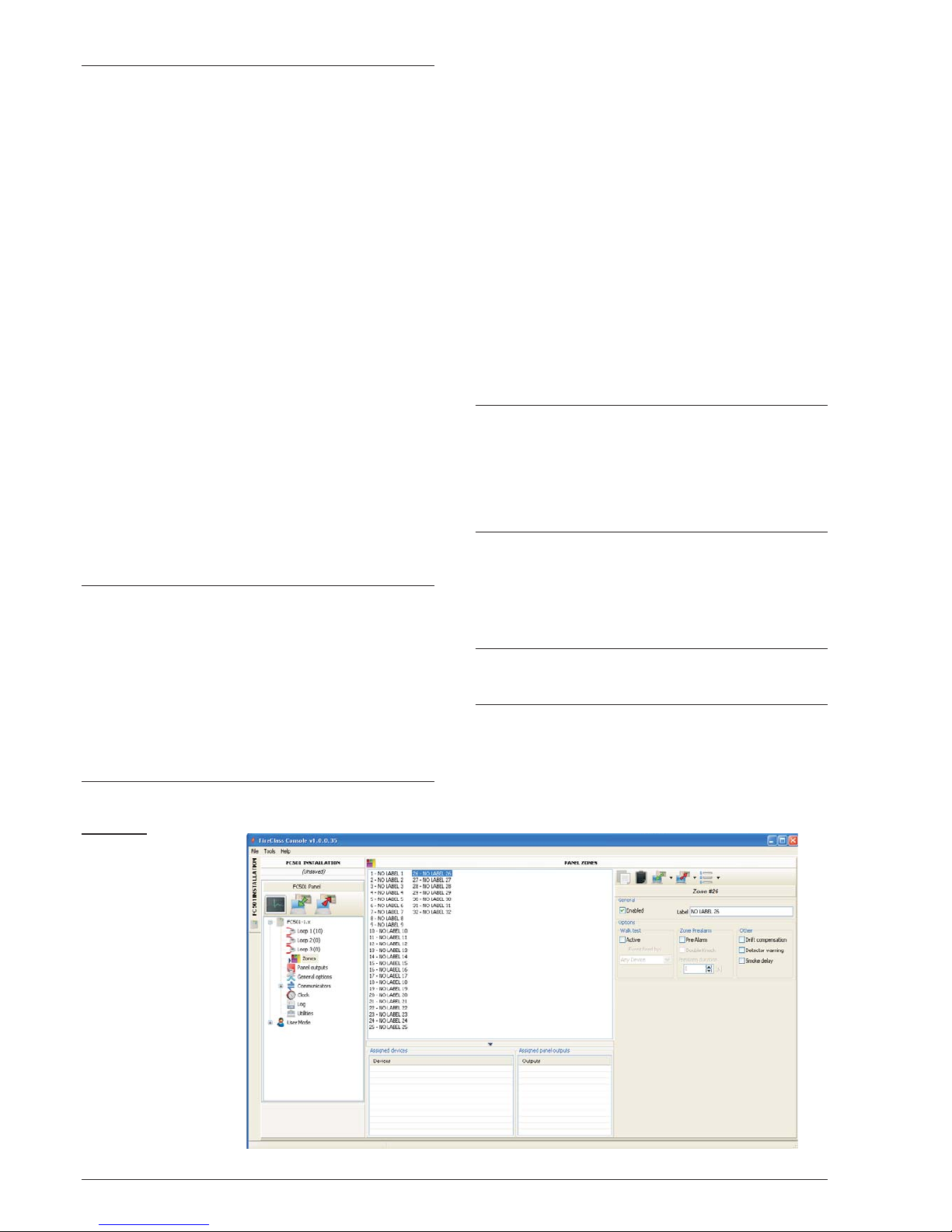
Zones programming
The Zones option from the panel tree menu will allow
you to access the software-zone parameters (see Figu
re 24 ). The software zones parameters will be applied
automatically to all the devices associated with the
zone concerned.
GENERAL section (FIRST section)
Ø
Enabled:atick[
3] indicates that the zone is enabled.
Ø
Label: this is for the editable device-label (up to 20
characters). The system will use the label as the
zone identifier.
OPTIONS section: a number of parameters can be
programmed in this section.
Walk test:
Ø
Active: if enabled, the zones in alarm status will acti
vate the programmed Outputs with Walk test event,
while the control panel will not generate an alarm.
Select if the event is fired by:
- Any device means Modules + CP + Detectors
- CallPoints means CPs only
- Detectors means Modules + Detectors (No CPs)
Delay to Alarm:
Ø
Delay to Alarm: if this option is enabled, the control
panel will activate the ALARM delay.
Ø
Double Knock: if this option is enabled and the zone
is in the Delay to Alarm status, when any other devi
ces (other address) associated to this zone are activated, the zone will immediately generate an Alarm
status.
+
If the "Use zone settings" option is not checked for a
device, it means that you can individually decide, for
that device, if it has to process Warning and/or Delay
to Alarm. Once you have decided that the device processes delay to alarm, its activation will cause the delay to alarm of the panel (with panel delay to alarm
time) and, because it belongs to a zone, that zone will
go into the delay to alarm status. If another point be
-
longing to the zone goes into Delay to Alarm, the Do
uble Knock option becomes active if enabled in Zone
programming page.
Ø
Delay to Alarm Duration: an input device program
med with Delay to Alarm time will generate ALARM
status when the delay to alarm time elapses. (see
parameters programming detector).
Select the Delay to Alarm time.
The delay to alarm time can be set from 0 seconds to
300 seconds in 1-second steps. Other:
Ø
Drift Compensation: see the same option in “Para
meters detectors Programming”.
Ø
Detector Warning: if this option is enabled, the con
trol panel will activate a WARNING signal.
N.B. To activate the Warning option for a Module,
tick the corresponding box on the Module program
ming screen.
Ø
Smoke delay: for each zone, you can program the dela
yed activation of the smoke detectors. The SMOKE
DELAY (60 seconds/30 minutes) parameter, when set,
applies to all smoke detectors assigned to the selected
zone the alarm verification algorithm as described in the
EN54-2.
+
Under the list of Zones (Zone Programming page,
see figure 24 ) two windows are displayed which de
-
vices and what outputs are enabled on it. If you click
the right mouse button on a Device in the list, a new
menu will be displayed. Selecting Device Details will
open a new window, where it is possible to see what
points and what output is assigned to the device.
COMMUNICATORS section:
PSTN: each zone can be associated with one or more
voice messages linked to an Alarm, Delay to Alarm,
Start-up, Breakdown or Walk Test event. These may be
sent to a maximum of 32 telephone numbers.
IP: see PSTN above.
+
The Communicators section will be activated after
that the PSTN and/or IP communicator are enabled (double clicks) in the General Options page.
PC PROGRAMMING 41
Figure 24 Zones
Programming win
-
dow.
Page 42
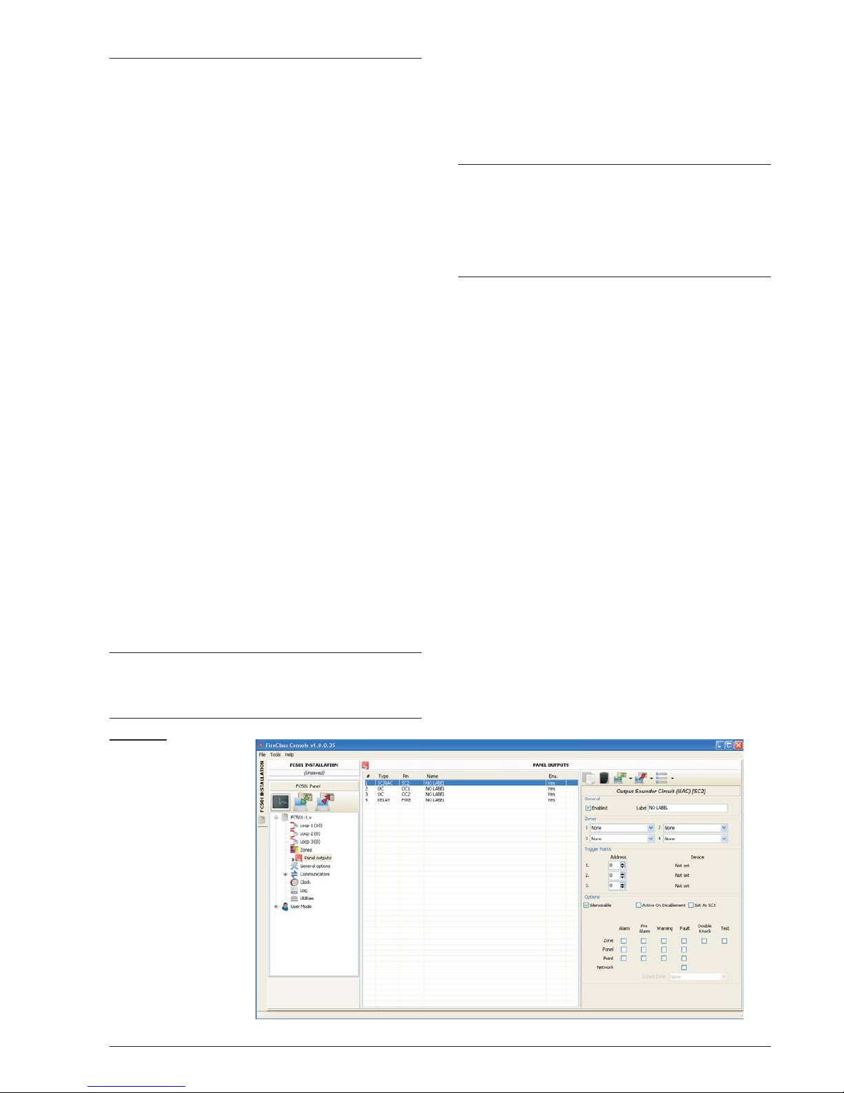
Outputs Programming
The Panel Outputs option will allow you to access the
outputs parameters. The relevant programming will be
shown as per the following description (see Figure 25).
n
SC1, SC2 Outputs
Supervised/Silenceable/Bypassable (Disabled) Alarm
Outputs.
Output ACTIVE: positive pull-up to 27.6 V on the [+] ter
minal; negative pull-down to0Vonthe[–]terminal.
Click on an Output, the relevant programming window
will be shown:
In the GENERAL section:
Ø
Enabled: a tick [
3] indicates that the Output is ena
-
bled.
Ø
Label: this is for the editable Output-label. The
system will use the label as the Output identifier.
In the ZONES section, each Output can be triggered
by up to 4 of the available software zones (32 for
FC501 fire panel).
In the TRIGGER POINTS section, each Output can be
triggered by 3 Input Points. For each Point it is neces
sary to indicate the address.
In the OPTIONS Section you can select the conditions
that will activate the outputs. For example: if the
“Zone warning” option is enabled, the control panel
will activate the output when one of its associated points
goes into Warning status.
Ø Warning Zone, Fault Zone, Delay to Alarm Zone,
Alarm Zone, Double knock (see Zones programming), Walk Test Zone;
Ø Point Warning, Point Fault, Point Delay to Alarm, Po-
int Alarm,
Ø Panel Warning, Panel Fault, Panel Delay to Alarm,
Panel Alarm, Network (RS485) fault
Ø Set as SC1
If this option is enabled, the output behaves as the Sounder
Circuit 1 (SC1).
+
When Set as SC1 has been enabled, the
SOUNDERS FAULT/DIS LED blinks if any output
"set as SC1" fails. It remains Glowing if any output
"set as SC1" is disabled.
Ø
Silenceable The output, if activated, can be Silen
ceable by checking this option. In the case of output
silenceable, once silenced, it will be automatically re
activated in the case of a new fire event.
Ø
Active on Disablement Click on this option to acti
vate the programmable SC outputs when any part of
the system is disabled.
+
This feature will be available for all programmable
control panel outputs and for loop modules which
provide dry contacts. This is the list of the devices
affected by the modification: programmable control
panel outputs: OC1, OC2 and FIRE.
Loop modules: FC410RIM, FC410SIO, FC410MIO,
FC410QMO, FC410QRM, FC410QIO
Ø
MONOSTABLE: Allows the relevant output to auto
matically deactivate when the "MONOST.OUTPUT
TIME" elapses.
Ø
As General Options: override the Pulse On local
selection forcing the selection of the Pulse On in
General Options settings.
Ø
Timed Warning: becomes available if a warning
trigger event is selected for the output. If enabled, the
sounder will activate when the programmed warning
trigger events happen, for the time specified by the
Timed Warning duration option, the sounder will
activate. Default: disabled.
Ø Linked Delay: one of the 5 available timers (set
using the General Options page on Delays Thre-
sholds) can be associated with an output activated by
a zone, point or control panel alarm. The output will be
activated by the programmed event, after the delay indicated by the Timer.
n OC1, OC2 Outputs
These are programmed, NON-SUPERVISED, non-silenceable, bypassable (Disabled) outputs.
These are normally-open terminals (open-collector)
which close to ground when the corresponding zones go
into alarm status. These terminals will remain closed to
ground even after the generating event has ended.
42 Addressable Fire Panel FC501
Figure 25 Outputs
programming win
-
dow.
Page 43
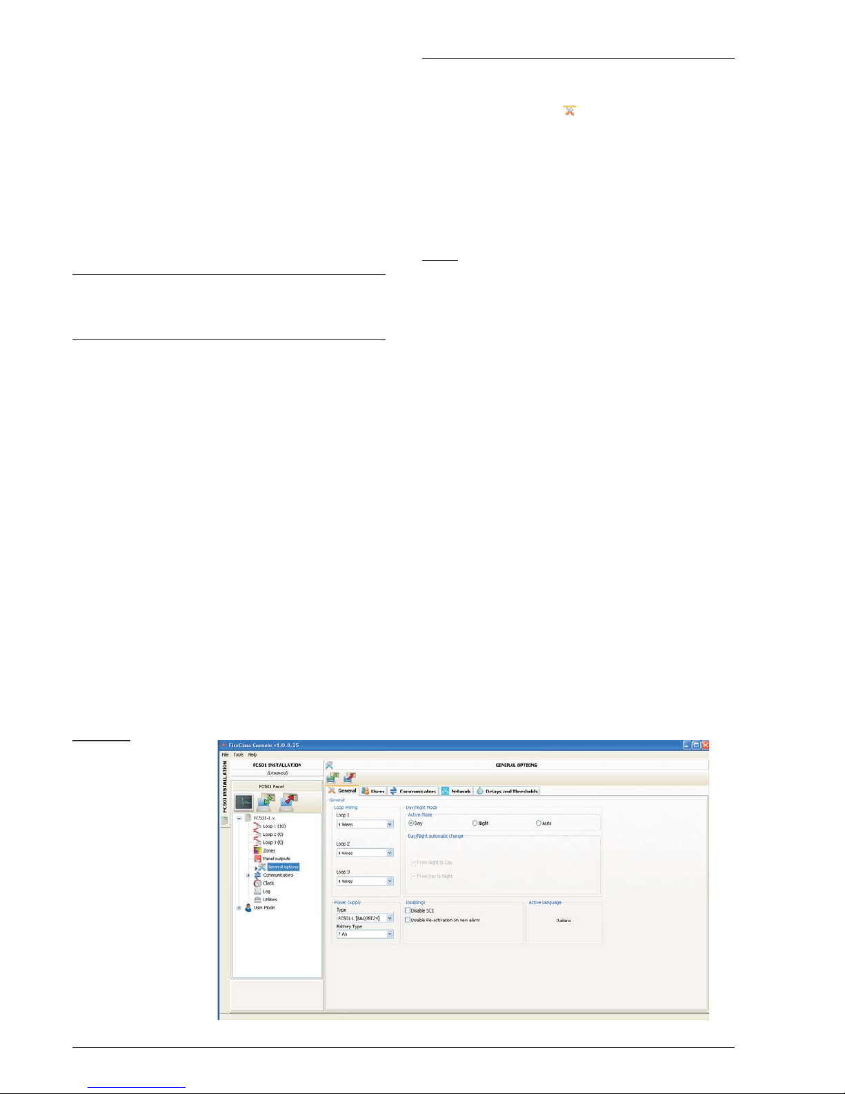
See the descriptions of the common parameters as per
SC1, SC2 Outputs.
Ø
Backup PSTN line For the output OC1 ONLY, use to
drive an external relay to switch on the secondary te
-
lephone line, if any, in the case of a failure with the pri
-
mary telephone line.
The Options section contains parameters for setting
the conditions to activate the outputs (see same section
in the SC Outputs paragraph).
n
Relay Outputs
Ø
Relay FIRE Non-supervised Fire output. Dry contact
relay for non-supervised devices.
Ø
Relay FAULT Non-supervised Fault output. Dry
contact relay for non-supervised devices.
+
EN54-2 certification applies ONLY when FAULT
output is not J (EN 54-1) type, therefore this output
MUST NOT BE UTILIZED to manage Fault tran
-
smission devices.
The Options section contains parameters for setting
the conditions to activate these outputs (see same sec
-
tion in the SC Outputs paragraph).
General Options programming
The Panel parameters can be programmed through the
General Options page (see Figure 26).
In the General section :
Ø
Loop Wiring: select a 2 wire connection or a 4 wire
connection for the Panel Loop configuration.
When the "2 wires" option is selected, it is possible to
connect devices on both left and right sides of the loops
(two spurs). This provides the capability to connect up
to 6 spurs to the panel, mimicking a 6 zone conventional
panel.
Notes
1. In the description of events, the devices are indi
cated as belonging to a loop. In the case of open
loops, it is not possible to distinguish between the
left and right side. The loop concept, however, will
not be meaningful by definition, and localization will
be performed via zones, as for conventional pan
els.
2. If devices are addressed by the Service Tool, there
are two options to set them in 6 zones which corre
spond to the 6 spurs:
a) Connect addresses from 1 to 16 to the left side of
loop1, from 17-32 to the right side of the loop and so
on. Perform the enroll procedure and choose the
"By address" option for zone assignment (devices
on the left side of loop 1 will be assigned to zone 1,
those on the right side of loop 1 to zone 2 and so on.
b) Assign the correct zone to each device via the
PC Console or the control panel LCD.
3. If the devices are not addressed, the mapping procedure will be performed to locate each device and
assign the proper zone to it.
PC PROGRAMMING 43
Figure 26 General
Options window
Page 44

Ø
Day/night Mode: select the operation mode: Day
Mode , or Night Mode : or select Automatic
to set the time (hour and minutes) of transition from
one mode to another.
Ø
Disable screen saver: allows the user to enable or
disable the screen saver on the main page of the
control panel LCD. The user can program the screen
saver from the control panel User Interface or the Fi
reClass Console. If the screen saver is enabled, it is
displayed on the LCD. If it is disabled, it does not ap
pear. This feature is not available for repeaters.
Ø
Power Supply: select the Power Supply of the
system: BAW50T24 or BAW75T24.
Ø
Disabling: Disable SC1.
- Allows disabling of the SC1 output (enabled by de
fault). This Output is programmable. It is activated every
time the control panel goes into ALARM status.
Ø
Re-activation of new alarm. The following options
can be selected:
- "No Reactivation" where outputs are not reactiva
ted once silenced.
- "Alarm on other zone" where the outputs will be re
activated when a new zone goes into Alarm.
In the USERS section , it is possible to change the
installer code and user code. Each code must be 5 di
-
gits and can include digits 0-9.
Ø
The Installer code allows you to manage the 3 ac
cess Levels of control panel: L1(View), L2 (User),
L3 (Installer).
The default installer code is 00000:
one click only - the password is present.
a second click - the installer password is enabled.
Ø The User code allows you to manage 2 access Le-
vels of control panel: L1(View) and L2 (User).
The default User code is 11111:
one click only - the password is present.
a second click - the user password is enabled.
Ø
Lock Installers Password: if you select this option,
it is not possible to perform the procedure to change
the password Installer from the panel User Interface:
Program Menu, 0=L3 PWD Key.
In the COMMUNICATORS section it is possible to
enable the PSTN functionality and the FC500IP module.
In the PSTN section:
Ø
one click only - the PSTN is present, but not enabled.
Ø
a double click - the PSTN is enabled.
When PSTN is enabled you can also select whether to
enable both events, alarm and fault or one of two.
IP section:
Ø
one click only - the FC500IP is present, but not
enabled.
Ø
a double click - the FC500IP is enabled.
When IP is enabled you can also select whether to ena
-
ble both events, alarm and fault or one of two.
In the NETWORK section: a tick [
3] performs the
following actions:
Ø
Enable Network.
Ø
Allow buzzer silence which silences a device that
is activated in every part of the network.
Ø
Enable Repeaters and FC500 MFI modules in the
Network Repeaters section and Network MFI section.
- One click only the Repeater and FC500MFI are
present, but not enabled.
- A double click the Repeater and FC500MFI are
enabled.
For the FC500MFI module, see the Programming
from the panel section.
+
The Repeater address can be inserted from the pa
-
nel (see Programming from the panel section).
DELAYS and THRESHOLDS section In this sec
-
tion, it is possible to program:
Ø
The ALARM DELAYS: you can select 5 timers.
When selecting the output in the Panel Outputs
page, the timer will be set in the Linked Delay option.
Ø
The PANEL DELAYS
Ø
Investigation Time: a Delay will be added automati
cally to the Delay to Alarm remaining delay, when the
Investigate Key will be pressed.
+
The sum of Investigation Time and Delay to
Alarm Time must not exceded 10 minutes
Fault delay: this field controls how long it takes for the
panel to signal a Mains failure.
The Amber signalling LED (Power Supply Fault) will be
ON and the relevant event will be shown on the display.
Delay to alarm duration: an input device programmed
with Delay to alarm time will generate ALARM status
when the delay to alarm time elapses.
Delay to Alarm status is signalled by:
Ø an audible signal emitted by the control panel.
Ø blinking on the DELAY TO ALARM LED (this LED is
on the Repeater FC500REP only).
Ø the message on the display.
Ø activation of outputs with programmed delay to
alarms.
Silence duration: when the control panel is in Night
Mode, the Silence delay is the maximum silence time of
the Outputs. To disable the Silence duration time, tick
the checkbox "Disabled" located to the right of the time
value entry.
Reset: program the Reset time ( min time: 2 seconds;
max time: 15 seconds.).
Monostable outputs time: When the “monostable” op
-
tion is set for the outputs, the monostable outputs
time defines, for the entire system, the period of time for
which the outputs remain active once triggered. Values
range from 1 minute to 30 minutes (The default value is
3 minutes)
Warning Sound Duration:This is the numeric value
defining the time of activation of outputs which have the
"Timed Warning" option set.
The value is valid for the entire system (every new trig
-
ger event of the programmed outputs will restart it).
Range:from 3 to 60 seconds.
Default value: 5 seconds.
Resolution: 1 second
The THRESHOLDS section is reserved for the DDM
Gas Detector;
Ø
SET: allows you to choose between 4 levels of threshold.
44 Addressable Fire Panel FC501
Page 45

General Output Settings
In this section, the behaviour of the Sounder Circuit 2
(SC2) and loop sounders can be configured at a system
level.
These configurations will be applied to the SC2 loop so
unders when As General Options is enabled.
Pulse On: If the Pulse On option are disabled, the soun
der sounds steady. If not, the sounder pulses (2 seconds
on, 2 seconds off) as indicated by the following options.
In all cases, the tone of the sounder is based on the se
lection in the Panel Settings for Simphony Sounders
and Panel Settings for AV Base Sounders sections.
+
The sounder always sounds continuously for the
Fault, Double Knock and Test events.
Detector Alarm: If enabled, the sounder will pulse
when the programmed Alarm event is triggered by a de
tector. Default: disabled
+
The sounder will sound continuously when the pro
-
grammed Alarm event is triggered by a call point or
by the EVAC button, independent of the Detector
Alarm option set.
Delay to Alarm: If enabled, the sounder will pulse when
the programmed Delay to Alarm event occurs.
Default: disabled.
Warning: If enabled, the sounder will pulse when the
programmed Warning event occurs.
Default: enabled.
n Panel Setting for Simphony Sounders and Panel
setting for AV Base Sounder
For each of the trigger events, Alarm, Delay to Alarm
and Warning, it will be possibe to select: the sounder
Tone, the sounder Volume, the Beacon flash rate.De
fault Tones: 7Hz Fast Sweep (Dutch Slow Whoop when
the Dutch language is selected) for Alarm and Delay to
Alarm, 2 Tone for Warning. Default Volumes: maximum
for Alarm and Delay to Alarm, minimum for Warning.De
fault Beacon Frequencies: 0.5Hz
Communicators Programming
The Communicators page is for programming the para
meters of the PSTN interface, of the FC500IP module
and of Panel events, as described below.
PSTN interface The PSTN interface section is activa
ted, after the PSTN Telecom interface has been ena
bled on the General Options page (Figure 26).
In the OPTIONS section:
Ø
Call attempts – Set the maximum number of at
-
tempts that the PSTN interface makes for each Te
-
lephone Number: set from 1 to 9, the default setting
is 3 attempts.
Ø
Iterations – Set the number of times the PSTN inter
-
face repeats the Voice Message: set from 1 to 9, the
default setting is 3;
Ø
Tone Check – If enabled , the PSTN interface con
-
trols whether it can obtain a Dialling Tone and if it can
obtain it move to the next step. If not, it will consider the
phone call failed and the hang up and try again.
Ø
Call All Telemonitoring – If the Call all Telemonito
-
ring numbers option is enabled, the PSTN Interface
calls all the numbers which have been programmed
for the event which has occurred, up to the time when
all telephone calls succeed or, at the most, for the
number of Call Attempts which has been program
-
med. If the Call All Telemonitoring numbers option
is disabled, the PSTN Interface will interrupt the call
as soon as it succeeds.
Ø If the Call All Voice Messages numbers option is ena-
bled (default setting), the PSTN Interface will call all programmed numbers for the event which has occurred,
until all phone calls fully succeed according to the number of Call Attempts which have been programmed.
If the Call All Voice Messages numbers option is disabled, the PSTN Interface will interrupt the calls as
soon as one is successful.
The section PLAY MESSAGE AFTER sets the condi
tion for the playing back of the Voice Message.
Ø
Dialing - the Message is played back as soon as the
Telephone number is dialled.
Ø
Voice - the message is played back when the PSTN
Interface detects a voice answer.
Ø
Delay - the Message is played back when the pro
-
grammed Delay elapses after the Telephone number
has been dialled. The Delay can be set from 0 to 99
seconds, with 1 second steps. The default setting is
0 seconds.
The section PERIODIC REPORT sets the parameters
corresponding to the Period Test, as described below:
Ø
Date and Time First Test – Set the date and time for
the first Periodic Test.
Ø
Period – Set the interval between two Periodic Tests.
The interval can be set from 1 up to 25 hours, in steps
of one hour. The default setting is 24 hours.
+
The Periodic Test event IS NOT recorded in the
Events Log.
The section ADDRESS BOOK programs the telep
-
hone numbers which can be used to send:
Voice Messages (Dialler function) and Telemonito
-
PC PROGRAMMING 45
Page 46

ring data when the events, recognized by the panel, will
occur.
In the case of Telemonitoring, select:
the type of protocol (SIA, ADEMCO Contact ID) and Cu
stomer Code.
Phone numbers are:
-only for alarms;
-only Faults,
-and numbers of general use.
In the section VOICE MESSAGES , parameters re
lating to voice messages are programmed, as
described below.
(1-7) MESSAGES – These messages (from 1 up to 7)
are NOT editable.
(8-32) MESSAGES – In this section, a description of 20
characters max, can be assigned to messages from 8-
32.
listen a present message.
stop the message playback.
delete the selected message.
a voice message can be recorded via the microp
hone on the PC (max 6 seconds, Header message 12 se
conds).
imports an audio file (mp3, wav) to be used as a
voice message (max 6 seconds).
+
The USB memory stick is the ONLY way to download in the panel the AUDIO files
IP interface
The IP interface section is active after the
module FC500IP has been enabled in the General
Options page (Figure 26). The IP module programming
is in 3 sections: OPTIONS, ADDRESS BOOK and
ADVANCED.
OPTIONS:
DHCP – Select this option if you wish to use a dynamic
address for the IP Module you are programming.
- IP static– Select this option if you wish to assign a sta
tic IP address to the IP Module you are programming
and set the following parameters:
- IP address: enter the IP address to be assigned to the
IP Module. The network administrator will provide you
with this information. The default setting is
192.168.0.101.
- Subnet mask: this must be the same as the subnet
mask for the local network. Only one subnet mask is va
lid for each local network. All nodes on the same subnet
will use the same subnet mask. The network admini
strator will provide you with this information. The default
setting is 255.255.0.0.
- Gateway IP address: enter the IP address of the local
gateway which may be used by the IP Module to connect
to a PC outside the LAN (WAN). The default setting is
0.0.0.0.
Ethernet speed
This section is used to set the parameters correspon
ding to the Ethernet interface of the IP Module. The
Auto setting is selected by default.
Ø
Auto – If this option is enabled, the IP Module will
take the speed and duplex values from the network.
If this option is disabled, the speed and duplex valu
-
es must be set as described below.
Ø
Speed – If the Auto option is disabled, set the speed
value as appropriate: 10 Mbps or 100 Mbps.
Duplex – If the Auto option is disabled, set the Data ex
-
change (Duplex) mode as appropriate: Half or Full.
Read-only options
The values in this section cannot be modified. They di
-
splay information relating to the connected IP Module.
Ø
MAC Address – Displays the MAC address of the IP
Module: the MAC address is a unique identification num
-
ber assigned to every IP device throughout the world.
Ø
Firmware version – Displays the version of the pro
-
gram running on the IP Module.
Ø
Boot version – Displays the boot version.
Current IP address – Displays the IP address assi
gned to the IP Module.
General options This section is used to select the ge
neral options for the IP Module.
Encryption key – If it has been programmed, the IP
Module will use this key to encode and decode the pac
kets exchanged with the PC. The encryption key may
include between 1 and 32 hexadecimal characters
(numbers 1 to 9 & letters A to F). To disable encryption,
enter 0 (zero). If the encryption key does not corre
spond to that of the IP Module, communication between
the PC and the IP Module will NOT be permitted. The
default setting is 0 (encryption key not enabled).
Board port – This is the port which should be used to
communicate with the IP Module. The default setting is
3064.
Pass Through port – This port should be used to communicate with the control unit. The default setting is
3062.
Board code – This code should be applied when the FireClass Console is used to program the IP Module, eit
her remotely or locally. The code should consist of 4
hexadecimal digits. The default setting is 5555.
Idle Connection Timeout – Enter the maximum time pe
riod during which no data is transmitted before the connec
tion is terminated. The default setting is 20 seconds.
ADDRESS BOOK
Account Code – The account number is used by the
central station to distinguish between transmitters. The
re is one account number programmable for the
FC500IP. Default value: (0000FFFFFF).
+
Account codes 0000FFFFFF,FFFFFFFFFF and
0000000000 are not valid accounts.
Ø
Supervision-To enable Supervision mode, tick this option.
Main
Ø
IP_Address – Static IP address for the receiver. Pro
-
gram the IP address of the central station receiver. If an
IP receiver is not connected program 0.0.0.0 address.
Default value: 000.000.000.000.
Ø
Local Port and Remote Port – These values show the
ports to communicate with receiver. The same recei
-
ver supplies these values. Default values:3060 (Local
Port) and 3061 (Remote Port).
Backup
46 Addressable Fire Panel FC501
Page 47

Ø
Receiver IP – Static IP address for the second recei
ver. Program the IP address of the second receiver.
Default value: 000.000.000.000.
+
Receiver will be used for backup only; not checked.
Ø
Local Port and Remote Port – These values repre
sent the ports used for communication with the bac
kup receiver. Default values: 3065 (Local Port) and
3066 (Remote Port).
Third
Ø
Receiver IP – This is the IP address assigned to the
receiver of the domotics system with which you wish
to interact. It is supplied by the receiver itself. Default
value: 40000.
Local Port and Remote Port – These values represent
the ports used when communicating with the domotics
system receiver. They are supplied by the receiver it
-
self. Default value: 40001.
The receiver will be used for the domotics system only;
not checked.
ADVANCED
LED Trouble mask / Output Trouble mask.
This section can be used to enable/disable signals from
the OC output and the indicator light, for certain events
recognised by the IP Module: Network Absent.
A tick indicates that the corresponding event will be si
-
gnalled. The LAN not detected event indication is ena
-
bled by default.
Output polarity. This section is used to set the
operating mode of the OC output on the IP Module.
Ø Open on trouble – The outlet is suspended when a
breakdown occurs (default setting).
Ø Close on trouble – The output is connected to the
earthing system when a breakdown occurs.
For the IP module, the procedure to “restore to the
factory defaults” , use the icon in the Advanced
section. In the same section, Advanced, you can
upgrade the firmware and to reset the FC500IP
board .
For an explanation of the further parameters and the
programming, see the dedicated manual of the
FC500IP module.
Events
In this section , for each event recognized
by the Panel, it is possible to program the following: the
telephone numbers to call, the Voice Message and the
Events code to be sent. The Alarm, Delay to Alarm,
Warning, Fault and Walk Test events can be sent to up
to 32 telephone numbers . The telephone numbers are
set in the ADDRESS BOOK section . It is also possi
-
ble to set the type of phone call: Voice ,Telemonito
-
ring , or IP communicator .
Options for using the voice messages:
1) record them directly on PC or import present messa
ges on the PC using the functionality of the buttons in
the Messages section.
2) import them on PC from an external source, for
example, a USB stick and upload them, using the fun
ctionality of the buttons in the Messages section.
+
To load the voice messages in the Panel, it is ne
-
cessary to use the USB connector on the mother
board and to start the Programming procedure of
the Panel by User Interface (see Programming
from the Panel, 7 KEY -USB-.)
Clock
The Date/Time option from the CLOCK menu is for the
control panel clock settings.
Enter the required Time and Date.
Schedule the automatic application of summer time if
required. The button will change the daylight saving
to the default values.
Log
This option displays the Log stores events.
Description of the icons in the LOG bar:
Upload from Board: uploads the LOG of the con
-
nected control panel.
Export LOG to file: exports the LOG in a (*.fcl) or
(*.xml) or (*.xmc) file.
Import LOG from file: import the LOG from a (*.fcl)
or (*.xml) or (*.xmc) file.
Apply filter: selects the LOG filter (if necessary):
Ø Enabled/Disabled/Restore/Alarm/Delay
to Alarm/Warning /Fault/Generic/Walk test
If required set other filters for the Event Log:
Ø Filter by panel/Filter by Loop/Filter by device /Filter
by zone.
Print a text file: prints the control panel Event Log,
or part of it.
The following data will be stored in the LOG: the Event’s
Number, the Date, the Time, the Class (Fault, Alarm,
Warning, Generic and Walk test), the Event’s descrip
-
tion, the Control panel number, the Loop, the Device
type, the Status, the Threshold and the Zone.
Selecting this icon deletes the Event Log.
PC PROGRAMMING 47
Page 48
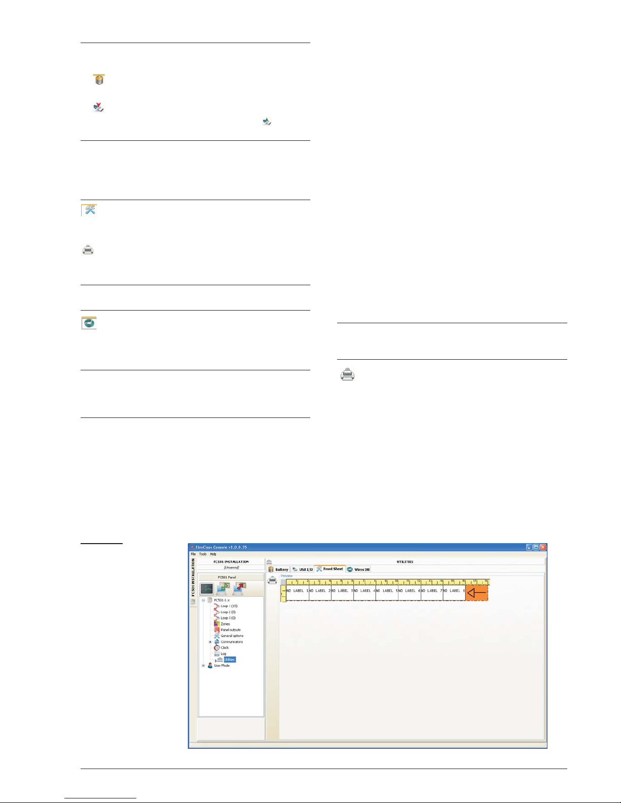
Utilities
The following functions are located on the Utilities
Page:
Ø
- checking Battery Calculations (see next dedica
-
ted paragraph).
Ø
- using a USB stick both to load the firmware,voi
-
ce messages, panel programming, then downlo
-
ad the data of a customer.
+
By clicking on "Overrride", it is possible to adjust
the panel ID for export/import. If the option "Any
Panel [XXXX]" is implemented, it is possible to utili
ze this configuration in any Panel (e.g. to load
same voice messages in several panels)
- loading the label of the first 8 zones, which should
be printed and inserted in the transparent window in the
User Interface (see Description of the parts).
- printing a pdf file which contains descriptions of the
first 8 zones. The size of the front label is predetermined
and can not be resized (see Figure 27).
+
In the Printer driver, set the “Page resizing” option
to “None"
- importing the type of wiring (from a database) for
use in various connections Loop. These type of wires
will be used in the Loop wire calculation (see same
paragraph).
+
The database can be moved from one system to another. The Console searchs for the wire database while
starting. If the user cannot access a moved database,
simply close the software and restart.
n
Battery Calculation
The Battery calculation window allows you to see (Figu
-
re 28):
Ø
the FC501 Loads,
Ø
the Loop1,Loop 2, Loop3 devices loads,
in the condition of Normal Load and Alarm Loads
(percentage of devices in alarm status), when the Ma
ins fails. Below this window, in the option “Others Load”,
if needed, the Loads on Auxliary terminals will be inser
ted. Automatically the Total Load, the Battery needed
and the Battery Recharge Time will be shown.
Set the Stand-by hours, Alarm minutes values and
the calculation will be done.
Battery calculation Parameters:
Ø
Stand-by hours (From 1 to 144 h)
Ø
Alarm minutes (From 1 to 240 m)
Battery Type: this is the battery (Ah) arising from calcu
lation.
Battery calculation constraints:
Ø
Lock stand-by hours
Ø
Lock battery type.
Lock stand-by hours: “Battery Type” value (Ah) will be
calculated, fixed Stand-by hours, Alarm minutes;
Lock battery type: “Stand-by hours” value will be cal
-
culated, fixed Battery Type (Ah), Alarm minutes.
+
The software calculation is a rough calculation and
cannot substitute the Installer and/or Qualified person calculation.
Exports the battery calculation into a .CSV file that
can be opened by Excel or a similar application.
48 Addressable Fire Panel FC501
Figure 27 Page to
print the zones label.
Page 49
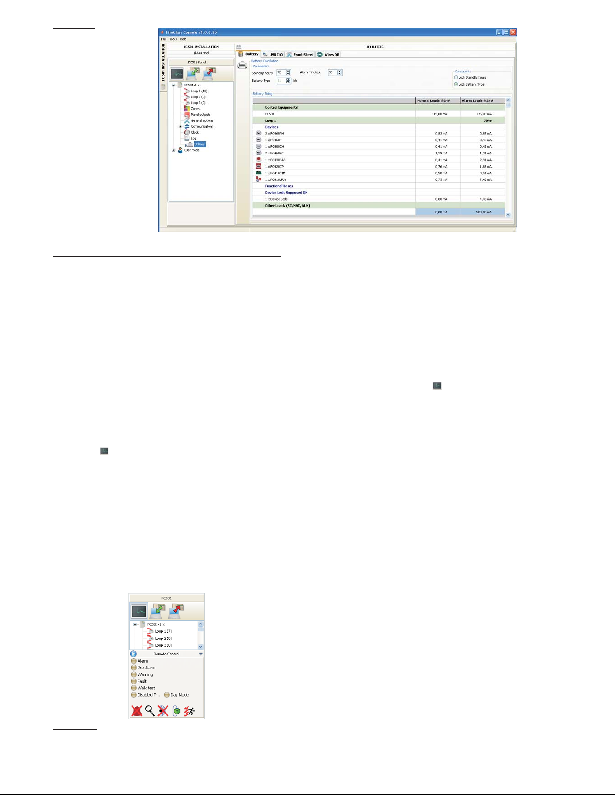
User mode
If the option "Installer Mode" is enabled, it is now possi
-
ble to program/ change the installation,using the Instal
ler password. If the option "User Mode" is enabled, this
feature allows the user to perform the real time monitoring
of the panel zones and the loop devices associated with
them. The loop device or zone is displayed in a way that im
mediately informs the user about its state with a coloured
background, an overlapped icon, etc. Selecting the loop
device, the user can also receive real time information about the last measured value (that can be expressed in °C,
ppm, %, V, etc., depending on the device type).
While the FC501 Console is running, the user can
choose whether to work in Normal mode of communication (communication with the panel takes place
only when required), or in Real Time mode.
The communication in Real Time mode is activated by
the button , and starts a session of continuous communication with the control panel.
While the FC501 Console is in Real time mode, it con
stantly receives data from the panel, and provides the
user with feedback on the changes of status of the con
trol panel. The communication in Real Time mode pro
vides the user with two additional controls: Events in
real time, and Remote control.
The Event log in real time is similar to that found in the
“Event Log” page, but it is updated constantly, and always
shows the last 16 events generated by the control panel.
The remote control panel is used to send commands
to the Fire Panel as if a graphical interface were being
used. This feature allows the user to remotely press the
functional buttons that are present on the panel user in
-
terface:Silence
, Reset, Investigation, Lamp test, Silen
ce Buzzer, Evacuate. Sending a remote command to
the panel through this interface will require the SW User
to insert the panel’s User or Installer password for secu
rity reasons.
A control keypad will request the password when commands
are sent to the fire panel. The remote control panel also
shows the detailed status of the connected fire panel, and
provides a ready visualization of status changes.
A second click on the button ends the communication in real time mode and returns to normal mode.
PC PROGRAMMING 49
Figure 28 Utilities
window
Figure 29 Remote Control display
Page 50
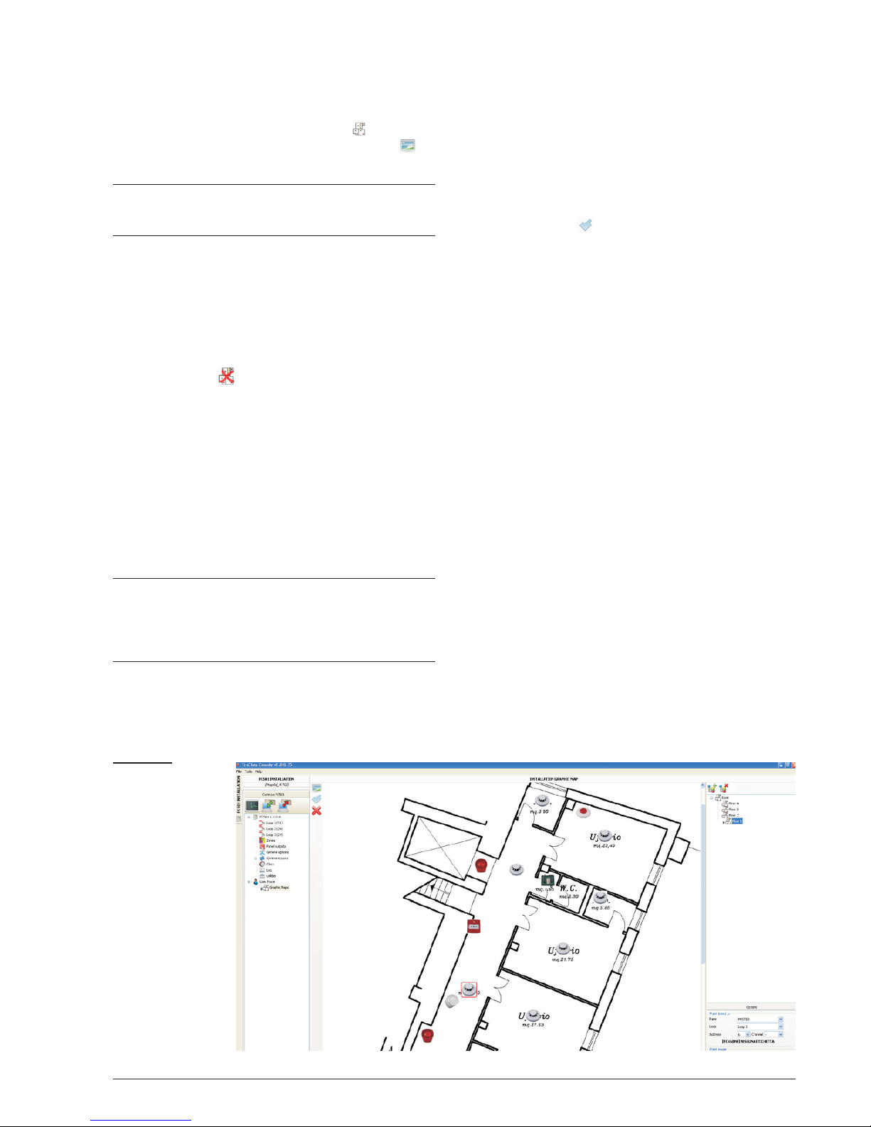
n
Graphic Maps
The User mode provides the use of Graphics Maps.
The activation procedure follows.
1. It is necessary to create the tree structure to contain
the Graphics map. Click on the icon and define
the first map/background, click on the icon ‘to
import it.
+
The system of Graphic maps allows the use of
vector graphics file (WMF) as well as the more tra
-
ditional bitmap formats (BMP, JPG, GIF, PNG).
This is the map that will be shown in the condition of ab
-
sence of events.
2. Do the same for other levels of maps and insert in
each node of the tree structure its plan (e.g. the pic
-
ture of the building, the floor where the system is in
-
stalled and the installation plan).
3. Use the icon to delete any map/structure.
4. Insert the devices on the maps; after the map has
been selected, click on the name of the installation,
in the same window, under the tree. A list of all de
-
vices on the loop will be shown. At this point it is suf
ficient to drag the selected device in the relevant
position on the map in question.
5. The final map consists of a series of separate
pages linked together and easily accessible or by
accessing to the tree diagram.
+
The Graphic Map, in Real time, is shown in a dedicated window. It is possible to analyze more than
one device at a time, but each new image requires
additional system resources. To analyze more
than four devices simultaneously is inadvisable
In Real-time mode, the Graphic map is normally shown
in stand-by status (first map/Background).
6. When the fire panel detects and reports a changed
status of detector or module, the FC501 console re
places the icon of the detector with the icon of the
event (Fire Alarm, Fault, etc.).
7. The FC501 console activates the Graphic map
where the detector/module has changed status.
Through the connection between the activated map
and the first map/background of higher level, the
area associated will blink.
8. Use the icon to realize the drawing of possible
areas, that will blink when the contained devices
will be activated. To close the area: a double click
using the Dx button.
9. Use the icon to delete any devices or areas, after
they are selected.For more info about the function
-
ing and use of Graphic maps, follow the Help, ac
cessible both by main menu and by the Graphic
maps.
n
Disable
The disable page (click the right button on the selected
device) is available only when the FC501 Console com
-
municates in Real Time.
The items that can be disabled/enabled are:
devices, zones.
Before sending a Disable/Enable command, the FC501
Console provides the prompt to enter the User password.
50 Addressable Fire Panel FC501
Figure 30 Exam
ple of the graphical
maps
Page 51

PC PROGRAMMING 51
Page 52
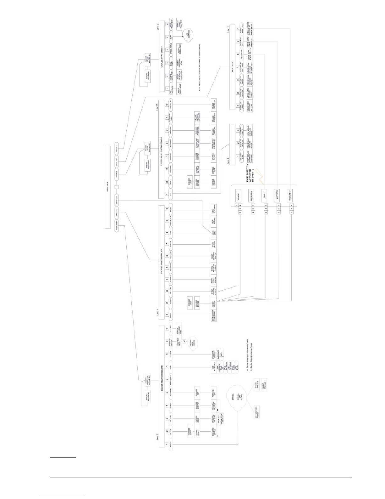
52 Addressable Fire Panel FC501
Figure 31 Diagram of all possible operations from the panel, L1, L2 and L3 Levels
Page 53
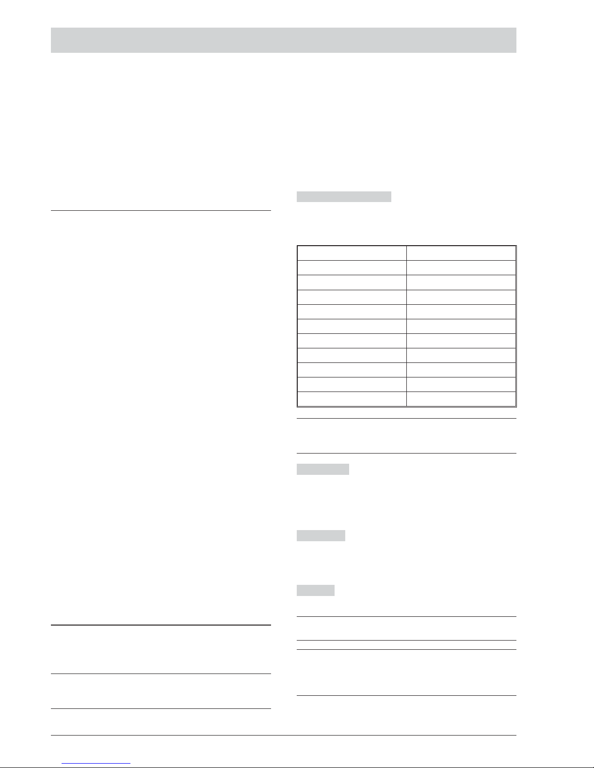
PROGRAMMING FROM THE PANEL
The following section provides an overall view of how to
use the User interface Programming (Main panel) of the
control panel. For details regarding the parameters of
each phase, refer to the respective paragraph in the
“PROGRAMMING FROM A PC” chapter.
Using the system
The FC501 system can be managed from the User in
-
terface (main panel) and/or through the FireClass Con
sole application. The User interface (main panel) allows
access to different authorized Level.
There are three different access levels which include:
L1= First Level: this level allows the Reading of Para
meters ONLY:
-ANALYZE button views the status of the: LOOP,
DEVICE, SW ZONES, OUTPUT, NETWORK,
TELECOM, OPTIONS, LOG, FW Vers., and PANEL;
-View LOG;
-View Lists button views the lists of: DIS. ZONES,
DIS. DEVICES, DIS. PARTS, WALK TEST, FAULTS,
WARNINGS and Dev. in TEST.
L2= Second Level or USER Level: access to this level
requires entry of the USER PIN (Access Level 2).
This level allows all the operations of the First Level, but
also allows you to MODIFY:
-MODIFY button for: Init MSG (MESSAGE), L2 USER
PASSWORD, DAY/NIGHT, TIME and DATE, CLEAR
LOG and WALK TEST;
-DISABLE button for: DIS LISTS, DEVICE, SW
ZONES, OUTPUT, NETWORK, COMMUNIC., FIRE
RELAY, SOUNDERS;
L3= Third Level or INSTALLER Level: access to this level
requires entry of the INSTALLER PIN (Access Level 3).
This level allows all the operations of the First and Se
cond Level, but also allows you to program the system;
the Programming phase allows the installer to program
the control panel and peripheral devices (detectors,
modules, repeater), in detail:
AUTO, DEVICES, SW ZONES, OUTPUTS,
NETWORK, MAP DEVICE, USB, SYSTEM, DEFAULT
and PWD L3.
Operating the system from the Panel
To manage the system from the User interface (Main
panel), the Alphanumeric keypad, the Cursor keys, the
ESC Key & the ENTER key are used.
+
The use of the keypad, cursor keys, ESC key &
Enter key is explained in detail in the following sec
-
tions.
n
Alphanumeric entry (Editing text)
Use the Alphanumeric keypad to create labels and en
ter data and codes.
The string must be 20 characters max.
Alphanumeric keypad Each time the alphanumeric
key is pressed in the selected position, pointed by the
cursor, the characters printed on the key will appear in
sequence and cyclically.
Key Sequence
1 ABC1
2 DEF2
3 GHI3
4 JKL4
5 MNO5
6 PQR6
7 STU7
8 VWX8
9YZblank 9
0 blank 0
+
By long pressing the "0" key, the entered data will
be cleared and the cursor will return to its starting
point.
Cursor keys
Use the UP key for upper-case letters
and the DOWN key for lower-case letters.
Use LEFT and RIGHT keys to scroll along the line,
then press the alphanumeric key to insert in the selec
-
ted position.
ENTER key Once the text has been completed, press
the ENTER key to confirm and step forward, or in the
main page signaling a local programming activity follo
-
wed by a panel reset.
ESC Key
The ESC key is used to cancel the operation
and to step back to previous page.
+
For additional functionality about the keys use, see
the User Manual, Chapter "User Interface".
+
The following pages show all possible operations
managed at Level 3 ( Installer Level).
The operation managed at Level L1 and L2 (User
Level) are shown in the User Manual.
PROGRAMMING FROM THE PANEL 53
Page 54

Assistant text composition
To make the entry of text strings easier, an assisted
procedure has been included, based on a pre-compiled
list of 128 words (18 char max) vocabulary. When one
of the numeric keys is pressed to enter a letter, the first
word in the list which begins with that letter will be inser
ted. The up and down arrow will, respectively, load the
next or the previous word in the list. This "assisted entry
procedure" is entered by keeping the UP key pressed
for more than 3 seconds, while pressing the DOWN key
for more than 3 seconds will deactivate the "assisted
entry procedure" and the normal single character entry
is reactivated (see Figure 32). When the "assisted entry
procedure" is active, the string "Vocabulary ON" blinks
on the upper right area of the LCD display. In the "Voca
bulary area" the word currently selected (row aligned
with the "Entry area") is displayed. The word that prece
des in the vocabulary is displayed in the upper row whi
le the next word is displayed in the lower row. In the
"Entry area" the words used to compose the label are
displayed. To enter a word it is necessary to press the
numeric key (more than one time if necessary) related
to the first letter of the word that needs to be entered. If
this word is not correct, it is possible to scroll through
the vocabulary using the UP and DOWN keys until a su
itable word is found. During the vocabulary scan, the
word in the middle row is entered in the "Entry area"at
the cursor position. Using the LEFT and RIGHT keys it
is possible to move the cursor to the beginning of each
word.
n Single Selection
This is normally used to select a single value between a
set (max 8) of possible values.
ON off
^
The selected value is displayed in Upper case. The selection of a further value will automatically deselect the
previous selected value. In this phase:
Alphanumeric keypad No function is related to
Alphanumeric keypad.
Cursor keys
Up key: No function is related to UP key
Down key: No function is related to Down key;
Right key: Moves the cursor to the next value position
and select the value pointed;
Left key: Moves the cursor to the previous value posi
tion and select the value pointed.
ESC Key: Use ESC key to cancel the operation and to
step back to previous page.
ENTER key: Accept the programmed string and the User
Interface moves to the next programming parameter page,
if any, otherwise returns to the main page signaling a local
programming activity followed by a panel reset.
n
Multiple Selection
This is normally used to select more than one value bet
-
ween a set (max 8) of possible values.
SUN mon tue wed thu FRI SAT
^
The selected value is displayed in Upper case.
In this phase:
Alphanumeric keypad No function is related to the
Alphanumeric keypad.
Cursor keys
Up key: select the value pointed by the
curso
r.
Down key: deselect the value pointed by the cursor;
Right key: Moves the cursor to the next value position
and select the value pointed;
Left key: Moves the cursor to the previous value posi
tion and select the value pointed.
ESC Key: Use ESC key to cancel the operation and to
step back to previous page.
ENTER key: Accepts the programmed string and the
User Interface moves to the next programming parameter
page, if any, otherwise returns to the main page signaling
a local programming activity followed by a panel reset.
n Date and Time
This is normally used to enter the time and date in the
following format:
hh: mm: ss dd/mm/yy
^
Above is the default time format. It is possible to select
an alternative time format displayed below:
hh: mm: ss mm/dd/yy
^
In this phase:
Alphanumeric keypad Used to enter date and time
numeric value.
+
Long pressing the "0" key will clear all entered data
Cursor keys
Up key: No function related to UP key
Down key: No function related to DOWN key
Right key: Moves the cursor to the next digit position;
Left key: Moves the cursor to the previous digit position;
ESC Key: Use ESC key to cancel the operation and to
step back to previous page.
ENTER key: Accept the programmed string and the User
Interface moves to the next programming parameter
page, if any, otherwise returns to the main page signaling
a local programming activity followed by a panel reset.
n
Numeric entry
Normally used for enter numeric data up to 20 digit
.
[]
^
In this phase:
54 Addressable Fire Panel FC501
DEVICE NAME
[area ] area
MS: L1 det002 Vocabulary ON
bathroom
Device coordinate
^
Cursor
Assisted procedure active
Vocabulary area
Entry area
Figure 32 Assisted entry procedure.
Page 55
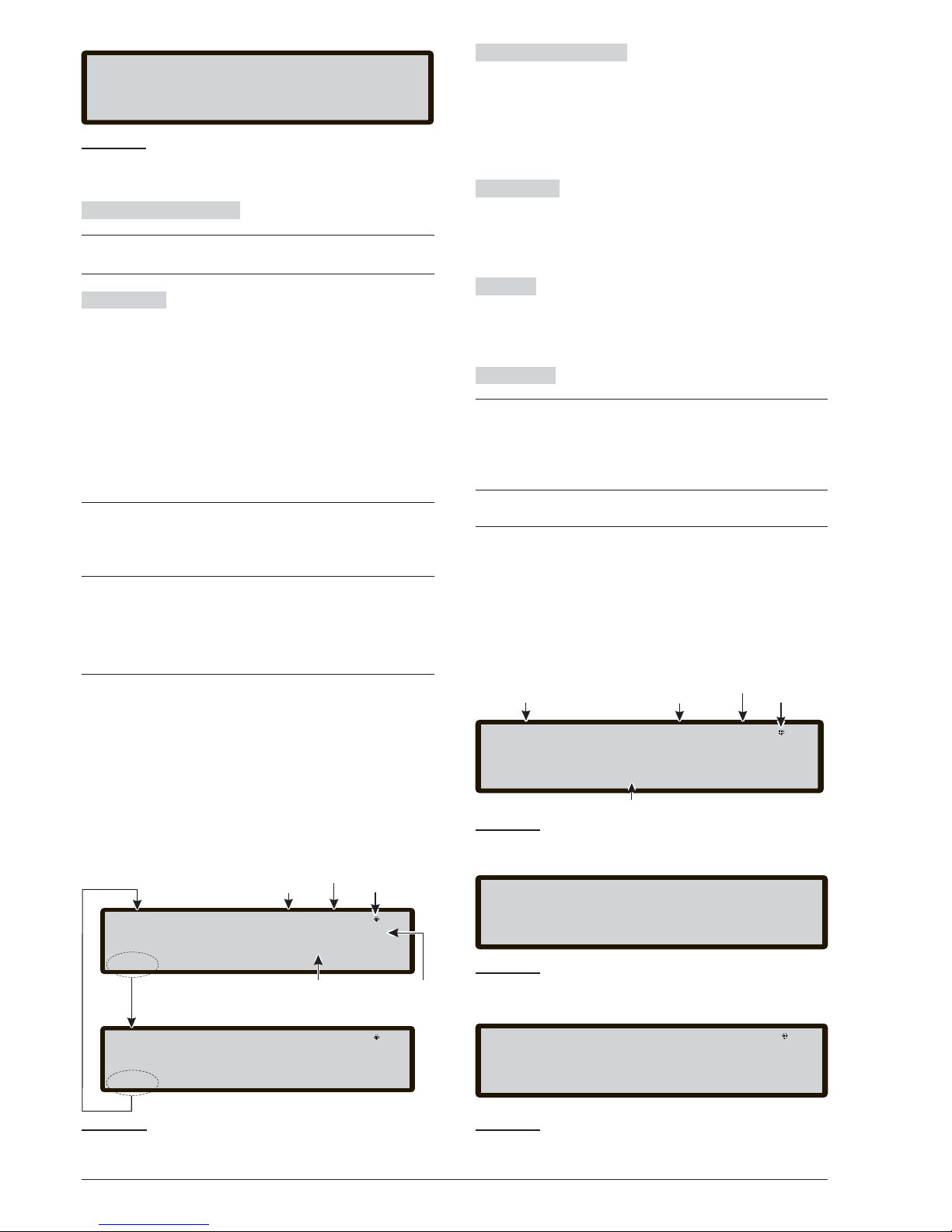
Alphanumeric Keypad
Used to enter digit
.
+
By Long pressing the "0" key, all of the entered
data will be cleared
Cursor keys
UP key
: No function is related to UP key.
Down key: No function is related to Down key;
Right key: Moves the cursor to the next digit position;
Left key: Moves the cursor to the previous digit position;
ESC Key: Use ESC key to cancel the operation and to
step back to previous page.
ENTER key: Accepts the programmed string and the
User Interface moves to the next programming parameter
page, if any is present. Otherwise the user interface re
-
turns to the main page signalling a local programming ac
-
tivity followed by a panel reset.
+
To program each parameter or option inside the
system, the same page will be used that can adapt
itself to the most appropriate program mode for the
parameter to program.
In the case of a wrong value entered, the following message will be displayed for 5 seconds (see Figure 32).
Main Page - Accessing the system
After the Control panel has been installed and powered
by the Mains, when the user accesses the panel for the
first time, they will be prompted to choose the language
of the display, then the Main Page will be shown as per
Figure 34.
In this phase:
Alphanumeric keypad
Key 1 displays the “Program”
or “Analyze” mode;
Key 2 displays the “Disable” mode or “View List”;
Key 3 shows the events of the LOG or displays the “Mo
dify” mode;
key 4 selects between groups of related functions of the
keys 1,2, and 3.
Cursor keys
The UP Key: increase the brightness of
LCD display;
the Down Key: decrease the brightness of LCD display;
the Right Key: increase the contrast of LCD display;
the Left Key: decrease the contrast of LCD display.
ESC Key Exit from the main page, moves the User
Interface to Front page or event driven page, if any. By
pressing the key for more than 3 seconds, the panel will
be forced to access level 1.
ENTER Key No function is related to ENTER key.
+
When the panel starts its normal activity and no ac
cesses to the User Interface are sensed for a period of
30s, the User Interface leaves the Main page and rea
ches the Front page. For more features see the de
scription of the MAIN page in the User Manual.
Insert password
From the MAIN page, by selecting 1 key “PROGRAM”,
the panel will prompt the Installer password to operate
at Level 3;
the default installer code is 00000: every digit will be
hidden by *(star) symbol.
in this phase (see figure 35):
PROGRAMMING FROM THE PANEL 55
WRONG VALUE
Inser the parameter again
Figure 33 Wrong value display.
1=Program lev.1 : ACTIVE
2=Disable MASTER PANEL
3=Modify SCANNING LOOP
18:50 27 - 17/10/12:
4=More
Access Level
If blinking
control panel
working properly
Current phase
Control panel status
Control Panel name
(It can be modified by User)
1=Analyze lev.1 : ACTIVE
2= ew istVi L MASTER PANEL
3=View Log
18:50 27 - 17/10/12
SCANNING LOOP
:
4=More
Figure 34 Main page window.
FC501 Panel lev.3: PROGRAM
INSTALLER
Insert the Password
[____ ]_
Name of Control Panel
Field to insert the password
Control panel
Status
Access Level
If blinking
control panel
working properly
Figure 35 Insert password (Installer code).
FIRECLASS 501
FireClass
www.fireclass.net
Figura 36 Front page window.
FC501 Panel lev.3 : PROGRAM
INSTALLER
Wrong Password
Figure 37 Display Wrong Password.
Page 56
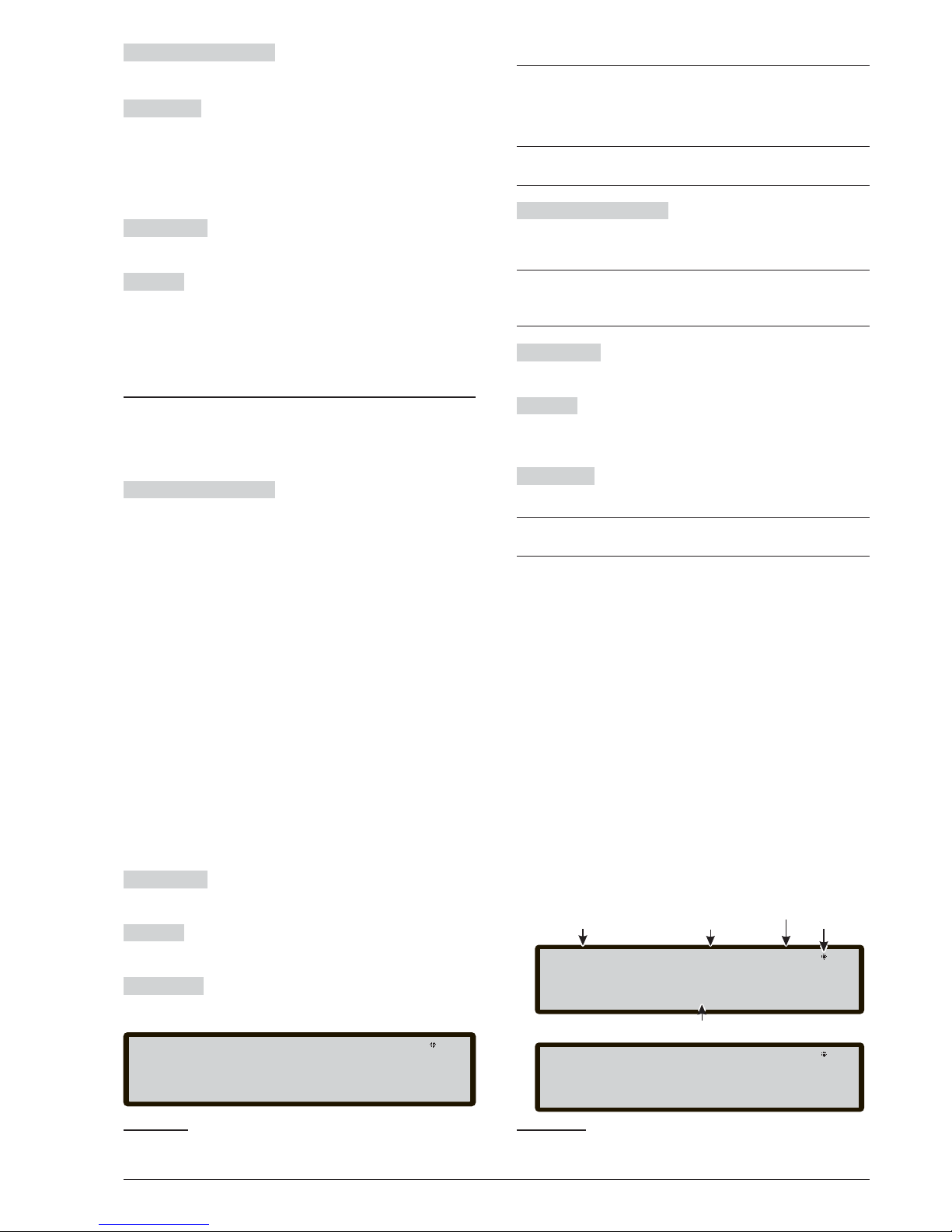
Alphanumeric keypad Use the Alphanumeric keypad
to insert the 5-digit password.
ENTER key Accepts the password and starts the pa
ssword verification process. If a Password is wrong or
missing, the screen shown in Figure 37 will appear.
To return to the previous screen, press the Esc key or
wait 5 seconds.
Cursor keys
No function is related to UP, Down,
Right and Left keys.
ESC KeyI If the entry field for the password is empty:
abort the enter password procedure and move back to
the User Interface to calling page, otherwise clear the
entered digits (clears the entry field).
Programming Page
From the MAIN page, use the 1 Key to select the Pro
gramming phase. Insert the password (installer code)
and then the page (Figure 38) is shown.
Alphanumeric keypad Use the Alphanumeric keypad
to select the different programming functions:
0= L3 PWD; start the page to insert the password of L3
level (Installer code) (see Insert-Modify password
page);
1= Auto: start the auto-learning of the loop devices and
the RS485 network devices (Repeater only).
2= FC Dev: start the selection and programming page
of the loop devices.
3= SW Zones: start the programming page of the software zones.
4=Outputs: start the programming page of the Outputs;
5= Network: start the programming page of the RS485
network, FC500MFI modules.
6=Map Device: activates the "On Demand device map
ping" feature.
7=USB: start the programming page for the manage
ment of the USB memory stick.
8=System: start the programming page of the system
parameters.
9=Default: forces a default setting restore procedure.
Cursor keys
No function is related to UP, Down,
Right and Left key.
ESC Key
Use ESC key to cancel the operation and to
step back to MAIN page.
ENTER Key
No function is related to ENTER key.
0 KEY - Insert Modify password
On the PROGRAM page, press the 0 key for the display
(see figure 39). In this phase: Installer Code at Default
is 00000; every digit will be masked by * symbol.
+
See the Installer and User features in relation to the
password.
Alphanumeric keypad Use the Alphanumeric keypad
to insert the 5 digit password. The first digit must be 0
for the installer 1 (Main Installer) and 9 for the next one.
+
The panel will verify the correct entry of the identifi
cation digit. In the case of an error, a denial tone is
generated
Cursor keys
No function is related to the UP, Down,
Right and Left keys.
ESC Key Short press: aborts the enter password proce
-
dure and moves back the User Interface to calling page;
Long press: clears all the entered digits.
ENTER key Accepts the password and starts the pa
-
ssword verification process.
+
If the password is incorrect, Figure 37 will be displayed for 5 seconds.
To avoid entering a duplicated password (two different
users/installers with the same password), the users and
installers are driven to use a specific digit as the first digit of their password. In this way the most significant digit acts as user/installer identifier.
The first digit for USER #1 is: 1
The first digit for USER #2 is: 2
The first digit for USER #3 is: 3
The first digit for USER #4 is: 4
The first digit for USER #5 is: 5
The first digit for USER #6 is: 6
The first digit for USER #7 is: 7
The first digit for USER #8 is: 8
The first digit for INSTALLER #1 is: 0
The first digit for INSTALLER #2 is: 9.
56 Addressable Fire Panel FC501
FC501 Panel lev.3 :PROGRAM
1=Auto 2=Device 3=SW Zone 4=Output
5=Network 6=Map. Dev. 7=USB 8=System
9=Default 0=L3 PWD
Figure 38 Program Page window.
FC501 Panel lev.3 : PROGRAM
INSTALLER 1
Modify any Installer Password
[_____]
Field to insert password
a)
Access Level
If blinking
control panel
working properly
Control panel status
Control Panel name
FC501 Panel lev.3 : PROGRAM
INSTALLER 1 enter the new password
enter 0 as first digit
b)
Figure 39 Insert/Modify Password window.
Page 57
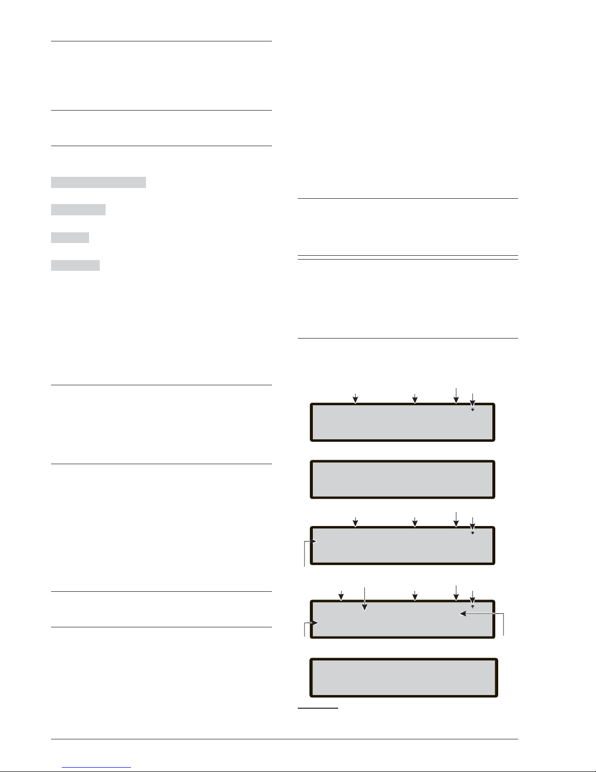
1 KEY- Auto Enrolling (Autolearning)
The Auto option from the PROGRAMMING menu will
allow you to enrol the loop devices and the RS485 net
work devices automatically (repeater FC500REP only)
The Auto option consists of three main phases: 1-Auto
enrolling, 2- Auto addressing, 3- Devices mapping.
+
Auto enrolling (Autolearning) can be done during
the installation phase and after changes of the loop
and network configurations.
Use the 1 Key to select Auto option, the display will
show Figure 40
Alphanumeric keypad No function is related to
Alphanumeric keypad.
Cursor Keys
No function is related to UP, Down,
Right, Left Key;
ESC Key
Use ESC key to cancel the operation and to
step back to MAIN page.
ENTER key
No function is related to ENTER key.
If an open circuit is detected when enrolling is launched,
the installer is prompted to launch the procedure to lo
cate the loop break. The number of devices visible on
the left and right side of the loop is calculated and di
splayed on the LCD.
If a double address fault is detected when enrolling is launched, the installer is prompted to switch on the LEDs
of the involved devices.
+
If the faults described above are generated in not
steady situations (devices which start/stop working
randomly, faulty contacts between wires, etc.) the
result of the new operations could be misleading (a
wrong number of devices on left or right side of the
loop could be signalled, the LED of a device with a
double address could remain off etc).
A new feature, "Sounders Triggered by", is available.
It allows the user to activate the sounders on the control
panel alarm or on the zone alarm by default. The enroll
procedure on the control panel LCD has a new page ad
ded to it. In this page, the installer is prompted to choo
se whether to activate the enrolled sounders on the
control panel alarm or the zone alarm.
n
Automatic zones assignment
After few seconds: the panel will prompt to choose the
type of automatic zones assignment.
+
This feature allows to assign the zone to each enrolled
detector, and define the first trigger zone for the activa
-
tion of all outputs channels in the enrolled modules.
The possible schemes used to assigned the zones are
proposed to the installer by the panel during the enroll
process (see Figure 40d):
1 = on Loop basis
2 = on device address basis
3 = no assignment.
Three different schemes are possible:
Scheme 1): all the devices located on loop1 will be assi
-
gned to zone 1; all the devices located on loop 2 will be
assigned to zone 2; all the devices located on loop 3 will
be assigned to zone 3.
Scheme 2)
From address 01 to address 16 assigned to zone 1
From address 17 to address 32 assigned to zone 2
From address 33 to address 48 assigned to zone 3
From address 49 to address 64 assigned to zone 4
From address 65 to address 80 assigned to zone 5
From address 81 to address 96 assigned to zone 6
From address 97 to address 112 assigned to zone 7
From address 113 to address 128 assigned to zone 8.
Scheme 3)
All the devices found on the loop are assigned to zone #0
(system zone).
+
The previous zone assignment schemes are also
-
applied to the first "trigger zone" in the case of out
put only devices (sounder, beacon, SNM module)
or output channel of Input/output devices.
After the Zones assignment is selected
+
For devices already addressed (1-128) the zone
assignment procedure is the same as explained
above (see Figure 40d). For not addressed devi
ces, if you choose ESC at the end of Auto addres
sing, the panel assigns the zone based on the loop,
but if you choose ENTER the panel assigns the
zone based on its address.
In this phase, the Alphanumeric Keypad only is active:
PROGRAMMING FROM THE PANEL 57
FC501 Panel lev.3: PROGRAM
ENT to view details
List of Loop with the resultpresent autoscan
Loop1=OK Loop2=OK Loop3=OK
Differences found!
b)
2 Add new devices:
3 Discard changes:
Loop= 01 lev.3: PROGRAM
Modules : 125
ENT to program devices
Num. analyzed Loop
ILoop=073 mA (400ma max)
Value of the current in the three loops,
in real time, (data are updated )every 5s
Detectors: 125
Num. detectorsfound
c)
Num.of
found modules
FC501 Panel lev.3: PROGRAM
ENROLLING IN PROGRES
a)
N.B. If the Enrolling phase finds page will be shown,
otherwise the page b)
differences, the following
PLEASE WAIT
1: Accept new configuration
Rs485net: REP.=4
Access Level
If blinking
control panel
working properly
Control panel status
Control Panel name
If blinking
control panel
working properly
Control panel status
Access Level
Control Panel name
Access Level
Control panel status
If blinking
control panel
working properly
Automatic zones assignment
1 = on loop basis
2 = on device address basis
3 = no assignment
d)
Figure 40 Autoscan results window.
Page 58
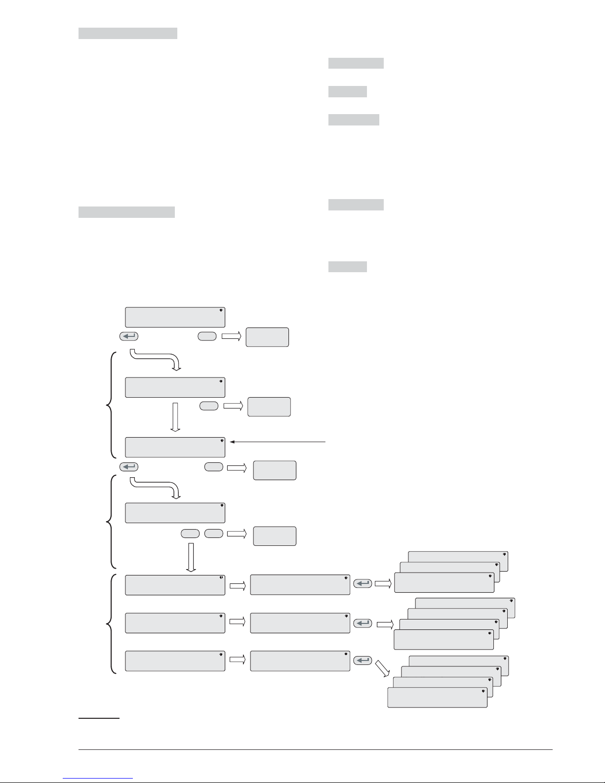
Alphanumeric keypad used to select the appropriate
zone assignment scheme 1÷ 3.
n
Sounders Triggered by
In this page, the installer is prompted to choose whether
to activate the enrolled sounders on:
1. Zone Alarm
2. Panel Alarm
n
Warning Enrolling (Autolearning)
When there are some differences between the present
configuration and that of the Enrolling (Autolearning) re
-
sults, the display will show the Figure 39b. In this pha
-
se:
Alphanumeric keypad
1 = delete the old configura
tion and accept the new one.
2 = To accept only the differences between the new and
the previous configuration detected. The new devices
will be added, while the devices that are no longer pre
sent will be removed. This applies both to the loop devi
ces and 485 network devices.
3 = The current configuration that is detected, will be di
-
scarded, the previous configuration will still be valid.
Cursor Keys
No function is related to UP, Down,
Right, Left Key.
ESC Key
Use ESC key to cancel the operation and to
step back to MAIN page.
ENTER Key
The ENTER key activates the device
details page
. The fields “Loop1”, “Loop2" and ”Loop3"
show if there are any devices connected. In both cases:
Autoscan OK or NO, it is possible to view details on the
Loop, Figure 40c). The “RS485net: Rep“ show the num
-
ber of repeaters found on the network RS485.
In this phase:
Cursor Keys
The UP key: shows information relating
to the next Loop.
The Down Key: shows the information relating to the
previous Loop.
No function is related to Right and Left Keys.
ESC Key
Use ESC key to cancel the operation and to
step back to MAIN page.
58 Addressable Fire Panel FC501
DEVICE MAPPING RUNNING 0=stop
Evt time type add counter 017
016 10:15:33 PH L1:--017 10:17:19 PH L1:---
AUTO ADDRESSING END
Found: 018 detectors, 004 modules
ENT to DEVICE MAPPING, ESC to exit
DEVICE MAPPING STOPPED 1=run
Evt time type add done:000/022
001>10:15:33 PH L1:---< enter the add.
002 10:17:19 PH L1:---
DEVICE MAPPING STOPPED 1=run
Evt time type add done:017/022
--- unique RIM L1:---< enter the add.
--- unique LPAV L2:---
DEVICE MAPPING STOPPED 1=run
Evt time type add done:001/022
001>10:15:33 PH L1:089< ENT to config.
002 10:17:19 PH L1:---
DEVICE MAPPING STOPPED 1=run
Evt time type add done:020/022
--->*active*LPSB L3:---<enter the add.
--- --:--:--LPSB L3:---
DEVICE MAPPING STOPPED 1=run
Evt time type add done:018/022
--->unique RIM L1:015< ENT to config.
--- unique LPAV L2:---
DEVICE MAPPING STOPPED 1=run
Evt time type add done:021/022
--->--:--:--LPSB L3:005<ENT to config.
--- --:--:--LPSB L3:---
EXIT
MAIN PAGE
DEVICE MAPPING PHASE
(charge of the Installer)
BASIC DEVICE
CONFIGURATION PHASE
Notes:
AUTO ADDRESSING RUNNING
PLEASE WAIT
ESC to exit
Master panel Lev.3: Program
Detector: 50 Modules: 44
Iloop=073 mA (400ma MAX)
Not addressed dev.> ENT to AUTO-ADDRESS
PANEL IS READY TO WORK
AT THIS TIME
(with the default basic programming)
MS: Det 089 lev.3 :PROGRAM
WORKING MODE Master panel
[First flo ]
^
MS: Det 089 lev.3 :PROGRAM
DEVICE NAME Master panel
MS: Det 089 lev.3 :PROGRAM
ASSIGNED ZONE Master panel
[First flo ]
^
MS: Det 089 lev.3 :PROGRAM
DEVICE NAME Master panel
[First flo ]
^
MS: Det 015 lev.3 :PROGRAM
TRIGGER ZONE EVENT Master panel
[First flo ]
^
MS: Det 089 lev.3 :PROGRAM
DEVICE NAME Master panel
MS: Det 015 lev.3 :PROGRAM
TRIGGER ZONE#1 Master panel
[First flo ]
^
MS: Det 089 lev.3 :PROGRAM
DEVICE NAME Master panel
MS: Det 015 lev.3 :PROGRAM
TRIGGER ZONE#1 Master panel
[First flo ]
^
MS: Det 015 lev.3 :PROGRAM
DEVICE NAME Master panel
[First flo ]
^
MS: Det 005 lev.3 :PROGRAM
TRIGGER ZONE EVENT Master panel
[First flo ]
^
MS: Det 089 lev.3 :PROGRAM
DEVICE NAME Master panel
MS: Det 005 lev.3 :PROGRAM
TRIGGER ZONE#1 Master panel
[First flo ]
^
MS: Det 089 lev.3 :PROGRAM
DEVICE NAME Master panel
MS: Det 005 lev.3 :PROGRAM
TRIGGER ZONE#1 Master panel
[First flo ]
^
MS: Det 005 lev.3 :PROGRAM
DEVICE NAME Master panel
[First flo ]
^
BY WALKING
(Panel +installer)
ESC
ESC
ESC
0
]
EXIT
MAIN PAGE
DEVICE ACQUIRING
(charge of the Panel)
BY DEVICE
“Unique”, in the time field, indicates that it is the only device of it's type on the loop.
For example if only one FC410DDM module is used in the system, it is tagged as “Unique”
so it is not necessary to activate it , the installer knows where it is.
“Active”, in the time field, indicates that the relevant device is active, it is applicable ONLY
to the output device type like sounders, beacons, SNM modules, etc.,
When the installer, scanning the list of previously auto-addressed devices, reaches an
output-only device type, this device becomes active (a sounder starts to sound, a beacon
starts to flash, an output module illuminates its LED) until a new device is selected or the
permanent address is entered. In this way it will be possible to locate where the device is.
EXIT
FAULTPAGE
(not addressable devices)
ESC
EXIT
FAULTPAGE
(not addressable devices)
Figure 41 Autoaddressing scheme.
Page 59

ENTER Key
The ENTER key accept the device selec
-
tion and activate the loop device programming
.
+
Attention: when the Enrolling is done, the devices
programming data (except their assigned names)
will restore to the factory defaults; therefore a pre
-
vious configuration will be lost (Selection 1).
Auto addressing procedure
Auto-addressing creates a sequence of operation that
allows to the installer to make all the devices accessible
by the panel without executing any previous configura
tion action on the devices, during their installation phase.
The installer no longer needs to use the FC490ST, the
programming Tool of the Loop devices, and conse
quently no longer needs the procedure for the manual
assignment of the devices addresses. Furthermore the
auto-addressing procedure must allow the installer to
know or set the geographical position of the devices in
the site (device mapping phase).
+
In the Program Menu of the loop devices, a new
item appears. This allows the installer to switch
on(steady)/off the device LED. This allows the in
-
staller to activate the device LED from the control
panle User Interface in order to easily identify the
device on a given field.
The Auto addressing procedure is part of the loop devices enroll process in the FC501 panel. The loop devices enroll process is initiated by the installer:
- press the 1 key to enter in PROGRAMMING mode.
Enter the Installer PIN (00000) at default. Each digit will
be masked by
* (star).
- Select option 1: AUTO.
When all the devices are initialized in Loop, the panel
will prompt the user to choose the type of automatic zo
nes assignment:
1 = according to the Loop
2 = based on the addresses of the devices
3 = do not assign
When this choice is made, the user can reach the re
sults phase by:
Ø
pressing the ENTER key to activate the
AUTOADDRESSING phase.
Ø
or pressing ESC to the FAULT page (not addressa
-
ble devices).
By default, any addressable device has the address 255.
The fire panel examines the serial number of each devi
ce and assigns each an address from 1 to 128.
If the control panel finds a device with a different address
than default (255) it leaves the address set at that device.
+
The control panel is ready to work, at this time,
(with the default basic programming)
If for requirements of the system, the installer wants to
set the system (for example set the address 1 to detec
tor 1, address 2 to detector 2, and so on), follow this pro
cedure:
Ø
press the ENTER key, so the fire panel initiates the
MAPPING DEVICES phase. First phase:
Ø
In this phase, the installer must activate in sequence,
moving in the plant, all input devices: detectors, in
put modules, Manual Call Point, and then return in
front of the fire panel.
Ø
Report the sequence of activation on the map of
system.
The fire panel will store the activation sequence
(even temporarily).
The installer using the User Interface UP and DOWN
key will start to examine the first activated device.
Ø
Select the device, the address will blink, so the instal
ler can change the address.
Press ENTER to confirm and the address will beco
me fixed.
+
If the ENTER key is pressed again, the installer can
switch to programming phase of the device in que
-
stion.
"Unique”, indicates that it is the only device of its type on
the loop. It is not necessary to activate it and the instal
-
ler knows where it is.
Second phase:
In this phase, the installer examines the sounders,the
beacons and the output module.
Ø When the installer, scanning the list of previously
auto-addressed devices, reaches an output-only device type, this device becomes active (a sounder
starts to sound, a beacon starts to flash, an output
module illuminates its LED) until a new device is selected or the permanent address is entered.
In this way it is possible to locate where the device is.
+
The enroll process does not take place until all loop
wiring troubles have been removed.
+
The auto-addressing procedure has to be used
when on the loop there are NG1 devices, otherwise
it doesn’t have effect.
+
The device mapping process does not take place
until all double address faults have been removed
PROGRAMMING FROM THE PANEL 59
Page 60
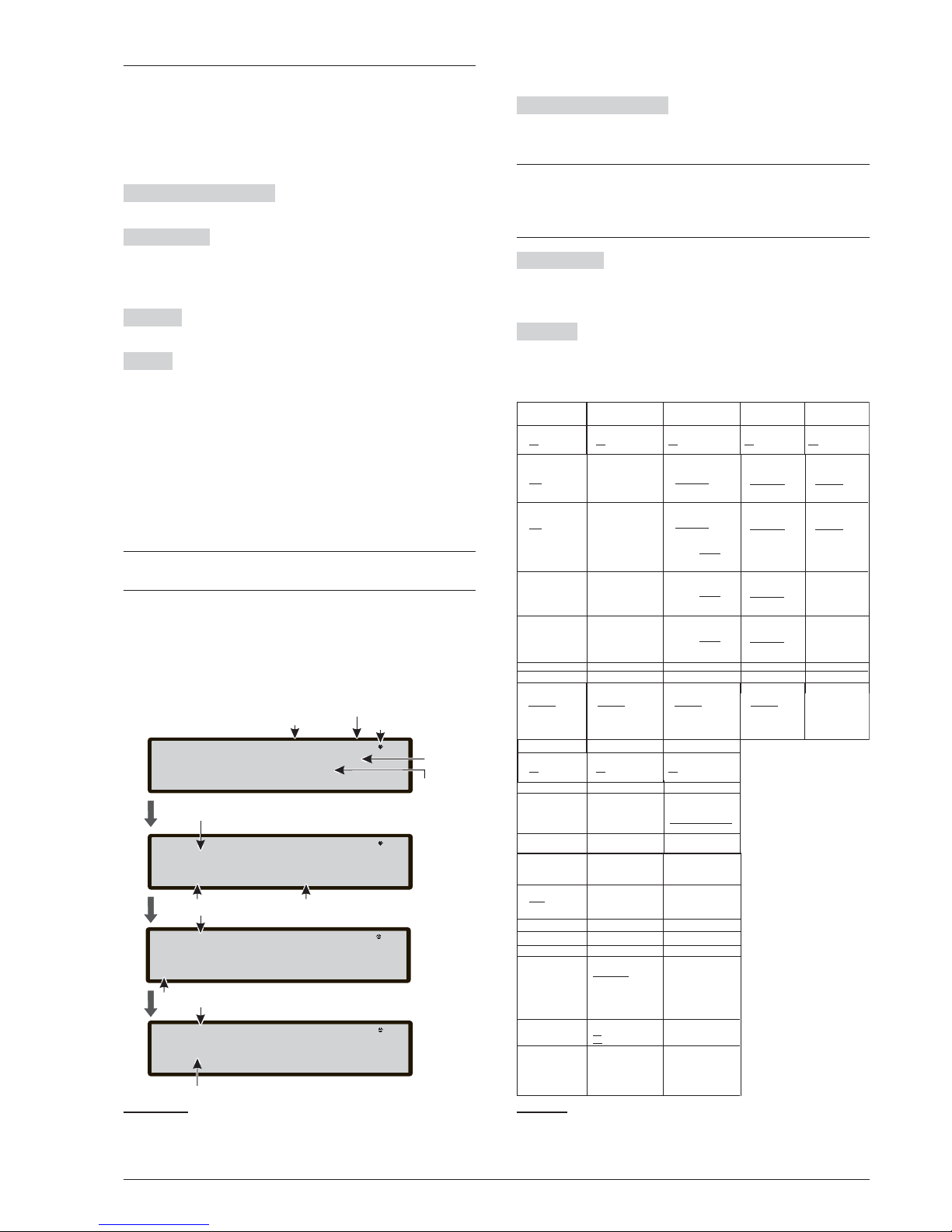
2 KEY -Device
The Device option in the PROGRAMMING menu acti
-
vates the screen used to select and program the devi
-
ces on the loops (see figure 40).
n
Choose the Loop (see User Manual View Devices)
In this phase:
Alphanumeric keypad Press 1, 2 or 3 for the relevant
loop.
Cursor Keys
No functions are related to the UP Key.
No function is related to Down Key.
The Right key selects the next available Loop.
The Left key selects the previous available Loop.
ESC key : The ESC key deletes the procedure and re
-
turns to the previous page;
ENTER The ENTER key accepts the selection and acti
vates the corresponding programming page.
Regarding figure 42, the “selected device” field shows
the currently selected device. The “Add ” field is used to
enter the address of the selected device. The scroll bar
of available devices shows the addresses and the class
of all devices configured in the selected loop.
d087 address of the device (three digits);
class of device: d = detector, m = module.
The scroll can be viewed by using the cursor keys or en
tering a device address in the “Add ” field.
+
In case the address entered does not exist, the
scroll bar moves to the next available address.
n
Choose the Device
In this phase:
Alphanumeric keypad Used to enter the address of
the selected device. if the address does not exist, the
next device available is selected.
+
If the device exists, square brackets will appear
dext to the address, but if the entered address does
not exist or is different from the one selected in the
bar below, arrows appear.
Cursor Keys
No function is related to UP or Down Key.
The Right key selects the next available device.
The Left key selects the previous available device.
ESC Key
The Esc key deletes the procedure and re
-
turns to the previous page.
60 Addressable Fire Panel FC501
FC501 panel lev 3: PROGRAM
Master Panel
[L1]L2
Choose loop Loop 1
Name
selected
loop
FC501 Panel lev 3 : PROGRAM
FC501 Panel
d001 [d187] m250
Programmed
address
Loop 1
Add=<123>
400PH
Selected address Selected device
MS:L1 det001 lev 3 : PROGRAM
FC501 Panel
Detector
to program
[Temperature]
Device name
Parameter to program
Name of
Control Panel
Control panel
Status
Access Level
If blinking
the panel works
properly
Detector
MS:L1 det001 lev 3 : PROGRAM
FC501 PanelREMOVE DEVICE?
Select
NO yes
^
Figure 42 Pages of Selecting and programming Devi
-
ces on Loop.
Heat
detector
Smoke detector
Smoke +
Heat detector
Heat+Smoke +
CO detector
Working mode:
DAY:
Working mode:
DAY:
Working mode:
DAY:
CR
A1R
A2S
Temp= A2S
A1R
DIS
High Immunity
Universal
Detector label Detector label Detector label Detector label
Assigned zone Assigned zone Assigned zone Assigned zone
Callpoint DDM Module
Detector type
Channel to
program
Callpoint label Module label
CNV conventional
GSI 4-20 mA sink
GSO 4-20 mA source
Generic digital
output channel
(loop devices)
DDM input channel
Working mode:
BNO
CNO
CNC
Input label Output label
Assigned Zone Trigger Zone # 1
Trigger Zone # 2
Trigger Zone event
ALA Alarm
DLY Delay to alarm
WAR warning
FAU fault
TST Test
DK Double Knock
Channel to
program
Generic digital
input channel
(loop devices)
Input label
Assigned Zone
Detector base
Standard
Isolator
Relay
Sounder
Addressable
Detector base
Standard
Isolator
Relay
Sounder
Addressable
Detector base
Standard
Isolator
Relay
Sounder
Addressable
Heat +
CO detector
Working mode:
DAY:
Enhanced
Disabled
CO=Default
Detector label
Assigned zone
Detector base
Standard
Isolator
Relay
Sounder
Addressable
Remove device?
Yes
No
Remove device?
Yes
No
Remove device?
Yes
No
Remove device?
Yes
No
Remove device?
Yes
No
Working mode:
NIGHT:
Working mode:
NIGHT:
Working mode:
NIGHT:
CR
A1R
A2S
Temp= A2S
Default
A1R
DIS
Smoke=
Enhanced
Disable
High Immunity
Universal
Working mode:
NIGHT:
Enhanced
Disabled
CO=Default
Working mode:
DAY:
Smoke=
Enhanced
Disable
Default
Working mode:
DAY:
Temp= A2S
A1R
DIS
Working mode:
NIGHT:
Smoke=
Enhanced
Disable
Default
Working mode:
NIGHT:
Temp= A2S
A1R
DIS
Generic Module
Remove device?
Yes
No
Remove device?
Yes
No
Remove device?
Yes
No
Module label
Assigned zone
Silenceable
On
Off
Trigger Zone # 3
Trigger Zone # 4
Trigger Point # 2
Trigger Point # 1
Trigger Point # 3
Table 9 Values table of the programming devices
Note: The underlined options are the default options.
Page 61
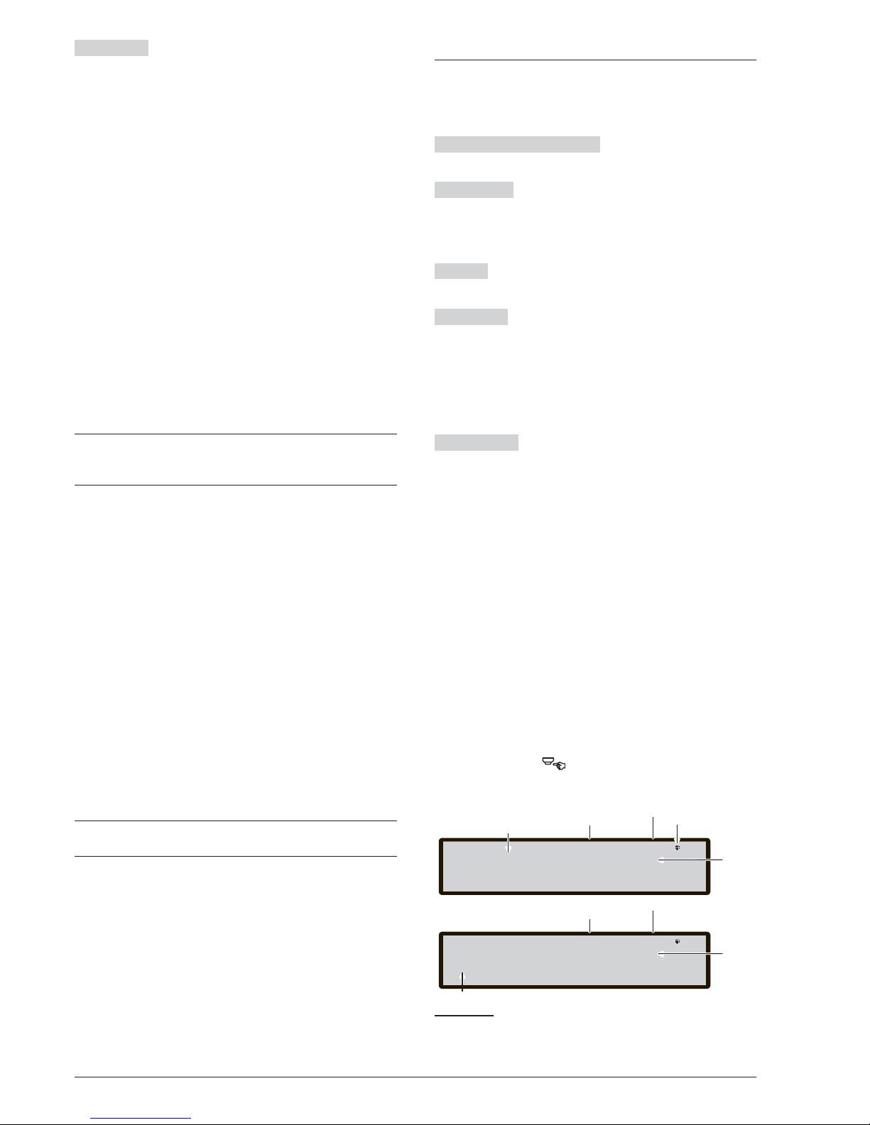
ENTER Key
The ENTER key accepts the selection
and activates the corresponding programming page.
n
Loop devices programming page
After selecting the Loop and the device, (see the Figure
42) the option "LED(skp=skip test)" is displayed.This
option allows for the location of the selected device in
the site, lighting its LED when the option "ON" is selec
ted (note that the ENTER key has to be pressed to
make the selection valid). If the device has no LED, its
sounder or beacon will be activated. The option "OFF"
removes the device signalling. The option "SKP" exits
the feature and moves to the normal device program
ming sequence where it is possible to program various
parameters relevant to the type of device. See Table 7.
Remote LED After other parameters, it is possible to
enable the activation of programmable Remote LED of
the detectors. The detectors have an output used to dri
ve the remote LED. This output is activated only for the
detector alarm to which it belongs. Now, it is possible to
program it to activate for other events, exactly as it hap
pens for the other panel outputs, as well as for the de
tector alarm to which it belongs.
+
With this option (Remote LED), it will be possible to
also program on FireClass Console, in the pro
-
gramming page of the detectors.
Separated programming of the Sounder and Beacon
When one of the following devices is selected:
FC410LPAV (all versions)
FC430LPASB
FC430SAB (with FC430SB),
In addition to those certified EN54-23:
FC410LPS-R/W
FC410LPBS
FC430LPBSB,
In the programming menu, it will be possible to choose
which channel (Sounder or Beacon) to be program
med. The User interface will ask the installer, before the
alarm conditions:
"SOUNDER = BEACON"
"yes no"
If the installer chooses "yes", the alarm conditions are
selected (and applied to both channels), otherwise the
channel selection will be displayed (therefore the alarm
conditions are valid for the selected channel).
+
See "PC PROGRAMMING" FireClass Console para
-
graph "Output module parameters programming"
3 KEY - SW zone
The SW zone option in the PROGRAMMING menu ac
-
tivates the screen used to select and program the Sof
-
tware zone (see figure 41).
The Alphanumeric keypad The Alphanumeric key
-
pad is used to select the zones number (ID).
Cursor Keys
No function is related to UP and Down
Keys.
The Right key selects the next available SW zone.
The Left key selects the previous available SW zone.
ESC key
The ESC key deletes the procedure and re
-
turns to the previous page.
ENTER Key Accept the SW zone selection and activa
te the loop device programming page, if the SW zone
exists, otherwise the following warning page is displa
yed for 5 seconds: "WRONG VALUE! enter the para
meter again".
After 5 seconds the User Interface returns to the cho
sen SW zone pages.
ZONE NAME It is possible to enter the zone label (20
characters maximum) using the alphanumeric entry
(editing text) procedures.
n SW zone in WALK TEST
After selecting the SW Zone, you can able to enable or disable the option Zone in WALK TEST (OFF) or not (off).
Ø if the option All Devices (ALL) is selected, all the de-
vices assigned to zone in WALK TEST mode, will
NOT generate alarm in the case of their activation
but they will reach the TEST status.
Ø If the option detector (DET) is selected, only the de-
tectors assigned to zone in WALK TEST mode, will
NOT generate alarm in the case of their activation
but will reach the TEST status.
Ø
If the option call points (CP) is selected, only the
call-points assigned to zone in WALK TEST mode,
will NOT generate alarm in the case of their activa
tion but will reach the TEST status.
The presence of a zone in WALK TEST mode is si
gnalled by the TEST yellow LED on the User
PROGRAMMING FROM THE PANEL 61
FC501 Panel lev.3: PROGRAM
Master Panel
Enter the SW zone number
If blinking
the panel works
properly
SW zone: 032
Index of
SW zone program
SW zone lev.3: PROGRAM
Master Panel
On OFF
ZONE IN WALK TEST
Choose between the two options
a)
b)
Control panel
Status
Access Level
Control panel
Status
Access Level
Name of
Control Panel
Name of
Control Panel
Figure 43 Pages of Selecting and programming of SW
zones.
Page 62
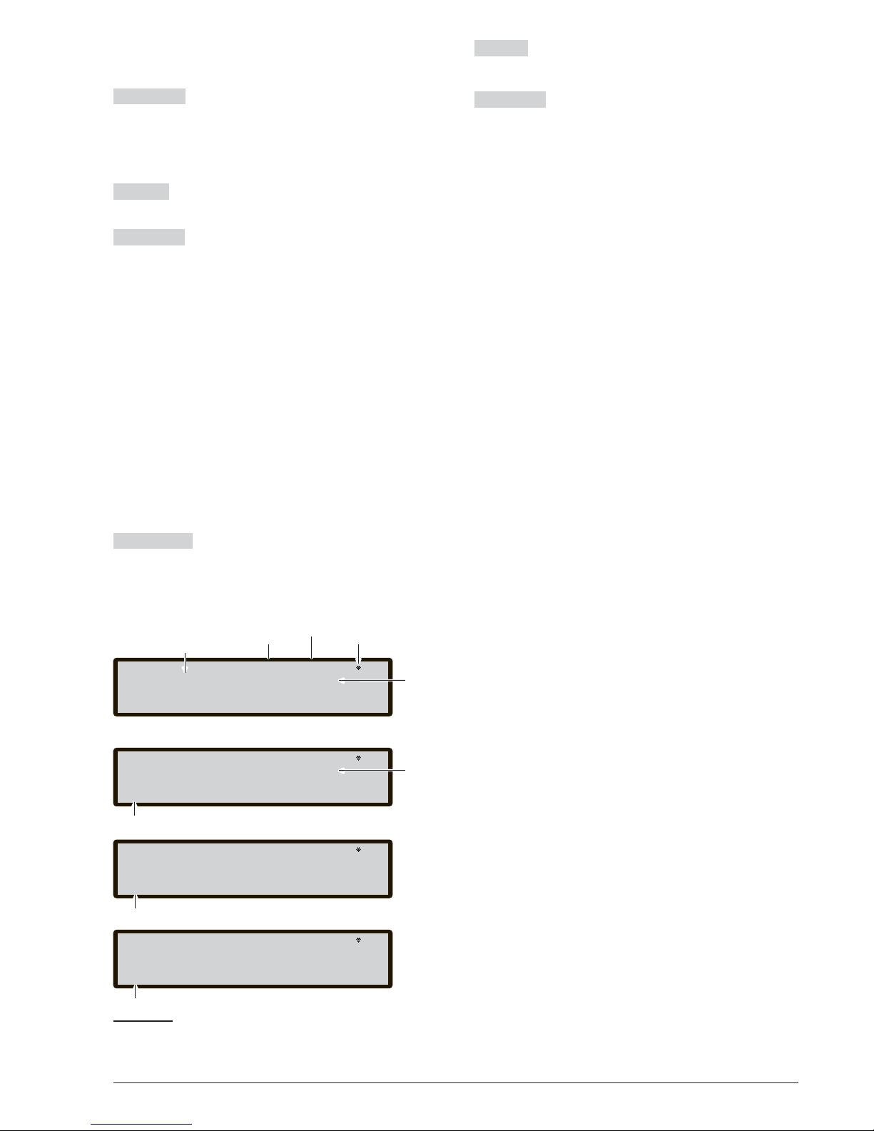
Interface. More than one zone can be put in WALK
TEST mode at the same time.
Cursor Key
No function is related to UP and Down Keys.
The Right key: selects the following ON
-OFF-ALL-det-cp.
The Left key: selects the previous
ON-OFF-ALL-det-cp.
ESC Key
ESC key deletes the procedure and returns
to the programming page.
ENTER key The ENTER key accepts the selection
and activates the corresponding programming page
n
Sounders on (3s)
If YES, every test event (input activation) activates the
sounders in the same zone for 3 seconds.
n
Smoke delay (60s/30min)
For each zone, it is possible to program the delayed ac
tivation of smoke detectors, according to the following
schedule:
when the smoke level exceeds the alarm threshold, the
panel does not signal anything at first;
- after 60 seconds if the smoke level is still above the
threshold, the system goes into alarm condition, other
wise there are no signals;
- within 30 minutes, a new alarm of the same detector or
activation of another sensor in the same zone causes
the alarm of fire panel.
Cursor Keys
No function is related to Up and Down
keys.
Use the Right and Left keys to select: On-OFF.
ESC key
Use the ESC key to delete the operation and
to step back to previous page.
ENTER key
Use the ENTER key to accept the selec
-
tion and activate the programming page.
n
Delay to Alarm
For each zone, it is possible to program the activation of
a common delay to alarm delay ( 9 minutes.). The pro
cedure is the same as the previous parameters and
also the functionality of the Cursors, Esc and Enter key
is the same (see figure 44d).
n
DLY ALARM TIME (min)
If ON is selected for the option Delay to Alarm it will be
possible to enter the zone relevant delay to alarm time.
The possible value ranges from 0 (no delay) to 9 min
utes. The value may be incremented or decremented in
steps of 1 minute using the UP or DOWN keys.
62 Addressable Fire Panel FC501
FC501 Panel lev 3: PROGRAM
Master panel
Enter the SW zone number
Access Level
Control panel
status
SW Zone: 032
SW Zone Index to
program
SW Zone lev 3: PROGRAM
Master Panel
On OFF
ZONE IN WALK TEST
Select the option
a)
b)
Name of
Control Panel
Name of
selected
Control Panel
SW Zone lev 3: PROGRAM
Master Panel
On OFF
SMOKE DELAY (60s/30m)
c)
^
Select the option
^
If blinking
the panel works
properly
SW Zone lev 3: PROGRAM
Master Panel
On OFF
DELAY TO ALARM
Select the option
^
d)
Figure 44 Page of programming option delay Detector
alarm verification.
Page 63
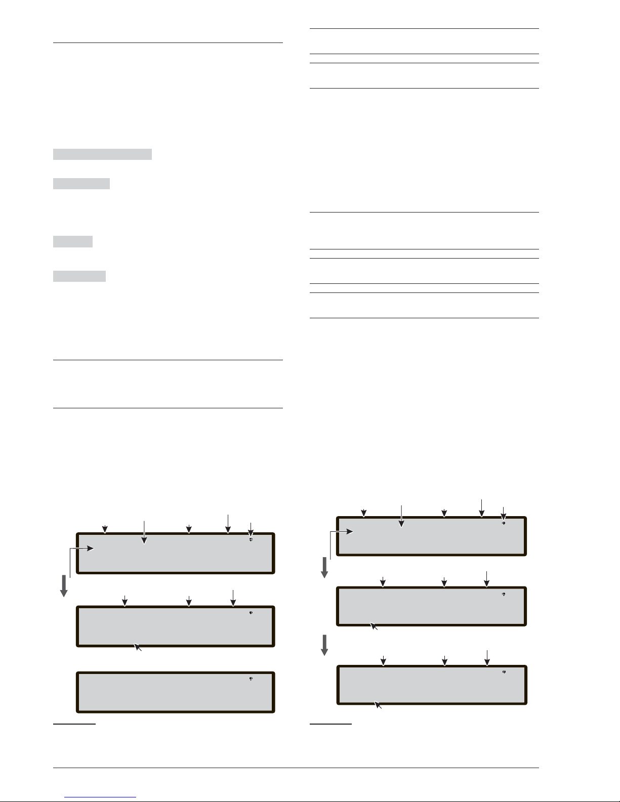
4 KEY- OUTPUT
The Outputs option, KEY 4 in the PROGRAMMING
menu, activates the panel on the board output program
ming screen. It is used to select the type of panel on the
board output, followed by the programming procedure
for that output.
n
Choose Output
In this phase:
Alphanumeric keypad The Alphanumeric keypad is
used to enter the number of SC output.
Cursor Keys
The UP Key: shows the next output cate
gory (SC-OC).
The Down Key shows the previous output category.
Right and Left keys: no functions is related to these keys.
ESC Key
Use ESC key to cancel the operation and to
step back to previous page.
ENTER Key Use the ENTER key to accept the selec
tion and activate the output selection and activate the
loop device programming page if the output exists, ot
herwise a warning page is displayed for 5 seconds.
"WRONG VALUE! enter the parameter again"
After 5 seconds the User Interface moves back to the
page for selecting the outputs.
+
Once the Output has been programmed (type and
identification number) and the ENTER key is pressed to accept the selection, enter the label for that
output.
n SET AS SC1
When set as yes the relevant output will behave as the
SC1 (Sounder Circuit 1). This allows redundant output
circuits to drive site sounders (by default set to no).
+
Setting the option to yes will end the programming
sequence for that output.
+
The panel on board Open Collector outputs (OC1,
OC2) may not be programmed to ACT AS SC1
n
PANEL ALARM TRIGGER?
When this option is set to yes (default), the relevant out
-
put becomes active on the panel alarm condition, other
wise a more specific trigger condition may be defined
for that output.
n
DISABLEMENT TRIGGER?
This option activates the relevant output if any system
part is disabled (by default set to no).
+
This parameter is made available only if the para
-
meter PANEL ALARM TRIGGER?, for the same
output is set to NO.
+
Setting the parameter to YES will end the program
-
ming sequence for that output.
+
Outputs which have this option programmed, will
not be silenceable.
This feature is also available for Panel FIRE relay and
FC410RIM, FC410SIO, FC410MIO, FC410QMO,
FC410QRM, FC410QIO loop modules.
Further parameters which can be programmed via the
panel’s User Interface include:
Ø OUTPUT NAME
Ø TRIGGER ZONE 1
Ø TRIGGER ZONE 2
Ø TRIGGER EVENT
Ø SILENCEABLE
Ø MONOSTABLE
PROGRAMMING FROM THE PANEL 63
FC501 Panel lev. 3: PROGRAM
SC Output: 001
Control Panel name
Access Level
Outputs type
Output
Number
SC Output 001 ev.l 3 :PROGRAM
[]
OUTPUT NAME
Insert Output label
Up or Down to select the type
Enter the SC Output number
Control panel
Status
Access Level
Control panel
Status
Output
Number
Enter the parameter again
WRONG VALUE!
If blinking
the panel works
properly
Figure 45 Pages for programming "SC active on disa
-
blements" option.
FC501 Panel lev. 3: PROGRAM
SC Output: 001
Control Panel name
Access Level
Outputs type
Output
Number
SC Output 002 ev.l 3 :PROGRAM
[]
^
OUTPUT NAME Master Panel
Insert Output label
Up or Down to select the type
Enter the SC Output number
Control panel
Status
Access Level
Control panel
Status
Output
Number
If blinking
the panel works
properly
SC Output 02 lev 3 :PROGRAM
Output type
on OFF
^
Select on or OFF
SC on DISABLEMENT Master Panel
Access Level
Control panel
Status
Figure 46 Pages of Selecting and programming SC
active on disablement.
Page 64
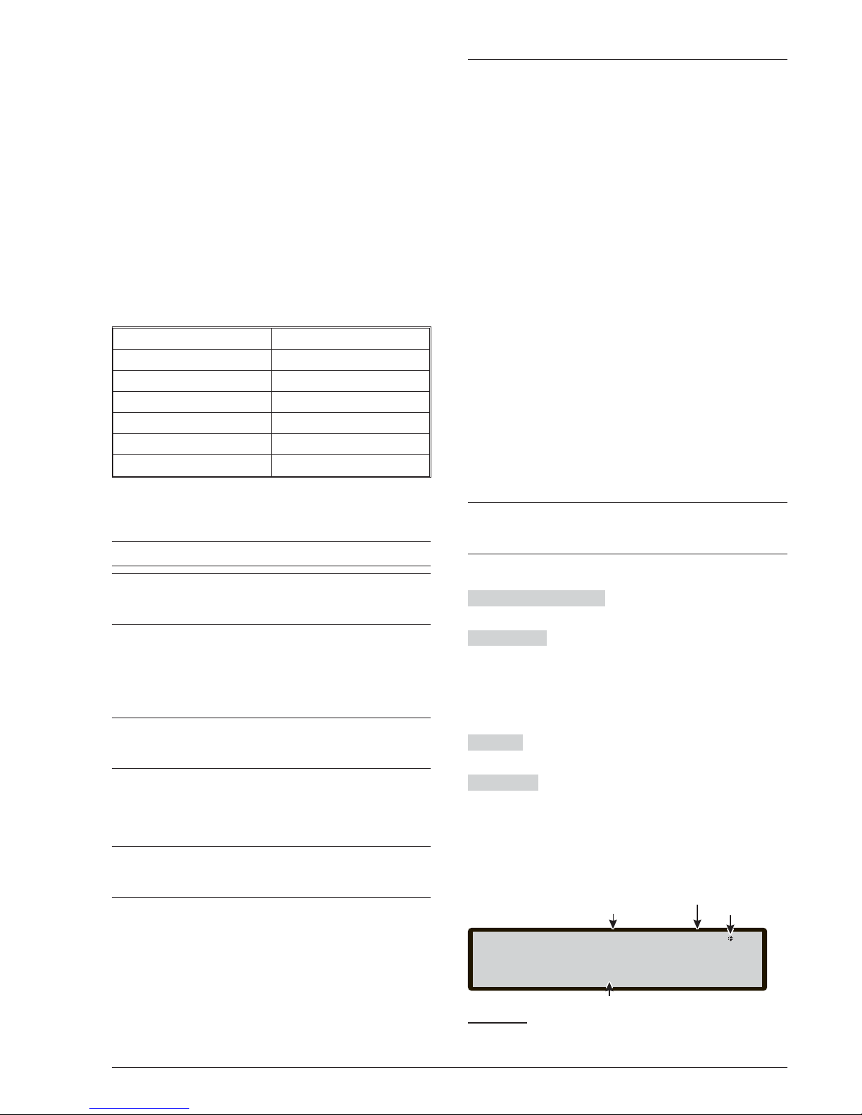
OUTPUT LABEL - enter or modify the relevant output
label using alphanumeric entry mode, 20 characters
maximum.
TRIGGER ZONE 1 - select the first zone on which
events, defined later, the output will become active. The
entry "0000" means "No Zone". Numeric entry mode,
range from0-32.
TRIGGER ZONE 2 - select the second zone on which
events, defined later, the output will become active. The
entry "0000" means "No Zone". Numeric entry mode,
range from 0 to 32.
TRIGGER EVENT - define, for both trigger zones, the
event types valid to activate the relevant output.The
event types are coded as follows:
CODE EVENT TYPE
ala Alarm
dly Delay to Alarm
war Warning
fau Fault
tst Test
dk Double Knock
You can select more than one TRIGGER EVENT (multiple selection mode)
+
The selected events are valid for all trigger zones.
+
When zones trigger condition act in "OR" mode, it
is sufficient that the trigger condition of a single
zone is matched to activate the output.
SILENCEABLE - select if the output stays active until
the SILENCE /RESOUND SOUNDERS button is pres
sed (on option set) or stay active until the RESET button
is pressed (off option set).
+
In the case of "silenceable outputs", once silenced,
it may be reactivated by pressing the
SILENCE/RESOUND SOUNDERS button again.
MONOSTABLE - allows the relevant output to automa
tically deactivate when the MONOST. OUTPUT TIME
elapses. Set this to ON to enable this feature.
+
The MONOST.OUTPUT TIME is set in the
SYSTEM section of the PROGRAM menu and its
value is valid for all outputs.
5 Key- Network
The Network option of Programming menu activates
the procedure to configure the modules FC500MFI.
When all the Control panels and the FC500MFI modu
les are connected in the Network,
1- use the 5 Key to select Network, from Programming
page in the User interface
2- the display in Figure 47 will be shown.
3- moving with the arrow keys to select the FC500MFI
module to be configured ï or ð (the symbol ^ under
the name show the selected module),
enable a FC500MFI module by the arrow ñ or disable it
by the arrow ò:
The module name will appear in uppercase if enabled.
Press the Enter key to confirm.
In the ANALYZE status (L1 level): to display the related
status is used an acronym. The acronyms are:
" OK!", The net. device is sensed as connected and
working;
" ko!", The net. device is sensed as not connected
" FAU", The net. device is faulty
" DIS", The net. device is disabled
" -- ", The net. device is not configured in the network
" OLD", The net. device has an obsolete FW version.
+
For an explanation of the features and programming (addresses), see the dedicated manual of the
FC500MFI module.
In this phase:
Alphanumeric keypad No function is related to the
Alphanumeric keypad.
Cursor Keys
The Up key enables the selected modu
le (e.g. ON1-uppercase).
The Down key disables the selected module (e.g.
on1-lowercase).
Use the Right key to select the module.
Use the Left key to select the module.
ESC Key
Use ESC key to abort the programming pro
cedure.
ENTER key
Use the ENTER key to confirm the pro
gramming procedure and to leave the page.
64 Addressable Fire Panel FC501
System lev3. : PROGRAMMING
FC500 MFI MASTER Panel
on1 on2 on3 on3
^
Symbol show the selected module to enable
If it blinks the panel
is operating normally
Access Level
Control panel
Status
Figure 47 Display to enable the FC500MFI module.
Page 65
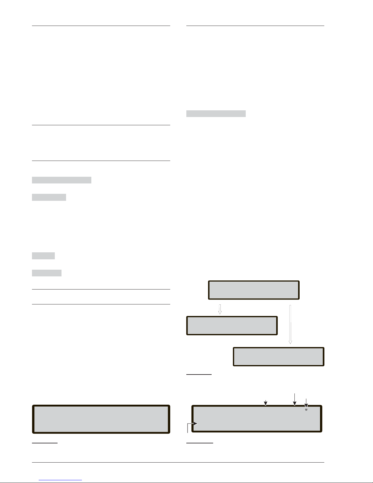
6 KEY - MAP DEVICE
This option activates the "On Demand device mapping"
feature to modify the devices addressing scheme in a
working system. In a system where the addressing
scheme is well known because all devices are singu
-
larly addressed via Service Tool or via the "device map
ping" feature embedded in the loop enroll process (1
KEY). This means that this new feature is not intended
to acquire new devices on the loops (for this purpose
the Enroll feature have to be used).
In contrast to the "device mapping" feature embedded
in the loop enroll process, the "On Demand" version will
not automatically modify: devices labels and assigned
zone.
+
All the devices, comprised also the "unique" types
will put in the "activated list". The "only output" type
devices are treated as in the standard device map
-
ping procedure (they will be singularly activated
when selected in the list).
In this phase:
Alphanumeric keypad The Alphanumeric keypad is
used to enter the new address value: 0-9;
Cursor Keys the UP key, Short press: to scroll to the
previous event in the list, Long press: to start the automatic scroll of the previous event in the list.
the Down key, Short press: to scroll to the next event in
the list, Long press: to start the automatic scroll of the
next event in the list.
The RIGHT key: to program the selected device.
The LEFT to continue the mapping procedure.
ESC key The ESC key: to end the mapping procedure
and exit.
ENTER key the ENTER key: to confirm the entered address value.
+
To stop the automatic scroll, short press of the UP
or Down key.
7 KEY -USB
The option USB in the PROGRAMMING menu activa
tes the USB programming page. 7 Key is used to select
USB programming page, Figure 50 shows:
0) Extra
1) Load Audio
2) Save Audio
3) Load programming
4) Save programming
5) FW Upgrade
6) Save LOG.
In this phase:
Alphanumeric keypad Allows the selection of USB
activities.
0) While the panel is running, it will be possible to load
the two languages present in the USB key flash me
mory (previously downloaded from the CD supplied
with the panel or from the FireClass site), see the dia
gram of operation in figure 46.
1) To load, from USB pendrive to panel, the AUDIO file
containing the voice messages.
2) To save, from the panel to USB pendrive, the curren
te AUDIO messages.
3) To load, from USB pendrive to panel, the program
ming data (*).
4) To save, from panel to USB pendrive, the current pa
nel programming data.
5) To upgrade the panel Firmware from USB pendrive (**)
(***).
6) To save the current LOG data in the panel from panel
to USB pendrive.
PROGRAMMING FROM THE PANEL 65
Device Mapping
001> 00: 19.50 P L2:001< enter the address
Evt Time Type add done 000/002
002 00: 19.50 PH L1:
Figure 48 Display "on demand device mapping".
USB activity
Example of USB activity
IN PROGRESS
Wait please
LOAD Audio
USB activity
DONE!
LOAD Audio
USB activity
FAILED!
LOAD Audio
ESC= EXIT
ESC= EXIT
Figure 49 Example USB activities.
FC501 Panel lev.3 : PROGRAM
Activities
1=Load Audio 2=Save audio 3=Load program
USB activities
4=Save program 5=FW Upgrade 6=Save LOG
0=Extra
Access Level
Control panel
Status
If blinking
the panel works
properly
Figure 50 Page of USB activities.
Page 66
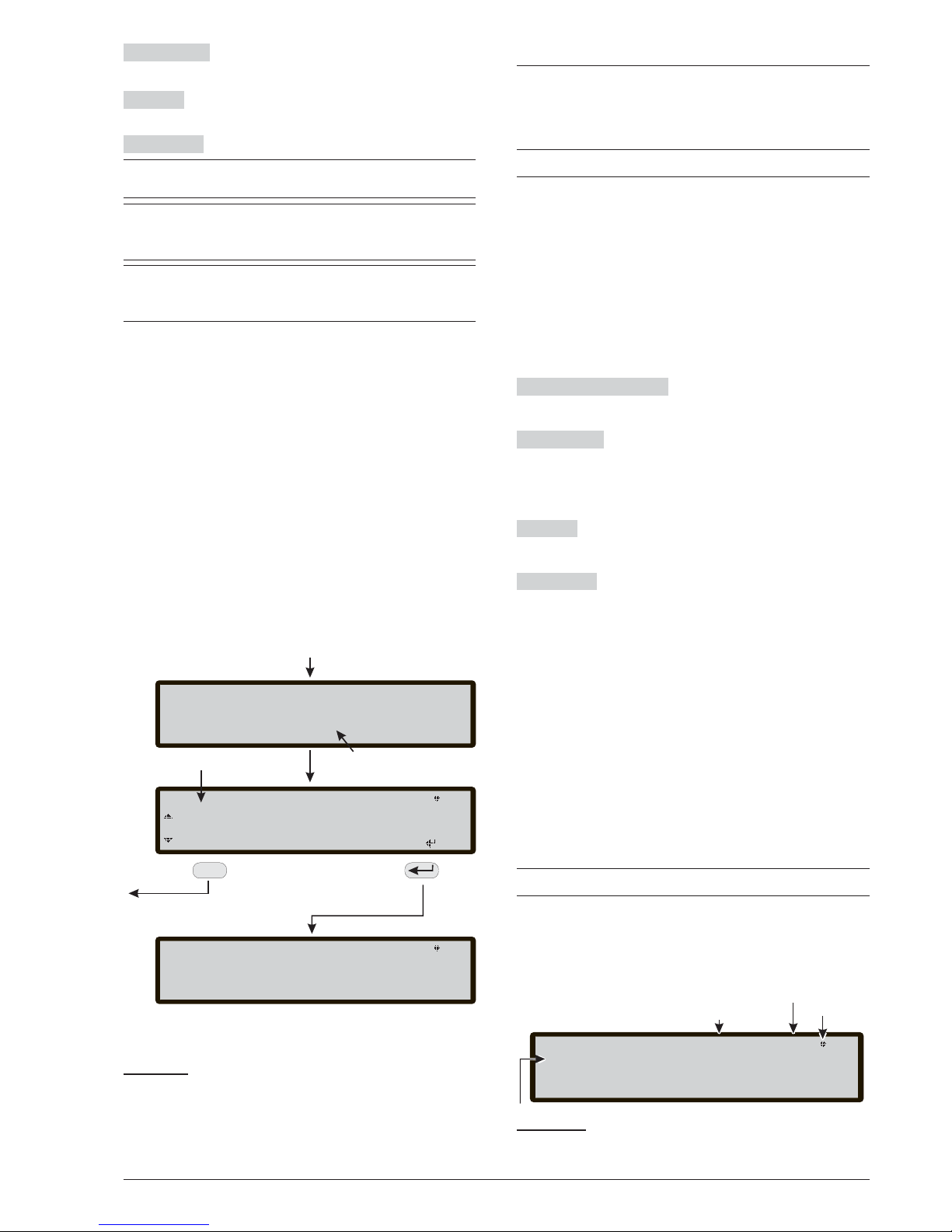
Cursor Keys
No function is related to UP, Down,
Right and Left Keys.
ESC Key
The ESC key is used to exit from the USB
activity result page.
ENTER Key
No function is related to the ENTER Key.
+
(*) The loaded data will overwrite the current data
in the panel.
+
(**) The file containing the expected FW version to
upgrade the panel has to be present in the F_fw di
-
rectory in the pendrive.
+
(***)To do the firmware upgrade of the FC500 Re
peater and the MFI module is not possible using
the USB pendrive.
In reference to the point 0) "EXTRA", at the first panel po
-
wer-up and/or at the end of the FW upgrade process of
the control panel, only a language can be loaded overwri
-
ting the second languages previously present (the first will
be the English). The available language will be contained
in a file of a dedicated folder on a USB stick connected to
the control panel before first Power up.
This loaded language will be the language of the control
panel. If the USB stick is not present at the first panel
power-up, the system will propose the default langua
-
ge: Italian and English (see figures 51, 52).
In the case of FW UPGRADE of the control panel, at the
end of the FW upgrade process, the panel will start the procedure "Language strings download via USB key at the first
panel power-up", (see figure 52) in order to load the correct
version of the required language.
8 KEY -SYSTEM
The option SYSTEM in the programming menu activates
the system language selection page (Display language:
see figure 51).
+
Other languages can be loaded from software
After selecting the language, it is possible to program:
-PANEL ID
-PANEL TYPE (FC501-L/FC501-H)
-BATTERY TYPE (7Ah/12Ah/38Ah)
-DAY/NIGHT MODE or AUTO
-DELAY TO ALARM TIME.
-COPY ON ZONE?
-MONST. OUTPUT TIME
-ENABLE SCREEN SAVER
-2 Wire Loops
Alphanumeric keypad No function is related to the
Alphanumeric keypad.
Cursor Keys
No function is related to UP and Down
Keys.
Use the Right key to select the next option.
Use the Left key to select the previous option.
ESC Key
Use ESC key to cancel the operation and to
step back to MAIN page.
ENTER Key
ENTER Key accepts the selection.
In sequence:
n Panel ID
Enter up to 4 digits to identify the configuration file
system, so it is possible to distinguish it from other configuration files (for example on a USB stick, it is possible
to load multiple systems without any configuration files
overlap). In sequence:
-PANEL TYPE (FC501-L/FC501-H)
-BATTERY TYPE (7Ah/12Ah/38Ah
n
Day / Night / Auto
The display for programming Day/Night/Auto mode will
be shown. If Automatic mode is choosen, it is necessary
to set the transition time from one mode to another.
+
See the LED Day/Night mode LED change status.
In sequence:
66 Addressable Fire Panel FC501
Animation
_
USB FC501
Go to the native
languages
selection page
FRANCAIS
PORTUGUESE
List of languages In the USB
memory stick
>>> [ ]ESPANOL ESPANOL
ESC
USB FC501
>>> [ ESPA------- ]ESPANOL
40%
NOTE: at the end of this process the initial
configuration steps (front page) will continue.
If the language strings transfer process, from
USB to panel, fails a fault page is displayed
and the native Italian language is restored
POWER ON
ESC
_
_
_
_
_
_
_
_
_
_
_
LANGUAGE LIST WAITING PAGE
Figure 51 This figure displays the LCD page sequence
required by feature: "Language strings download via
USB key at the first panel power-up" (USB memory
stick inserted and correct language file present
).
System lev 3 : PROGRAM
Choose Language
ITA eng
LANGUAGE
^
Master Panel
Access Level
Control panel
Status
If blinking
the panel works
properly
Figure 52 Page to select the language of the system.
Page 67
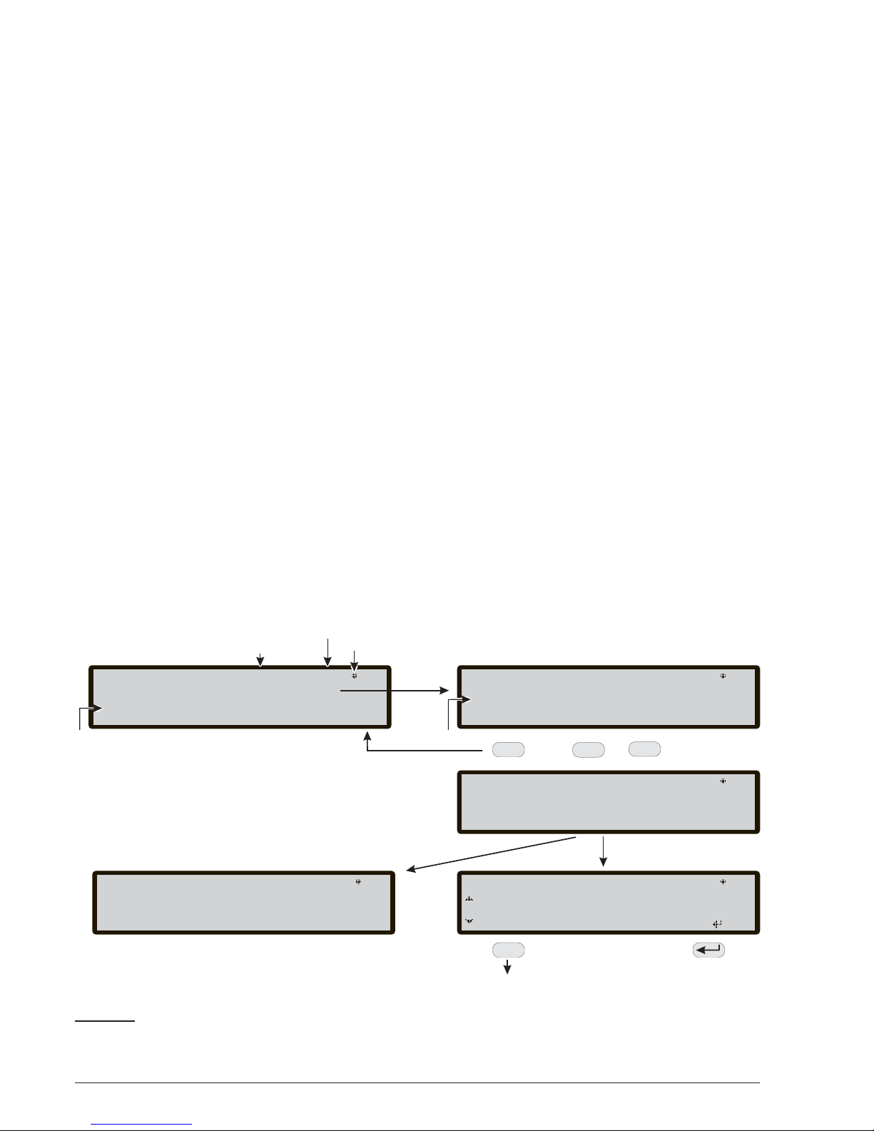
n
Delay to alarm time
Enter the Delay to Alarm time in minutes (max 9).
The amount of Delay to Alarm Time+Investigation Time
should not exceed 10 minutes.
n
Copy on Zone?
Moving on the YES option using the Cursor keys it is
possible to copy the same Delay to Alarm time in all the
zones.
n
MONST. OUTPUT TIME
Enter the period of time that the outputs, with the mono
-
stable option set, stay active once triggered. Value ran
ges from 1 minute to 30 minutes (default value is 3
minutes). It is valid for the entire system.
n
ENABLE SCREEN SAVER
When set as YES, the customizable front page is di
splayed, otherwise it is permanently removed.
n
2 Wire Loops
Each loop may be individually set to work in 2 wires
mode (multiple selection). When the 2 wires option is
selected, it is possible to connect devices on both the
left and right sides of the the loops (2 spurs). This allows
for the connection of up to 6 spurs to the panel, mimi
cing a 6 zones conventional panel.
Notes:
1. In all descriptions of the events, the devices are in
dicated as belonging to a loop. In the case of open
loops, it is not possible to distinguish between the
left and right side. Loop concept, therefore, will not
be meaningful by definition, and localization will be
performed via zones as in the case of conventional
panels.
2. If devices are addressed by the Service Tool, there
are two options to set them in 6 zones which corre
spond to the 6 spurs:
a) Connect addresses from 1-16 to the left side of
loop 1, from 17-32 to the right side of loop 1, and so
on. Then perform the enroll procedure and choose
"By address" option for zone assignment (devices
on the left side of loop 1 will be assigned to zone 1,
those on the right side of loop 1 to zone 2, and so
on.
b) Assign the correct zone to each device, via PC
console or control panel LCD.
3. If devices are not addressed, a mapping procedure
is performed to locate each device and assign the
proper zone to it.
PROGRAMMING FROM THE PANEL 67
Fc501 Panel lev.3 : PROGRAM
access level
If blinking
the panel works
properly
Panel Status
Types of activities
1=Load AUDIO 2=Save AUDIO 3=Load PROG
USB actions
4=Save PROG 5=FW Upgrade 6=Save LOG
0=Extra
Fc501 Panel lev.3 : PROGRAM
Choice of Language
1=load first lang.
2=load second lang.
ESC
1
ABC
2
DEF
o
USB File
OK
Gathering information
RUNNING
USB FC501
Go to select language
to change page
FRANCAIS
PORTUGUESE
wait please
USB FC501
FAILED
CORRUPTED FILE
USB File
TROUBLE
ESPANOL >>> [ ]ESPANOL
ESC
PAGE for
SELECT THE LANGUAGE
Figure 53 The scheme in the figure displays the LCD pages sequence required by this feature: "Language strings
download during panel run time".
Page 68
9 KEY- Restore Default
The Restore Default option from the PROGRAMMING
menu will allow you to restore default setting.
Use the 9 Key to select Restore Default (see Figure
54) .
Alphanumeric keypad No function is related to
Alphanumeric keypad.
Cursor Keys
No function is related to UP, Down,
Right and Left Keys.
ESC Key
The ESC Key cancels the procedure and re
-
turns to the previous page;
ENTER key
The ENTER Key starts the default settings
restore procedure.
+
If the motherboard of the Panel is connected with a
FC500IP module, the procedure to Restore factory
Default (key 9) will have no effect on the FC500IP
module. To restore the FC500IP module to factory
default use the procedure of the FireClass Conso
-
le software.
FC500REP Repeater Address
After the FC501 control panel has been connected, at
the first start-up the FC500REP will verify the presence
of the address and its conformity. If the address is cor
rect, the Repeater will start to work; if the address is not
correct the display will ask to insert a new address. The
display on Figure 55 will be shown.
Alphanumeric keypad Use the alphanumeric keypad
to insert the address of 1 digit.
Cursor Keys
No function is related to UP, Down,
Right and Left Keys;
ESC Key
Use ESC key to cancel the operation and to
step back to previous page.
ENTER Key Use the ENTER Key to confirm the ad
dress.
+
If for any reason the address of a repeater is chan
-
ged by mistake, the system will show the message
in the Figure 55, in this case the address of the re
-
peater can changed using the ESC key.
68 Addressable Fire Panel FC501
All programming data will be lost.
Do you want to continue?
ESC=NO ENTER=YES
WARNING!
Figure 54 Restore default page.
!!FAULT!!
Serial link is down
unable to communicate with the system
press ESC to change repeater address
Figure 55 Display "the repeater link is down".
Page 69

MODIFY
Accessing the Modify Menu
To access the MODIFY menu from the the MAIN page,
you will be asked to enter the Installer 1 (default is
00000) or Installer 2 (default is 99999) password. Each
entered digit will be hidden with the *symbol.
The Installer 1 and Installer 2 can access all the options
described in the User Manual. Read the User Manual
for more information.
Both Installer 1 and Installer 2 can access option 9 - So
-
unders. Only the Installer 1 can access option 7 - Pa
-
ssword.
MODIFY 69
Page 70

70 Addressable Fire Panel FC501
Page 71
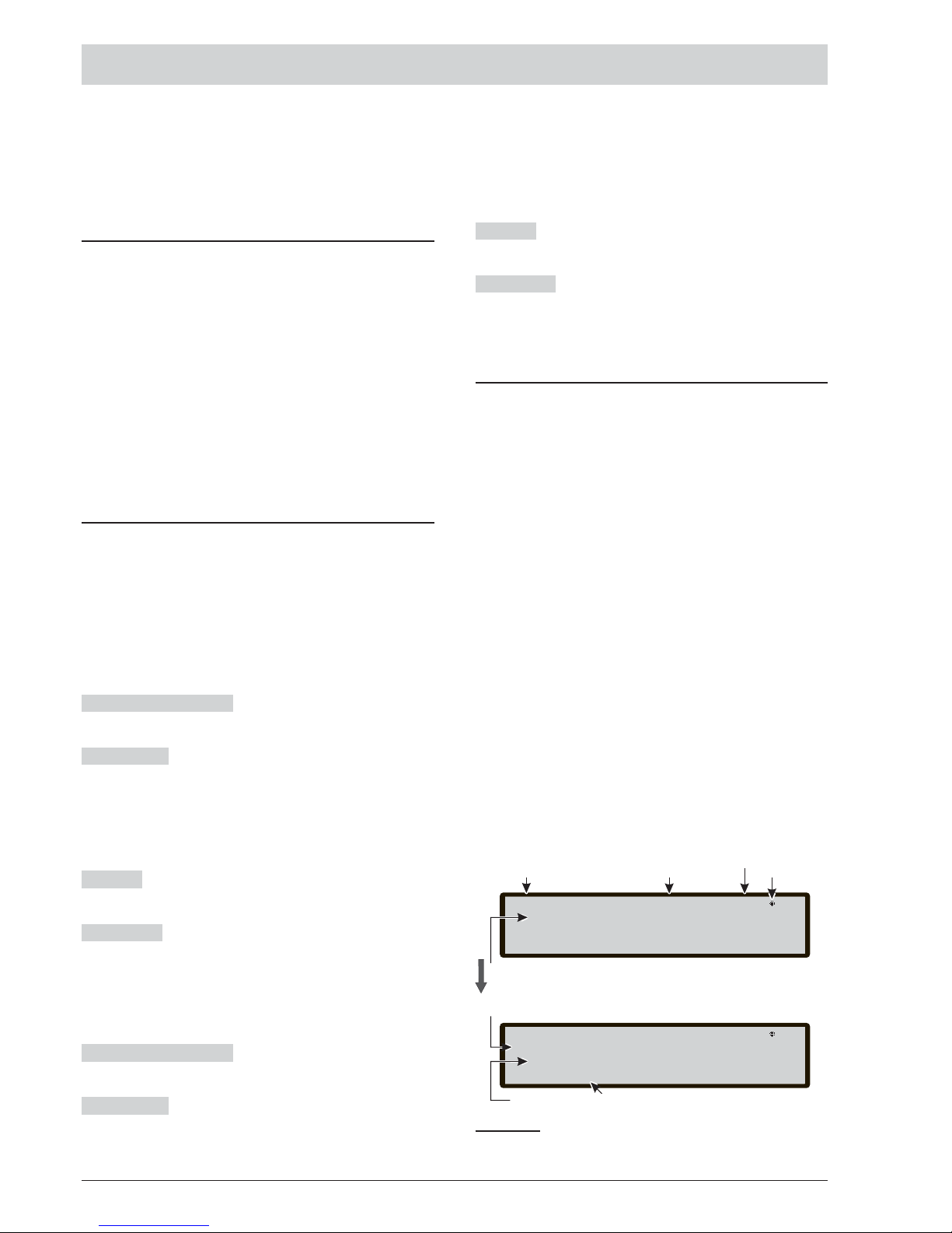
DISABLE
Accessing the Disable Menu
To access the DISABLE menu from the MAIN page,
you will be asked to enter the Installer (default is 00000)
or Installer 2 (default is 99999) password. Each entered
digit will be hidden with the * symbol.
The Installer 1 and Installer 2 can access all the options
described in the User Manual. Read the User Manual
for more information.
Both Installer 1 and Installer 2 can access option 9 - So
-
unders. Only the Installer 1 can access option 7 - Pa
-
ssword.
7 Key - Password (Disable)
This option is enabled only if you enter in the Control
Panel using a Master Installer PIN (Default 00000).
The Key 7 is used to select the Disable Password option, after the option has been selected the corresponding password will be disabled/enabled (Figure 56).
n Select the Password
In this phase:
Alphanumeric keypad Use the Alphanumeric keypad
to select the identification number of Password.
Cursor Keys
Use the UP Key to show the next type of
password;
Use the Down Key to show the previous type of pa
ssword. The types of password are User Password and
Installer Password.
No function is related to the Right and Left Keys.
ESC Key
Use the ESC key to cancel the operation and
to return to previous page.
ENTER Key
Use the ENTER Key to confirm.
n
Disable Password
In this phase, the display shows the current status of the
selected Password (User or Installer). The possible ac
tions are: ENABLE or DISABLE.
Alphanumeric keypad No function is related to
Alphanumeric keypad.
Cursor Keys
No function is related to the UP, Down,
Right and Left Keys.
ESC Key
Use the ESC key to cancel the operation and
to return to previous page.
ENTER Key
Use the ENTER Key to confirm. The User
Interface moves to the MAIN page followed by a panel
reset.
9 Key- Sounders
This option is visible only if you enter the Control Panel
using the Installer 1 (default 00000) or Installer 2 (defa
-
ult 99999) password.
This option allows you to enable or disable all the soun
ders on board or on the loop: SC1, SC2, loop sounder
outputs (SAM, SAB, SNM, AV bases Symphoni soun
ders).
Press 1 to enable all sounders: the event "ALL
SOUNDERS ENABLED" is memorized into the log.
Press 2 to disable all sounders: the event "ALL
SOUNDERS DISABLED" is memorized into the log.
DISABLE 71
FC501 Panel lev.2 : DISABLE
User Pwd
Password Type
FC501 Panel lev.2 : DISABLE
User Pwd
Disabled it?
ENABLED
Present status
Password
Dis./Enable
Request Enabled/Disabled
UP or Down per to select the type
If it blinks the panel
is operating normally
Control Panel name
Access Level
Control panel
Status
Enter the User Pwd number
Figure 56 Display Enabled/Disabled Password.
Page 72
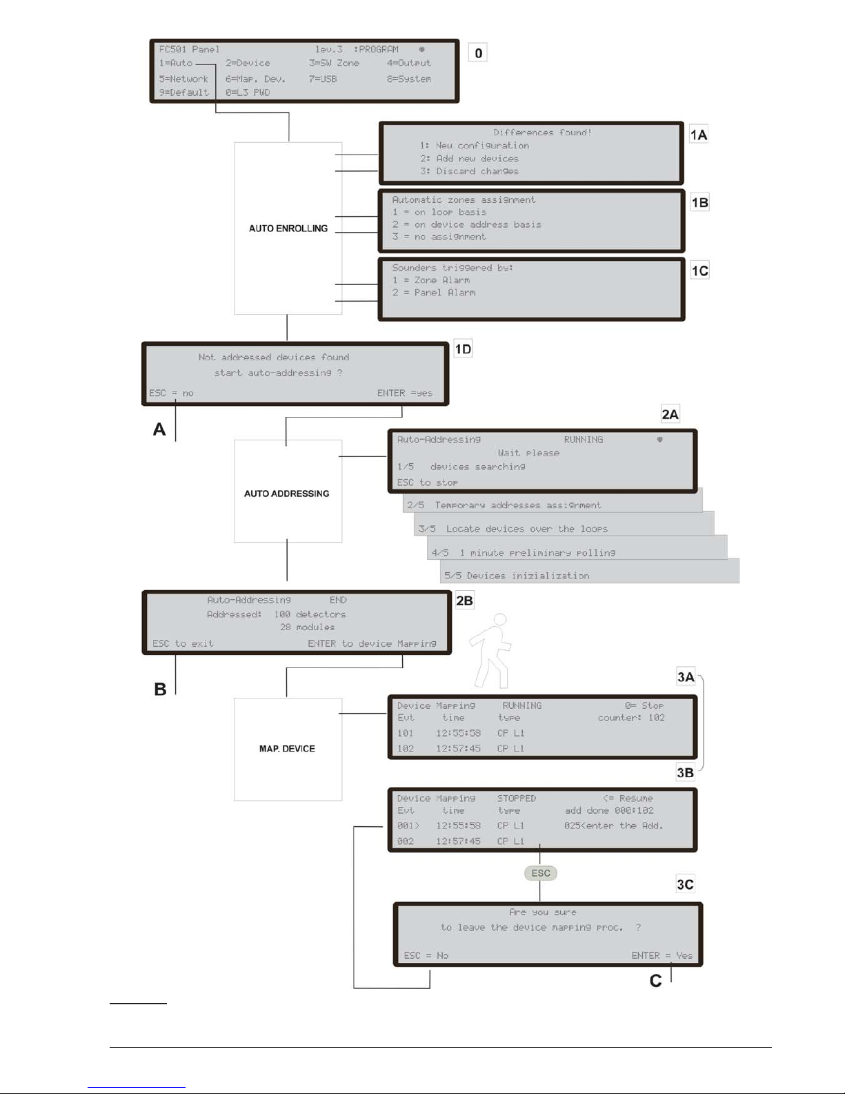
72 Addressable Fire Panel FC501
Figure 55 Programming option "AUTO".
Page 73

QUICK START-UP PROCEDURE
This procedure allows the quick start-up of the FC501
fire detection system.
When the loops are wired, electrically verified and all
the devices have been installed in to the loop, it is pos
-
sible to connect the loops terminals to the panel.
+
Before powering-on the Fire control panel, ensure
that the Earth Line has been connected.
PROCEDURE
1. Turning on the panel will start a FW procedure to
verify/program information for the User Interface
and for the panel, which ensures that functions are
programmed and are consistent. This information
includes:
Ø Selected language
Ø Panel Identification number
Ø The panel Type (FC501-L/FC501-H)
Ø Installed batteries capacity (7Ah/12Ah/38Ah)
2. When the previous data has been verified/programmed, insert the date and time. This step is important as it guarantees the Log file consistency.
At this point the panel will start the first system initializa
-
tion verifying the loops integrity.
+
NOTE: The panel in this phase is configured to ma
nage closed loops (4 wires loop). If it is connected
to a spur (2 wires loop), it will generate broken loop
faults.
At the end of this first initialization phase, the User Inter
-
face will be displayed at the main page with the capabi
-
lity to accept to the command and control functions.
3. Select the function Program pressing the key 1.
4. Insert the installer password (default=00000) every
digit will be masked by * symbol.
5. Choose the option by pressing the key 1.
The panel will start the enrolling procedure.
This procedure is divided into three main phases:
1 Auto-learning
2 Auto- addressing
3 Device Mapping
It is possible to stop the "AUTO" option at the end of
each phase; the results are different.
1 AUTO-LEARNING
In the first phase the panel looks for all the devices on
the loop already addressed (with the service tool).
During this phase, the panel will ask what pattern of au
tomatic assignment of zones shall be applied to found
devices (see Figure 55,1B) and the panel will ask the
sounder's triggering scheme (see Figure 55, 1A).
In the case of panel already configured, it indicates any
differences and asks how to proceed (see Figure 55,
1A), in which case the scheme of Automatic assig
nment of the zones will be applied only to new devices
found.
If you stop the AUTO option at the end of this first phase, Figure 55, A will happen :
Ø The control panel will take over all devices with an
address between 1 and 128.
Ø The programming device at their default configuration.
Ø Automatic assignment of labels.
Ø Automatic assignment of the zones according to the
scheme chosen during that phase.
Ø The output channels of the modules are enabled to
activate on fire alarm of the assigned zone. The so
-
unders, sounders and beacons, sounder bases, AV
(Audio Visual) bases and the FC430SNM modules
will activate according to the trigger scheme chosen
in in this phase. If it was chosen to assign all devices
to system (no zone auto assignment), all of the out
-
put modules, sounders and beacons will be triggered
by the Panel alarm condition.
Ø
The faults "NOT PROGRAMMING DEVICE" and
"wrong addresses" will be generated in the case of
not addressed devices or with address greater than
128, respectively.
+
If the enrolling result differs from the previously sto
-
red loop configuration a warning message will be
displayed and it is possible to reject the present en
-
rolling result, maintaining the previous configura
-
tion, or accept them. See Fig 55 1A.
QUICK START-UP PROCEDURE 73
Page 74

2. AUTO-ADDRESSING
The second phase starts, if during Auto-learning phase,
not addressed devices have been identified or have an
address greater than 128. During this phase all the not
addressed devices will be detected. The panel assigns
them a temporary address and configure them at defa
ult (see Figure 55, 2A).
If you stop the AUTO option at the end of this second
phase, Figure 55, B) will happen:
Ø
The auto assignment of the address to the not ad
-
dressed devices
Ø
The control panel will take over all devices
Ø
The programming devices to their default configura
-
tion.
Ø
Automatic assignment of labels.
Ø
Automatic assignment of zones based on a loop of
belonging.
Ø
The output channels of the modules, sounders and
beacons will be set to active on the alarm of the assi
-
gned zone.
3. DEVICE MAPPING
The third and last phase is activated on demand at the
end of the Auto-addressing phase.
In this phase, it is possible to:
Ø
Locate the positioning in the system of all the devices
through their activation (in the case of output modu
les only, sounders or beacons, they will be suitably
activated by the panel (see Figure 55, 3A).
Ø
Carry out a preliminary test of the system.
Ø
Program the most important parameters of each lo
cated device.
Ø
Automatically assign labels to all devices.
Ø
Assign automatically the zones based on assigned
address to each device.
Ø
Automatically configure the output channels of the
modules, sounders and beacons to activate on the
alarm of the assigned zone.
74 Addressable Fire Panel FC501
LOOP PANEL
MESSAGE
Differences found!
Automatic zones
assignment
Not addressed devices
found
start autoaddressing ?
1
All devices not
addressed
DEFAULT
*
2
Some devices
addressed
+
Some devices not
addressed
DEFAULT
(Applicable only to the
already addressed
devices)
*
*
3
All devices
addressed
DEFAULT
*
4
Fully addressed
Same configuration
CONFIGURED
5
Fully addressed
Different
configuration
CONFIGURED
*
New
configuration
(Applicable only to all
already
addressed devices)
*
Add
devices
(Applicable only to new
already addressed
devices)
*
6
Same configuration
+
Not addressed
devices
CONFIGURED
*
7
Different
configuration (*)
+
Not addressed
devices
CONFIGURED
*
New
configuration
(Applicable only to all
already
addressed devices)
*
*
Add
devices
(Applicable only to the
new
already addressed
devices)
*
*
Table 10 This table shows the type of messages, and relevant action required during the enroll process in function
of the loop and panel configuration. Note (*) indicates that the message is displayed and relevant action is executed.
Page 75

The third phase represents a powerful and flexible tool
that allows to "draw" the plant being in front of the panel
and without the use of a PC and its SW configuration.
A series of controls have been designed to prevent the
generation of incorrect or not manageable conditions.
To locate each device, the address to be assigned:
Ø
does not belong to an older generation device
(FC400 series).
Ø
is in the range from 1 to 128.
Ø
belongs to a new generation device and that device
is present in the list of devices to locate.
Ø
is not among those assigned automatically.
In each case at the end of the device Mapping phase
(see Figure 55,C) a check is performed to detect the
presence of "doubles addresses". In this case the invol
ved addresses are indicated and it is not possible to end
the procedure until the error condition is removed.
+
The procedure for the devices mapping can also be
launched outside the AUTO function,by activating
the programming function called "localization. (Key 6,
on the PROGRAM status) that allows to activate the
procedure for devices mapping on demand, on a
system already configured and without the need to
proceed to their activation. It is meant to correct er
-
rors or change the system "on the run" and use all the
features and capabilities described above.
System default
n
Zone assignment
To mimic a conventional panel, the acquired device
over the loops will be automatically assigned to a prede
-
fined zone. Two different scenarios are possible:
Exit at the end of the Auto Addressing phase without
executing the Device Mapping process, in this case:
Ø
all the devices located on loop #1 will be assigned to
zone #1
Ø
all the devices located on loop #2 will be assigned to
zone #2
Ø
all the devices located on loop #3 will be assigned to
zone #3.
At the end of the Device Mapping process.
The device address to zone assignment scheme is the
follow:
Ø
From address 01 to address 16 assigned to
zone #1
Ø
From address 17 to address 32 assigned to
zone #2
Ø
From address 33 to address 48 assigned to
zone #3
Ø
From address 49 to address 64 assigned to
zone #4
Ø From address 65 to address 80 assigned to
zone #5
Ø From address 81 to address 96 assigned to
zone #6
Ø From address 97 to address 112 assigned to
zone #7
Ø From address 113 to address 128 assigned to
zone #8
If an address is not manually assigned to a device ( either via FC490ST or during the device mapping phase)
no zone will be assigned to it.
The previous zone assignment schemes are applied
also to the first "trigger zone" in the case of output only
devices(sounder, beacon, SNM module,…) or output
channel of Input/output devices.
+
Note that in the case of non zone assigned, the out
-
put channel trigger event is the panel alarm.
n
System default parameters
System default parameters
Temperature detector default values
Label See note (**)
Enablement Enabled
Led blink On
Assigned zone (see: "Zone assignment)
Base type Normal
Use zone setting Yes
Day operating mode A2S
Night operating mode A2S
QUICK START-UP PROCEDURE 75
Page 76

Smoke detector default values
Label See note (**)
Enablement Enabled
Led blink On
Assigned zone (see: "Zone assignment)
Base type Normal
Use zone setting Yes
Day smoke sensitivity Medium
Night smoke sensitivity Medium
Smoke+Temperature detector default values
Label See note (**)
Enablement Enabled
Led blink On
Assigned zone (see: "Zone assignment)
Base type Normal
Use zone setting Yes
Day temp. operating mode A2S
Day smoke operating mode normal
Day smoke sensitivity Medium
Night temp. operating mode A2S
Night smoke operating mode normal
Night smoke sensitivity Medium
CO + Temperature detector default values
Label See note (**)
Enablement Enabled
Led blink On
Assigned zone (see: "Zone assignment)
Base type Normal
Use zone setting Yes
Day temp. operating mode A2S
Day CO operating mode normal
Day CO sensitivity medium
Night temp. operating mode A2S
Night CO mode normal
Night CO sensitivity medium
CO+Smoke+Temperature detector default values
Label See note (**)
Enablement Enabled
Led blink On
Assigned zone (see: "Zone assignment)
Base type Normal
Use zone setting Yes
Day algorithm Universal
Night temp. operating mode Universal
Modules default values
Label See note (**)
Enablement Yes
Led blink On
Activation unit (where applicable) Off
Act as SC1 (where applicable) Off
Input Channels
Enablement Yes
Channel Label See note (**)
Assigned zone Address related
(see: "Zone assignment)
Operating mode Style C, NO
Use zone setting Yes
Output Channels
Enablement Yes
Channel label See note (**)
Trigger zone #1 Address related
(see: "Zone assignment)
Trigger zone #2 None
Trigger zone #3 (where applicable) None
Trigger zone #4 (where applicable) None
Trigger point #1 None
Trigger point #2 None
Trigger point #3 None
Silenceable Yes
Active on disablement (where applicable) Off
Trigger on event Zone Alarm
Delay from alarm Off
Silenceable Yes
Sounder pattern (where applicable) 7Hz fast sweep
Sounder volume (where applicable) high
Beacon enablement (where applicable) Yes
Beacon flash rate (where applicable) 0.5 Hz
DDM module default values
Label See note (**)
Enablement Enabled
Led blink On
External power On
Detector type 4/20 mA Source
Threshold set Set #1
Input Channels
Enablement Enabled
Channel Label See note (**)
Assigned zone Address related
(see: "Zone assignment)
Use zone setting Yes
76 Addressable Fire Panel FC501
Page 77

TSM module default values
Label See note (**)
Enablement Enabled
Led blink On
External power On
Input function Door monitoring
Loop monitoring Off
Door monitoring event Fault
Monitoring time 30s
Input Channel
Enablement Enabled
Channel Label See note (**)
Assigned zone Address related
(see: "Zone assignment)
Operating mode Style C, NO
Output channel
Enablement Yes
Channel label See note (**)
Trigger zone #1 Address related
(see: "Zone assignment)
Trigger zone #2 None
Trigger point #1 None
Trigger point #2 None
Trigger point #3 None
Silenceable Yes
Trigger on event Zone Alarm
Delay from alarm Off
Zones default values
Label Zone AAA(*)
Enablement Enabled
Walk test Off
Detector warning Off
Delay to alarm Off
Drift compensation Off
Double knock Off
Smoke verification Off
Delay to alarm duration 0s
On board programmable outputs default values
Enablement Yes
Channel label tttt y(****)
Trigger zone #1 none
Trigger zone #2 None
Trigger zone #3 None
Trigger zone #4 None
Trigger point #1 None
Trigger point #2 None
Trigger point #3 None
Silenceable Yes
Active on disablement (where applicable) Off
Trigger on event none
Delay from alarm Off
General options default values
Investigation delay 300s
Main fault delay 1m
Delay to alarm 60s
Silence duration 60s
Reset 2s
Loop 1 wires 4 wires
Loop 2 wires 4 wires
Loop 3 wires 4 wires
Day/Night mode Day mode
SC1 disablement Enabled
PSTN communicator enablement Not operative
IP communicator enablement Not present
NETWORK enablement Disabled
Delay from alarm #1 0s
Delay from alarm #2 0s
Delay from alarm #3 0s
Delay from alarm #4 0s
Delay from alarm #5 0s
PSTN communicator default values
Tone check On
Start playing after Selection
Call attempts 3
Iteration 3
Call all telemonitoring numbers No
Call all voice message numbers No
Telephone number label TEL. NUMBER xx(*****)
All Telephone numbers behavior None
Trigger events Panel alarm, Panel Fault
Message #1 to #7 Pre recorded
Notes:
(**) Automatically assigned Module label.
The label is composed by a brief description of the devi
-
ce followed by its address.
Automatically assigned Module channel label
The label is composed by a first part containing the mo
-
dule acronym and address followed by the brief de
scription of the channel using the acronym printed on
the module PCB.
xxx = module acronim
yyy= module address
For example "DDM098: Ingresso A" is the default label for
the input #1 of the FC410DDM module at address 98.
(****) tttt represent the on board output type (4 chars),
SC outpts -> tttt="SC "
Programmabel outputs -> tttt="OC "
y = output number
(*****) xx represent the telephone number ID (2 digits),
QUICK START-UP PROCEDURE 77
Page 78

78 Addressable Fire Panel FC501
Page 79

ACCESSORY
The following is a list of accessories for FC501 control
panel, with a description of the main features. For fur
ther information about these accessories, please refer
to the instructions supplied with the accessories them
selves or download them from the website:
http://www.fireclass.net.
FC500IP - IP Module
The FC500IP is an IP Module which is used to connect
the FC501 fire panel to a LAN.
The IP Module may be connected to a LAN using a pri
vate IP address or a DHCP address.
The same procedures may be performed using the FireC
lass console application, either through the serial port or
the network. With a public IP address, it is also possible to
manage and monitor the control panel from anywhere in
the world, as long as you have access to the Internet.
4B - Universal Base
The 4B Universal base is for use with the
FC460/FC400/600 series of detectors.
The base may be fixed directly to:
Ø British (fixing centres 50mm) or European (fixing
centres 70mm) conduit box.
Ø
4B EM Euro Mounting Box.
Ø
the suspended ceiling, through the CTA adapter.
Ø
directly to the ceiling.
FC460H or FC400H-Addressable Heat Detector
The detector is intended to plug into the following:
Ø
4B 4” Universal Base
Ø
4B-I 4” Isolator Base
Ø
FC430SB Low Power Sounder Base
Ø
FC430LPSB Loop Powered Addressable Sounder
Base.
Ø
FC430LPASB Loop Powered Addressable Soun
-
der/Beacon Base.
Software within the controller is used to interpret the re
turned heat values to raise an alarm or other appropria
te responses according to the type of detector
configured in Fire Class Console.
The mode of detector may be:
Ø
EN54-5 A1R, rate-of-rise normal ambient
Ø
EN54-5 A2S, fixed 60oC
Ø
EN54-5 CR, rate-of-rise high ambient.
FC460P or FC400P - Addressable Optical
Smoke
The FC460P/FC400P optical smoke detector forms
part of the FC460/FC400 Series Addressable Fire de
-
tectors.
Ø
4BI 4”Isolator Base
Ø
4B 4” Universal Base
Ø
FC430SB Low Power Sounder Base
Ø
FC430LPSB Loop Powered Addressable Sounder
Base.
Ø
FC430LPASB Loop Powered Addressable Soun
-
der/Beacon Base.
Software within the controller is used to interpret the re
turned optical and heat values to raise alarm or other
appropriate response according to the type of detector
configured in Fire Class Console.
FC460PH or FC400PH - Addressable
Optical Smoke & Heat Detector
The detector is intended to plug into one of the following:
Ø
4B 4” Universal Base
Ø
4B-I 4” Isolator Base
Ø
FC430SB Low Power Sounder Base
Ø
FC430LPSB Loop Powered Addressable Sounder
Base.
Ø
FC430LPASB Loop Powered Addressable Soun
-
der/Beacon Base.
Ø
Software within the controller is used to interpret the re
-
turned optical and heat values to raise alarm or other ap
-
propriate response according to the type of detector
configured in Fire Class Console. The mode of detector
may be:
Ø
Optical smoke only detector (sensitivity High, Normal
or Low)
Ø
Optical ( sensitivity High, Normal or Low ) and heat
fixed temperature 60
o
C (A2S)
Ø
Heat only rate-of-rise (A1R) detector (no sensitivity
selection)
Ø
Heat fixed temperature 60oC (A2S) (no sensitivity se
-
lection)
Ø
Heat rate-of-rise (A1R) detector and optical smoke
(sensitivity High, Normal or Low)
Ø
HPO (Advanced) smoke detector (sensivity High,
Normal or Low)
Ø
HPO Enhanced with heat fixed temperature 60oC
(A2S)
Ø
HPO Enhanced rate-of-rise (A1R).
ACCESSORY 79
Page 80

FC460PC Addressable Optical Smoke &
Heat Detector & CO
Detector of high performance, of smoke, temperature
and CO. The use of the three elements of the sensor, in
synergy, allows to determine with accuracy the presence
of all types of fires and at the same time having an excep
tional immunity to false alarms.
The functionalities of the FC460PC detector are:
self-monitoring, self-testing, status indicator, remote
LED and threshold compensation. The detector
FC460PC is compatible with the existing bases.
FC410LI - Line Isolator Module
The FC410LI Line Isolator Module is designed to be
used on the FC addressable controller loop circuits. It
monitors the line condition and when detecting a short
circuit will isolate the affected section while allowing the
rest of the addressing circuit to function normally.
The purpose of the FC410LI Line Isolator Module is to en
sure that, on a looped addressable system, no short circu
it fault can disable more detection devices then would be
lost on a conventional non-addressable fire circuit.
FC410MIM - Mini Input Module
Ø The FC410MIM Mini Input module is designed to
monitor fire contacts, such as extinguishing system
control, ventilation control, fire door control etc.The
module provides one identifiable detection spur
which is capable of monitoring multiple normally
open contacts or a single normally closed contact.
The FC410MIM may be mounted in any electrical enclosure with sufficient depth to accommodate
FC410MIM and the contacts monitored by the IN+
and IN- terminals, ie, no field wiring. The remote LED
(if required, not supplied) must be located within the
same electrical enclosure.
FC410MIO - Small Addressable Multi I/0
Module
The FC410MIO Multi I/O Module has three class B inputs
and two outputs from latching relays. The class B inputs
can monitor fire contacts such as extinguishing system
control, ventilation control, fire door control etc. The two
relays outputs are dry form C that provide volt-free relay
changeover contacts. A maximum of two HVR800 High
Voltage Relay Modules can be individually driven and
controlled by an FC410MIO if all HVR800s are powered
by 24V dc or 24V ac. In this application, the HVR800s are
controlled by the two latching relays on the FC410MIO. A
maximum of four HVR800 High Voltage Relay Modules
can be individually driven and controlled by an FC410MIO
if all HVR800s are powered by 120V ac or 240V ac. In this
application, the HVR800s are controlled by the four con
trol outputs (O1+/O1- to O4+/O4-) on the FC410MIO.
FC410SIO - Single Input/Output Module
The FC410SIO Single Input/Output Module is designed
to provide a monitored open collector input and a volt
free relay changeover output.
FC410SIO can switch up to2A@24Vdc.
FC420CP - Addressable Break Glass
Callpoint (indoor)
FC420CP Addressable Break Glass Callpoint is desi
gned to monitor and signal the condition of a switch
contact that is operated by activating the break glass
element. The type of alarm generated by the callpoint is
configured in FireClass Console.The FC420CP call po
int meets the requirements of EN54 Pt.11. The
FC420CP is fitted to a standard surface mount plastic
backbox, standard single gang metal plaster box (35
mm for flush mounting) or standard single gang metal
plaster box (25 mm) with backbox.
FC421CP - Addressable Break Glass
Callpoint (outdoor)
Ø
FC421CP Weatherproof Addressable Break Glass
Callpoint is designed to monitor and signal the condition of a switch contact that is operated by activating
the break glass element. The type of alarm generated by the callpoint is configured in FireClass Console. The FC421CP callpoint meets the
requirements of EN54 Pt.11. The FC421CP is fitted
into a standard weatherproof break glass callpoint
housing.
FC430SAB/SAM - Sounder Base Address
Modules
The Sounder Base Address Modules (FC430SAM
/FC430SAB) are designed to control a loop powered
sounder base for use with the FCsystem, one variant
(FC430SAB) has an integral beacon. They may also be
used to drive a relay base. The units are used to supply
the address decoding in place of a detector, thus provi
ding a loop powered sounder when used in conjunction
with an FC430SB. The modules are colour matched to
the sounder bases. The FC430SAM/FC430SAB is loc
ked into the base using the locking device integral to the
sounder base.
80 Addressable Fire Panel FC501
Page 81

FC430SB - Loop Low Power Sounder Base
The FC430SB Loop Low Power Sounder Base provides
an additional sounder function on the FC addressable
loop circuit. The FC430SB Loop Low Sounder Base re
quires an associated detector in order to operate, as it
uses the address of the detector that is fitted to it. Remo
val of the detector or loss of power to the loop will cause
the sounder to cease operating. A maximum of 30 Soun
der Bases at full volume may be connected to the loop.
4B-I - Isolator Base
The FC460/FC400 Series Detectors, as supplied, use a
common 4B-I Isolator Base assembly.
The base may be fixed directly to:
r
British (fixing centres 50mm) or European (fixing
centres 70mm) conduit box.
r
FC450EMB Euro Mounting Box.
r
Directly to the ceiling.
FC490ST - Loop Service Tool
The FC490ST Loop Service Tool is used to program
the loop address into FC addressable devices. The
FC490ST displays information and performs tests on
devices. It has a 32 character backlit LCD alphanumeric
display, arranged in 2 rows of 16 characters and four
‘softkeys’, F1, F2, F3 and F4. Power for the FC490ST is
derived from 4 AA size nickel metal hydride rechargeable batteries. It may be run from an unregulated +12V
dc input ie, car cigarette lighter connection or 110/230V
ac mains adaptor, both of which will also recharge the
batteries.
FC410BDM - Beam Detector Module
Ø
The FC410BDM Beam Detector Interface Module is
designed to interface FIRERAY 50 Beam Detectors
to the FC Digital Addressable Loop (it must not be
used with other types of beam detector). The
FC410BDM monitors the Fire and Fault contacts and
also monitors for open and short circuits on the con
-
nections between the interface and the beam detec
-
tor. For remote siting of the FIRERAY 50 an optional
BTM800 Terminal Module can be used with 4 core
cable.
The FIRERAY 50 transmitter and receiver units are mo
unted in the same housing.
The FC410BDM Loop Powered Beam Detector Interfa
ce Module is contained on a double sided printed circuit
board (PCB) which is fitted into a custom built fascia
plate with a protective cover being fitted over the PCB,
leaving only the connection terminals exposed. The fa
scia plate is then fitted onto a standard dual-gang back
box with BESA fittings.
FC410CIM - Contact Input Module
Ø
The FC410CIM FC Addressable Contact Input Mod
-
ule is designed to monitor fire contacts such as extin
guishing system control, ventilation control, fire door
control etc. The FC410CIM can be configured as:
r
Two spur circuits (Class B) monitoring multiple nor
mally open contacts, with short circuit giving a fault
output.
r
Two spur circuits (Class B) monitoring single nor
mally closed contacts, with short circuit giving a fault
output.
r
Two spur circuits (Class B) monitoring multiple nor
mally open contacts, with short circuit giving an alarm.
FC410DIM - Detector Input Module
The Addressable FC410DIM provides the ability to con
-
nect and Interface one or two zones of 24V dc 2-wire
conventional detectors (non-addressable) to the Fire
Alarm Controller.
The FC410DIM monitors the status of detectors and wi
-
ring to detectors and signals detector and wiring status
back to the Controller.
FC410RIM - Relay Interface Module
The FC410RIM Relay Interface Module provides one
volt-free relay changeover contact on a latching relay.
The relay is controlled by a command sent from the FC
fire controller via the addressable loop. The relay state
(activated, deactivated or stuck) is returned to the controller.
FC400CH - Addressable Carbon Monoxide
+ Heat Detector
Ø
The FC400CH carbon monoxide plus heat detector
forms part of the FC400 Series Addressable Fire detec
tors.
The detector is intended to plug into the following:
Ø
5B 5” Universal Base.
Ø
FC450IB 5” Isolator Base.
Ø
FC430SB Low Power Sounder Base.
Ø
FC430LPSB Loop Powered Addressable Sounder
Base.
Ø
FC430LPASB Loop Powered Addressable
Sounder/Beacon Base.
The detector is designed to transmit, to a remote Fire
Class controller, digital signals which represent status
of the carbon monoxide and heat elements of the detec
tor. Software within the controller is used to interpret the
returned carbon monoxide and heat values to raise
alarm or other appropriate response according to the
type of detector configured in Fire Class Console.
ACCESSORY 81
Page 82

801RIL - Remote LED Indicator
The 801RIL Remote Indicator is used where a detector
LED is not visible ie, when the detector is mounted in a
roof void, lift shaft etc.The 801RIL is mounted to a single
gang electrical box and is supplied with 2 x M3.5 screws.
801HL - Remote LED Indicator
The 801HL Remote Indicator is used where a detector
LED is not visible ie, when the detector is mounted in a
roof void, lift shaft etc.
The 801HL provides a larger indicator for use in place of
the 801RIL when longer distances are involved or in
VdS influenced markets.
The 801HL can be mounted to any suitable flat surface
and has fixing centres at 60 and 80mm.
HVR800-High Voltage Relay
Ø
The HVR800 High Voltage Relay Interface is a
non-addressable multi-voltage relay module (operat
ing from 24V dc, 24V ac, 120V ac and 240V ac).
The encapsulated HVR800 provides a 10 amp
volt-free contact that can be used to extend the con
tact ratings of FC410RIM Addressable Relay Module
applications.
A maximum of four HVR800s can be individually
driven and controlled by an FC410MIO Small Addressable Multi-Input/Output module if all HVR800s
are powered by 120V ac or 240V ac. For ac operation, no external dc power supply unit is required to
operate the relay.
When used to switch 24V dc, the HVR800 must be
provided with an external 24V dc supply which
should be switched through the clean relay contacts
of an FC410MIO or FC410RIM.
DPK4/DPKI
Ø
The DPK4/DPK4I duct probe units have been devel
oped to detect smoke in ventilation ducts. These duct
probe units can used in combination with a wide
range of detectors and are suitable for addressable
and conventional systems. The duct probes can op
erate across a wide range of air velocities from 1m/s
to 20m/s. The Duct Probe units have a built-in
FireClass Universal Base 5B.There is a range of alu
minium probe tubes available for air ducts up to 1500
mm.
FIRERAY 50/100-Optical Beam Smoke
Detector
The Detector comprises of a Transmitter and Receiver
contained within one enclosure.
The Transmitter emits an infrared light beam that is re
flected via a prism mounted directly opposite and with a
clear line of sight. The reflected infrared light is detected
by the Receiver and analysed.
The Detector has a maximum lateral detection defined
by the local National Standard. As a guide a common
lateral distance of 7.5m will be used in this guide. Use
the latest beam detector standards EN54 part 12,
VdS2095 or BS5839 part 1 for further guidance.
The optimal beam distance from the ceiling will be bet
ween 500mm and 600mm, again the Local National
Standard will give guidance.
Range: Fireray 100 = 50-100 meter
Fireray 50 = 5-50 meter
Coverage area: Fireray100 = up to 1500 sqm.
Fireray 50 = up to 750 sqm.
FIRERAY 3000
The FIRERAY 3000 Optical Beam Smoke Detector is
ideal for applications where the line of sight for the IR
(infra-red) detection path is narrow and where the building structure uses reflective surfaces.The unit emits a
narrow beam of infra-red (IR) light in order to monitor for
smoke and is controlled using a compact low level controller. It allows for the installation of 2 detectors for
each system controller.There is a 2-wire interface between controller and receiver. For each detector there
are separate fire and fault relays.The FIRERAY 3000
has been designed so that it can be installed by one
operator with its laser assisted alignment methods combined with easy to use alignment LED's offering visual
feedback. Integrated laser alignment aid can be activa
ted at the controller or at the receiver head.
Ø
Range:5-120 metres, configurable per set of Detec
-
tors
FIRERAY 5000
The FireRay 5000 motorised, auto-aligning infrared op
tical beam smoke detector can be installed with up to 4
detector heads per system. Once the detector heads
are connected, using the Easifit First Fix system, an in
tegral LASER, which is aligned along the optical path of
the beam, can be activated. This allows the reflective
prism to be sighted quickly. Once the LASER has been
used to coarsely align the beam, the Auto-Optimise
beam aligment system takes over and automatically
steers the beam into the optimum position. The System
Controller retains one set of Fire and Fault relays that is
common to all detectors installed.
Ø
Range: Each detector is configurable from 8m to
100m.
82 Addressable Fire Panel FC501
Page 83

FC410LPSY and FC410LPAV loop
powered sounders and sounder-beacons
Ø
The FC410LP Series of Loop Powered Addressable
Sounder/ Sounder-Beacons are designed to be
driven from an FireClass control panel via the ad
-
dressable loop. The FC410LP Series of sound
-
ers/sounder beacons consist:
FC410LPSYR:Sounder (indoor use) - red housing
FC410LPSYW:Sounder (indoor use) - white housing
FC410LPSY:Sounder IP65 (outdoor use) - red
housing
FC410LPAVR:Sounder-Beacon (indoor use) - red
housing
FC410LPAVW:Sounder-Beacon (indoor use) white housing
FC410LPAV:Sounder-Beacon IP65 (outdoor use) red housing
The sounder has two volume settings ‘High’ (103 dB
±3) or ‘Low’ (90 dB ±3).
The beacon has two flash rates ‘Slow Flash’ (1/2 Hz)
or ‘Fast Flash’ (1 Hz).
The FC410LP devices are synchronised, but not
synchronous with other FireClass sounders
(FC410SNM) and beacons (FC430SAB).
The first flash of the beacon is synchronised with the
start of the tone.
The FC410LP devices have a built in two port isolator.
FC410LPBS-R/W loop powered sounders
and sounder-beacons (EN54-23)
The FC410LPBS Series of Loop Powered Addressable
Sounder/ Sounder-Beacons are designed to be driven
from a FC501 control panel via the addressable loop.
The FC410LPBS Series of sounders/sounder beacons
consist:
FC410LPBS-R: Sounder (indoor use) - red housing
FC410LPBS-W: Sounder (indoor use) - white housing
FC410LPAV: Sounder-Beacon IP65 (outdoor use) - red
housing
The sounder has two volume settings ‘High’ (103 dB ±3)
or ‘Low’ (90 dB ±3).
The beacon has two flash rates ‘Slow Flash’ (1/2 Hz) or
‘Fast Flash’ (1 Hz).
The FC410LPBS devices are synchronised, but not
synchronous with other FireClass sounders and beacons
of the FC400 series.
The first flash of the beacon is synchronised with the start
of the tone.
The FC410LPBS devices have a built in two port isolator.
The table in Table 11 demonstrates the connection bet
ween the managed devices in the current version and the
the new EN54-23
FC430LPSB and FC430LPASB Loop
Powered Addressable Sounder/Beacon
Base
Ø
The FC430LP Series of Loop Powered Addressable
Sounder/Sounder- Beacons are designed to be driven
from an FC501 control panel via the addressable loop.
Tone, volume and flash rates are set in FireClass Con
-
sole.
The sounder has four volume settings ‘High’ (90dB ±3),
‘Mid High’ (80 ±3dB), ‘Mid Low’ (70 ±3dB)or ‘Low’ (60dB
±3). The beacon has two flash rates ‘Slow Flash’
(1/2Hz) or ‘Fast Flash’ (1Hz).The FC430LP Series
have a built-in line isolator.
FC430LPBSB Loop Powered Addressable
Sounder/Beacon Base (EN54-23)
Ø The FC430LPBS Series of Loop Powered Addressable
Sounder/Sounder- Beacons are designed to be driven
from an FC501 control panel via the addressable loop.
Tone, volume and flash rates are set in FireClass Console.
The sounder has four volume settings ‘High’ (90dB ±3),
‘Mid High’ (80 ±3dB), ‘Mid Low’ (70 ±3dB)or ‘Low’ (60dB
±3). The beacon has two flash rates ‘Slow Flash’
(1/2Hz) or ‘Fast Flash’ (1Hz).
The FC430LPBS Series have a built-in line isolator.
ACCESSORY 83
FireClass Product
code (Current Dev.)
FireClass Device
name (Current Dev.)
Description
FireClass
Product code
(EN54-23 Dev.)
FireClass
Device name
(EN54-23 Dev.)
516.800.758 FC430LPASB
Loop Powered Beacon
Sounder Base
516.800.973 FC430LPBSB
516.800.763 FC410LPAVR
Loop Powered
Beacon/Sounder (indoor use)
red
516.800.970 FC410LPBS-R
516.800.764 FC410LPAVW
Loop Powered
Beacon/Sounder (indoor use)
white
516.800.971 FC410LPBS-W
516.800.766 FC410LPAV
Loop Powered
Beacon/Sounder IP65
(outdoor use)
516.800.972 FC410LPBS
Table 11 Connection between the current version and the new EN 54-23.
Page 84

+
It is possible to substitute old devices with corre
spondent new ones (EN54-23), keeping the same
program data. When the old device is physically re
moved from the loop, the control panel will signal
the "No answer" fault. When the new device with
the same address is connected to the loop, the
control panel will restore the "No answer" fault and
automatically update its internal database with the
new device type.
It is not possible to substitute new devices
(EN54-23) with old ones (they are not EN54-23 ap
proved).
FC410SNM Sounder Notification Module
Ø
The FC410SNM Sounder Notification Module is de
-
signed to provide an output, in response to a com
-
mand signalled from a controller, to activate a
number of polarised and suppressed sounders. The
sounders are powered from an independent power
supply and the module is capable of passing up to a
maximum of 2A (eg, 24V dc 50mA company sound
-
ers or a mixture of different current rated sounders
not exceeding a maximum current of 2A).
+
The possibility of the configuration of extinction, al
though present in the FC410SNM module, is not
available for FC501 control panel.
FC410TSM – door control module
The FC410TSM Door Control Module is designed to
close a fire door in case of alarm or fault. The door is
normally kept open by electromagnets. The door control module disconnects the electromagnets from power
supply in order to allow the door to close. The
FC410TSM has a relay changeover output and a moni
-
tored input. The FC410TSM contains an integrated line
isolator and self-monitoring circuits (monitoring of com
-
munication with a panel, loop power monitoring), which
enables the fire door to be closed when communication
with a panel is lost for longer than 45s (±5s) or the loop
power drops below Umin=19V for more than 15s (± 5s).
In addition, the FC410TSM monitors the external 24V
supply.
FC410DDM – Universal fire and gas
detector module
The FC410DDM provides the ability to connect and in
-
terface 2 zones of 20 V DC 2-wire conventional fire de
-
tectors, or two 4-20 mA signalling sensors, to the
FireClass fire alarm controller. The FC410DDM moni
-
tors the status of the detectors and the wiring to the de
-
tectors and signals detector and wiring status back to
the controller. The conventional detector circuits can be
configured to monitor 1 or 2 Class B spur circuits The
4-20 mA signalling sensors may be one of two types:
Ø
Current sinking
Ø
Current sourcing.
FC410QIO Quad input output module
The module provides four monitored digital inputs and
four potential free relay changeover outputs.
The outputs are monitored with parallel contacts of the
relays. The outputs can be connected to an Auxiliary Vol
-
tage source and its voltage can be monitored. Additio
nally, all the outputs can be connected to the HVR800,
for switching high power galvanic isolated loads. For
more details refer to the HVR800 documentation.The
module has an integral loop isolator. If this activates, a
yellow LED illuminates. The activation remains in place
until the short is removed. The digital input monitoring
and isolator functions are both configurable.
Maximum relay current: 2A.
Maximum relay voltage: 30V.
FC410QRM Quad relay module
The module provides four voltage free relay changeo
ver outputs. The outputs are monitored, with parallel
contacts of the relays. The outputs can be connected to
an Auxiliary Voltage source and its voltage can be mo
nitored. Additionally, all the outputs are configurable to
the HVR (High Voltage Relay) mode, which allows you
to connect up to four HVR800 modules for switching; for
example 240V loads galvanically isolated.
The module has an integral loop isolator. If this activates a yellow LED illuminates. The activation remains in
place until the short is removed.
Maximum relay current: 2A.
Maximum relay voltage: 30V.
FC410QMO Quad Monitored Output
Module
The module comprises of four relays with selectable wi
ring supervision.
The output wiring is monitored for any short or open cir
cuit. Spur and Loop configurations are supported.
The module has an integral loop isolator. If this activa
tes, a yellow LED illuminates. The activation remains in
place until the short is removed.
84 Addressable Fire Panel FC501
Page 85
SPECIFICATIONS
These specifications are for installers with knowledge
of the control panels and fire control panels in general.
Technical features
Some of the technical features, regarding the terminals
on the Main, are described in the following table.
The following table shows the technical features of the
Repeater FC500REP:
REPEATER FC500REP
Operating voltage 27.6Vdc
Maximum current 80mA
Temperature range -5 to +40°
Storage Temperature -40 to +80 °C
Operating Humidity
Up to 95%
non-condensing
Dimensions (W*H*D) 390x215x50 mm
Weight 2.05 Kg
Description of the terminals
The terminals of the Main board and Switching power
supply, are described briefly in the Table 13: the
standby (normal) status is the first, followed by the
alarm status. Moreover, the Voltage present during the
different operating conditions is indicated for each terminal, as well as the maximum current (in amps) that
can circulate.
+
Notes (1) and (2) are valid for the table 10.
Notes (3) and (4) are valid for the table:
" MAX WITHDRAWABLE CURRENT"
1) For the power supply of the external devices. (see
table 11).
2) Connect a 3900 ohm resistor between the [+] and [-]
terminals of the SC1, SC2 Outputs, if not used (see ta
-
ble 11).
3) The sum of the currents of SC1 and SC2 must not
exceed 500 mA.
4) The sum of the currents of 24A and 24R must not ex
-
ceed 500 mA.
SPECIFICATIONS 85
Control Panel FC501-L
FC501-H
FC501-HK
Main voltage
110/230 V~ 110/230 V~
60/50 Hz -15/+10%
Aux. Outputs
Nominal Voltage
27.6V
Aux. Outputs Min.
and Max. Voltage
19.0 ÷ 27.6V
Minimum output
voltage
19.0Vdc ±5%
Max current drawn
1.1A (110V)
0.65A (230V)
1.6A (110V)
0.8A (230V)
Ripple 1%
Maximum internal
resistance of the
battery and
associated circuitry
1
W
Temperature range -5 to +40°C
Storage
Temperature
-40 to +80°C
Operating Humidity Up to 95% non-condensing
Dimensions
(W*H*D)
335*369*115 mm
Weight 3Kg(without batteries)
Table 12 FC501 Technical features.
Page 86

86 Addressable Fire Panel FC501
TERM. DESCRIPTION v(V) i(A)
MAIN BOARDS
+L1-
LEFT
(+)Loop 1-Positive signal, left side.
(-)Loop 1-Negative signal (return), left side
——
+L1-
RIGHT
(+)Loop 1-Positive signal, right side.
(-)Loop 1-Negative signal (return), right side
——
+L2-
LEFT
(+)Loop 2-Positive signal, left side.
(-)Loop 2-Negative signal (return), left side.
——
+L2-
RIGHT
(+)Loop 2-Positive signal, right side.
(-)Loop 2-Negative signal (return), right side.
——
+L3-
LEFT
(+)Loop 3-Positive signal, left side.
(-)Loop 3-Negative signal (return), left side.
+L3-
RIGHT
(+)Loop 3-Positive signal, right side.
(-)Loop 3-Negative signal (return), right side.
SH Terminal for connection of the shield of cables
+RS485- SERIAL BUS. Terminals to connect the FC500REP and FC500MFI modules — —
[M]
[24R]
24 V RESET ABLE AUXILIARY POWER SUPPLY:
negative present on terminal [M];
positive present on terminal [24R].
27.600.5(1)
—
[M]
[24A]
24 V AUXILIARY POWER SUPPLY:
negative present on terminal [M];
positive present on terminal [24A].
27.600.5(1)
—
[LE]
[LI]
[-]
Terminal for connection of the external telephone line
Terminal for connection of the internal telephone line
Terminal for connection of the Earth cable
[NC]
[NO]
[C]
FIRE
FIRE ALARM OUTPUT - Non-Supervised:
standby è [C] connected to [NC] with [NO] open
;
in the event of ALARM è [C] connected to [NO] with [NC] open — —
[NC]
[NO]
[C]
FAULT
FAULT ALARM OUTPUT - Non-Supervised:
standby è [C] connected to [NC] with [NO] open
in the event of fault è [C] connected to [NO] with [NC] open — —
+BAT- BATTERY CONTROL PANEL POWER SUPPLY 27.6
[OC1]...
[OC2]
Programmable Outputs(Open collector)- Silenceable-Bypassable
(Disabled)-Supervised
(The polarity is not programmable)
27.6
[MIK]
[SPK]
[BLK]
[RED]
FUTURE USE
[SC1]
[SC2]
(Programmable, SC2 only),Supervised, Silenceable, Bypassable (Disabled) ALARM Outputs:
Panel in Standby è negative on [+] terminal; positive 27.6V on [–] terminal
Panel in Alarm è positive 27.6V on [+] terminal; negative 0 V on [–] terminal —
(2)
Table 13 Terminals description.
Page 87

Table of distribution of currents
SPECIFICATIONS 87
FC501-H/FC501-HK CONTROL PANEL
SWITCHING POWER SUPPLY BAW75T24 (Imax=2700mA)
12 Ah BATTERY
I
load 80% in 24h
= (12x0.8)/24=400mA -> 400mA
I
for panel
= 2700-400=2300mA
Panel load distribution
I
electronic
=175mA
I
total
LOOPs @40V
(*)
= 400mA à 625mA @Vbattery
I
total
OUTPUTS
(*)
= 1350mA
I
FC500IP
= 100mA
(**)
I
residual
= 50mA
38Ah BATTERY
I
load 80% in 24h
= (38x0.8)/24=1267mA -> 1300mA
I
for panel
= 2700-1300=1400mA
Panel load distribution
I
electronic
=175mA
I
total
LOOPs @40V
(*)
= 200mA à 313mA @Vbattery
I
total
OUTPUTS
(*)
= 650mA
I
FC500IP
= 100mA
(**)
I
residual
= 163mA
NOTE: (*)I
total
LOOPs is the sum of the currents absorbed on the three loops;
I
total
OUTPUTS is the sum of the currents drawn by the terminals SC1, SC2, 24A, 24R, 24V-RS485.
If the FC500IP module will not be used, the relative amount of current (100mA) can be taken from the SC1,SC2,24A,
24R, 24V-RS485 terminals.
+
The notes and the table "Max withdrawable current" apply to the two models of control Panels.
MAX WITHDRAWABLE CURRENT
TERMINALS max Current
SC1 500mA
SC2 500mA
24A 500mA
24R 500mA
24V-RS485 500mA
FC501-L CONTROL PANEL
SWITCHING POWER SUPPLY BAW50T24 (Imax=1800mA)
7 Ah BATTERY
I
Load 80% in 24h
= (7x0.8)/24=233mA -> 250mA
I
for panel
= 1800-250=1550mA
Panel load distribution
I
electronic
=175mA
I
total
LOOPs @40V
(*)
= 200mA à 313mA @Vbattery
I
total
OUTPUTS
(*)
= 850mA
I
FC500IP
= 100mA
(**)
I
residual
= 113mA
12Ah BATTERY
I
load 80% in 24h
= (12x0.8)/24=400mA -> 400mA
I
for panel
= 1800-400=1400mA
Panel load distribution
I
electronic
=175mA
I
total
LOOPs @40V
(*)
= 200mA à 313mA @Vbattery
I
total
OUTPUTS
(*)
= 750mA
I
FC500IP
= 100mA
(**)
I
residual
= 63mA
Page 88

© FireClass
Tyco Fire & Security GmbH
Victor von Bruns-Strasse 21
8212 Neuhausen am Rheinfall
Switzerland
Tel.: +41 (0)52 633 02 44
Fax: +41 (0)52 633 02 59
www.fireclass.net ISTISFKEFC501 7.0 120916 V10
 Loading...