

Page 1
120.515.224_FC-D-421CPI-F, doc. version 4.0, 9. November 2018
© 2018 Johnson Controls. All rights reserved. All specifications and
other information shown were current as of document revision date and
are subject to change without notice.
www.fireclass.net
Tyco Fire & Security GmbH, Victor von Bruns-Strasse 21, 8212
Neuhausen am Rheinfall, Switzerland
FC421CP-I FIRECLASS Fire detection system
Call Point Removal
How to remove the FC421CP-I
1 Remove the four fixing screws used to lock
the callpoint to the backbox.
2
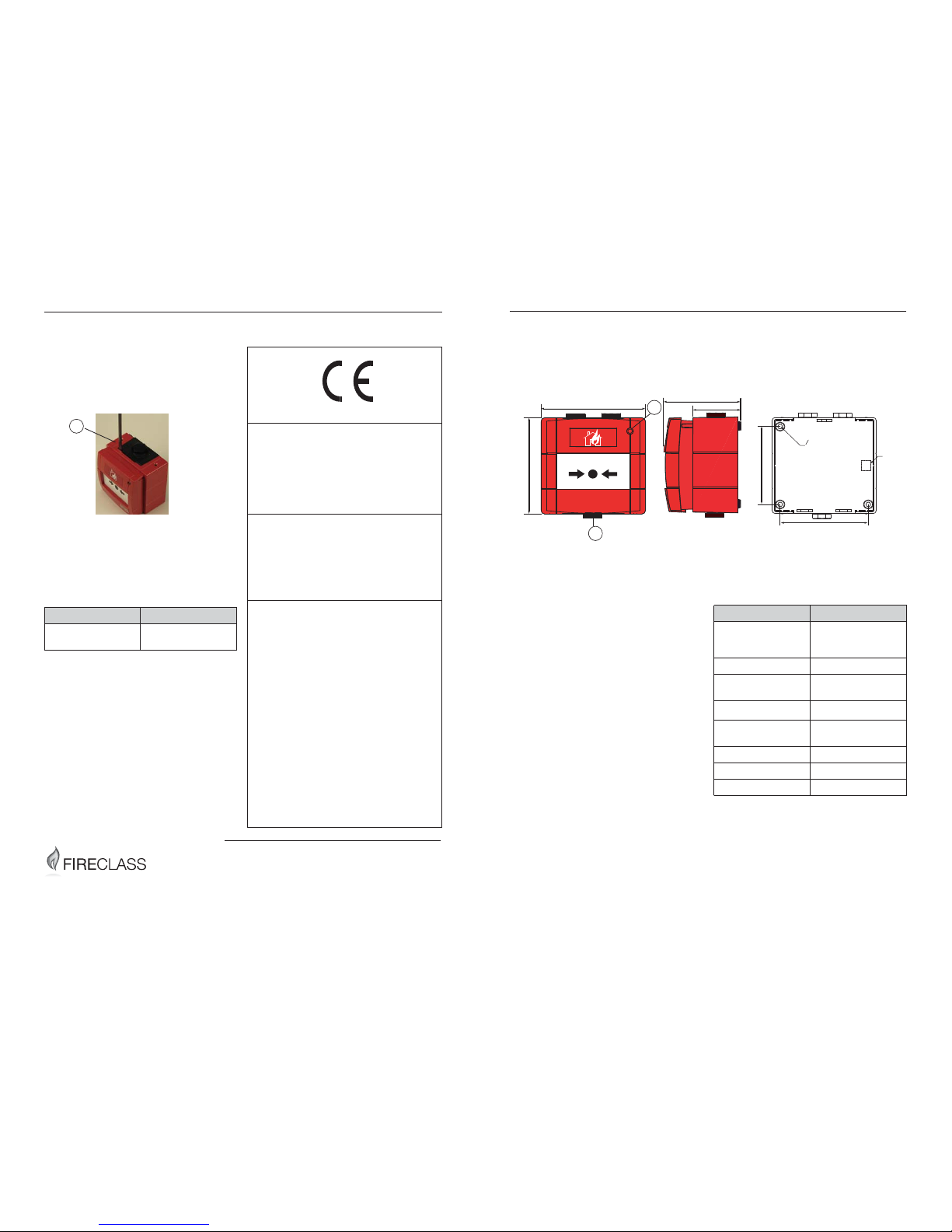
Place the edge of a large flat bladed screwdriver into the slot between the callpoint
cover and the backbox (see item 1 in Fig 3).
3 Gently twist until the latches are disengaged.
4 Pull the cover away from the backbox.
Ordering Information
CPR Information
Fig. 3: FC421CP-I Removal
1 – Screwdriver inserted into slot
Component Ordering Numbers
FC421CP-I Outdoor
CP with isolator
514.800.806
Table 3: Ordering Information
1
0832
Tyco Fire & Security GmbH,
Victor von Bruns-Strasse 21,
8212 Neuhausen am Rheinfall,
Switzerland
15
DoP-2015-4170
EN 54-11 and EN 54-17
Manual callpoint with Short-Circuit Isolator
for fire detection & fire alarm systems for
buildings
Type A, Indoor
FC421CP-I
Essential Characteristics
EN54-11
Nominal activation conditions / Sensitivity
and Performance under fire conditions: Pass
EN54-17
Performance under fire conditions: Pass
EN54-11 and EN54-17
Operational reliability: Pass
Durability of operational reliability temperature resistance: Pass
Durability of operational reliability; vibration
resistance: Pass
Durability of operational reliability; humidity
resistance: Pass
Durability of operational reliability; corrosion
resistance: Pass
Durability of operational reliability; electrical
stability: Pass
FIRECLASS Fire detection system FC421CP-I
Fixing instructions Doc. version 4.0 1/4
FC421CP-I Outdoor Weatherproof Resettable
Callpoint
Introduction
The FC421CP-I Weatherproof Addressable
Resettable Callpoint is an outdoor manual callpoint.
The callpoint is designed to monitor and signal
the condition of a switch contact that is operated
by activating the resettable element.
The FC421CP-I is fitted onto a standard KAC
weatherproof backbox, which is supplied with
the callpoint.
The
FC421CP-I has an integral short-circuit isola-
tor for monitoring the field wiring.
The FC421CP-I callpoint meets the requirements
of EN54 Pt. 11 and EN54 Pt. 17.
Technical Specification
Table 1 shows the technical specification information.
Fig. 1: FC421CP-I Outdoor Weatherproof Resettable Callpoint - Overall and Fixing Dimensions
1 – Short Circuit Isolator Activation (Yellow) and Alarm Indicator LED (Red)
2 – Test/Release Key Access
3 – Earth Continuity Terminal (Internal)
97.5
93
73
45.5
76.53
83.8
04.5 FIXING HOLES
(3) PLACES
1
2
Parameter Value
System Compatibility Use only with FIRE-
CLASS Fire Alarm
Controllers
Environment Outdoor applications
Operating
Temperature
-25 to +70
o
C
Storage Temperature
-30 to +70
o
C
Operating Humidity Up to 95 %
non-condensing
Dimensions (HWD) 93 x 97.5 x 73 mm
Weight 240 g
IP Rating IP67
Table 1: Technical Specifications
Page 2
2/4 Fixing instructions Doc. version 4.0
FC421CP-I FIRECLASS Fire detection system
Terminals
Table 2 shows the terminal information.
Address Programming
The FC421CP-I has a default factory set address
of 255.
The FC421CP-I is programmed with the address
prior to installation using an address programming tool. The associated ancillary programming
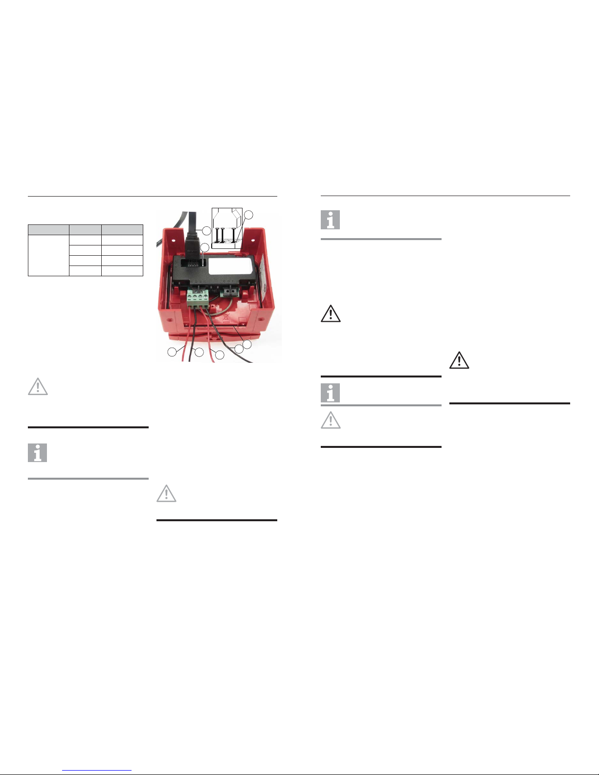
lead plugs into the programming port (see
items 1 and 2 in Fig 2). Refer to Fig 2 for proper
orientation.
Mounting & Cabling
How to mount the FC421CP-I with
earthing plate fitted
1 Mount the backbox to a suitably flat surface in
the required location, using the three fixing
holes and screws provided in the installation
kit.
2 Fit the appropriate cable glands into the
20 mm diameter threaded holes as required.
Description Marking Comment
MX Loop
Interface
1 Loop+ IN
2 Loop- Left
3 Loop+ OUT
4 Loop- Right
Table 2: Terminals
NOTICE
Ensure that the pins of the ancillary
programming lead are inserted
completely into the lower row of the
programming port (see item 7 in Fig 2)
for effective communication with the
Address programming tool.
Site Drawings
Once the address has been programmed, take note of the device location and address number, to include on
site drawings.
Fig. 2: FC421CP-I Rear View and Wiring Information
1 – Ancillary Programming Port
2 – Ancillary Programming Lead
3 – Connected to Loop+IN
4 – Connected to Loop-Left
5 – Connected to Loop+Out
6 – Connected to Loop-Right
7 – Programming Lead Orientation
8 – Gasket
NOTICE
Ensure that the cable entry holes are in
the vertical plane. The backbox can be
mounted with either the single or the
double entry holes at the top.
6
3
5
4
2
1
7
8
FIRECLASS Fire detection system FC421CP-I
Fixing instructions Doc. version 4.0 3/4
The 2 hole stoppers with plastic washers are
provided for use where cable glands are not
required.
3 Connection to the FC421CP-I is made via the
4 way terminal connector as shown in Fig. 2,
ensuring correct polarity.
Each terminal can accommodate a conductor
of up to 2.5 mm
2
.
.
4 Place the callpoint squarely over the backbox
and carefully push the callpoint until the locating clips have engaged.
Use the four fixing screws to lock the callpoint into place.
5 Select all cables in accordance with local
standards,
6 Couplers are to be used with MICC cable.
Earthing
An Earth Continuity Terminal is situated in the
rear of the backbox. This is designed to accommodate 2 conductors of up to 2.5 mm
2
.
An earthing plate is provided for continuity of
metal conduits. This must be placed behind the
backbox prior to fixing the box to the wall.
If the earthing plate is fitted, fit the 3 spare washers (supplied with each call point) between the
metal earth continuity strap and the call point
backbox.
Wiring Notes
There are no user-required settings (such as
switches or headers) on the FC421CP-I.
All wiring must comply with local installation
regulations and local fire system design
requirements.
All conductors to be free of earths. For typical
wiring configuration see Fig 2.
Spare Washers
Use only the supplied spare washer(s)
to fit the respective cable gland(s) or
hole stopper(s).
CAUTION
Ensure that the backbox’s cable entry
holes are not expanded to
accommodate cable glands wider than
20 mm in diameter. It must not be
subjected to stress by the cable or
conduit.
Ensure that all the cable entries and
unused entry points are securely sealed
against water and moisture ingress.
Sealant
It is recommended to use Loctite 5331
as sealant.
NOTICE
Ensure that the gasket is correctly
seated in the channel on the rear of the
cover. The gasket should be replaced if
damaged.
WARNING
While installing the FC421CP-I:
Do not overtighten the fixing
screws
Avoid using lubricants, clean-
ing solvents or petroleum
based products.
 Loading...