

Page 1

INSTALLATION TO FC470CV ANCILLARY COVER
1) Assemble the FC410SIO to FC470CV ancillary cover, using
the four screw and washers provided.
2) Fit cover onto dual-gang backbox.
ADDRESS SETTINGS
The FC410SIO has a default factory set address of 255, this must
be set to the loop address of the device using the FC490ST Loop
Service Tool. The FC410SIO may be programmed with the ad
dress prior to being installed by using the internal programming
port (see Fig. 2) or after being installed by using the programming
port on the front cover (see Fig. 3).
+
Note: once the address has been programmed, take note of
the device location and address number, to include on site
drawings.
+
Note: this device use one address only on the loop.
CABLING
Cables are to be selected in accordance with the system design
document and the requirements of the applicable standards.The
maximum section of the cable that can be connected at any one
terminal is 2.5mm
2
. The section is calculated based on the charac-
teristics of the cable and the load.
ORDERING INFORMATION
FC410SIO: Single Input / Output Module
FC470CV: Ancillary Cover
RECYCLING INFORMATION
Customers arerecommended to dispose of their used equipments
(panels, detectors, sirens, and other devices) in an environmentally sound manner. Potential methods include reuse of parts or
whole products and recycling of products, components, and/or
materials.
WASTE ELECTRICAL AND ELECTRONIC EQUIPMENT
(WEEE) DIRECTIVE
In the European Union, this label indicates that this
product should NOT be disposed of with household
waste. It should be deposited at an appropriate facility
to enable recovery and recycling.
The manufacturerreserves the righttochange the technical speci
fications of this product without prior notice.
TECHNICAL SPECIFICATION
TypeIdentificationValue: 148
System Compatibility: Use only with FC Fire AlarmControllers
Environment: Indoor Application only
Operating Temperature: -25 to +70
o
C
Storage Temperature: -40 to +80
o
C
Operating Humidity: Up to 95% non-condensing
Dimensions (HxWxD): 85x60x15mm
Mounting Requirements: Dual-gang electrical box
Recommended Wire Size: Min. 1.5 mm
2
Max. 2.5 mm
2
Battery Requirements
Standby current:
Alarm current:
0.3 mA
3.0 mA
Addressable Device
Conditions: – Normal
– Active
– Short Circuit wiring fault
– Open Circuit wiring fault
– Device Type Invalid
– Device No Response
Input Circuit
EOL
Alarm resistor
3K3
680 W
Electromagnetic Compatibility
The FC410SIO complies with the following:
Ø product family standard EN50130-4 in respect of Conducted
Disturbances, Radiated Immunity, Electrostatic Discharge,
Fast Transients and Slow High Energy;
Ø EN61000-6-3 for emissions.
INTRODUCTION
The FC410SIO Single Input/Output Module is designed to provide
a monitored open collector input and a volt free relay changeover
output.
FEATURES
Ø
FC410SIO can switch up to2A@24Vdc
WIRING & INSTALLATION NOTES
The following notes apply:
1) There are no user-required settings (such as switches or head
-
ers) on the FC410SIO.
2) All wiring must conform to the applicable standards.
3) All conductors to be free of earths.
4) Verify the correct polarity of wiring before connecting the
FC410SIO to the addressable loop circuit.
5) For FC410SIO typical wiring configuration see Fig. 4.
ENGLISH
Page 2
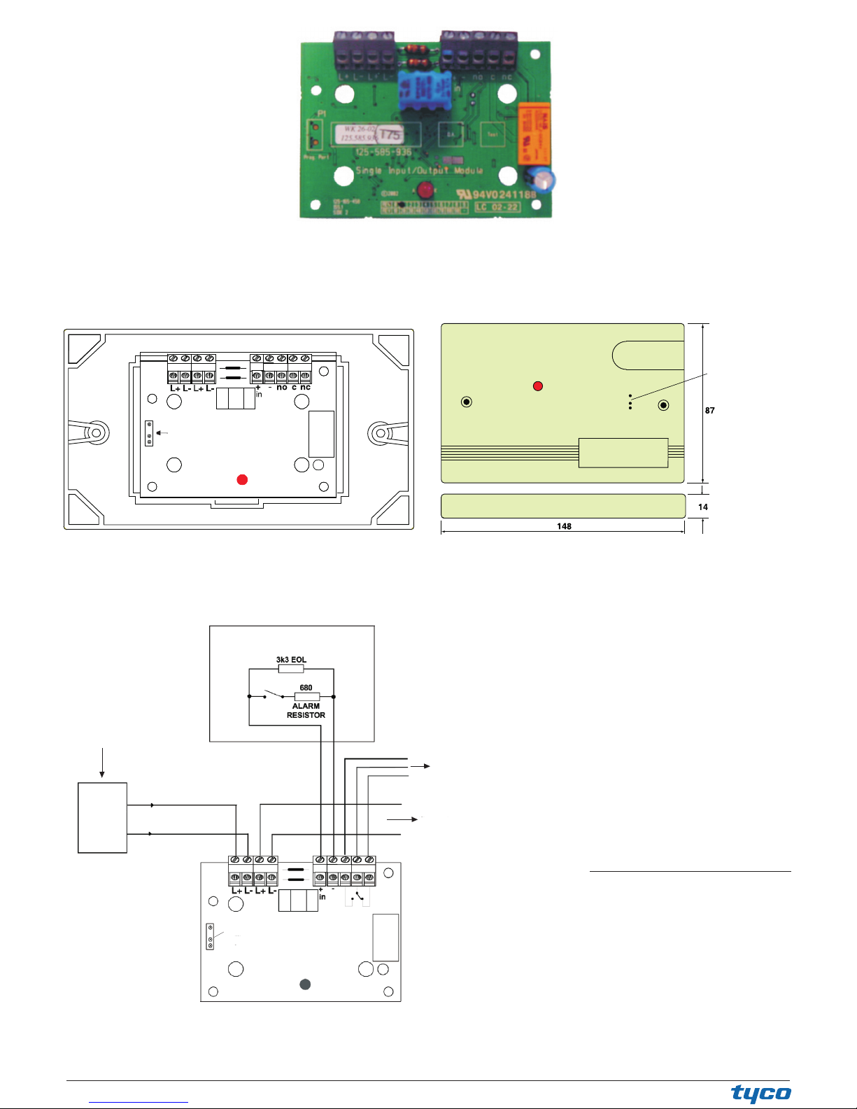
PORTA DI PROGRAMMAZIONE
PROGRAMMING PORT
PROGRAMMIERANSCHLUSS
CONTATTO MONITORATO
MONITORED CONTACT
ÜBERWACHTE EINGANGSLINIE
AL CARICO COMMUTATO
TO SWITCHED LOAD
ZU SCHALTENDE LAST
ALLA CENTRALE DI CONTROLLO O
DISPOSITIVO SEGUENTE
TO CONTROL EQUIPMENT OR
NEXT DEVICE
ZUM NÄCHSTEN ELEMENT
DALLA CENTRALE DI CONTROLLO O
DISPOSITIVO PRECEDENTE
FROM CONTROL EQUIPMENT OR
PREVIOUS DEVICE
FC
+L1
-L1
LEFT
Schema di collegamento semplificato del FC410SIO
FC410SIO simplified wiring diagram
FIG. 4
Typische Verdrahtung des Ein- / Ausgangselementes FC410SIO
PORTA DI PROGRAMMAZIONE
PROGRAMMING PORT
PROGRAMMIERANSCHLUSS
FIG. 2 FC410SIO fissato al coperchio
FC410SIO fitted to cover
FC410SIO ins Gehäuse eingebaut
PORTA DI PROGRAMMAZIONE
ADDRESS SETTING PORT
PROGRAMMIERANSCHLUSS
FIG. 3 Placca per FC410SIO
FC410SIO Facia Plate
FC410SIO Ein- / Ausgangselement Vorderseite
Modulo 1 Ingresso / 1 Uscita FC410SIO
FC410SIO Single Input / Output Module
FIG. 1
FC410SIO Ein/Ausgangselement
© FireClass
Via Gabbiano 22,Z. Ind.S. Scolastica
64013 Corropoli (TE), Italy
Hillcrest Business Park Cinderbank
Dudley West Midlands
DY2 9AP United Kingdom
www.fireclass.co.uk
[email protected]
 Loading...