

Page 1
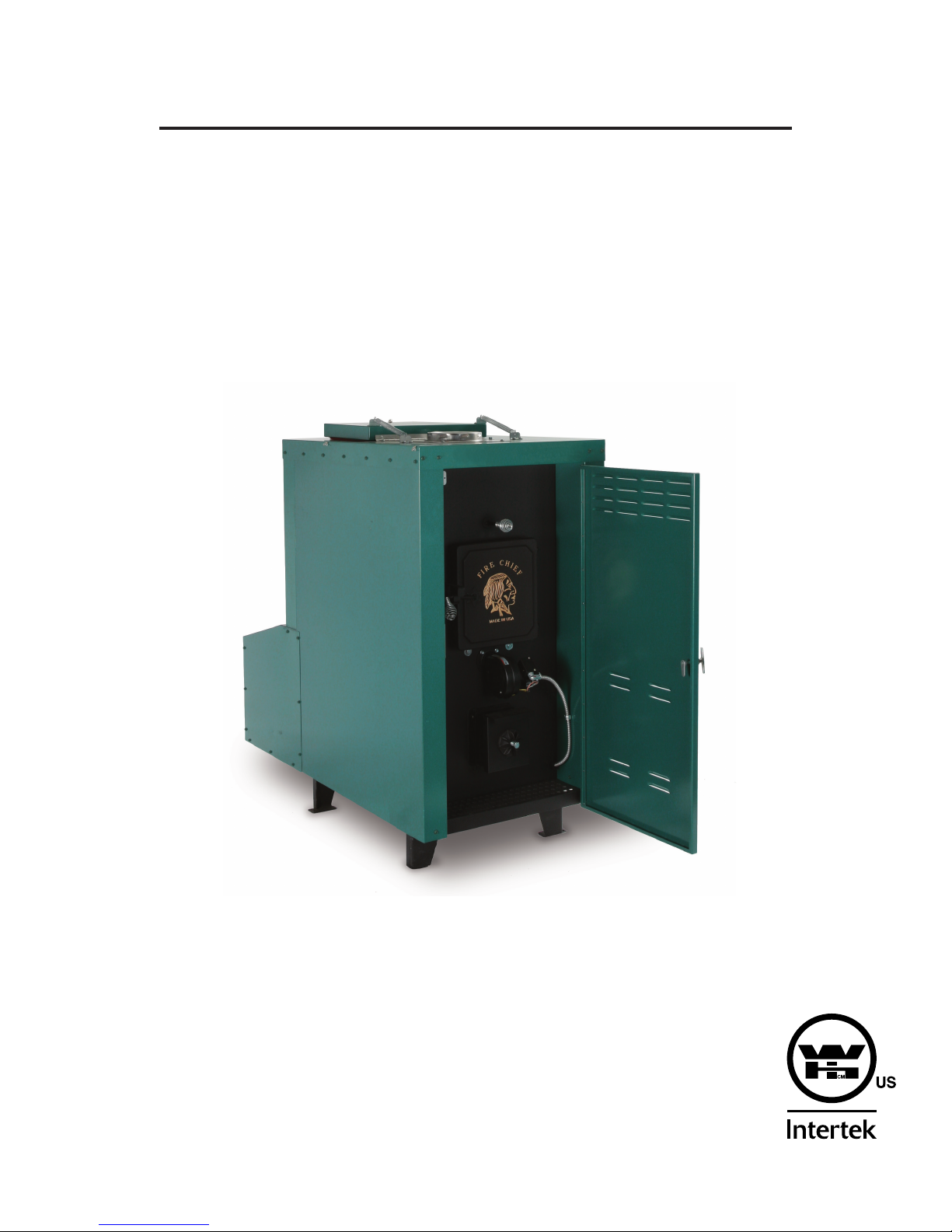
FIRE CHIEF FURNACE
WOOD AND COAL BURNING
OUTDOOR FURNACE
MODEL: FCOS1800D, FCOS2200D
REVISION VII
OCTOBER 2013
Manufactured by:
Fire Chief Industries
10950 Linpage Place
Saint Louis, MO 63132
1-800-875-4788
MADE IN USA
Tested to the
UL391 Standard
Page 2
FIRE CHIEF OUTDOOR FURNACE MANUAL
MODEL: FCOS1800D, FCOS2200D
SAVE THESE INSTRUCTIONS
Congratulations! You have selected the nest quality outdoor wood and coal burning furnace, manufactured with pride in the
USA. Please take a few moments to carefully read the owner’s manual. By taking the time to familiarize yourself with your
new Fire Chief Furnace, you will be able to look forward to years of trouble-free, dependable service.
Installation:
• First, check local codes. The installation must comply with all local rulings and requirements.
• This furnace is an outdoor hot air furnace and must not be altered in any way.
• This furnace requires a back-up electric generator, 2000 watts minimum, in case of power failure.
• Always have a properly installed and functioning smoke detector installed in your home.
• To prevent accidental injury, do not allow anyone who is unfamiliar with the furnace to operate it.
• Spend time familiarizing yourself with your Fire Chief Furnace, especially the different settings and the effects they
have on burn patterns. It is impossible to predict how each setting will affect your furnace, due to variations in
conditions, fuels, and temperatures.
• When making plans to install your outdoor furnace, the rst thing you need to think about is the placement of the
unit. Although you can install the Fire Chief Furnace up to 30 feet from the home, a much shorter distance is
recommended to provide better airow. The furnace has been tested for clearance of 31 inches from the home;
this would give maximum airow and provide the highest efciency.
Transportation Damage
Every effort has been made to ensure that your Fire Chief Furnace will arrive in perfect condition. Any visible damage should
be noted on the freight bill at the time of delivery. If upon unpacking your furnace, you nd damage has occurred during
transit, notify your dealer immediately. Your dealer will advise you what actions must be taken to correct the problem.
Disclaimer Notice
The listed BTU rating of your new Fire Chief Furnace was obtained using laboratory calculations. The actual BTU output you
experience may vary somewhat depending on the type, condition, and moisture content of the fuel used, damper adjustment,
chimney type and other variables. Therefore, the manufacturer disclaims any guarantee as to the BTU output or capacity
of your furnace. Fire Chief Furnace disclaims any responsibility for the following: installation of a furnace that has been
altered or modied in any way; installation of the furnace other than as instructed in this manual; installation and or use of any
component or part not approved by Fire Chief Furnace for use on this furnace. Be sure to complete and return your warranty
card within 30 days of purchase in order to activate warranty coverage on your furnace.
Manufacturer’s Notice
Please be advised that periodic changes are made to improve the furnaces. Therefore the information in this manual may not
be completely applicable to your Fire Chief Furnace. Please refer to markings on the appliance for additional information.
THIS IS AN OUTDOOR WOOD AND COAL BURNING FURNACE ONLY AND
SHOULD NOT BE ALTERED IN ANY WAY.
1
Page 3
TABLE OF CONTENTS
General Information 3
Furnace Clearances and Operation 4
Bypass Damper 5
Installing the Anchor Plate 6
Chimney Location and Clearances 6
Wood Storage and Care 7
Furnace Installation 7
Installing Electrical Components 8
Grounding Furnace 9
Hot Air Duct and Cold Air Return Installation 10
Burying Ductwork 10
Types of Installations 11
Central Duct Connections 11
Mobile Home Down Draft Furnace Connection 12
No Ductwork Connection 12
General Operation 13
First Wood Fire 13
Loading Wood 13
First Coal Fire 14
Fuel Recommendations 14
Disposal of Ashes 15
Heat Dump and Fuse Link System 15
Draft Blower and Spin Draft 16
Creosote Formation 16
Creosote Prevention 16
Power Failure 16
Maintaining Your Furnace 17
Furnace Diagram with Parts List 19
Grate System Diagram 21
Blower Motor Assembly Diagram 21
Wiring Diagram 22
Troubleshooting 23
Warranty Information 28
DOUBLE CHECK TO MAKE SURE YOU HAVE RECEIVED ALL OF THE
REQUIRED COMPONENTS. IF YOU FIND THAT THERE IS A PART MISSING,
CALL 1-800-875-4788 FOR FASTEST SERVICE. PLEASE DO NOT GO BACK TO
THE DEALER. THE DEALER DOES NOT HAVE REPLACEMENT PARTS.
2
Page 4

General Information
ALWAYS KEEP YOUR WOOD COVERED YEAR ROUND; DRY WOOD WILL PRODUCE MORE BTU OUTPUT AND LONGER BURN
TIMES.
The Fire Chief Furnace is an airtight central solid fuel outdoor furnace engineered to accommodate the heating requirements of the
average sized home, even during winter’s coldest months. It is constructed of high grade, heavy gauge steel and is continuously welded
to assure the utmost in structural strength. The insulated rebox will accommodate a log up to 28 inches in length (1800 model) and 34”
(2200 model). In addition, the heat exchanger is lined with rebrick to ensure many years of energy efcient service.
The design of the secondary combustion chamber increases fuel efciency by creating a “secondary burn” of smoke and wood gases
before they are vented up the chimney. By sending the gases back through the secondary combustion chamber, less fuel is wasted, the
furnace burns at a higher efciency, and for longer burn times.
The cast iron door is custom tted to provide an airtight seal, greatly extending the burn time and ensuring maximum efciency in fuel
consumption. The heavy-duty cast iron grates aid in convenient ash removal and reduce maintenance; the insulated wrap-around sides
are designed for maximum heat transfer.
For total comfort and convenience, a thermostatically controlled 1800 CFM circulation blower system has been installed. The blower
draws the cold air from the home, across the heat chamber before going through the hot air duct and returning the warm air to your home.
This fully automatic blower furnishes rapid heat disbursement to your home, minimizing recovery time. Average burn time per load of
fuel is 6 to 12 hours depending on wood or coal type and condition, desired temperature within the home and amount of fuel. We have
incorporated all of these features as standard equipment, offering you the most efcient, durable and affordable appliance possible.
Abnormally cold weather could reduce the burn time.
Your Fire Chief Furnace is designed to be either a supplemental or central heating source for your home. This wood and coal burning
furnace may be installed in parallel with a properly operating electric, gas or oil-red central furnace, listed or certied in accordance with
a nationally recognized safety standard, and within clearances specied on Fire Chief Furnace nameplate. When in a parallel installation
the static pressure of the central furnace plenum may not exceed 0.15 water column inches and the maximum setting on central furnace
limit switch is 182°F. With the Fire Chief Furnace in an “Interconnection Arrangement” your furnace should be upstream of the central
furnace. The Fire Chief Furnace warm air supply should never be connected to return air for the central furnace. A qualied installer
should perform the installation.
This is a wood and coal burning furnace – it cannot be turned “off and on” to control the furnace temperature like gas or electric furnaces.
Once the re is established, it has to burn until it burns itself out.
INCLUDED WITH YOUR FIRE CHIEF FURNACE:
2 – 10” starter collars
1 – 12” starter collar for cold air return
1 – owner’s manual with warranty card
1 – electrical control kit (shipped on top of furnace)
1 – tube of high-temp silicone caulk
1 – 25’-10” exible insulated duct
ELECTRICAL CONTROL KIT PARTS:
6 – 1/4”- 20 bolts
2 – 1/4” nuts
23 – #10 green screws with rubber gasket for blower housing cover
4 - #10 x 3/4” screws for fan limit control box
1 – draft blower
1 – cover for fan limit control
1 – fan limit control with wire conduit
1 – blower motor and housing
1 – electrical control box
1 – wall thermostat (you must purchase 2-wire thermostat wire separately)
1 – blower housing cover
1 – blower housing bottom
4 – U nuts for blower housing
2 – #10-32 machine screws
2 – #10-32 nuts
4 – #10 x 3/4”screws for chimney anchor plate
1 – anchor plate
1 – spare fuse link
3 – 1/4” x 20 x 3/4” bolts
3
Page 5
Furnace Clearances and Operation
Before beginning your installation, consult with local authorities regarding the codes governing all such installations. DO NOT connect
your Fire Chief Furnace to any ue that is servicing ANY other appliances.
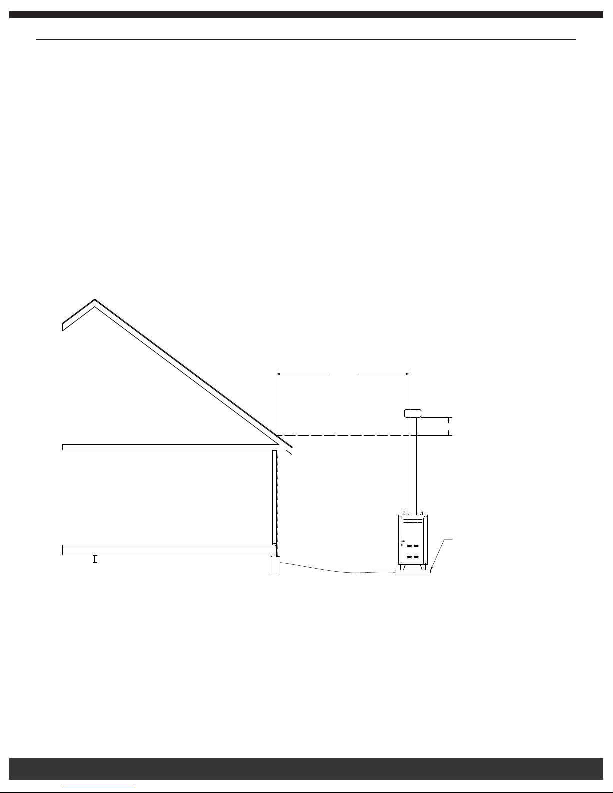
The Fire Chief Furnace may be placed outdoors or indoors. If outdoors, it must be placed on a level, non-combustible base, preferably
a 4’ x 8’ concrete pad, as close to the home as clearances to combustibles permit – do not place the furnace more than 30 feet from
the house. The furnace must be connected to a grounded electrical circuit with access to a backup generator (2000 watt minimum). If
locating the furnace more than 10’ from the home, a minimum of 6’ of Class “A” HT 2100 All Fuel 6 inch Chimney Pipe is required. If
installing indoors, your furnace must be placed on a non-combustible oor. Air for combustion must be provided into the room where the
furnace is located. Allow air free access to furnace for combustion and ventilation.
Maintain the following clearances:
• Front = 48 inches
• Rear = 31 inches
• Sides = 12 inches for wood and coal burning applications
• Heat Duct = 6 inches for the rst 16 inches from the back of the furnace, and 3 inches beyond
Maintain the “10/2 Rule” for the ue, which says the ue must be 2 feet higher than any part of the building or peak of the roof within a
horizontal distance of 10 feet. The 2 foot height does not include the cap. See diagram below.
10 FEET
10 Feet
2 FEET MINIMUM
2 Foot Minimum
4’ x 8’
4' X 8'
Level Concrete Pad
LEVEL CONCRETE PAD
Class “A” HT 2100 All Fuel 6 inch Chimney Pipe is required for optimum performance and must maintain a 2 inch clearance from
combustibles. The Fire Chief Furnace will ship with an anchor plate and four #10 ¾” galvanized screws with washers and gaskets to
match the chimney your dealer supplies. If the anchor plate provided with your furnace does not t the chimney your dealer has in stock,
please call our toll free number, 1-800-875-4788 for assistance.
IMPORTANT: Please keep in mind that different chimney manufacturers’ pipe will not interchange with other brands. A tube of hightemp silicone caulk is included with your furnace. Before using the silicone to install the anchor plate to the top of your Fire Chief
Furnace, ensure the chimney you purchased will t the anchor plate.
Guy wire brackets are attached to the sides of the Fire Chief Furnace. A heavy gauge of stainless steel wire can be purchased from your
dealer or at a local hardware store to use as guy wire to help support your chimney. Attach the appropriate chimney pipe lengths to the
adaptor plate nishing with a chimney cap. IMPORTANT: Your furnace requires its own chimney system and cannot share a ue with any
other product. DO NOT USE GALVANIZED OR BLACK PIPE TO VENT YOUR FURNACE.
4
Page 6
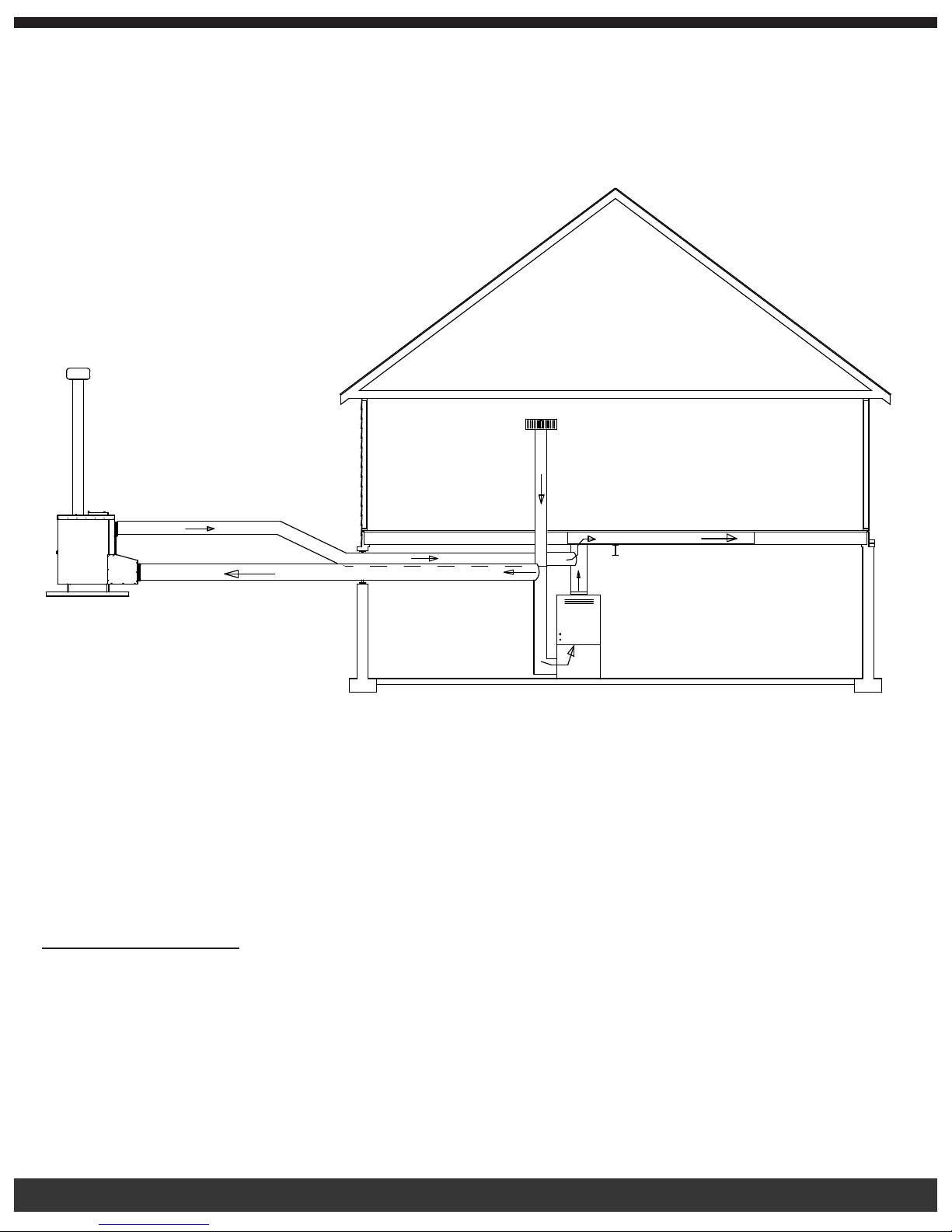
Once you have met local requirements governing the installation and positioning of the furnace, install the Electrical Control Kit. Open the
Electrical Control Kit and conrm that all items were shipped with your Fire Chief Furnace. IMPORTANT: ENSURE THE POWER CORD
IS PLUGGED INTO A GROUNDED ELECTRICAL SUPPLY. Do NOT connect the furnace to your ductwork at this time. Build a small re
– DO NOT ll the rebox to full capacity during the initial ring. Your new furnace has a protective coating of oil or paint on the surface,
which could produce smoke or odors during the initial ring and will burn off. Allow adequate ventilation during this initial, break-in ring
to let any odors escape. This initial ring also allows the metals to cure. After successfully completing the initial ring, you are ready to
attach the hot air duct and cold air return to complete your installation. See diagram below.
You must install the wall thermostat for the furnace to operate. When the wall thermostat calls for heat, the draft motor will engage,
allowing combustion air to ow into the rebox. This causes a hotter re, increasing the heat in the heat chamber. When the home
reaches the selected temperature on the wall thermostat, it will disengage the draft motor and the re in the rebox will reduce to a low
burn until the thermostat calls for another heat cycle. The fan limit control is factory pre-set at 160° as the “ON” temperature setting and
100° as the “OFF” temperature setting. This means when the heat chamber reaches 160°, the blower will turn on; when the chamber
cools, the blower will turn off. This process is called a heating cycle.
IMPORTANT: FOR TECHNICAL SUPPORT OR CUSTOMER SERVICE
ISSUES, DO NOT RETURN TO THE DEALER (THE DEALER DOES NOT HAVE
REPLACEMENT PARTS), CALL FIRE CHIEF AT 1-800-875-4788.
BYPASS DAMPER:
The bypass damper has several purposes: starting the re, improving the efciency, and cleaning the chimney. When starting a re in the
Fire Chief Furnace, you must pull the rod out for a stronger draft during ignition. Once the re has started, close the bypass, which allows
the secondary combustion chamber to engage, increasing the furnace’s operation to peak efciency. If the bypass rod is not closed
during operation, the furnace’s efciency will be greatly reduced, allowing the heat to escape up the chimney. Finally, when cleaning the
chimney, the rod must be pulled out to allow any build-up in the chimney to fall into the rebox.
THIS UNIT IS NOT TO BE CONNECTED TO A CHIMNEY FLUE THAT SERVES ANOTHER APPLIANCE.
5
Page 7
INSTALLING THE ANCHOR PLATE:
Note: Check with your dealer for the anchor plate that connects to Class A HT2100 chimney. IMPORTANT: BEFORE YOU FOLLOW
THE NEXT STEPS, ENSURE THE ANCHOR PLATE YOU RECEIVE MATCHES YOUR CHIMNEY PIPE, AS CHIMNEY PIPE IS NOT
GENERIC AND WILL NOT INTERCHANGE.
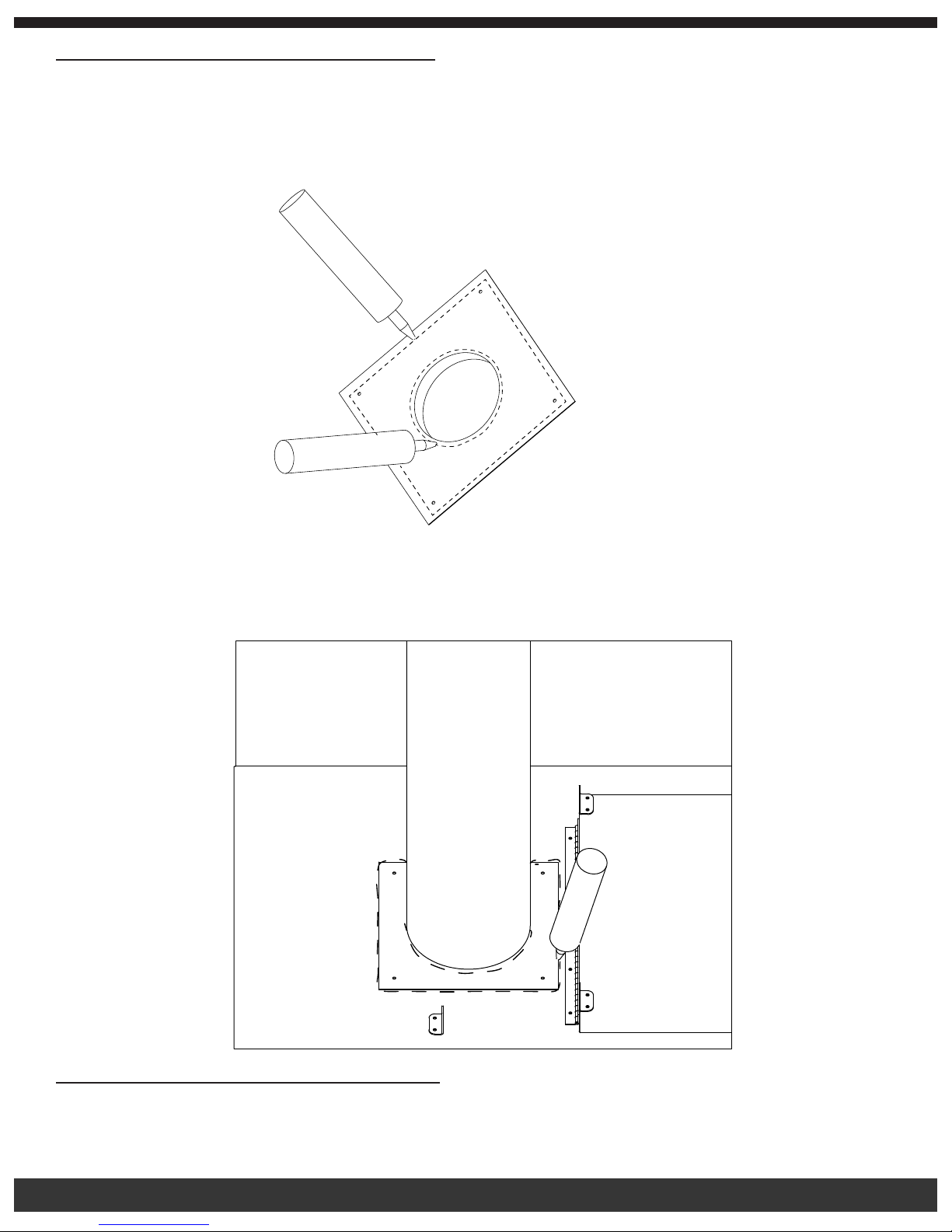
1. Using the diagram below as a guide, caulk the bottom of the anchor plate around the center pipe shaft.
PLACE A LINE OF
SILICONE CAULK ON CHIMNEY ADAPTOR AS
Place a line of high temperature caulk
SHOWN BY DASHED LINES
(1/4 inch diameter) on the chimney
adaptor as shown with dashed line.
1
4 DIA HIGH TEMPERATURE
2. Install the anchor plate to the top of your furnace using four #10 3/4” galvanized screws with rubber gaskets.
3. Install the chimney pipe to your outdoor furnace.
4. After all the chimney components are installed including the cap, follow the diagram below to caulk around the chimney pipe
as well as around the outer edge of the anchor plate.
Chimney Location and Clearances:
Requires Class “A” HT 2100 All Fuel 6” Chimney
The furnace requires a minimum of 6 feet of chimney. When positioning the furnace, maintain the “10/2 Rule” for the chimney – In order
to determine proper chimney height above the roof, measure from the side of the chimney horizontally. As you move up the chimney,
6
Page 8
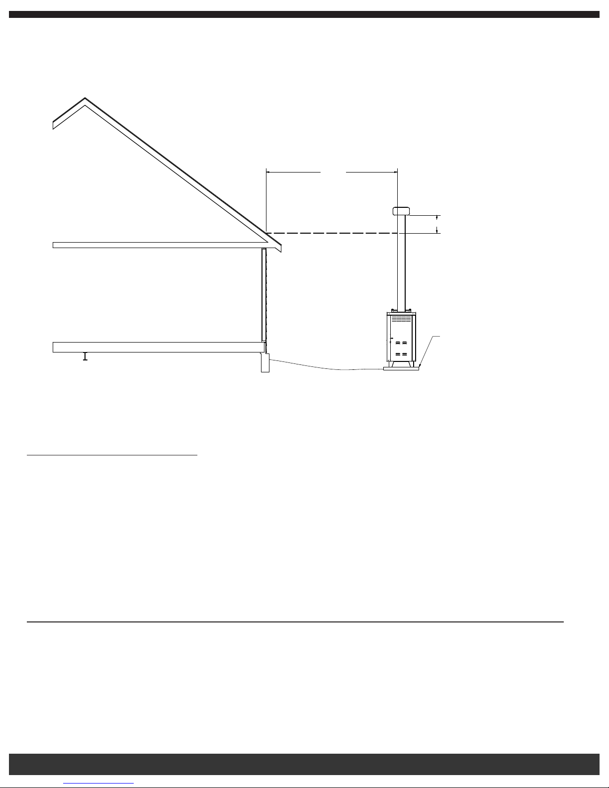
the length of the measurement increases. Once this measurement reaches 10 feet, this height on the chimney is your base height. The
chimney must be 2 feet taller than the base height. If the chimney is closer than 10 feet from the peak of the roof, the chimney must be 2
feet higher than the peak of the roof. The 2 feet above the base height does not include the cap. The furnace must be placed on a level,
non-combustible surface or 4 foot x 8 foot concrete pad. Do not level from top of furnace. The front is 1/2” taller than the back for water
run off. See diagram below.
10 FEET
10 Feet
2 FEET MINIMUM
2 Foot Minimum
4’ x 8’
4' X 8'
Level Concrete Pad
LEVEL CONCRETE PAD
By denition, “Class A” refers to either a lined masonry chimney or all fuel factory-built chimney. Although experts have expressed
differing opinions as to which system is the best, it is a matter of what you nd most suitable. Regardless of your choice of chimney type,
a minimum 6-inch diameter chimney is needed. In order to create the most efcient draft, the chimney size should not exceed 12 inches,
with a maximum .08-inch water column draft. The ue draft can be measured with the use of a draft gage or manometer.
Wood Storage and Care:
KEEP WOOD COVERED AT ALL TIMES. This cannot be over emphasized. Wood stored/stacked, uncovered, exposed to rain and
snow has a higher moisture content, causing the formation of creosote, excess smoke, and it takes longer to ignite as well as producing
poorer res with lower sustained BTU output. Unseasoned wood ends up costing more in time trying to achieve and maintain proper
temperatures in the rebox, while using more wood with less heat output. Covering the woodpile will keep it dry and offer you the hottest
res with the greatest BTU output. If you store the wood near your furnace, be sure to maintain proper clearance from the furnace to
prevent a re hazard. DRY WOOD WILL PRODUCE HOTTER FIRES AND INCREASE BTU OUTPUT.
IMPORTANT: FOR TECHNICAL SUPPORT OR CUSTOMER SERVICE
ISSUES, DO NOT RETURN TO THE DEALER (THE DEALER DOES NOT HAVE
REPLACEMENT PARTS), CALL FIRE CHIEF AT 1-800-875-4788.
Furnace Installation
• Installation is to be performed by a qualied installer.
• Always consult local building inspectors for codes concerning the installation of your furnace.
• Always have access to a backup generator, 2000 watt minimum.
• Use Class “A” HT 2100 All Fuel 6 Inch Chimney for your Fire Chief Furnace.
• Never use galvanized pipe in your ue connection.
• Inspect the ue periodically for structural integrity.
7
Page 9
• Clean the ue regularly to prevent creosote accumulation.
• Never use chemicals or gasoline to start or maintain your re.
• Never burn garbage, oil, trash, or gasoline in your furnace.
• Never leave the fuel door or ash drawer open during operation.
• Remove ashes on a daily basis, before ashes reach the grates, to ensure proper air ow.
• Never use wet, unseasoned wood or wood exposed to a recent rainfall. Doing so causes a rapid accumulation of hazardous
creosote, which is a proven cause of ue res.
• Never burn plastics, wood products containing glue, or wood that has been treated with chemical preservatives in your
Fire Chief Furnace. The combustion of these substances may release harmful, toxic gases.
• NEVER UNPLUG THE FURNACE FROM THE POWER SOURCE. THIS WILL CAUSE THE FURNACE TO OVERHEAT. If it
is too warm in the house, lower the temperature on the thermostat; reduce the spin draft to allow less airow into the rebox;
and/or use less fuel (wood or coal).
• Never leave the ash drawer or fuel door open in an attempt to regulate the re. This will overheat the furnace and void
the warranty.
• Do not connect this unit to a chimney ue serving another appliance.
• Refer to nameplate on furnace for additional information.
WARNING: RISK OF FIRE
• DO NOT operate with ue draft exceeding .08 water column inches (19.9 Pa).
• DO NOT store fuel or other combustible materials within marked installation clearances.
• Inspect and clean ues and chimney regularly.
• DO NOT operate your furnace with the fuel door or ash drawer open.
DANGER: Risk of Fire and Explosion. Do not burn garbage, gasoline, naphtha, engine oil, or other ammable liquids/inappropriate
materials.
Installing Electrical Components:
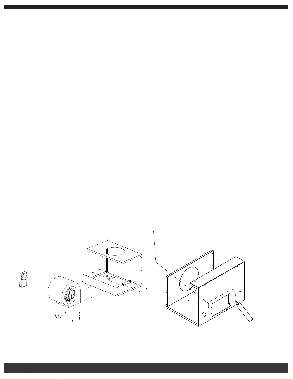
1. Install the blower onto brackets located on the blower housing using four 1/4”-20 bolts and four 1/4” U nuts (provided).
2. Caulk the blower housing and attach to back of furnace using two 1/4”- 20 bolts and two 1/4” nuts. (See diagram)
1
4 BEAD OF
DETAIL A
SCALE 2 : 1
Place a 1/4 inch bead of high-temp silicone
PLACE A
along dotted path shown
SILICONE RTV ALONG
DOTTED PATH SHOWN
A
Note: To help in the installation, lay part face down (bracket side down) to allow blower to be assembled.
8
Page 10
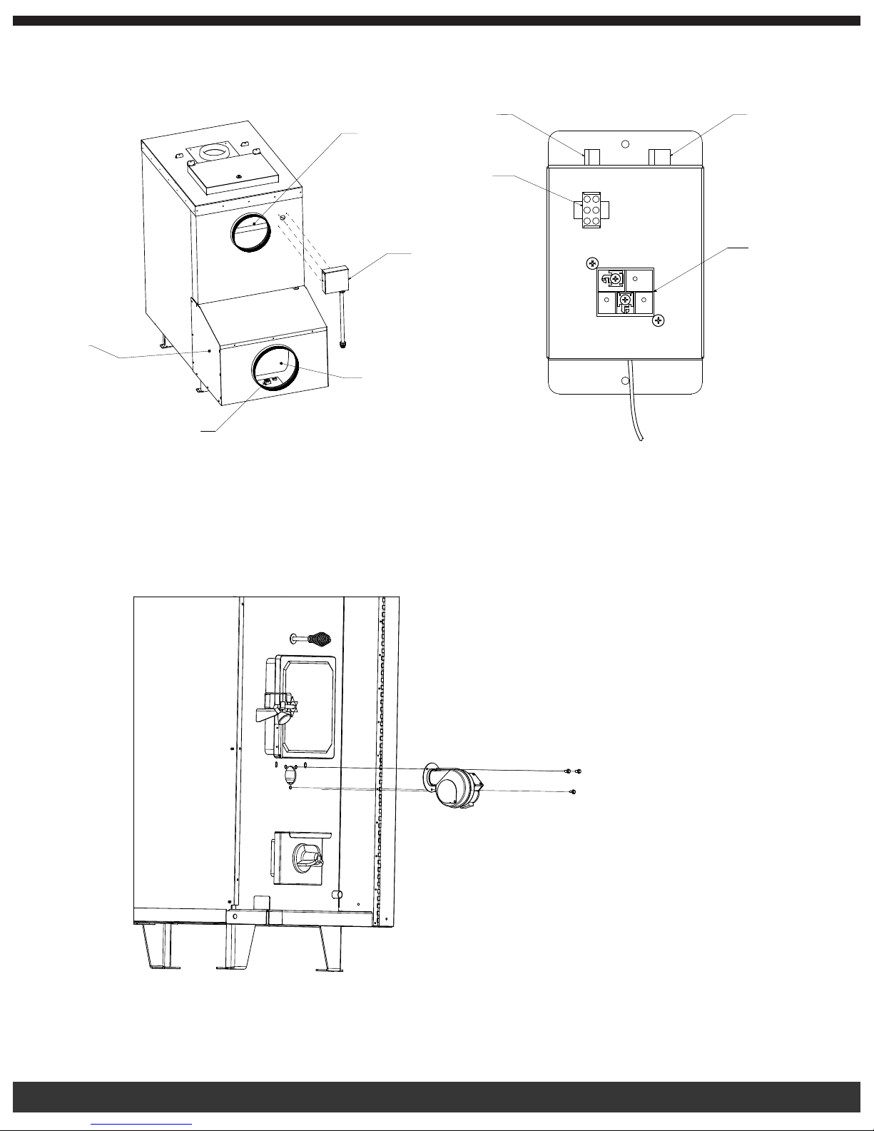
3. Align the fan limit control box with the gasket to the 4 holes on the back of the furnace with four #10 x ¾” screws for a
watertight seal.
Fan
Limit
Transformer for
Thermostat Wire
Blower
Service
Cover
Electrical Control Center
(See Close-Up Diagram)
Hot Air Supply
Cold Air
Return
Draft
Motor
Blower
Motor
Fan Limit
Control
4. GROUND FURNACE TO GROUNDING ROD AND LEG OF FURNACE!
5. Mount blower service cover using 23 #10 screws.
6. Pass the wire conduit through the hole on the blower housing. Reinstall the locking nut on weather tight tting.
7. Mount draft motor to the front of the unit using (3) 3/4” bolts. Pass conduit through tube located on lower right corner. Attach
conduit clip with one #10 x ¾” screw to right inner panel. Insert plug into control center receptacle marked “draft motor.”
STEP 6
8. Insert the plug from the fan limit control into the control center receptacle marked “fan limit.”
9. Insert the plug from the blower motor into the control center receptacle marked “blower motor.”
9
Page 11

10. Mount cover on fan limit control box with two #10 screws.
11. Caulk blower housing cover seams. For 8-10, see diagram under #3 above.
Run the thermostat wire (not supplied) from the 2 posts located on top of the control center transformer. NOTE: You may run the
thermostat wire and power cord through the return cold air duct, or you may access the hole from the bottom of the blower housing cover.
THE HOLE MUST BE SEALED AFTERWARD, REGARDLESS OF ROUTING CHOICE. AN AIRTIGHT SEAL IS REQUIRED, OR THE
BLOWER MOTOR WILL DRAW IN OUTSIDE COLD AIR. THIS WILL REDUCE THE HEATING EFFICIENCY OF THE FURNACE, AND
MAY CAUSE A SHORT CYCLING EFFECT.
Connect the 10 inch starter collar to the heat supply vent of the furnace. Connect the 12 inch starter collar to the cold air return on the
back of the blower housing cover.
NOTE: When installing blower housing to the back of the furnace, we suggest that you support the bottom of the blower housing
approximately 6 ¼ inches from ground level to allow for easier mounting of the blower housing cover.
Hot Air Duct and Cold Air Return Installation:
Included with your Fire Chief Furnace:
• Two 10 inch starter collars
• One 12 inch starter collar
If using 10 inch insulated ex hot air duct, it is for indoor use only. Outside the house, you must use 10 inch galvanized pipe, wrapped
with weatherproof UV-jacketed insulation for protection from the sun’s UV rays. The 12 inch return air may be galvanized pipe. The
12 inch return air must be attached to the home so as not to pressurize the home. The warm air supply duct should be constructed of
materials with a minimum temperature rating of 250° Fahrenheit.
NEVER reduce the 10 inch hot air or 12 inch return air, as this will affect the air ow and the furnace will not operate properly.
NEVER draw cold outside air into the blower housing. By doing so, the furnace’s heat chamber will not reach the necessary temperature
to heat the home.
The duct work should be designed so the external static pressure does not exceed .02 water column inches, while developing air
velocities of 600 feet to 1,000 feet per minute in the main trunk duct and 400 feet to 600 feet per minute at the registers. The heat outlet
should never be less than 10 inches round or 79 square inches.
The Fire Chief Furnace must be installed with a cold air return system. The system must be a minimum of 12 inches to readily transfer
the cold air back to the furnace. If desired, a cold air lter box may be constructed with a minimum opening of 225 square inches.
A basement window is an excellent location for running the hot air duct vent as well as the vent for the cold air return. The cold air return
is an integral part of the system and must be used when installing the furnace. Failure to use cold air return will pressurize the home
causing the furnace to not work properly. If a basement window is not available, you may access the home through a window, wall, or
crawl space for both the plenum and air return.
Burying Ductwork:
DO NOT BURY FLEXIBLE DUCT.
To bury the ductwork, use schedule 40 or 80 PVC or black plastic DUAL WALL CULVERT PIPE with smooth inner walls. Dig a trench to
accommodate both the heat duct and the return air duct. The trench must be a minimum of 24 inches deep. To further ensure efciency,
minimize heat loss, and prevent moisture formation, line the trench with 1 inch pink Styrofoam insulation sheeting on the sides and
bottom of the trench. The duct run should not exceed 25 feet. If the run exceeds 25 feet, you run the risk of reducing the furnace’s
efciency and airow.
DO NOT USE FLEXIBLE HOT AIR DUCT INSIDE PVC OR CULVERT PIPE.
ALWAYS KEEP YOUR WOOD COVERED YEAR ROUND. DRY WOOD WILL PRODUCE MORE BTU OUTPUT AND A LONGER BURN
TIME.
*BE SURE TO KEEP WOOD COVERED YEAR ROUND!*
10
Page 12
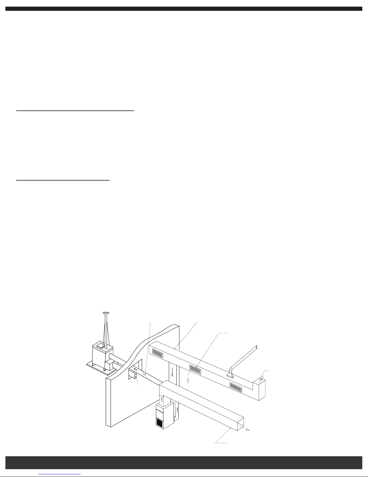
The diagram below shows typical installations through a basement window, crawl space, or wall. Notice that the heat duct and return air
duct do not contain any 90° elbows. The use of 45° or less is advised for proper air delivery.
IF 10 INCH FLEX DUCT IS USED, IT MUST NOT BE EXPOSED TO THE OUTDOORS. IT IS FOR INDOOR USE ONLY.
WARNING: RISK OF FIRE! DO NOT USE ANYTHING OTHER THAN 250° F-RATED FLEX DUCT!
IMPORTANT: FOR TECHNICAL SUPPORT OR CUSTOMER SERVICE
ISSUES, DO NOT RETURN TO THE DEALER (THE DEALER DOES NOT HAVE
REPLACEMENT PARTS), CALL FIRE CHIEF AT 1-800-875-4788.
TYPES OF INSTALLATIONS:
Your Fire Chief Furnace is designed to be a supplemental or central heating source for your home. This wood/coal burning furnace may
be installed in parallel with a properly operating electric, gas, or oil-red central furnace that is listed or certied in accordance with a
nationally recognized safety standard within installation clearances as specied on the Fire Chief Furnace nameplate. When in a parallel
installation the static pressure of the central furnace plenum may not exceed .15 water column inches, and the maximum setting on
central furnace limit switch is 182° F. With the FCOS1800D and FCOS2200D wood and coal burning furnaces in an “Interconnection
Arrangement” your Fire Chief Furnace should be upstream from the central furnace. The Fire Chief Furnace warm air supply should
never be connected to the return air for the central furnace. A QUALIFIED INSTALLER SHOULD PERFORM INSTALLATION.
CENTRAL DUCT CONNECTIONS: A qualied professional should do the installation. Maximum run should be 25 feet. A duct run in
excess of 25 feet will greatly restrict the air ow and heat output, therefore is not recommended. When connecting the Fire Chief Furnace
to a central duct system, avoid 90° elbows. As with any furnace, the more turns and branches in the ducting limit the airow delivery. DO
NOT USE FLEX DUCT OUTSIDE.
Run 10 inch insulated galvanized hot air duct from the outside furnace through a window or wall of the house. Once inside, you may use
250º Fahrenheit rated insulated exible hot air duct to connect the central duct system for the home. When using exible duct inside the
home, it must be pulled tight with no offsets or elbows to prevent turbulence and slowdown airow. Connect the duct with a 45° elbow
or at an angle so the hot air from the Fire Chief Furnace is delivered down stream. This will ensure proper airow into the duct system.
Avoid delivering the hot air through the air conditioning coil, as this will cause an obstruction, reducing the amount of heat output. DO
NOT REDUCE THE SIZE OF THE HOT AIR DUCT. As with any furnace, longer runs and more turns and branches in the ducting greatly
reduce the airow and heat output. Use of 90° elbows is not recommended.
The 12 inch cold air return duct must run to the house to prevent pressurization of the home. Failure to connect the cold air return will
cause the furnace not to operate. NEVER REDUCE THE SIZE OF THE RETURN. Reducing the size of the cold air return will restrict
the hot air ow and put excess pressure on the blower motor. You may terminate the cold air return where you enter the house. This will
provide adequate circulation within the home. See diagram.
RETURN AIR DUCT
Backdraft Damper
BACKDRAFT DAMPER
Return Air Duct
Open/Close
OPEN/CLOSE
Return Dampers
RETURN DAMPERS
3 Places
3 PLACES
11
SUPPLY DUCT
Supply Duct
Page 13
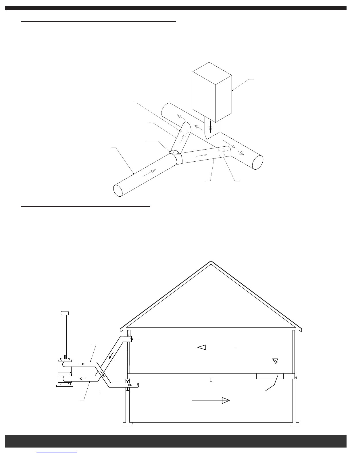
MOBILE HOME DOWN DRAFT FURNACE CONNECTIONS: A qualied professional should do the installation. Maximum duct
run is 25 feet, a duct run in excess of 25 feet will greatly restrict the air ow and heat output and is not recommended. Both the hot air
duct and the cold air return duct may be accessed through the oor in a mobile or modular home. In a mobile home with a down draft
furnace, do not attach the hot air duct from the Fire Chief Furnace to the hot air plenum, doing so will cause the heat to rise through the
central furnace instead of going through the duct work. Split the hot air supply for the Fire Chief Furnace by using a “Y” and install one
branch into each of the hot air ducts. Be sure both are pointing downstream. See diagram.
Existing Downdraft
EXISTING DOWNDRAFT
FURNACE
Furnace
8” Back Draft Damper
8" BACK DRAFT DAMPER
8 Inch Diameter
8 INCH DIAMETER,
MINIMUM
Minimum
10” to 8”
10" TO 8"
Y-TEE
Hot Air Duct from
HOT AIR DUCT FROM
OUTDOOR FURNACE
Outdoor Furnace
Y-tee
8 Inch Diameter
8 INCH DIAMETER,
Minimum
MINIMUM
8” Back Draft Damper
8 " BACK DRAFT DAMPER
NO DUCT WORK INSTALLATION CONNECTION: A qualied professional should do the installation. Cold air return must be
installed in all cases, even those without ductwork. When there is no duct system to connect to the hot air ex duct, keep in mind:
• You must separate the hot air duct from the cold air return. Ideally, locate each at opposite ends of the home. If you don’t, the
air will not ow evenly throughout the home. This method will work well on homes built on concrete slabs and help create a
good airow.
• In homes with a basement, you may run the hot air duct into the basement and pull the cold air return from the main oor, this
will create a perfect air ow, since hot air rises. The cold air return must be connected, even if the home does not have
ductwork. If you don’t connect the cold air return, the furnace will not be able to heat the home. See diagram.
Hot Air
HOT AIR
Cold Air
COLD AIR
12
Page 14
Outside Combustion air may be necessary for an indoor installation if:
• The solid-fuel-red appliance does not draw steadily, smells, experiences smoke rollout, burns poorly, or back-drafts whether
or not there is combustion present. Opening a window slightly on a calm day alleviates these symptoms.
• The house is equipped with a well-sealed vapor barrier and tight tting windows, and/or has any powered devices, which
exhaust house air.
• There is excessive condensation on windows in the winter.
• A ventilation system is installed in the house.
CAUTION: HOT SURFACES. KEEP CHILDREN AWAY. DO NOT TOUCH DURING OPERATION.
BURN WOOD AND COAL ONLY!
General Operation:
First Wood Fire:
Set the wall thermostat to 90°F. Check to make sure the spin draft is wide open to allow oxygen into the rebox. Make sure switch on the
wall thermostat is in the HEAT position. Adjust slide cover on draft blower to an opening of approximately ⅜ inches.
Place several crumpled newspapers on the grate with some dry kindling layered on top of the papers, then ignite the newspaper. When
the kindling is burning, add several small pieces of wood, allow wood to fully ignite. After about 20 minutes the re should be established,
allowing you to add more wood – do not overload which would smother the re. Add more wood slowly, so the ames have time to engulf
the fresh wood. Once the re is burning and there is a glowing ember bed, adjust the draft to achieve desired burn pattern. Learning
how to adjust the draft to maintain the desired temperature for your home may take several days. After a short time you will know which
settings and adjustments work best for your home. Set the wall thermostat to the desired home temperature.
Do not over-re the furnace. Over-ring by overloading/over fueling the furnace causes the metal to superheat and expand, then cool
rapidly, which causes cracking, therefore voiding the warranty. Over-ring or abuse can easily be determined upon inspection.
It will take about 40 minutes to establish a bed of hot embers. Once you have achieved the hot ember bed, add larger pieces of rewood
and push the bypass rod all the way in. Within 30 to 40 minutes, adjust the spin draft to obtain optimum performance. Finally adjust the
wall thermostat and draft blower cover to a comfortable setting. See diagram on page 16.
NOTE: Your new Fire Chief Furnace is capable of producing a very high BTU output. Do not fuel your furnace to capacity upon initial
ring. It’s recommended that you become thoroughly familiar with your Fire Chief Furnace before operating at full capacity.
The new steel and metal components of the furnace have a protective coating or paint on the surface which could produce an odor during
the break in period. Adequate ventilation within the home and furnace room or area is recommended during the initial ring and break
in period to accommodate this possibility. Your new Fire Chief Furnace is classied as having airtight construction. This type of design
should enable you to experience an average burn time between 6 and 12 hours per full load of fuel (dry, seasoned hardwood). However,
abnormally cold weather may reduce the burn time somewhat, but if your burn cycle is signicantly less, for instance, 2 to 4 hours, you
are over-ring your furnace. This type of occurrence is usually symptomatic of heat demands in excess of furnace capacity. Contact an
authorized professional to determine if your Fire Chief Furnace has been improperly sized for your home.
Loading Wood:
When opening the fuel door during operation, always pull the bypass rod all the way out before opening the fuel door, wait 10 seconds
after releasing the rst latch, then open the door the rest of the way. The dual latch system has been incorporated as a safety feature,
designed to reduce the possibility of gaseous ignition. Laboratory testing has determined that when incomplete combustion occurs
the partially spent fuel sometimes concentrates large amounts of potentially hazardous gases within the re chamber. If the door is
opened suddenly under these conditions, the oxygen may combine with these gases and cause ignition referred to as “back ash.” Use
EXTREME CAUTION when opening the fuel door.
When reloading the furnace, spread embers evenly over the grate. Place smaller pieces of wood or coal on the hot embers and layer
larger pieces on top of them. Finally, due to the wide variety of temperature ranges during the winter, you may experience periods when
it is not necessary to fully load the re chamber in order to maintain an overnight burn. Your Fire Chief Furnace will operate at the highest
efciency by adding fuel in amounts needed to maintain comfortable temperatures in your home.
13
Page 15
IMPORTANT: FOR TECHNICAL SUPPORT OR CUSTOMER SERVICE
ISSUES, DO NOT RETURN TO THE DEALER (THE DEALER DOES NOT HAVE
REPLACEMENT PARTS), CALL FIRE CHIEF AT 1-800-875-4788.
First Coal Fire:
Burning coal is much harder than burning wood. There is more care and work in building and maintaining a coal re than a wood re.
Anthracite is the best coal to burn, due to its long even burn with higher heat output and clean burn quality but is more difcult than
Bituminous coal.
The size of coal is important. “Nut” coal sizes of 4 inches for Bituminous and 2¾ to 4½ inches for Anthracite coal are recommended.
Never use coal other than the sizes recommended. If the coal is too small it will smother the re and if it is too large the coal will not burn
well.
When burning Bituminous coal, start the re with wood (as described above). Always use dry kindling, as this will provide a hotter re
and add small pieces of wood until you get a good hot ember bed. At this point add a small amount of coal. When the coal is hot enough
to ignite, add small amounts at a time, so as not to smother the re. Keep in mind that Bituminous coal will require more maintenance as
this type of coal will produce more soot, requiring more frequent cleaning to prevent buildup.
Also make sure that the spin draft control is wide open to establish the correct burn pattern. When adding coal to Bituminous res always
add coal to the center of the bed creating the cone effect. Bituminous coal is more volatile and adding coal to the center of the bed
causes the ames to drive off the volatile gases. Remember that no two installations and chimney set-ups are the same, so be prepared
to experiment until you achieve the desired results. Always allow enough air to the rebox so that volatile gases are properly burned.
When adding fuel, remember to break up the cone with a poker if it has formed a crust, but be careful to avoid mixing the coal as this
can form clinkers. Shake the grates a couple times so as not to disturb the re. Excessive shaking wastes fuel and exposes the grate to
extreme heat, which will cause warping or burnout. For overnight burn operations, follow the above instructions and adjust the chimney
damper and set the thermostat.
When burning Anthracite coal, start the re with wood (as described above). Add layers of coal making sure not to smother the re,
the third layer should be a little heavier, but should not to extend above 2 inches below the top of the brick in the rebox. Before
adding more fuel, be sure to leave a red spot in the center of the bed. This hot spot will help ignite the gases given off the new charge.
A deep charge will give a more even heat and a longer re. It may take up to a couple hours before the whole bed is fully ignited. When
the re is established and the home is becoming warm, you may adjust the damper. It may still take some experimenting with the wall
thermostat to ensure proper operation, as no two installations are the same. Once the coal bed has reduced to half its original depth it
is time to add fuel to the furnace. At this point pull out the bypass rod and turn up the wall thermostat. This will allow the re to burn off
the accumulated gases. Open the fuel door, using a small rake or hoe pull the coals towards the front of the bed, trying not to disturb the
re too much. Next, add coal to the back, being careful not to seal off the top. Keep the ash drawer cleaned out to ensure good airow.
You may want to start this banking process early in the evening before retiring or before leaving the home so that you may make proper
adjustments after the re is well established.
WARNING: It is unsafe to load any type of coal within 2 inches of the top of the rebrick. Load fuel carefully or damage may result.
NOTE: Do not burn coke, charcoal, highly volatile Bituminous coal, sub Bituminous, lignite or cannel coal (sometimes called channel
coal or candle coal). Never burn wax or chemically processed logs, such as re logs as their use is for replaces only. Please follow all
guidelines in this manual concerning wood and coal burning applications due to safety concerns and to maintain warranty coverage.
BURN WOOD AND COAL ONLY!
Fuel Recommendations:
For the FCOS1800D and FCOS2200D models, heat resistant gloves are recommended when loading the furnace. Only use dry,
seasoned hardwoods in your Fire Chief Furnace rather than high resin woods such as pine. Firewood should be cut at least one full
season prior to the time of its intended use for optimum heat output. Firewood should be stacked to provide a free ow of air between
the logs; this allows the wood to season faster. If wood is stored outdoors, it should be completely covered year round to protect it from
moisture and exposure to the elements. Use extreme caution when opening the ash drawer and fuel door during operation, temperatures
can exceed 300° F. Wait at least 10 seconds after releasing the rst latch, then proceed to the fully open position. The dual latch system
has been incorporated as a safety feature, which was designed to reduce the possibility of gaseous ignition. Heat resistant gloves are
14
Page 16
recommended when opening the fuel door, regulating the spin draft or emptying the ash pan.
DISPOSAL OF ASHES:
Heat resistant gloves are recommended. In order to remove ashes from your Fire Chief Furnace, slide the ash drawer to the rear of the
furnace. Remove the ash drawer from the furnace and dump the ashes into a metal container with a tight tting lid. The closed container
of ashes should be placed on a non-combustible oor or on the ground, well away from all combustible materials, pending nal disposal.
If the ashes are disposed of by burial in soil or otherwise locally dispersed, they should be retained in the closed metal container until
all cinders have thoroughly cooled. Remove the ashes from your Fire Chief Furnace at least once a day, or as often as necessary to
ensure the ashes do not accumulate to the height of the grates. If ash build-up occurs at grate level, it will cause premature failure of
the grate system, voiding the warranty on the grates. Unacceptably high temperatures will result because the ashes have restricted the
ow of cooling air beneath the grates. This ow of air was designed to not only cool the grates, but to also provide warmed air for better
combustion. If the ash level is improperly maintained the rebox will be starved of combustion air, greatly reducing the efciency and heat
output of your Fire Chief Furnace.
ALWAYS KEEP YOUR WOOD COVERED YEAR ROUND. DRY WOOD WILL PRODUCE A HIGHER BTU OUTPUT AND A LONGER
BURN TIME.
HEAT DUMP AND FUSE LINK SYSTEM:
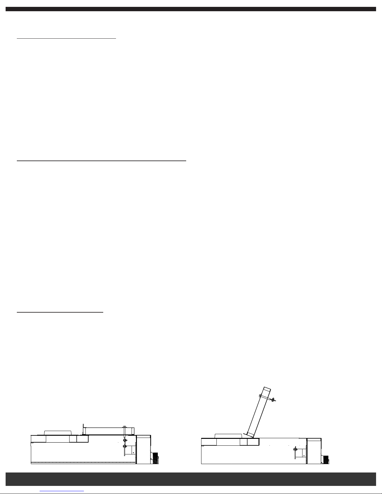
The Fire Chief Furnace has a patented automatic safety feature, the Heat Dump Release System. In the case of a power failure, the heat
dump release will open the spring-loaded lid when the internal furnace temperature reaches 370° F. The heat sensitive fuse link, located
within the top of the heat chamber, causes the lid to open, allowing the excess heat to escape. This safety feature is designed to activate
before any extreme heat can damage the furnace.
In the case of a power failure, connect your Fire Chief Furnace to a generator immediately. If the heat dump release lid should open, do
not continue to burn the furnace. DO NOT UNPLUG THE FURNACE. Close the draft dampers and set the wall thermostat to the lowest
possible temperature. DO NOT add fuel (either wood or coal), which will allow the re to die. Pull out by pass rod. After the electricity is
restored, replace the fuse link before resuming normal operation.
Caution: If your heat dump opens without a power failure here is a list of possible reasons:
1). To many elbows in your duct runs
2). Reducing the size of your duct runs
3). Running your gas/electric furnace blower in the on position.
This will create resistance in the hot air duct run thus causing the fuselink to melt under normal operating conditions without a power
failure.
REPLACING THE FUSE LINK: Remove the hex nut on top of the release lid and pull the bolt down through the lid. Remove the
separated fuse link pieces and connect the new fuse link to the shaft inside the furnace heat chamber. Connect the other end of the
fuse link to the bolt that goes through the lid. Feed the bolt through the lid and replace the hex nut onto the bolt on top of the lid. As a
precaution, always have a replacement fuse link on hand.
WARNING: Never disengage the patented Heat Dump Fuse Link feature. This will void all warranties. Never put anything on top of the
release lid. The area must be kept free of any obstructions. A visual inspection by factory personnel can easily determine if the proper
steps were taken if a furnace over-heats. If the furnace is found to be deliberately improperly used, all warranties will be void.
CLOSED
15
OPEN
Page 17
To order a replacement Fuse Link (Part # FCFL370): call 1-800-875-4788.
One replacement fuse link was included in the hardware pack for your furnace.
Draft Blower and Spin Draft:
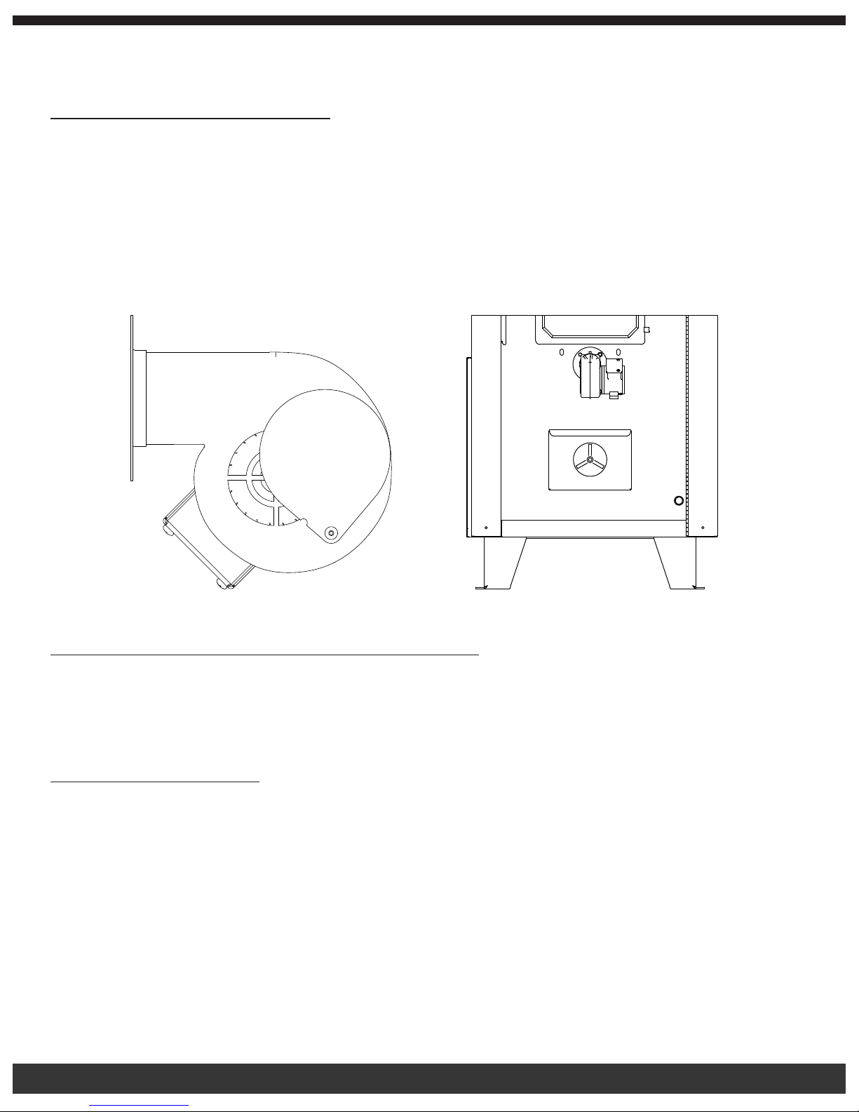
The front draft blower plays an important role in the operation of your Fire Chief Furnace. When the wall thermostat calls for heat, the
draft motor turns on and supplies fresh air into the rebox producing a hotter re, which in turn provides more heat in the heat chamber.
The heat is then sent through the duct system throughout your home. When the wall thermostat temperature is met, the draft blower
shuts off until the thermostat calls for heat, beginning the cycle again. The draft blower has a slide cover located on the side of the
motor that is factory preset, with an opening of approximately 3/8”. The cover should be fully closed only when there is a power failure
and electricity is lost. With the cover closed, no air is introduced into the rebox, then the re dies, preventing the furnace from possible
overheating and damage. The manual combustion air spin damper control on the ash drawer should be set with a 1/8 inch gap. To
begin, adjust slowly by making 1 rotation at a time to nd the correct air setting.
Slide Cover to
Make Adjustment
Creosote Formation and Need for Removal:
When wood is burned slowly, it produces compounds in exhaust smoke, which combine with expelled moisture to form creosote. The
creosote vapors condense in the relatively cooled chimney ue of a slow burning re. As a result, creosote residue accumulates on the
ue lining. When ignited, this creosote makes an extremely dangerous re in the chimney. The chimney connector and the chimney
should be inspected at least twice monthly during the heating season to determine if a creosote build-up has occurred. If creosote has
accumulated it should be removed to reduce risk of a chimney re.
Creosote Prevention:
To help prevent the formation of creosote within the ue, ALWAYS BURN DRY, SEASONED WOOD. Dry wood burns hotter, allowing ue
gases to maintain temperatures above 212°F which should reduce the formation of creosote in the chimney. If the ue gas temperature
falls below 212°F, condensation occurs causing creosote formation and accumulation within the chimney.
As an added precaution, periodic chimney inspections are recommended during the heating season to determine if creosote formation
has occurred. For safety and efciency, it is recommended that the chimney system be inspected and cleaned prior to each heating
season.
*BE SURE TO KEEP WOOD COVERED YEAR ROUND!*
16
Page 18
Power Failure:
In case of power failure, to prevent your Fire Chief Furnace from over-heating and causing damage to the electrical components, follow
these steps:
• Ensure that the bypass rod is pulled out, allowing heat to go up the chimney.
• Close the spin damper control on the ash drawer.
• Close the slide cover on the side of the draft motor.
• Do NOT add more fuel (coal or wood) to the rebox.
There is no warranty on electrical components damaged due to power failure.
CAUTION:
• INSPECT FLUE PIPES, FIREBOX, STOVE PIPE, CHIMNEY AND DRAFT BLOWER JOINTS AND SEALS REGULARLY TO
ENSURE THAT SMOKE AND FLUE GASES ARE NOT DRAWING INTO, AND CIRCULATED BY THE
AIR-CIRCULATION SYSTEM.
• CLEANING OF THE FIREBOX, STOVE PIPE, CHIMNEY AND DRAFT BLOWER (IF USED), IS ESPECIALLY IMPORTANT
AT THE END OF THE HEATING SEASON TO MINIMIZE CORROSION DURING THE SUMMER MONTHS CAUSED BY
THE ACCUMULATED ASH.
• Do not use chemicals to start the re.
• Do not burn garbage, gasoline, naphtha, engine oil, or other ammable liquids/inappropriate materials.
Maintaining Your Furnace:
At the beginning of each heating season, take time to thoroughly check your furnace and chimney system. Make sure there are no
leaks where the metal panels are joined or at the caulk lines. Should you nd a leak, high-temp silicone will correct the problem. Check
the door for signs of rust. Should rust develop, lightly sand, with sandpaper or steel wool, the surface and follow up with black, high
temperature paint to keep the door looking new. Check the gaskets, if they are frayed and burnt, replace the gasket. Check the rebricks
for breakage or crumbling, and replace as needed. Check the chimney pipe for signs of creosote formation, if you nd creosote,
thoroughly clean the chimney system replacing the chimney cap securely so rain or snow does not run down the chimney into the rebox.
If the cap is removed for any length of time when the furnace is not in use, cover the pipe so no moisture gets into the rebox. Check the
chimney cap for holes or loosened connections, replace and secure as necessary. Check the grates for signs of wear and replace as
needed. Check the heat duct and cold air return to be sure they have not become loose or been damaged. If so, tighten or replace as
needed. Check ductwork for any air leaks. Remove any accumulated ashes at the end of the season. By following these procedures,
your furnace will provide many years of trouble-free service.
IMPORTANT: FOR TECHNICAL SUPPORT OR CUSTOMER SERVICE
ISSUES, DO NOT RETURN TO THE DEALER (THE DEALER DOES NOT HAVE
REPLACEMENT PARTS), CALL FIRE CHIEF AT 1-800-875-4788.
ALWAYS:
• Locate the Fire Chief Furnace on a level, solid, non-combustible surface.
• Follow local codes concerning installation requirements.
• Connect power cord to a grounded 110 outlet.
• Connect cold air return to the house.
• Use Class “A” HT2100 All Fuel 6 inch chimney.
• Follow guidelines within this manual regarding burn procedures.
• Operate furnace with fuel door and ash drawer closed.
• Inspect the furnace several times a year to ensure furnace caulking is adequate.
• Inspect chimney pipe for creosote formation.
• Use dry, seasoned hardwood and always keep your wood covered.
• Have access to a backup generator in case of power failure, minimum of 2000 watts.
NEVER:
• Allow anyone to operate the furnace that is not familiar with the unit.
• Operate the furnace with the spin draft wide open unattended.
17
Page 19

• Operate with fuel door or ash drawer open.
• Use gasoline, oil, or any other ammable liquid to start or maintain the re.
• Burn garbage, plastic, wood containing glue or wood that has been treated with chemical preservatives.
• Operate your furnace without a backup power supply, or generator.
• Fuel your furnace with wet, unseasoned wood.
• Use 90° elbows when running ductwork.
• Operate the furnace without the chimney attached.
• Alter the furnace in any way.
CAUTION: HOT SURFACES. KEEP CHILDREN AWAY. DO NOT TOUCH DURING OPERATION.
CAUTION:
• INSPECT FLUE PIPES, JOINTS AND SEALS REGULARLY TO ENSURE THAT SMOKE AND FLUE GASES ARE
NOT DRAWING INTO, AND ARE NOT BEING CIRCULATED BY THE AIR-CIRCULATION SYSTEM.
• CLEANING OF THE FIREBOX, STOVE PIPE, CHIMNEY AND DRAFT BLOWER (IF USED), IS ESPECIALLY IMPORTANT
AT THE END OF THE HEATING SEASON TO MINIMIZE CORROSION DURING THE SUMMER MONTHS CAUSED BY
THE ACCUMULATED ASH.
• Never use chemicals or gasoline to start or maintain your re.
• Do not burn oil, garbage, trash, plastic, or any fuel other than wood or coal in your furnace. Doing so will void the
warranty.
• DO NOT operate your furnace with the fuel bypass rod open; the handle must be pushed all the way in (except
when refueling).
WARNING: – RISK OF FIRE
• DO NOT operate with ue draft exceeding .08 water column inches (19.9 Pa).
• DO NOT store fuel or other combustible materials within marked installation clearances.
• Inspect and clean ues and chimney regularly.
• DO NOT operate your furnace with the fuel door or ash drawer open.
Canadian Requirements for Supplemental/Add-On Furnaces
• DO NOT USE DUCT ELBOWS HAVING AN INSIDE RADIUS OF LESS THAN 6 inches (150mm) ON OIL,
ELECTRIC, OR GAS FURNACES.
• DO NOT CONNECT TO A DOWNFLOW FURNACE.
• DO NOT CONNECT DUCTWORK SO THAT A REVERSE FLOW IS POSSIBLE.
• OPERATE THE GAS/OIL/ELECTRIC/ FURNACE PERIODICALLY TO ENSURE THAT IT WILL OPERATE
SATISFACTORILY WHEN NEEDED.
• CERTIFIED FOR INSTALLATION WITH APPROPRIATE DUCTWORK CONFIGURATIONS ONLY.
• DO NOT RELOCATE OR BYPASS ANY OF THE SAFETY CONTROLS IN THE ORIGINAL GAS/OIL/ELECTRIC
FURNACE INSTALLATION.
• DO NOT CONNECT TO ANY GAS FURNACE THAT HAS NOT BEEN CERTIFIED INITIALLY AS COMPLYING
WITH CAN/CGA-2.3.
• THE OPERATION OF THE GAS FURNACE MUST BE VERIFIED FOR ACCEPTABLE OPERATION BEFORE AND
AFTER INSTALLATION OF THE ADD-ON APPLIANCE BY A GAS FITTER WHO IS RECOGNIZED BY THE
REGULATORY AUTHORITY.
• DO NOT CONNECT TO ANY GAS FURNACE THAT IS NOT EQUIPPED WITH AN AIR-CIRCULATION BLOWER,
OR TO A CHIMNEY OR VENT SERVICING A GAS FURNACE OR GAS APPLIANCE.
The add-on unit should only be installed on a furnace duct system and chimney that are in good operating condition.
On a belt-driven system, blower and motor pulleys may be changed but the electrical current owing through the motor cannot exceed the
nameplate rating. On a direct-drive system, the motor should not be changed, however, the speed of the motor may be increased. The
blower cannot be changed. This equipment should be installed, acceptable to regulatory authority, by experienced licensed personnel.
The installation should comply with requirements of CAN/CSA-B365, and changes to the installation should comply with CSA-B139 (for
oil-red), C22.1 (for electric), or CAN/CGA-B149.1 or CAN/CGA-B149.2 (for gas-red).
18
Page 20
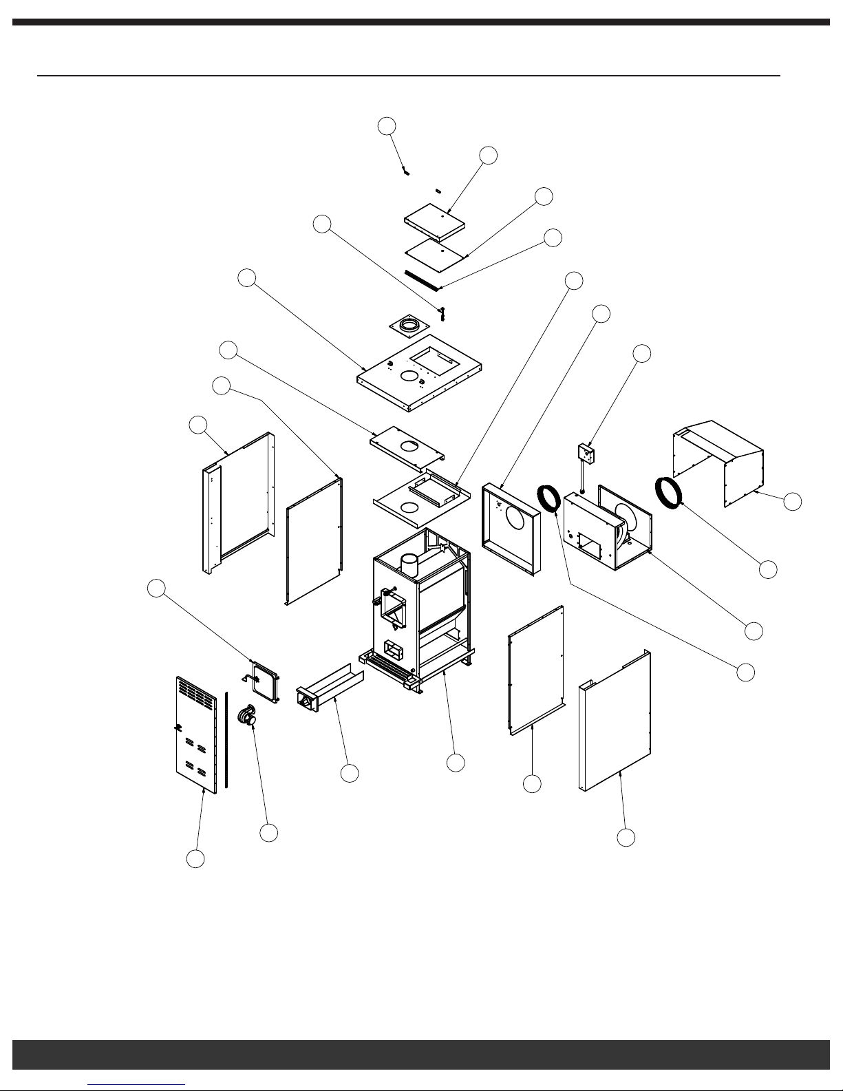
Furnace Diagram
14
)
0")
)
ANEL)
KET)
ANEL)
13
12
15
11
16
17
18
19
10
9
8
7
6
20
5
4
1
22
21
2
18
3
19
Page 21
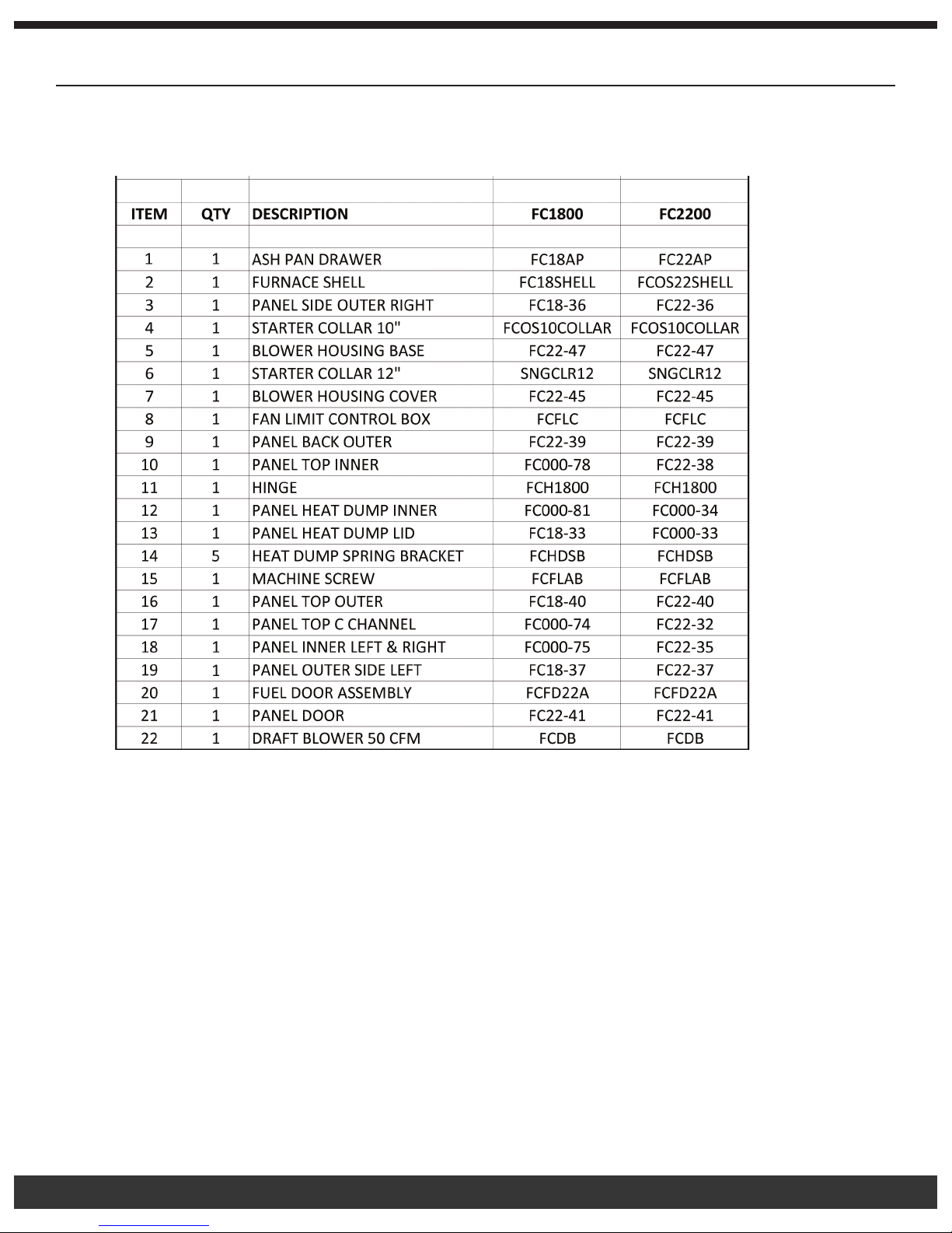
Furnace Parts List
20
Page 22
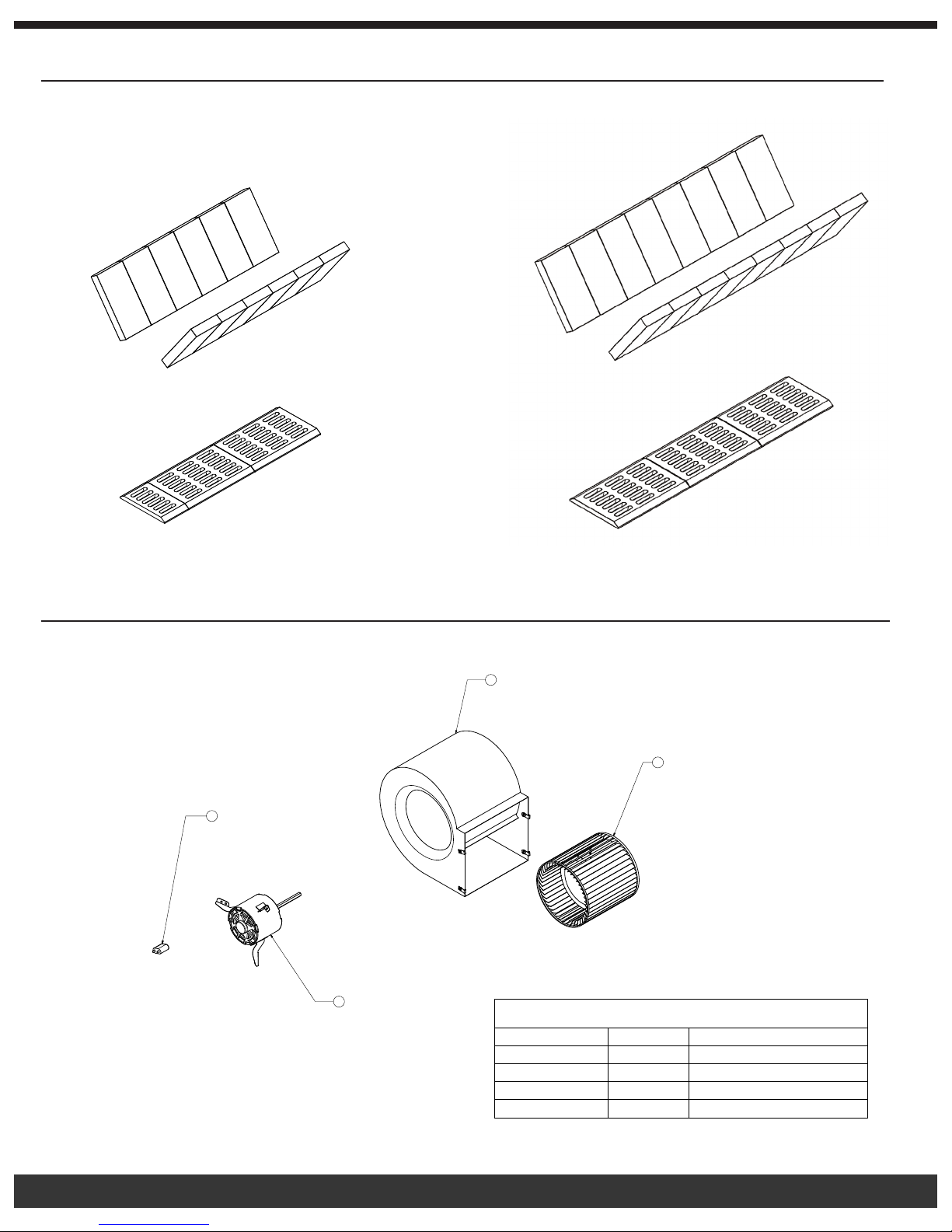
Grate and Fire Brick Diagrams
PARTS LIST
DESCRIPTIONQTY
ITEM
BLOWER WHEEL11
BLOWER HOUSING
1
2
MOTOR CAPACITOR13
BLOWER MOTOR
14
2
1
3
4
FCOS1800D FCOS2200D
Blower Motor Assembly Diagram
PARTS LIST
ITEM
DESCRIPTIONQTY
BLOWER WHEEL11
2
1
BLOWER HOUSING
MOTOR CAPACITOR13
14
BLOWER MOTOR
21
Page 23
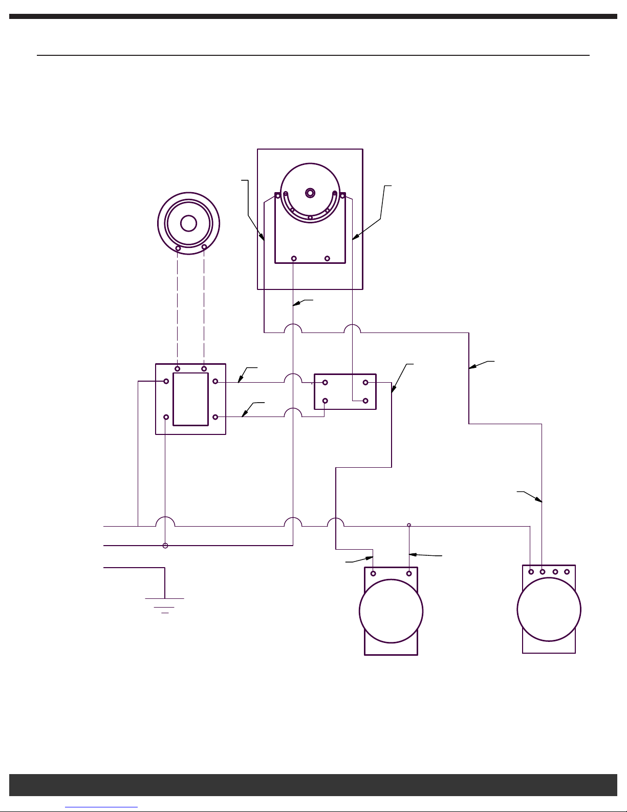
Wiring Diagram
1
2
P
WIRING DIAGRAM
OUTDOOR FURNACE
WALL
THERMOSTAT
FAN LIMIT CONTROL
ORANGE
YELLOW
BLACK
RED
RED
YELLOW
RED
RELAY
120V AC/24V AC
TRANSFORMER
BLACK 120V AC
OWER SUPPLY
WHITE
BLACK
GREEN
BLACK
DRAFT BLOWER
MOTOR
WHITE
BLOWER
MOTOR
22
Page 24
Troubleshooting
Problem: Bugs found in wood.
1.
Possible Causes:
• Wood has rotted or has been
laying around for an extended
period of time.
Problem: Home does not achieve comfortable temperature.
Remedies:
• Inspect the wood for obvious signs of insect infestation such as
burrows or holes, avoid using if possible. Do not store wood indoors.
2.
Possible Causes:
• Improper ductwork connection to
existing furnace.
Remedies:
• Refer to information in the manual relating to the proper installation
procedures or contact your local heating and cooling contractor.
• Improperly sized ducting.
• Excessive dirt accumulation in
air lter.
• Poor chimney draw, resulting in
the furnace not providing enough
heat.
• Inadequate insulation of the
home.
• Furnace size is inadequate for
your home.
• Slide cover on draft blower is
“CLOSED.”
• Fueling furnace with wet or
unseasoned wood.
• Refer to information in the manual relating to the proper ducting
procedures or consult your local heating and cooling contractor.
• Check and replace lter. Proper lter size is 20” by 25” by 1.”
• Increase height of chimney (refer to “10/2 Rule” on page 4.) This will
help the furnace to achieve more efcient and hotter temperatures.
• Provide additional insulation.
• Consult a professional to determine correct sizing.
• Open slide cover to an opening of approximately 3/8 inches.
• Completely avoid using if at all possible. If circumstances
necessitate the use of wet or unseasoned wood, then fuel the
furnace with smaller loads. This will cause the thermostat to call
for heat more often, which will initate the running of the draft
blower. Consequently, the res will be hotter, thereby reducing the
accumulation of creosote.
• Outside air is being pulled into
the return air duct, reducing the
heat output in the home..
Problem: Heat dump lid on top of furnace has opened.
3.
Possible Causes:
• Power failure.
• Furnace has over-heated and the
heat release lid has opened.
23
• Inspect return air duct from the blower housing to the home, seal
any openings with aluminum duct tape.
Remedies:
• Use backup generator as power source immediately! Replace the
heat sensitive fuse link.
• Correct the over-heating problem and restore power to the furnace.
Replace the heat sensitive fuse link before ring the furnace again.
Page 25
Problem: Draft blower will not run. NOTE: Verify that the wall thermostat is in the
“HEAT” position, and make sure batteries are installed.
4.
Possible Causes:
• Defective wall thermostat. • This can be checked by turning the thermostat to a temperature
• Wall thermostat is in the wrong
position.
• Defective transformer relay
center.
• Defective draft motor.
• Improper wiring.
Problem: Circulation blower will not turn on.
5.
Possible Causes:
• Defective fan limit control.
Remedies:
setting that is higher than the temperature in your home. If the draft
blower does not operate, the thermostat may be defective. Replace
if necessary.
• Move switch on wall thermostat to the “HEAT” position.
• Replace transformer relay center.
• Replace draft motor.
• Review wiring diagram. If unit is wired correctly, seek professional
assistance.
Remedies:
• Remove fan limit control cover and look for the word “Caution.” If it
is upside down, replace fan limit.
Problem: Excessive dirt accumulation surrounding air registers in the home.
6.
Possible Causes:
• Furnace is not connected to
return air duct and is disbursing
dirt throughout home.
• No lter in return air system.
Problem: Circulation blower runs constantly. NOTE: Make sure the white button on fan
7.
limit control is pulled out and in the “auto” position.
Possible Causes:
• “Off”setting on fan limit control is
low.
• White button on fan limit control
is pushed in.
• Defective fan limit.
Remedies:
• Connect to return air duct system.
• Install lter and check frequently.
Remedies:
• Remove cover on fan limit control and check for the proper setting.
The point indicators should be set at 100° “Off” and 160° “On.”
Do NOT attempt to adjust the fan limit by manually adjusting the
temperature indicators on the dial.
• Pull white button out and the blower should stop.
• Check by moving “ON” and “OFF” point indicator to a temperature
position where blower should turn off. If the blower continues to run,
replace the fan limit.
• Improper wiring.
• Backdraft damper is in the
“closed” position.
• Review wiring diagram. If unit is wired correctly, seek professional
assistance.
• Open backdraft damper.
24
Page 26
Problem: Rapid accumulation of creosote in furnace and ue.
8.
Possible Causes:
• Use of high resin wood, such as
pine.
Remedies:
• Completely avoid using if at all possible. If hardwoods are not
available, fuel the furnace with smaller loads. This will cause the
thermostat to call for more heat more often, which will initiate the
running of the draft blower. Consequently, the res will be hotter,
thereby reducing the accumulation of creosote.
• Under-ring the furnace has
caused low ue gas temperature.
• Insufcient chimney draft.
• Using uninsulated stove pipe for
the chimney.
• Improper connection in stove
pipe causing air leakage or a
structural defect in the chimney
itself.
• Fire box not receiving adequate
amount of oxygen.
• Install ue gas thermometer and maintain stack temperatures
between 300° and 400° F.
• See #9.
• DANGER: Never use uninsulated stove pipe as chimney.
Uninsulated pipe cannot be used as an outside ue because it
causes rapid cooling of the stack gases, which causes them to
condense as creosote on the inside of the ue.
• Inspect entire ue run, from the exhaust stack of the furnace to the
termination cap. Repair as necessary.
• Chimney is not tall enough, see “10/2 Rule” on page 4.
Problem: Smoke from the re chamber is pufng back through the forced draft motor.
9.
Possible Causes:
• Chimney is not high enough. • Chimney should be a mininum of 6 feet high Or refer to “10/2 Rule,”
Remedies:
see page 4 for details.
10.
Problem: Insufcient air ow from the heat registers.
Possible Causes:
• Return air not connected to
furnace from the house.
• Excessive duct run to the house.
• Air lter is dirty, restricting air ow.
run.
• The hot air supply is being short
cycled back through the return
instead of going down stream to
the house.
• If using ex duct, it is not straight
and pulled tight. A sagging line
will cause swirling in the duct and
reduct air ow.
Remedies:
• Connect air to the home to circulate air ow.
• Reduce duct run by placing the furnace closer to the house.
• Replace air lter.
• Remove 90° elbows and replace with 45° elbows.• The use of 90° elbows in the duct
• Redirect the hot air supply to send it down the air duct supply line.
You may install a back draft damper from the direction of the return
air.
• Ensure the ex duct is pulled tight and straight with no snags.
Always go into your main supply lines at a slant pointing down
stream.
25
Page 27

11.
Problem: Circulation blower vibrates during operation.
Possible Causes:
• Screw on squirrel cage is not
tight.
Remedies:
• Check squirrel cage alignment and position so that it does not drag
on the housing during rotation, then tighten the screw sufciently to
fasten the squirrel cage securely to the shaft.
12.
13.
• Balance weights on squirrel cage
have become dislocated.
• Defective main bearings.
• Debris in blower wheel.
• You may attempt to adjust the weights yourself to obtain an
acceptable balance. If you are unsuccessful, contact your supplier.
• Return the blower to your supplier for replacement.
• Remove debris from wheel.
Problem: Smoke smell in house.
Possible Causes:
• Make sure all seams of blower
housing are sealed and caulked.
Remedies:
• Hole in bottowm of blower housing for electrical cord not sealed.
Problem: Odor detected in home during initial ring.
Possible Causes:
• There is an oily lm that remains
on the steel after the manufacturing process. Firing the
furance has raised the temperature of the re box to a level that is
sufcient to vaporize the residue.
Remedies:
• The odor should disappear after a few hours of usage.
14.
15.
Problem: Excessive smoke discharge from fuel door during reloading.
Possible Causes:
• Insufcient draft. • See #9.
• Obstructed chimney or clogged
chimney cap.
• Creosote build-up.
Remedies:
• See #16.
• See #8.
Problem: Draft blower runs constantly.
Possible Causes:
• Defective wall thermostat. • This can be checked by turning the thermostat to a lower setting
• Defective transformer relay center.
• Home is not being supplied with
a sufcient amount of heat to
satisfy the wall thermostat.
Remedies:
than the temperature in your home. If the draft blower continues to
run, the thermostat may be defective. Replace if necessary.
• Replace transformer relay center.
• Have a professional determine the proper size furnace and
insulation factor of your home.
26
Page 28

16.
Problem: Down draft on chimney caused by one or more of the following.
Possible Causes:
• Flue has a cold spot which
inhibits exhaust discharge from
rising properly.
Remedies:
• This problem may occur in factory built ues because the insulation
has settled or a seam has ruptured. In masonry ues, mortar loss
may be causing seepage of cooler outside air into the stack. Check
entire ue for structural integrity and leakage. Correct or repair as
needed, or replace or re-line the chimney.
17.
• There is an obstruction outside
chimney, such as a tree.
• Flue is located too close to the
peak of the roof or does not rise
above it to provide the proper
draft.
• Flue is too close to another
building.
• Obstruction in chimney.
• Excessive ash accumulation.
• Remove obstruction.
• Increase chimney height.
• Increase chimney height.
• Check entire chimney system including stove pipe run. Utilize
chimney cleaning device to remove any obstruction or foreign
matter.
• Remove as necessary.
Problem: Flames discharging from fuel door during reloading.
Possible Causes:
• Opening the door has provided
additional oxygen which has
ignited the accumulated gases
from partially spent fuel.
Remedies:
• Always open the door cautiously and allow the safety latch system
to perform its designed function, containing gases within the re
chamber.
18.
• Insufcient natural draft or an
obstruction in the ue system.
• Fire chamber lled to capacity
with unburned fuel.
• See #8, #9 and #16.
• Do not attempt to overload the furnace.
Problem: The air coming out of heat registers is not warm enough.
Possible Causes:
• The chimney on the furnace is
not tall enough which is affecting
the efciency of the furnace.
• Wood being used is not dry
enough to produce higher BTU’s.
• Outside air is being pulled
through the return air duct, thus
reducing the temperature of the
heat supply.
• Fan limit control is not set to
factory specications.
Remedies:
• Add additional sections of chimney to the ue to ensure compliance
with the “10/2 Rule.” See diagram on page 4.
• Use hardwood that is covered and protected from the weather for at
least a year. Avoid using rotten or poor quality wood.
• Check the return duct and blower housing for holes and cracks, and
seal with aluminum tape.
• Set fan limit to 160° as high limit, and 100° as the low limit.
27
Page 29

Warranty Information
CERTIFICATE OF LIMITED WARRANTY:
EXTENT OF COVERAGE: This warranty covers Fire Chief Furnaces FCOS1800D and FCOS2200D, sold in the United States and
Canada. This warranty applies only if the Fire Chief Furnace is installed, maintained, and operated safely, in accordance with the
instructions in the owner’s manual and local codes. This warranty applies to the original purchaser/owner of the Fire Chief Furnace and is
not transferable. Replacement or repair parts are warrantied for the remaining period of the original warranty.
All warranty claims must include:
• Date of purchase
• Model and serial number
• Proof of purchase – dated invoice, bill of sale, cancelled check or payment record
• Name and address of the dealer where the unit was purchased
Fire Chief Industries warranties the cast iron grates and the rebox to be free of defects in material and workmanship for ve years.
Intentional misuse or abuse causing burn through of cast iron components voids all warranties. Over ring the furnace will cause the
front face to crack and is not covered by the warranty. Furthermore, some aesthetic deterioration can be expected as the result of
normal operation, therefore the physical appearance is not guaranteed to remain unchanged. The manufacturer warrants all electrical
components for 1 year, and the motors for 2 years. Please be advised that the rebrick and door gaskets are excluded from this warranty.
In order to exercise the aforementioned warranty, a certied professional must determine the appliance/part to be defective. He or she
must submit a written statement to Fire Chief detailing an assessment of the problem. This assessment MUST be accompanied by
substantiating proof of purchase (dated invoice, bill of sale, cancelled check, or payment record), model and serial number. Fire Chief will
then authorize repair or replacement appropriate to the submitted claim. Fire Chief will not honor expenses incurred from any action that
was not expressly consented to in writing. The owner is hereby notied that he or she will be obligated to assume liability for removal,
reinstallation, shipping, and labor costs involved in servicing/repairing or replacing the part or unit. The merchandise in question must
be shipped via PREPAID FREIGHT to Fire Chief. Fire Chief will return the repaired or replacement part to the purchaser on a FREIGHT
COLLECT basis.
This warranty will be rendered null and void if this part/unit exhibits symptoms of obvious over-ring, deliberate abuse or negligence,
improper installation, or is used for commercial purposes.
Finally, Fire Chief Industries will not be responsible for any claim not stated in our warranty nor does any implied warranty extend beyond
the limits stated above.
If you are unable to receive satisfactory service, please contact Fire Chief with all pertinent information including daytime phone number
and a detailed description of the type of problem you are having. Fire Chief technical service will contact you as soon as possible. Call
1-800-875-4788 or mail information to: Fire Chief Industries, 10950 Linpage Place, Saint Louis, MO 63132.
28
Page 30

 Loading...